


 Loading...
Illustrated Parts Manual
Model
40HA
P/N
3120673
October 10, 2012
REVISION LOG
June 15, 1990 - Original Issue Of Manual
April, 1995 - Revised Manual
August 22, 2003 - Revised Manual (Edited to 0010392 Revision 42) August 1, 2006 - Revised Manual (Edited to 0010392 Revision 42)
October 26, 2010 - Revised Manual
October 10, 2012 - Revised Manual
3120673 |
A |
REVISION LOG
B |
3120673 |
TABLE OF CONTENTS
FIGURE NO. |
TITLE |
PAGE NO. |
SECTION 1 - FRAME . . . . . . . . . . |
. . . . . . . . . . . . . . . . . . . . . . . . . . . . . . . . . . . . . . . . . |
. . .1-1 |
1-1 FRAME, STEERING AND AXLE INSTALLATIONS - 2WD AND 4WD
(WITH 2 WHEEL STEER) . . . . . . . . . . . . . . . . . . . . . . . . . . . . . . . . . . . . . . . . . . . . .1-2 1-2 FRAME, STEERING AND AXLE INSTALLATIONS - 2WD AND 4WD
(WITH 4 WHEEL STEER) . . . . . . . . . . . . . . . . . . . . . . . . . . . . . . . . . . . . . . . . . . . . .1-8 1-3 TIRE AND WHEEL DRIVE INSTALLATIONS . . . . . . . . . . . . . . . . . . . . . . . . . . . . . . . . . .1-14 1-4 DRIVE MOTOR ASSEMBLY. . . . . . . . . . . . . . . . . . . . . . . . . . . . . . . . . . . . . . . . . . . . . . .1-18 1-5 DRIVE BRAKE ASSEMBLY - AUSCO (PRIOR TO MARCH 1992) . . . . . . . . . . . . . . . . . .1-20 1-6 DRIVE BRAKE ASSEMBLY - MICO (MARCH 1992 TO PRESENT). . . . . . . . . . . . . . . . .1-22 1-7 DRIVE HUB ASSEMBLY . . . . . . . . . . . . . . . . . . . . . . . . . . . . . . . . . . . . . . . . . . . . . . . . .1-26 1-8 DRIVE HUB/BRAKE ASSEMBLIES (THROUGH 1992) . . . . . . . . . . . . . . . . . . . . . . . . . .1-30 1-9 DRIVE HUB/BRAKE ASSEMBLIES (1992 TO PRESENT) . . . . . . . . . . . . . . . . . . . . . . . .1-34 1-10 VALVES INSTALLATION - FRAME-MOUNTED . . . . . . . . . . . . . . . . . . . . . . . . . . . . . . . .1-40 1-11 LOCKOUT VALVE ASSEMBLY . . . . . . . . . . . . . . . . . . . . . . . . . . . . . . . . . . . . . . . . . . . .1-44 1-12 VALVE ASSEMBLY (USED WITH OPTIONAL 4WS) . . . . . . . . . . . . . . . . . . . . . . . . . . . .1-46 1-13 TOW PACKAGE INSTALLATIONS . . . . . . . . . . . . . . . . . . . . . . . . . . . . . . . . . . . . . . . . . .1-48
SECTION 2 - TURNTABLE . . . . . . . . . . . . . . . . . . . . . . . . . . . . . . . . . . . . . . . . . . . . . . . . .2-1
2-1 CONTROL VALVES INSTALLATION (DEUTZ ENGINES WITH STANDARD
BANG-BANG OR PROPORTIONAL VALVES) . . . . . . . . . . . . . . . . . . . . . . . . . . . .2-2 2-2 CONTROL VALVES INSTALLATION (FORD/KUBOTA ENGINES WITH
STANDARD BANG-BANG OR PROPORTIONAL VALVES) . . . . . . . . . . . . . . . . . .2-8 2-3 CONTROL VALVE ASSEMBLY - BANG-BANG WITH DUMP SECTION . . . . . . . . .2-14 2-4 CONTROL VALVE ASSEMBLY - BANG-BANG (STANDARD CONTROLS) . . . . . . . . . .2-18 2-5 CONTROL VALVE ASSEMBLY - PROPORTIONAL . . . . . . . . . . . . . . . . . . . . . . . . . . . . .2-20 2-6 CONTROL VALVES INSTALLATION (HYDRAULIC CONTROLS) . . . . . . . . . . . . . . . . . .2-24 2-7 VALVE ASSEMBLY - GROUND CONTROL (HYDRAULIC CONTROLS) . . . . . . . . . . . .2-28 2-8 TURNTABLE, BEARING AND SWING DRIVE INSTALLATION . . . . . . . . . . . . . . . . . . . .2-30 2-9 SWING MOTOR ASSEMBLY (PRIOR TO AUGUST 1991) . . . . . . . . . . . . . . . . . . . . . . .2-34 2-10 SWING MOTOR ASSEMBLY (AUGUST 1991 THROUGH 1992) . . . . . . . . . . . . . . . . . .2-36 2-11 SWING MOTOR ASSEMBLY (1993 TO PRESENT) . . . . . . . . . . . . . . . . . . . . . . . . . . . .2-38 2-12 SWING BRAKE ASSEMBLY (PRIOR TO AUGUST 1991) . . . . . . . . . . . . . . . . . . . . . . . .2-40 2-13 BRAKE ASSEMBLY - AUSCO 37845 (AUGUST 1991 THROUGH 1992) . . . . . . . . . . . .2-42 2-14 SWING HUB ASSEMBLY (MACHINES BUILT THROUGH 1992 ONLY) . . . . . . . . . . . .2-44 2-15 DEUTZ ENGINE INSTALLATION . . . . . . . . . . . . . . . . . . . . . . . . . . . . . . . . . . . . . . . . . . .2-46 2-16 110 VOLT GENERATOR INSTALLATION (DEUTZ) . . . . . . . . . . . . . . . . . . . . . . . . . . . .2-56 2-17 FORD ENGINE INSTALLATION . . . . . . . . . . . . . . . . . . . . . . . . . . . . . . . . . . . . . . . . . . .2-60 2-18 DUAL FUEL INSTALLATION (FORD). . . . . . . . . . . . . . . . . . . . . . . . . . . . . . . . . . . . . . . .2-70 2-19 110 VOLT GENERATOR INSTALLATION (FORD) . . . . . . . . . . . . . . . . . . . . . . . . . . . . .2-72 2-20 KUBOTA V1200B DIESEL ENGINE INSTALLATION . . . . . . . . . . . . . . . . . . . . . . . . . . . .2-76 2-21 PUMP ASSEMBLY - SUNSTRAND . . . . . . . . . . . . . . . . . . . . . . . . . . . . . . . . . . . . . . . . .2-82 2-22 PUMP ASSEMBLY - BARNES. (USED ON STANDARD BANG-BANG AND
PROPORTIONAL CONTROLS MACHINES BUILT APRIL /MAY 1990 TO
JANUARY 1993). . . . . . . . . . . . . . . . . . . . . . . . . . . . . . . . . . . . . . . . . . . . . . . . . .2-86 2-23 PUMP ASSEMBLY - BARNES (USED ON STANDARD BANG-BANG AND
PROPORTIONAL CONTROLS MACHINES BUILT JANUARY 1993 TO
PRESENT). . . . . . . . . . . . . . . . . . . . . . . . . . . . . . . . . . . . . . . . . . . . . . . . . . . . . . . .2-88 2-24 PUMP ASSEMBLY - BARNES (USED ON HYDRAULIC CONTROL MACHINES
WITH DEUTZ ENGINES BUILT PRIOR TO OCTOBER 1991) . . . . . . . . . . . . . . . .2-90
3120673 |
i |
TABLE OF CONTENTS
FIGURE NO. |
TITLE |
PAGE NO. |
2-25 PUMP ASSEMBLY - BARNES (USED ON HYDRAULIC CONTROLS MACHINES WITH DEUTZ ENGINES BUILT APRIL 1993 TO PRESENT AND FORD ENGINES
BUILT FEBRUARY 1993 TO PRESENT . . . . . . . . . . . . . . . . . . . . . . . . . . . . . . . . . 2-92 2-26 TANKS INSTALLATION . . . . . . . . . . . . . . . . . . . . . . . . . . . . . . . . . . . . . . . . . . . . . . . . . . 2-94 2-27 ROTARY COUPLING AND COLLECTOR ASSEMBLY AND INSTALLATION . . . . . . . . . 2-98 2-28 GROUND CONTROL BOX INSTALLATIONS . . . . . . . . . . . . . . . . . . . . . . . . . . . . . . . . . 2-102 2-29 ELECTRICAL COMPONENTS INSTALLATION (TURNTABLE MOUNTED) . . . . . . . . . . 2-108 2-30 HOODS INSTALLATIONS (WITH 2 DOORS AT GROUND CONTROL BUILT PRIOR
TO AUGUST 1990) . . . . . . . . . . . . . . . . . . . . . . . . . . . . . . . . . . . . . . . . . . . . . . . . . 2-110 2-31 HOODS INSTALLATIONS (WITH SINGLE DOOR AT GROUND CONTROL)
(AUGUST 1990 TO PRESENT WITHOUT NOISE REDUCTION OPTION). . . . . . . 2-114 2-32 HOODS INSTALLATIONS (WITH NOISE REDUCTION OPTION). . . . . . . . . . . . . . . . . . 2-118
SECTION 3 - BOOM . . . . . . . . . . . . . . . . . . . . . . . . . . . . . . . . . . . . . . . . . . . . . . . . . . . . . . 3-1
3-1 BOOMS AND LIMIT SWITCHES INSTALLATIONS . . . . . . . . . . . . . . . . . . . . . . . . . . . . . 3-2 3-2 MAIN BOOM ASSEMBLY . . . . . . . . . . . . . . . . . . . . . . . . . . . . . . . . . . . . . . . . . . . . . . . . 3-6 3-3 BOOM WIPERS INSTALLATION . . . . . . . . . . . . . . . . . . . . . . . . . . . . . . . . . . . . . . . . . . . 3-10
SECTION 4 - PLATFORM . . . . . . . . . . . . . . . . . . . . . . . . . . . . . . . . . . . . . . . . . . . . . . . . . . 4-1
4-1 STANDARD PLATFORM AND FOOTSWITCH INSTALLATION . . . . . . . . . . . . . . . . . . . 4-2 4-2 LOW MOUNT PLATFORMS AND FOOTSWITCH INSTALLATIONS . . . . . . . . . . . . . . . 4-8 4-3 ROTATOR MOTOR ASSEMBLY . . . . . . . . . . . . . . . . . . . . . . . . . . . . . . . . . . . . . . . . . . . 4-12 4-4 CONSOLE BOX ASSEMBLY (STANDARD BANG-BANG CONTROLS) . . . . . . . . . . . . 4-14 4-5 CONSOLE BOX ASSEMBLY (PROPORTIONAL CONTROLS - PRIOR TO
FEBRUARY 1993) . . . . . . . . . . . . . . . . . . . . . . . . . . . . . . . . . . . . . . . . . . . . . . . . . . 4-18 4-6 CONSOLE BOX ASSEMBLY (PROPORTIONAL CONTROLS - FEBRUARY 1993
TO PRESENT). . . . . . . . . . . . . . . . . . . . . . . . . . . . . . . . . . . . . . . . . . . . . . . . . . . . . 4-22 4-7 CONTROL BOX ASSEMBLY (HYDRAULIC CONTROLS) . . . . . . . . . . . . . . . . . . . . . . . . 4-26 4-8 CONTROL VALVE ASSEMBLY - GRESEN (6-STACK) (HYDRAULIC CONTROLS
ONLY) . . . . . . . . . . . . . . . . . . . . . . . . . . . . . . . . . . . . . . . . . . . . . . . . . . . . . . . . . . . 4-30 4-9 OPTIONAL COMMON PLATFORM MOUNTED COMPONENTS . . . . . . . . . . . . . . . . . . 4-34
SECTION 5 - CYLINDER. . . . . . . . . . . . . . . . . . . . . . . . . . . . . . . . . . . . . . . . . . . . . . . . . . . 5-1
5-1 AXLE LOCKOUT CYLINDER ASSEMBLIES - 4WD/4WS (STANDARD PARTS)
(USE WITH OPTIONAL OSCILLATING AXLE) . . . . . . . . . . . . . . . . . . . . . . . . . . . . 5-2 5-2 PLATFORM LEVEL CYLINDER ASSEMBLY (MACHINES BUILT PRIOR TO
JANUARY 1990) . . . . . . . . . . . . . . . . . . . . . . . . . . . . . . . . . . . . . . . . . . . . . . . . . . . 5-6 5-3 PLATFORM LEVEL CYLINDER ASSEMBLY (MACHINES BUILT OCTOBER
1992 TO PRESENT) . . . . . . . . . . . . . . . . . . . . . . . . . . . . . . . . . . . . . . . . . . . . . . . . 5-8 5-4 LEVEL (UPRIGHT) CYLINDER ASSEMBLY (STANDARD PARTS) . . . . . . . . . . . . . . . . . 5-10 5-5 LIFT CYLINDER ASSEMBLY - MAIN BOOM (STANDARD PARTS) . . . . . . . . . . . . . . . . 5-14 5-6 LIFT CYLINDER ASSEMBLY - TOWER BOOM (STANDARD PARTS) . . . . . . . . . . . . . . 5-18 5-7 STEER CYLINDER ASSEMBLIES . . . . . . . . . . . . . . . . . . . . . . . . . . . . . . . . . . . . . . . . . . 5-22 5-8 TELESCOPE CYLINDER ASSEMBLY - MAIN BOOM (STANDARD PARTS) . . . . . . . . . 5-24 5-9 CLYINDER BELLOWS INSTALLATION (OPTIONAL) . . . . . . . . . . . . . . . . . . . . . . . . . . . 5-28
SECTION 6 - HYDRAULIC. . . . . . . . . . . . . . . . . . . . . . . . . . . . . . . . . . . . . . . . . . . . . . . . . . 6-1
6-1 HYDRAULIC DIAGRAM - AXLE LOCKOUT (2WD) . . . . . . . . . . . . . . . . . . . . . . . . . . . . . 6-2 6-2 HYDRAULIC DIAGRAM - AXLE LOCKOUT (4WD) . . . . . . . . . . . . . . . . . . . . . . . . . . . . . 6-4 6-3 HYDRAULIC DIAGRAM - DRIVE (2WD). . . . . . . . . . . . . . . . . . . . . . . . . . . . . . . . . . . . . . 6-6
ii |
3120673 |
TABLE OF CONTENTS
FIGURE NO. |
TITLE |
PAGE NO. |
6-4 HYDRAULIC DIAGRAM - DRIVE (4WD). . . . . . . . . . . . . . . . . . . . . . . . . . . . . . . . . . . . . .6-10 6-5 HYDRAULIC DIAGRAM - ROTATE . . . . . . . . . . . . . . . . . . . . . . . . . . . . . . . . . . . . . . . . .6-14 6-6 HYDRAULIC DIAGRAM - STANDARD (STANDARD BANG-BANG CONTROLS /
DEUTZ MACHINES) . . . . . . . . . . . . . . . . . . . . . . . . . . . . . . . . . . . . . . . . . . . . . . . .6-16 6-7 HYDRAULIC DIAGRAM - STANDARD (STANDARD BANG-BANG CONTROLS/
FORD AND KUBOTA MACHINES) . . . . . . . . . . . . . . . . . . . . . . . . . . . . . . . . . . . . .6-20 6-8 HYDRAULIC DIAGRAM - STANDARD (HYDRAULIC CONTROLS) . . . . . . . . . . . . . . . . .6-24 6-9 HYDRAULIC DIAGRAM - STEER . . . . . . . . . . . . . . . . . . . . . . . . . . . . . . . . . . . . . . . . . .6-28 6-10 HYDRAULIC DIAGRAM LIST . . . . . . . . . . . . . . . . . . . . . . . . . . . . . . . . . . . . . . . . . . . . . .6-30
SECTION 7 - ELECTRICAL . . . . . . . . . . . . . . . . . . . . . . . . . . . . . . . . . . . . . . . . . . . . . . . . .7-1
7-1 ELECTRICAL DIAGRAM LIST . . . . . . . . . . . . . . . . . . . . . . . . . . . . . . . . . . . . . . . . . . . . .7-2 7-2 DUAL FUEL ELECTRICAL DIAGRAM (FORD). . . . . . . . . . . . . . . . . . . . . . . . . . . . . . . . .7-7 7-3 GENERATOR ELECTRICAL DIAGRAM (110V) (DEUTZ). . . . . . . . . . . . . . . . . . . . . . . . .7-8 7-4 GENERATOR ELECTRICAL DIAGRAM (110V) (FORD) . . . . . . . . . . . . . . . . . . . . . . . .7-9 7-5 PLATFORM ELECTRICAL DIAGRAM - BANG-BANG (STANDARD) CONTROLS. . . . . .7-10 7-6 PLATFORM ELECTRICAL DIAGRAM - HYDRAULIC CONTROLS . . . . . . . . . . . . . . . . .7-11 7-7 STANDARD ELECTRICAL DIAGRAM - DEUTZ WITH STANDARD BANG-BANG
CONTROLS. . . . . . . . . . . . . . . . . . . . . . . . . . . . . . . . . . . . . . . . . . . . . . . . . . . . . . . .7-12 7-8 STANDARD ELECTRICAL DIAGRAM - DEUTZ WITH HYDRAULIC CONTROLS . . . . . .7-14 7-9 STANDARD ELECTRICAL DIAGRAM - FORD WITH STANDARD BANG-BANG
CONTROLS. . . . . . . . . . . . . . . . . . . . . . . . . . . . . . . . . . . . . . . . . . . . . . . . . . . . . . . .7-16 7-10 STANDARD ELECTRICAL DIAGRAM - FORD WITH HYDRAULIC CONTROLS . . . . . . .7-18
SECTION 8 - DECALS . . . . . . . . . . . . . . . . . . . . . . . . . . . . . . . . . . . . . . . . . . . . . . . . . . . . .8-1
8-1 |
DECALS INSTALLATION . . . . . . . . . . . . . . . . . . . . . . . . . . . . . . . . . . . . . . . . . . . . . . |
8-2 |
SECTION 9 - RECOMMENDED SERVICE PARTS STOCK . . . . . . . . . . . . . . . . . . . . . . . . .9-1 SECTION 10 - SPECIAL OPTIONS . . . . . . . . . . . . . . . . . . . . . . . . . . . . . . . . . . . . . . . . . . .10-1
3120673 |
iii |
TABLE OF CONTENTS
FIGURE NO. |
TITLE |
PAGE NO. |
iv |
3120673 |

SECTION 1 FRAME
TABLE OF CONTENTS
FIGURE |
DESCRIPTION |
PAGE |
|
|
|
1-1 FRAME, STEERING AND AXLE INSTALLATIONS - 2WD AND 4WD
(WITH 2 WHEEL STEER) . . . . . . . . . . . . . . . . . . . . . . . . . . . . . . . . . . . . . . . . . . . . . . . . . . . 1-2 1-2 FRAME, STEERING AND AXLE INSTALLATIONS - 2WD AND 4WD
(WITH 4 WHEEL STEER) . . . . . . . . . . . . . . . . . . . . . . . . . . . . . . . . . . . . . . . . . . . . . . . . . . 1-8 1-3 TIRE AND WHEEL DRIVE INSTALLATION . . . . . . . . . . . . . . . . . . . . . . . . . . . . . . . . . . . . . . . . 1-14 1-4 DRIVE MOTOR ASSEMBLY . . . . . . . . . . . . . . . . . . . . . . . . . . . . . . . . . . . . . . . . . . . . . . . . . . . . 1-18 1-5 DRIVE BRAKE ASSEMBLY - AUSCO (PRIOR TO MARCH 1992) . . . . . . . . . . . . . . . . . . . . . . 1-20 1-6 DRIVE BRAKE ASSEMBLY - MICO (MARCH 1992 TO PRESENT) . . . . . . . . . . . . . . . . . . . . . 1-22 1-7 DRIVE HUB ASSEMBLY. . . . . . . . . . . . . . . . . . . . . . . . . . . . . . . . . . . . . . . . . . . . . . . . . . . . . . . 1-26 1-8 DRIVE HUB/BRAKE ASSEMBLIES (THROUGH 1992) . . . . . . . . . . . . . . . . . . . . . . . . . . . . . . . 1-30 1-9 DRIVE HUB/BRAKE ASSEMBLIES (1992 TO PRESENT) . . . . . . . . . . . . . . . . . . . . . . . . . . . . 1-34 1-10 VALVE INSTALLATION - FRAME MOUNTED . . . . . . . . . . . . . . . . . . . . . . . . . . . . . . . . . . . . . . 1-40 1-11 LOCKOUT VALVE ASSEMBLY . . . . . . . . . . . . . . . . . . . . . . . . . . . . . . . . . . . . . . . . . . . . . . . . . . 1-44 1-12 VALVE ASSEMBLY (USED WITH OPTIONAL 4WS) . . . . . . . . . . . . . . . . . . . . . . . . . . . . . . . . . 1-46 1-13 TOW PACKAGE INSTALLATIONS . . . . . . . . . . . . . . . . . . . . . . . . . . . . . . . . . . . . . . . . . . . . . . . 1-48
S E C T I O N
1
F
R A M E
3120673 |
1-1 |

S E C T I O N
1
F
R A M E
SECTION 1 FRAME
FIGURE 1-1. FRAME, STEERING AND AXLE INSTALLATIONS - 2WD AND 4WD (WITH 2 WHEEL STEER)
1-2 |
3120673 |
SECTION 1 FRAME
FIGURE 1-1. FRAME, STEERING AND AXLE INSTALLATIONS - 2WD AND 4WD (WITH 2 WHEEL STEER)
FIG & ITEM # |
PART NUMBER |
DESCRIPTION |
QTY. |
REV. |
|
|
|
|
|
|
|
FRAME, STEERING AND AXLE INSTALLATIONS - |
Ref. |
|
|
|
2WD AND 4WD (WITH 2 WHEEL STEER) |
|
|
|
2360299 |
Frame (2WD Fixed Axle) |
1 |
|
|
2360300 |
Frame (4WD Fixed Axle) |
1 |
|
|
2360305 |
Frame (All With Oscillating Axle - Prior to October |
1 |
|
|
|
1994) |
|
|
|
2360386 |
Frame (All With Oscillating Axle - October 1994 to |
1 |
|
|
|
Present) |
|
|
|
|
AXLE INSTALLATION - MACHINES WITH OPTION |
Ref. |
|
|
|
ALOSCILLATING AXLE (STANDARD PARTS) |
|
|
1Not Used
2Not Used
3 |
0641610 |
Bolt 3/8"-16NC x 1 1/4" |
A/R |
|
4 |
4740185 |
Washer, Hardened |
A/R |
|
5 |
0100019 |
Loctite #271 (Not Shown) |
A/R |
|
6 |
Not Used |
|
|
|
7 |
2160002 |
Fitting, Grease |
1 |
|
8 |
Not Used |
|
|
|
9 |
0641406 |
Bolt 1/4"-20NC x 3/4" |
4 |
|
10 |
4761400 |
Lockwasher 1/4" |
4 |
|
11 |
4843286 |
Pin |
2 |
|
12 |
4842794 |
Pin |
2 |
|
13 |
Not Used |
|
|
|
14 |
4751400 |
Flatwasher 1/4" |
4 |
|
15 |
4712600 |
Flatwasher 1" |
A/R |
|
|
|
AXLE INSTALLATION - 2WD MACHINES WITH |
Ref. |
|
|
|
OPTIONAL OSCILLATING AXLE (VARIABLE |
|
|
|
|
PARTS) |
|
|
|
0250382 |
BUILT PRIOR TO SEPTEMBER 1990 |
Ref. |
D |
|
0251330 |
BUILT SEPTEMBER 1990 TO OCTOBER 1994 |
Ref. |
C |
|
0255069 |
BUILT OCTOBER 1994 TO PRESENT |
Ref. |
C |
51 |
|
Front Axle Weldment Options: |
1 |
|
|
4843477 |
Prior to October 1994 |
|
|
|
4844848 |
October 1994 to Present |
|
|
52 |
|
Lockout Cylinder Assembly Options (See Section 5 |
2 |
|
|
|
for Breakdown): |
|
|
|
1681785 |
Built Prior to September 1990 |
|
|
|
1682406 |
September 1990 to June 1992 |
|
|
|
1682757 |
June 1992 to October 1994 |
|
|
53 |
|
Pin Options: |
1 |
|
|
4842621 |
Prior to October 1994 |
|
|
|
3422401 |
October 1994 to Present |
|
|
54 |
|
O-Ring Options: |
2 |
|
|
Not Required |
Prior to October 1994 |
|
|
|
3780183 |
October 1994 to Present |
|
|
S E C T I O N
1
F
R A M E
3120673 |
1-3 |

S E C T I O N
1
F
R A M E
SECTION 1 FRAME
FIGURE 1-1. FRAME, STEERING AND AXLE INSTALLATIONS - 2WD AND 4WD (WITH 2 WHEEL STEER) (CONTINUED)
FIG & ITEM # |
PART NUMBER |
DESCRIPTION |
QTY. |
REV. |
|
|
|
|
|
55 |
|
Valve, Relief Options: |
1 |
|
|
Not Required |
Prior to October 1994 |
|
|
|
4640812 |
October 1994 to Present |
|
|
|
|
AXLE INSTALLATION - 4WD MACHINES WITH |
Ref. |
|
|
|
OPTIONAL OSCILLATING AXLE (VARIABLE |
|
|
|
|
PARTS) |
|
|
|
0250334 |
BUILT PRIOR TO SEPTEMBER 1990 |
Ref. |
E |
|
0251329 |
BUILT SEPTEMBER 1990 TO OCTOBER 1994 |
Ref. |
D |
|
0255070 |
BUILT OCTOBER 1994 TO PRESENT |
Ref. |
— |
61 |
|
Front Axle Weldment Options: |
1 |
|
|
4843447 |
Prior to October 1994 |
|
|
|
4844849 |
October 1994 to Present |
|
|
|
0961029 |
Bushing, Bronze |
4 |
|
62 |
|
Lockout Cylinder Assembly Options (See Section 5 |
2 |
|
|
|
for Breakdown): |
|
|
|
1681785 |
Cylinder - Prior to September 1990 |
|
|
|
1682406 |
Cylinder - September 1990 to June 1992 |
|
|
|
1682757 |
Cylinder - June 1992 to Present |
|
|
63 |
|
Pin Options: |
1 |
|
|
4842621 |
Prior to October 1994 |
|
|
|
3422401 |
October 1994 to Present |
|
|
64 |
|
O-Ring Options: |
2 |
|
|
Not Required |
Prior to October 1994 |
|
|
|
3780183 |
October 1994 to Present |
|
|
65 |
|
Valve, Relief Options: |
1 |
|
|
Not Required |
Prior to October 1994 |
|
|
|
4640812 |
October 1994 to Present |
|
|
|
|
STEERING AND SPINDLES INSTALLATION - 2WD |
Ref. |
|
|
|
MACHINES |
|
|
|
0236449 |
STANDARD |
Ref. |
O |
|
0251521 |
CSA |
Ref. |
F |
101 |
1681562 |
Steer Cylinder Assembly (See Section 5 for Break- |
1 |
|
|
|
down) |
|
|
102 |
3840863 |
Tie-Rod |
1 |
|
103 |
Not Used |
|
|
|
104 |
|
Kingpin Options: |
2 |
|
|
3421243 |
Domestic (Prior to February 1994) |
|
|
|
3421835 |
CSA (Prior to February 1994) |
|
|
|
3422261 |
All (February 1994 to Present) |
|
|
105 |
0440183 |
Bearing, Thrust |
2 |
|
106 |
3960098 |
Seal, Hub |
2 |
|
107 |
3300012 |
Nut, Wheel |
18 |
|
108 |
0630137 |
Stud, Wheel |
18 |
|
109 |
2780091 |
Hub Assembly |
2 |
|
110 |
1120032 |
Cap, Hub |
2 |
|
|
|
|
|
|
1-4 |
3120673 |

SECTION 1 FRAME
FIGURE 1-1. FRAME, STEERING AND AXLE INSTALLATIONS - 2WD AND 4WD (WITH 2 WHEEL STEER) (CONTINUED)
FIG & ITEM # |
PART NUMBER |
DESCRIPTION |
QTY. |
REV. |
|
|
|
|
|
111 |
0721003 |
Bolt #10-24NC x 3/8" |
6 |
|
112 |
4761000 |
Lockwasher #10 |
6 |
|
113 |
4740016 |
Washer, Hardened |
2 |
|
114 |
3323403 |
Nut 1 1/2"- 6NF |
2 |
|
115 |
3451012 |
Pin, Cotter 5/16" x 3" |
2 |
|
116 |
0440019 |
Cone, Bearing |
4 |
|
117 |
0440018 |
Cup, Bearing |
4 |
|
118 |
3300175 |
Locknut |
1 |
|
119 |
4130160 |
Spindle (Right Side) |
1 |
|
|
0961778 |
Bushing, Excel |
2 |
|
120 |
3312602 |
Nut, Jam 1"-8NC |
2 |
|
121 |
0440091 |
Bearing, Thrust |
3 |
|
122 |
2160002 |
Fitting, Grease |
3 |
|
123 |
4712600 |
Flatwasher 1" Narrow |
1 |
|
124 |
0560605 |
Block, Tie-Rod (Right Side) |
1 |
|
125 |
3323002 |
Nut, Jam 1 1/4"-12NF (Right Side) |
1 |
|
126 |
4130161 |
Spindle (Left Side) |
1 |
|
|
0961778 |
Bushing, Excel |
2 |
|
127 |
0630425 |
Bolt 1"-8NC x 3 3/4" |
2 |
|
128 |
3450606 |
Pin, Cotter 3/16" x 1 1/2" |
1 |
|
129 |
3431622 |
Pin, Clevis 1" x 2 3/4" |
1 |
|
130Not Used
131Not Used
132 |
0100011 |
Loctite #242 (Not Shown) |
A/R |
133 |
2160003 |
Fitting, Grease - 45° |
2 |
134 |
0560714 |
Block, Tie-Rod (Left Side) |
1 |
135 |
3300229 |
Nut, Jam 1 1/4"-12NF LH (Left Side) |
1 |
136 |
3450810 |
Pin, Cotter 1/4" x 2 1/2" |
2 |
137 |
4640812 |
Valve, Relief (After February 1994) |
2 |
138 |
3780183 |
O-Ring (After February 1994) |
4 |
139 |
3323403 |
Nut, Slotted 1 1/2" - 6NF (Prior to May 1994) |
2 |
|
3313403 |
Nut, Slotted 1 1/2" - 6NC (May 1994 to Present) |
2 |
|
|
STEERING AND SPINDLES INSTALLATION - 4WD |
Ref. |
|
|
MACHINES (STANDARD PARTS) |
|
201 |
4130221 |
Spindle (Right Side) |
1 |
202 |
4130222 |
Spindle (Left Side) |
1 |
203 |
1681555 |
Steer Cylinder Assembly (See Section 5 for Break- |
1 |
|
|
down) |
|
204 |
3841018 |
Tie-Rod |
1 |
205 |
0560714 |
Block, Tie-Rod (Left Side) |
1 |
206 |
3300229 |
Nut, Jam 1 1/4"-12NF (Left Side) |
1 |
207 |
0560605 |
Block, Tie-Rod (Right Side) |
1 |
208 |
3323002 |
Nut, Jam 1 1/4"-12NF |
1 |
209 |
3300175 |
Locknut |
3 |
210 |
0440091 |
Bearing, Thrust |
3 |
211 |
2160002 |
Fitting, Grease |
4 |
212 |
2160003 |
Fitting, Grease - 45° |
4 |
S E C T I O N
1
F
R A M E
3120673 |
1-5 |

S E C T I O N
1
F
R A M E
SECTION 1 FRAME
FIGURE 1-1. FRAME, STEERING AND AXLE INSTALLATIONS - 2WD AND 4WD (WITH 2 WHEEL STEER) (CONTINUED)
FIG & ITEM # |
PART NUMBER |
DESCRIPTION |
QTY. |
REV. |
|
|
|
|
|
213 |
0440161 |
Bearing, Thrust |
4 |
|
214 |
|
Cover Options: |
4 |
|
|
3530244 |
(Prior to August 1992) |
|
|
|
3536411 |
(August 1992 to Present) |
|
|
215 |
|
Fastener Options: |
A/R |
|
|
0641404 |
Bolt 1/4"-20NC x 1/2" (Prior to August 1992) |
|
|
|
2080026 |
Stud, Drive (August 1992 to May 1994) |
|
|
|
4300106 |
Stud, Drive (May 1994 to Present) |
|
|
216 |
4761400 |
Lockwasher 1/4" (Prior to August 1992 Only) |
8 |
|
217 |
3431622 |
Pin, Clevis |
1 |
|
218 |
4712600 |
Flatwasher, 1" |
1 |
|
219 |
3450606 |
Pin, Cotter 3/16" x 1 1/2" |
1 |
|
220 |
0641608 |
Bolt 3/8"-16NC x 1" |
8 |
|
221 |
4751600 |
Flatwasher 3/8" |
8 |
|
222 |
1380124 |
Clip, Retainer |
8 |
|
223 |
4920096 |
Wire, Safety |
4 ft./ |
|
|
|
|
1.22m |
|
|
0250085 |
STEERING AND SPINDLES INSTALLATION - 4WD |
Ref. |
E |
|
|
DOMESTIC MACHINES (VARIABLE PARTS) |
|
|
|
0252333 |
STEERING AND SPINDLES INSTALLATION - CSA |
Ref. |
B |
|
|
4WD MACHINES (VARIABLE PARTS) |
|
|
251 |
|
Kingpin Options: |
4 |
|
|
3421190 |
Standard |
|
|
|
3421887 |
CSA |
|
|
|
|
|
|
B |
|
|
|
|
|
1-6 |
3120673 |

SECTION 1 FRAME
FIGURE 1-1. FRAME, STEERING AND AXLE INSTALLATIONS - 2WD AND 4WD (WITH 2 WHEEL STEER) (CONTINUED)
FIG & ITEM # |
PART NUMBER |
DESCRIPTION |
QTY. |
REV. |
|
|
|
|
|
|
|
|
|
|
S E C T I O N
1
F
R A M E
3120673 |
1-7 |

S E C T I O N
1
F
R A M E
SECTION 1 FRAME
FIGURE 1-2. FRAME, STEERING AND AXLE INSTALLATIONS - 2WD AND 4WD (WITH 4 WHEEL STEER)
1-8 |
3120673 |

SECTION 1 FRAME
FIGURE 1-2. FRAME, STEERING AND AXLE INSTALLATIONS - 2WD AND 4WD (WITH 4 WHEEL STEER)
FIG & ITEM # |
PART NUMBER |
DESCRIPTION |
QTY. |
REV. |
|
|
|
|
|
|
|
FRAME, STEERING AND AXLE INSTALLATIONS - |
Ref. |
|
|
|
2WD AND 4WD (WITH 4 WHEEL STEER) |
|
|
|
2360380 |
Frame (2WD Fixed Axle) |
1 |
|
|
2360381 |
Frame (4WD Fixed Axle) |
1 |
|
|
2360334 |
Frame (All With Oscillating Axle - Prior to October |
1 |
|
|
|
1994) |
|
|
|
2360385 |
Frame (All With Oscillating Axle - October 1994 to |
1 |
|
|
|
Present) |
|
|
|
0961029 |
Bushing, Bronze (Rear Axle) |
4 |
|
|
|
FRONT AXLE INSTALLATION (STANDARD PARTS) |
Ref. |
|
1Not Used
2Not Used
3 |
0641610 |
Bolt 3/8"-16NC x 1 1/4" |
A/R |
|
4 |
4740185 |
Washer, Hardened |
A/R |
|
5 |
0100019 |
Loctite #271 (Not Shown) |
A/R |
|
6 |
Not Used |
|
|
|
7 |
2160002 |
Fitting, Grease |
1 |
|
8 |
Not Used |
|
|
|
9 |
0641406 |
Bolt 1/4"-20NC x 3/4" |
4 |
|
10 |
4761400 |
Lockwasher 1/4" |
4 |
|
11 |
4843286 |
Pin (Oscillating Axle Only) |
2 |
|
12 |
4842794 |
Pin (Oscillating Axle Only) |
2 |
|
13 |
Not Used |
|
|
|
14 |
4751400 |
Flatwasher 1/4" |
4 |
|
15 |
4712600 |
Flatwasher 1" |
A/R |
|
|
|
FRONT AXLE INSTALLATION - 2WD MACHINES |
Ref. |
|
|
|
WITH FIXED AXLE (VARIABLE PARTS) |
|
|
|
0253173 |
BUILT PRIOR TO OCTOBER 1994 |
Ref. |
— |
|
0255075 |
BUILT OCTOBER 1994 TO PRESENT |
Ref. |
— |
|
|
FRONT AXLE INSTALLATION - 2WD MACHINES |
Ref. |
|
|
|
WITH OSCILLATING AXLE (VARIABLE PARTS) |
|
|
|
0250382 |
BUILT PRIOR TO SEPTEMBER 1990 |
Ref. |
D |
|
0251330 |
BUILT SEPTEMBER 1990 TO OCTOBER 1994 |
Ref. |
C |
|
0255069 |
BUILT OCTOBER 1994 TO PRESENT |
Ref. |
— |
51 |
|
Front Axle Weldment Options: |
1 |
|
|
4843477 |
Prior to October 1994 |
|
|
|
4844848 |
October 1994 to Present |
|
|
52 |
|
Lockout Cylinder Assembly Options (See Section 5 |
2 |
|
|
|
for Breakdown): |
|
|
|
Not Required |
Fixed Axle |
|
|
|
|
Oscillating Axle |
|
|
|
1681785 |
Prior to September 1990 |
|
|
|
1682406 |
September 1990 to June 1992 |
|
|
|
1682757 |
June 1992 to October 1994 |
|
|
S E C T I O N
1
F
R A M E
3120673 |
1-9 |

S E C T I O N
1
F
R A M E
SECTION 1 FRAME
FIGURE 1-2. FRAME, STEERING AND AXLE INSTALLATIONS - 2WD AND 4WD (WITH 4 WHEEL STEER) (CONTINUED)
FIG & ITEM # |
PART NUMBER |
DESCRIPTION |
QTY. |
REV. |
|
|
|
|
|
53 |
|
Pin Options: |
1 |
|
|
4842621 |
Prior to October 1994 |
|
|
|
3422401 |
October 1994 to Present |
|
|
54 |
|
O-Ring Options: |
2 |
|
|
Not Required |
Fixed Axle |
|
|
|
|
Oscillating Axle |
|
|
|
Not Required |
Prior to October 1994 |
|
|
|
3780183 |
October 1994 to Present |
|
|
55 |
|
Valve, Relief Options: |
1 |
|
|
Not Required |
Prior to October 1994 |
|
|
|
4640812 |
October 1994 to Present |
|
|
56 |
|
Bar, Axle Block Options: |
2 |
|
|
0361953 |
Fixed Axle |
|
|
|
Not Required |
Oscillating Axle |
|
|
57 |
|
Bar, Axle Block Options: |
2 |
|
|
0361954 |
Fixed Axle |
|
|
|
Not Required |
Oscillating Axle |
|
|
|
|
FRONT AXLE INSTALLATION - 4WD MACHINES |
Ref. |
|
|
|
WITH FIXED AXLE (VARIABLE PARTS) |
|
|
|
0253174 |
BUILT PRIOR TO OCTOBER 1994 |
Ref. |
— |
|
0255076 |
BUILT OCTOBER 1994 TO PRESENT |
Ref. |
B |
|
|
FRONT AXLE INSTALLATION - 4WD MACHINES |
Ref. |
|
|
|
WITH OSCILLATING AXLE (VARIABLE PARTS) |
|
|
|
0250334 |
BUILT PRIOR TO SEPTEMBER 1990 |
Ref. |
E |
|
0251329 |
BUILT SEPTEMBER 1990 TO OCTOBER 1994 |
Ref. |
D |
|
0255070 |
BUILT OCTOBER 1994 TO PRESENT |
Ref. |
— |
61 |
|
Front Axle Weldment Options: |
1 |
|
|
4843447 |
Prior to October 1994 |
|
|
|
4844849 |
October 1994 to Present |
|
|
|
0961029 |
Bushing, Bronze |
4 |
|
62 |
|
Lockout Cylinder Assembly Options (See Section 5 |
2 |
|
|
|
for Breakdown): |
|
|
|
Not Required |
Fixed Axle |
|
|
|
|
Oscillating Axle |
|
|
|
1681785 |
Prior to September 1990 |
|
|
|
1682406 |
September 1990 to June 1992 |
|
|
|
1682757 |
June 1992 to October 1994 |
|
|
63 |
|
Pin Options: |
1 |
|
|
4842621 |
Prior to October 1994 |
|
|
|
3422401 |
October 1994 to Present |
|
|
64 |
|
O-Ring Options: |
2 |
|
|
Not Required |
Fixed Axle |
|
|
|
|
Oscillating Axle |
|
|
|
Not Required |
Prior to October 1994 |
|
|
|
3780183 |
October 1994 to Present |
|
|
|
|
|
|
|
1-10 |
3120673 |

SECTION 1 FRAME
FIGURE 1-2. FRAME, STEERING AND AXLE INSTALLATIONS - 2WD AND 4WD (WITH 4 WHEEL STEER) (CONTINUED)
FIG & ITEM # |
PART NUMBER |
DESCRIPTION |
QTY. |
REV. |
|
|
|
|
|
65 |
|
Valve, Relief Options: |
1 |
|
|
Not Required |
Prior to October 1994 |
|
|
|
4640812 |
October 1994 to Present |
|
|
66 |
|
Bar, Axle Blocking Options: |
2 |
|
|
0361951 |
Fixed Axle (Prior to October 1994) |
|
|
|
0361953 |
Fixed Axle (October 1994 to March 1995) |
|
|
|
0362531 |
Fixed Axle (March 1995 to Present) |
|
|
|
Not Required |
Oscillating Axle |
|
|
67 |
|
Bar, Axle Blocking Options: |
2 |
|
|
0361952 |
Fixed Axle (Prior to October 1994) |
|
|
|
0361954 |
Fixed Axle (October 1994 to August 1995) |
|
|
|
0361952 |
Fixed Axle (August 1995 to Present) |
|
|
|
Not Required |
Oscillating Axle |
|
|
|
0236449 |
STEERING AND SPINDLES INSTALLATION - 2WD |
Ref. |
O |
|
|
FRONT (STANDARD) |
|
|
|
0251521 |
STEERING AND SPINDLES INSTALLATION - 2WD |
Ref. |
F |
|
|
FRONT (CSA) |
|
|
101 |
1681562 |
Steer Cylinder Assembly (See Section 5 for Break- |
1 |
|
|
|
down) |
|
|
102 |
3840863 |
Tie-Rod |
1 |
|
103 |
Not Used |
|
|
|
104 |
|
Kingpin Options: |
2 |
|
|
3421243 |
Domestic (Prior to February 1994) |
|
|
|
3421835 |
CSA (Prior to February 1994) |
|
|
|
3422261 |
All (February 1994 to Present) |
|
|
105 |
0440183 |
Bearing, Thrust |
2 |
|
106 |
3960098 |
Seal, Hub |
2 |
|
107 |
3300012 |
Nut, Wheel |
18 |
|
108 |
0630137 |
Stud, Wheel |
18 |
|
109 |
2780091 |
Hub Assembly |
2 |
|
110 |
1120032 |
Cap, Hub |
2 |
|
111 |
0721003 |
Bolt #10-24NC x 3/8" |
6 |
|
112 |
4761000 |
Lockwasher #10 |
6 |
|
113 |
4740016 |
Washer, Hardened |
2 |
|
114 |
3323403 |
Nut 1 1/2"-6NF |
2 |
|
115 |
3451012 |
Pin, Cotter 5/16" x 3" |
2 |
|
116 |
0440019 |
Cone, Bearing |
4 |
|
117 |
0440018 |
Cup, Bearing |
4 |
|
118 |
3300175 |
Locknut |
1 |
|
119 |
4130160 |
Spindle (Right Side) |
1 |
|
|
0961778 |
Bushing, Excel |
2 |
|
120 |
3312602 |
Nut, Jam 1"- 8NC |
2 |
|
121 |
0440091 |
Bearing, Thrust |
3 |
|
122 |
2160002 |
Fitting, Grease |
3 |
|
123 |
4712600 |
Flatwasher 1" Narrow |
1 |
|
124 |
0560605 |
Block, Tie-Rod (Right Side) |
1 |
|
125 |
3323002 |
Nut, Jam 1 1/4"-12NF (Right Side) |
1 |
|
|
|
|
|
|
S E C T I O N
1
F
R A M E
3120673 |
1-11 |

S E C T I O N
1
F
R A M E
SECTION 1 FRAME
FIGURE 1-2. FRAME, STEERING AND AXLE INSTALLATIONS - 2WD AND 4WD (WITH 4 WHEEL STEER) (CONTINUED)
FIG & ITEM # |
PART NUMBER |
DESCRIPTION |
QTY. |
REV. |
|
|
|
|
|
126 |
4130161 |
Spindle (Left Side) |
1 |
|
|
0961778 |
Bushing, Excel |
2 |
|
127 |
0630425 |
Bolt 1"-8NC x 3 3/4" |
2 |
|
128 |
3450606 |
Pin, Cotter 3/16" x 1 1/2" |
1 |
|
129 |
3431622 |
Pin, Clevis 1" x 2 3/4" |
1 |
|
130Not Used
131Not Used
132 |
0100011 |
Loctite #242 (Not Shown) |
A/R |
133 |
2160003 |
Fitting, Grease - 45° |
2 |
134 |
0560714 |
Block, Tie-Rod (Left Side) |
1 |
135 |
3300229 |
Nut, Jam 1 1/4"-12NF LH (Left Side) |
1 |
136 |
3450810 |
Pin, Cotter 1/4" x 2 1/2" |
2 |
137 |
4640812 |
Valve, Relief (After February 1994) |
2 |
138 |
3780183 |
O-Ring (After February 1994) |
4 |
139 |
3323403 |
Nut, Slotted 1 1/2"-6NF (Prior to May 1994) |
2 |
|
3313403 |
Nut, Slotted 1 1/2"-6NC (May 1994 to Present) |
2 |
|
|
STEERING AND SPINDLES INSTALLATION - 4WD |
Ref. |
|
|
FRONT AND ALL REAR STEER (STANDARD |
|
|
|
PARTS) |
|
201 |
4130221 |
Spindle (Front Right Side and Rear Left Side) |
1 |
202 |
4130222 |
Spindle (Front Left Side and Front Right Side) |
1 |
203 |
1681555 |
Steer Cylinder Assembly (See Section 5 for Break- |
1 |
|
|
down) |
|
204 |
3841018 |
Tie-Rod |
1 |
205 |
0560714 |
Block, Tie-Rod (Left Side) |
1 |
206 |
3300229 |
Nut, Jam 1 1/4"-12NF (Left Side) |
1 |
207 |
0560605 |
Block, Tie-Rod (Right Side) |
1 |
208 |
3323002 |
Nut, Jam 1 1/4"-12NF |
1 |
209 |
3300175 |
Locknut |
3 |
210 |
0440091 |
Bearing, Thrust |
3 |
211 |
2160002 |
Fitting, Grease |
4 |
212 |
2160003 |
Fitting, Grease - 45° |
4 |
213 |
0440161 |
Bearing, Thrust |
4 |
214 |
|
Cover Options: |
4 |
|
3530244 |
(Prior to August 1992) |
|
|
3536411 |
(August 1992 to Present) |
|
215 |
|
Fastener Options: |
A/R |
|
0641404 |
Bolt 1/4"-20NC x 1/2" (Prior to August 1992) |
|
|
2080026 |
Stud, Drive (August 1992 to May 1994) |
|
|
4300106 |
Stud, Drive (May 1994 to Present) |
|
216 |
4761400 |
Lockwasher 1/4" (Prior to August 1992 Only) |
8 |
217 |
3431622 |
Pin, Clevis |
1 |
218 |
4712600 |
Flatwasher 1" |
1 |
219 |
3450606 |
Pin, Cotter 3/16" x 1 1/2" |
1 |
220 |
0641608 |
Bolt 3/8"-16NC x 1" |
8 |
221 |
4751600 |
Flatwasher 3/8" |
8 |
222 |
1380124 |
Clip, Retainer |
8 |
1-12 |
3120673 |
SECTION 1 FRAME
FIGURE 1-2. FRAME, STEERING AND AXLE INSTALLATIONS - 2WD AND 4WD (WITH 4 WHEEL STEER) (CONTINUED)
FIG & ITEM # |
PART NUMBER |
DESCRIPTION |
QTY. |
REV. |
|
|
|
|
|
223 |
4920096 |
Wire, Safety |
4 ft./1.22m |
|
|
|
STEERING AND SPINDLES INSTALLATION - |
Ref. |
|
|
|
DOMESTIC 4WD FRONT AND DOMESTIC REAR |
|
|
|
|
(VARIABLE PARTS) |
|
|
|
0250085 |
DOMESTIC 4WD FRONT AND DOMESTIC REAR |
Ref. |
E |
|
0252333 |
CSA 4WD FRONT AND CSA REAR |
Ref. |
C |
251 |
|
Kingpin |
4 |
|
|
3421190 |
Standard |
|
|
|
3421887 |
CSA (Prior to S/N 24769) |
|
|
|
3421190 |
CSA (S/N 24769 to Present) |
|
|
|
0251662 |
STEERING AND SPINDLES INSTALLATION - 2WD |
Ref. |
— |
|
|
Uses: 0256449 (Front) and 0250085 (Rear) Installa- |
|
|
|
|
tions |
|
|
|
0251663 |
STEERING AND SPINDLES INSTALLATION - 4WD |
Ref. |
— |
|
|
DOMESTIC Uses: (2) 0250085 (Front and Rear) |
|
|
|
|
Installations |
|
|
|
0253986 |
STEERING AND SPINDLES INSTALLATION - 4WD |
Ref. |
— |
|
|
CSA Uses: (2) 0252333 (Front and Rear) Installa- |
|
|
|
|
tions |
|
|
|
|
|
|
|
S E C T I O N
1
F
R A M E
3120673 |
1-13 |

|
SECTION 1 FRAME |
S |
FIGURE 1-3. TIRE AND WHEEL DRIVE INSTALLATIONS |
E |
|
C |
|
T |
|
I |
|
O |
|
N |
|
1 |
|
F |
|
R |
|
A |
|
M |
|
E |
|
|
|
1-14 |
3120673 |

SECTION 1 FRAME
FIGURE 1-3. TIRE AND WHEEL DRIVE INSTALLATIONS
FIG & ITEM # |
PART NUMBER |
DESCRIPTION |
QTY. |
REV. |
|
|
|
|
|
|
0250148 |
WHEEL DRIVE INSTALLATION - 2WD/2WS |
Ref. |
6 |
|
0270215 |
WHEEL DRIVE INSTALLATION - 2WD/2WS (SERVICE |
Ref. |
1 |
|
|
REPLACEMENT ALTERNATIVE) |
|
|
1 |
2780169 |
Drive Hub Assembly (See Figure 1-7 for Breakdown) |
2 |
|
2 |
3160158 |
Drive Motor Assembly (See Figure 1-4 for Breakdown) |
2 |
|
3 |
0642016 |
Bolt 5/8"-11NC x 2" |
12 |
|
4 |
4762000 |
Lockwasher 5/8" |
12 |
|
5 |
4300092 |
Stud 1/2"-13NC x 5 1/2" |
4 |
|
6 |
4761800 |
Lockwasher 1/2" |
4 |
|
7 |
3300012 |
Lugnut 1/2"-20NF |
18 |
|
8 |
|
Drive Brake Options: |
2 |
|
|
0920072 |
Brake (Prior to March 1992) (See Figure 1-5 for |
|
|
|
|
Breakdown) |
|
|
|
|
Brake (March 1992 to Present) (See Figure 1-6 for |
|
|
|
|
Breakdown) |
|
|
|
0920084 |
March 1992 to S/N 33896 |
|
|
|
0920110 |
S/N 33896 to Present |
|
|
|
0920117 |
Service Replacement Alternative |
|
|
9 |
3311801 |
Nut 1/2"-13NC |
4 |
|
10 |
0100011 |
Loctite #242 (Not Shown) |
A/R |
|
11 |
4751800 |
Flatwasher 1/2" |
4 |
|
12 |
0100019 |
Loctite #271 |
A/R |
|
|
|
WHEEL DRIVE INSTALLATIONS |
Ref. |
|
|
0251661 |
2WD/4WS |
Ref. |
B |
|
0250093 |
4WD/2WS |
Ref. |
H |
|
0270122 |
4WD/2WS (SERVICE REPLACEMENT ALTERNA- |
Ref. |
1 |
|
|
TIVE) |
|
|
|
0251660 |
4WD/4WS |
Ref. |
B |
101 |
|
Drive Hub/Brake Assembly Options: |
2 |
|
|
|
Hub/Brake (See Figure 1-8 for Breakdown) |
|
|
|
2780157 |
2WD/4WS (Prior to September 1992) |
|
|
|
2780172 |
4WD/2WS & 4WD/4WS (Prior to February |
|
|
|
|
1992) |
|
|
|
|
Hub/Brake (See Figure 1-9 for Breakdown) |
|
|
|
2780195 |
2WD/4WS (September 1992 to Present) |
|
|
|
2780191 |
4WD/2WS & 4WD/4WS (February 1992 to |
|
|
|
|
Present) |
|
|
102 |
3160158 |
Drive Motor Assembly (See Figure 1-4 for Break- |
A/R |
|
|
|
down) |
|
|
|
|
2WD/4WS & 4WD/2WS |
2 |
|
|
|
4WD/4WS |
4 |
|
103 |
|
Bolt Options: |
A/R |
|
|
0642014 |
2WD/4WS & 4WD/4WS - Bolt 5/8"-11NC x 1 3/ |
|
|
|
|
4" |
|
|
|
0642016 |
4WD/2WS - Bolt 5/8"-11NC x 2" |
|
|
104 |
4762000 |
Lockwasher 5/8" |
A/R |
|
105 |
0641810 |
Bolt 1/2"-13NC |
4 |
|
|
|
|
|
|
S E C T I O N
1
F
R A M E
3120673 |
1-15 |

S E C T I O N
1
F
R A M E
SECTION 1 FRAME
FIGURE 1-3. TIRE AND WHEEL DRIVE INSTALLATIONS (CONTINUED)
FIG & ITEM # |
PART NUMBER |
DESCRIPTION |
QTY. |
REV. |
|
|
|
|
|
106 |
4761800 |
Lockwasher 1/2" |
4 |
|
107 |
3300012 |
Lugnut 1/2"-20NF |
A/R |
|
|
|
Note: Items 108-110 Not Required on 2WD/4WS |
Ref. |
|
|
|
Machines. |
|
|
108 |
2780167 |
Drive Hub Assembly (Rear) (See Figure 1-7 for |
2 |
|
|
|
Breakdown) |
|
|
109 |
0641844 |
Bolt 1/2"-20NC x 5 1/2" |
4 |
|
110 |
|
Drive Brake (Rear) Options: |
2 |
|
|
0920072 |
Brake (Prior to March 1992) (See Figure 1-5 for |
|
|
|
|
Breakdown) |
|
|
|
|
Brake (See Figure 1-6 for Breakdown) |
|
|
|
0920084 |
March 1992 to S/N 33896 |
|
|
|
0920110 |
S/N 33896 to Present |
|
|
|
0920117 |
Service Replacement Alternative |
|
|
|
0254486 |
TIRE AND WHEEL INSTALLATION - 7.50 x 15-30 |
Ref. |
— |
|
|
NON-MARKING (2WD) |
|
|
|
0253132 |
TIRE AND WHEEL INSTALLATION - 8.75 x 16.5 |
Ref. |
— |
|
|
PNEUMATIC (2WD) |
|
|
|
0253133 |
TIRE AND WHEEL INSTALLATION - 8.75 x 16.5 |
Ref. |
— |
|
|
FOAM-FILLED (2WD AND 4WD) |
|
|
|
0250102 |
TIRE AND WHEEL INSTALLATION - 14 x 17.5 PNEU- |
Ref. |
— |
|
|
MATIC (2WD) |
|
|
|
0250100 |
TIRE AND WHEEL INSTALLATION - 14 x 17.5 PNEU- |
Ref. |
— |
|
|
MATIC (4WD) (PRIOR TO JULY 1995) |
|
|
|
0255805 |
TIRE AND WHEEL INSTALLATION - 14 x 17.5 PNEU- |
Ref. |
— |
|
|
MATIC (4WD) (JULY 1995 TO PRESENT) |
|
|
|
0250975 |
TIRE AND WHEEL INSTALLATION - 14 x 17.5 NHS |
Ref. |
— |
|
|
PNEUMATIC (4WD) |
|
|
|
0250930 |
TIRE AND WHEEL INSTALLATION - 14 x 17.5 |
Ref. |
— |
|
|
FOAM-FILLED (2WD) |
|
|
|
0250172 |
TIRE AND WHEEL INSTALLATION - 14 x 17.5 |
Ref. |
— |
|
|
FOAM-FILLED (4WD) (PRIOR TO JULY 1995) |
|
|
|
0255808 |
TIRE AND WHEEL INSTALLATION - 14 x 17.5 |
Ref. |
— |
|
|
FOAM-FILLED (4WD) (JULY 1995 TO PRESENT) |
|
|
|
0254860 |
TIRE AND WHEEL INSTALLATION - 14 x 17.5 |
Ref. |
— |
|
|
FOAM-FILLED (4WD) |
|
|
|
|
2WD Options: |
|
|
|
4520133 |
Tire and Wheel Assembly - 7.50 x 15-30 Non- |
4 |
|
|
|
Marking |
|
|
|
0253130 |
Tire and Wheel Assembly - 8.75 x 16.5 LT Pneu- |
4 |
|
|
|
matic Goodyear Unisteel |
|
|
|
0253131 |
Tire and Wheel Assembly - 8.75 x 16.5 LT Foam- |
4 |
|
|
|
Filled Goodyear Unisteel |
|
|
|
0239287 |
Tire and Wheel Assembly - 14 x 17.5 Pneumatic |
2 |
|
|
|
Goodyear Hi-Miler |
|
|
|
0239288 |
Tire and Wheel Assembly - 14 x 17.5 Pneumatic |
2 |
|
|
|
Goodyear X-Tra Grip (Prior to July 1995) |
|
|
|
0255806 |
Tire and Wheel Assembly - 14 x 17.5 Pneumatic |
2 |
|
|
|
Galaxy (Right Side) (July 1995 to Present) |
|
|
|
0255807 |
Tire and Wheel Assembly - 14 x 17.5 Pneumatic |
2 |
|
|
|
Galaxy (Left Side) (July 1995 to Present) |
|
|
|
|
|
|
|
1-16 |
3120673 |
|
|
SECTION 1 FRAME |
|
|
|
S |
|
FIGURE 1-3. TIRE AND WHEEL DRIVE INSTALLATIONS (CONTINUED) |
|
|
|
|
|||
|
|
|
|
|
|
E |
|
FIG & ITEM # |
PART NUMBER |
DESCRIPTION |
QTY. |
REV. |
|
|
|
|
|
|
|
|
|
C |
|
|
0250929 |
Tire and Wheel Assembly - 14 x 17.5 Foam-Filled |
2 |
|
|
|
|
|
|
Goodyear Hi-Miler |
|
|
|
T |
|
|
0250171 |
Tire and Wheel Assembly - 14 x 17.5 Foam-Filled |
2 |
|
|
|
|
|
|
Goodyear X-Tra Grip |
|
|
|
I |
|
|
|
4WD Options: |
|
|
|
O |
|
|
|
|
|
|
N |
|
|
|
0253131 |
Tire and Wheel Assembly - 8.75 x 16.5 LT Foam- |
4 |
|
|
|
|
|
|
Filled Goodyear Unisteel |
|
|
|
|
|
|
0239288 |
Tire and Wheel Assembly - 14 x 17.5 Pneumatic |
4 |
|
|
1 |
|
|
|
Goodyear X-Tra Grip |
|
|
|
|
|
|
0250973 |
Tire and Wheel Assembly - 14 x 17.5 Pneumatic |
2 |
|
|
|
|
|
|
Non-Highway Style (NHS) (Left Side) |
|
|
|
F |
|
|
0250974 |
Tire and Wheel Assembly - 14 x 17.5 Pneumatic |
2 |
|
|
|
|
|
|
Non-Highway Style (NHS) (Right Side) |
|
|
|
R |
|
|
|
|
|
|
|
|
|
|
0250171 |
Tire and Wheel Assembly - 14 x 17.5 Foam-Filled |
2 |
|
|
A |
|
|
|
Traction Tread (Right Side) |
|
|
|
|
|
|
0250170 |
Tire and Wheel Assembly - 14 x 17.5 Foam-Filled |
2 |
|
|
M |
|
|
|
|
|
|
|||
|
|
Traction Tread (Left Side) |
|
|
|
E |
|
|
0254859 |
Tire and Wheel Assembly - 14 x 17.5 Foam-Filled |
2 |
|
|
|
|
|
|
Non-Highway Style (NHS) (Left Side) |
|
|
|
|
|
|
0254858 |
Tire and Wheel Assembly - 14 x 17.5 Foam-Filled |
2 |
|
|
|
|
|
|
Non-Highway Style (NHS) (Right Side) |
|
|
|
|
|
|
|
Note: Assemblies may require ballast/foam fill- |
Ref. |
|
|
|
|
|
|
ing to manufacturer’s specifications prior to |
|
|
|
|
|
|
|
installing on a machine. Refer to Operators & |
|
|
|
|
|
|
|
Safety or Service & Maintenance Manuals. Pur- |
|
|
|
|
|
|
|
chase individual tire and/or rim only if able to |
|
|
|
|
|
|
|
foam fill tire & wheel assembly, otherwise, pur- |
|
|
|
|
|
|
|
chase complete assembly. |
|
|
|
|
|
201 |
4520143 |
Tire 8.75 x 16.5 LT Goodyear Unisteel |
1 |
|
|
|
|
|
4520024 |
Tire 14 x 17.5 Goodyear Hi-Miler |
1 |
|
|
|
|
|
4520025 |
Tire 14 x 17.5 Goodyear X-Tra Grip |
1 |
|
|
|
|
|
4520124 |
Tire 14 x 17.5 Non-Highway Style |
1 |
|
|
|
|
|
4520171 |
Tire 14 x 17.5 Galaxy |
1 |
|
|
|
|
202 |
4842561 |
Rim, Wheel - 16.5" |
1 |
|
|
|
|
|
4860115 |
Rim, Wheel - 17.5" |
1 |
|
|
|
|
203 |
4640392 |
Stem, Valve 8.75 x 16.5 Tires |
1 |
|
|
|
|
|
4640113 |
Stem, Valve 14 x 17.5 Tires |
1 |
|
|
|
|
204 |
1702738 |
Decal - Tire Pressure (Not Shown) |
1 |
|
|
|
|
|
|
|
|
|
|
|
|
3120673 |
1-17 |
|
SECTION 1 FRAME |
S |
FIGURE 1-4. DRIVE MOTOR ASSEMBLY |
E |
|
C |
|
T |
|
I |
|
O |
|
N |
|
1 |
|
F |
|
R |
|
A |
|
M |
|
E |
|
|
|
1-18 |
3120673 |

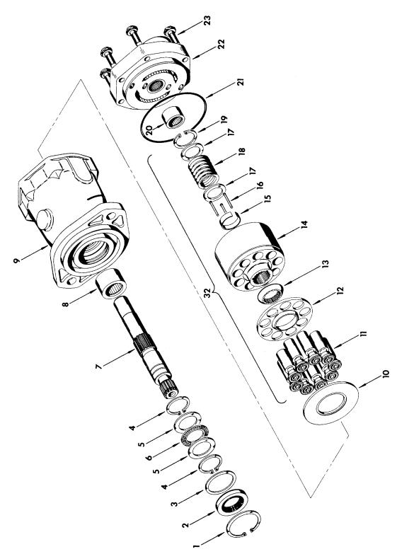
SECTION 1 FRAME
FIGURE 1-4. DRIVE MOTOR ASSEMBLY
FIG & ITEM # |
PART NUMBER |
DESCRIPTION |
QTY. |
REV. |
|
|
|
|
|
|
3160158 |
DRIVE MOTOR ASSEMBLY |
Ref. |
— |
1 |
Kit |
Ring, Retaining |
1 |
|
2 |
Kit |
Seal, Shaft |
1 |
|
3 |
7004906 |
Washer |
1 |
|
4 |
Kit |
Ring, Retaining |
2 |
|
5 |
7004907 |
Race, Thrust |
2 |
|
6 |
7004908 |
Bearing |
1 |
|
7 |
7007874 |
Shaft, Drive |
1 |
|
8 |
7004910 |
Bearing |
1 |
|
9 |
7007875 |
Housing Assembly (Includes Item 8) |
1 |
|
10 |
7007876 |
Camplate |
1 |
|
11 |
7007880 |
Rotating Kit Assembly |
1 |
|
12 |
7004917 |
Bearing |
1 |
|
13 |
Kit |
O-Ring |
1 |
|
14 |
7007878 |
Backplate Assembly (Includes Item 12) |
1 |
|
15 |
7007879 |
Bolt |
6 |
|
|
|
— — — — — — — — — — |
|
|
|
2900714 |
Repair Kit Includes Items 1,2,4 and 13) |
1 |
|
|
|
|
|
|
S E C T I O N
1
F
R A M E
3120673 |
1-19 |

|
SECTION 1 FRAME |
S |
FIGURE 1-5. DRIVE BRAKE ASSEMBLY - AUSCO (PRIOR TO MARCH 1992) |
E |
|
C |
|
T |
|
I |
|
O |
|
N |
|
1 |
|
F |
|
R |
|
A |
|
M |
|
E |
|
|
|
1-20 |
3120673 |

SECTION 1 FRAME
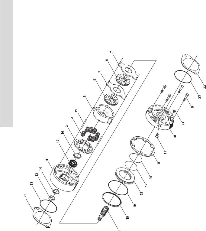
FIGURE 1-5. DRIVE BRAKE ASSEMBLY - AUSCO (PRIOR TO MARCH 1992)
FIG & ITEM # |
PART NUMBER |
DESCRIPTION |
QTY. |
REV. |
|
|
|
|
|
|
0920072 |
DRIVE BRAKE ASSEMBLY - AUSCO (PRIOR TO |
Ref. |
D |
|
|
MARCH 1992) |
|
|
1 |
7003047 |
Housing |
1 |
|
2 |
Kit |
Gasket |
1 |
|
3 |
7003049 |
Bearing |
1 |
|
4 |
Kit |
Seal, Oil |
1 |
|
5 |
7003051 |
Retainer, Spring |
1 |
|
6 |
7003052 |
Spring, Compression |
8 |
|
7 |
7003070 |
Shaft, Splined |
1 |
|
8 |
7000717 |
Pin, Torque |
2 |
|
9 |
7003054 |
Disc, Primary |
1 |
|
10 |
7003006 |
Spring, Separator |
6 |
|
11 |
7003055 |
Disc, Rotating |
3 |
|
12 |
7003056 |
Disc, Stationary |
3 |
|
13 |
7003057 |
Piston |
1 |
|
14 |
Kit |
Ring, Backup |
1 |
|
15 |
Kit |
O-Ring |
1 |
|
16 |
Kit |
Ring, Backup |
1 |
|
17 |
Kit |
O-Ring |
1 |
|
18 |
7000760 |
Bearing |
1 |
|
19 |
7000796 |
Screw, Bleeder |
1 |
|
20 |
7003071 |
Plate, Power |
1 |
|
21 |
7003007 |
Screw |
4 |
|
22 |
7003059 |
Valve, Pressure |
1 |
|
23 |
7000728 |
Plug |
1 |
|
24 |
Kit |
Gasket |
2 |
|
|
|
— — — — — — — — — — |
|
|
|
2900662 |
Seal Kit (Includes Items 2,4,14,15,16,17 and 24) |
1 |
|
|
|
|
|
|
S E C T I O N
1
F
R A M E
3120673 |
1-21 |
|
SECTION 1 FRAME |
S |
FIGURE 1-6. DRIVE BRAKE ASSEMBLY - MICO (MARCH 1992 TO PRESENT) |
E |
|
C |
|
T |
|
I |
|
O |
|
N |
|
1
F
R
A
M
E
1-22 |
3120673 |
Loading...