


Service and Maintenance Manual
Model
40H
40H+6
3120240
October 11, 2001
ANSI


INTRODUCTION - MAINTENANCE SAFETY PRECAUTIONS
SECTION A. INTRODUCTION - MAINTENANCE SAFETY
PRECAUTIONS
A.A GENERAL
This section contains the general safety precautions which must be observed during maintenance of the aerial platform. It is of utmost importance that maintenance personnel pay strict attention to these warnings and precautions to avoid possible injury to themselves or others, or damage to the equipment. A maintenance program must be followed to ensure that the machine is safe to operate.
MODIFICATION OF THE MACHINE WITHOUT CERTIFICATION BY A RESPONSIBLE AUTHORITY THAT THE MACHINE IS AT LEAST AS SAFE AS ORIGINALLY MANUFACTURED, IS A SAFETY VIOLATION.
The specific precautions to be observed during maintenance are inserted at the appropriate point in the manual. These precautions are, for the most part, those that apply when servicing hydraulic and larger machine component parts.
Your safety, and that of others, is the first consideration when engaging in the maintenance of equipment. Always be conscious of weight. Never attempt to move heavy parts without the aid of a mechanical device. Do not allow heavy objects to rest in an unstable position. When raising a portion of the equipment, ensure that adequate support is provided.
SINCE THE MACHINE MANUFACTURER HAS NO DIRECT CONTROL OVER THE FIELD INSPECTION AND MAINTENANCE, SAFETY IN THIS AREA RESPONSIBILITY OF THE OWNER/OPERATOR.
A.B HYDRAULIC SYSTEM SAFETY
It should be noted that the machines hydraulic systems operate at extremely high potentially dangerous pressures. Every effort should be made to relieve any system pressure prior to disconnecting or removing any portion of the system.
Relieve system pressure by cycling the applicable control several times with the engine stopped and ignition on, to direct any line pressure back into the reservoir. Pressure
feed lines to system components can then be disconnected with minimal fluid loss.
A.C MAINTENANCE
FAILURE TO COMPLY WITH SAFETY PRECAUTIONS LISTED IN THIS SECTION MAY RESULT IN MACHINE DAMAGE, PERSONNEL INJURY OR DEATH AND IS A SAFETY VIOLATION.
•NO SMOKING IS MANDATORY. NEVER REFUEL DURING ELECTRICAL STORMS. ENSURE THAT FUEL CAP IS CLOSED AND SECURE AT ALL OTHER TIMES.
•REMOVE ALL RINGS, WATCHES AND JEWELRY WHEN PERFORMING ANY MAINTENANCE.
•DO NOT WEAR LONG HAIR UNRESTRAINED, OR LOOSE-FITTING CLOTHING AND NECKTIES WHICH ARE APT TO BECOME CAUGHT ON OR ENTANGLED IN EQUIPMENT.
•OBSERVE AND OBEY ALL WARNINGS AND CAUTIONS ON MACHINE AND IN SERVICEMANUAL.
•KEEP OIL, GREASE, WATER, ETC. WIPED FROM STANDING SURFACES AND HAND HOLDS.
•USE CAUTION WHEN CHECKING A HOT, PRESSURIZED COOLANT SYSTEM.
•NEVER WORK UNDER AN ELEVATED BOOM UNTIL BOOM HAS BEEN SAFELY RESTRAINED FROM ANY MOVEMENT BY BLOCKING OR OVERHEAD SLING, OR BOOM SAFETY PROP HAS BEEN ENGAGED.
•BEFORE MAKING ADJUSTMENTS, LUBRICATING OR PERFORMING ANY OTHER MAINTENANCE, SHUT OFF ALL POWER CONTROLS.
•BATTERY SHOULD ALWAYS BE DISCONNECTEDDURING REPLACEMENT OF ELECTRICAL COMPONENTS.
•KEEP ALL SUPPORT EQUIPMENT AND ATTACHMENTS STOWED IN THEIR PROPER PLACE.
•USE ONLY APPROVED, NONFLAMMABLE CLEANING SOLVENTS.
3120240 |
– JLG Lift – |
a |

EFFECTIVITY CHANGES
|
REVISON LOG |
Aug, 1985 |
-Original Issue |
Nov. 1985 |
-Revised |
Oct. 1998 |
-Revised |
Aug. 1999 |
-Revised |
October 11, 2001 |
-Revised |
b |
– JLG Lift – |
3120240 |

TABLE OF CONTENTS
SUBJECT - SECTION, PARAGRAPH |
PAGE NO. |
|
SECTION |
A - INTRODUCTION - MAINTENANCE SAFETY PRECAUTIONS |
|
A.A |
General . . . . . . . . . . . . . . . . . . . . . . . . . . . . . . . . . . . . . . . . . . . . . . . . . . . . . . . . . . . . . . . . . . |
. . . .a |
A.B |
Hydraulic System Safety . . . . . . . . . . . . . . . . . . . . . . . . . . . . . . . . . . . . . . . . . . . . . . . . . . . . . |
. . . .a |
A.C |
Maintenance . . . . . . . . . . . . . . . . . . . . . . . . . . . . . . . . . . . . . . . . . . . . . . . . . . . . . . . . . . . . . . . |
. . .a |
EFFECTIVITY CHANGES . . . . . . . . . . . . . . . . . . . . . . . . . . . . . . . . . . . . . . . . . . . . . . . . . . . . . . . . . . . . . .b TABLE OF CONTENTS . . . . . . . . . . . . . . . . . . . . . . . . . . . . . . . . . . . . . . . . . . . . . . . . . . . . . . . . . . . . . . .I LIST OF ILLUSTRATIONS . . . . . . . . . . . . . . . . . . . . . . . . . . . . . . . . . . . . . . . . . . . . . . . . . . . . . . . . . . . . .II LIST OF TABLES . . . . . . . . . . . . . . . . . . . . . . . . . . . . . . . . . . . . . . . . . . . . . . . . . . . . . . . . . . . . . . . . . . . .III
SECTION |
1 - SPECIFICATIONS |
|
1.1 |
Capacities. . . . . . . . . . . . . . . . . . . . . . . . . . . . . . . . . . . . . . . . . . . . . . . . . . . . . . . . . . . . . . . . . . . . . |
1-1 |
1.2 |
Component Data. . . . . . . . . . . . . . . . . . . . . . . . . . . . . . . . . . . . . . . . . . . . . . . . . . . . . . . . . . . . . . . |
1-1 |
1.3Performance Data.. . . . . . . . . . . . . . . . . . . . . . . . . . . . . . . . . . . . . . . . . . . . . . . . . . . . . . . . . . . . . .1-3
1.4Torque Requirements.. . . . . . . . . . . . . . . . . . . . . . . . . . . . . . . . . . . . . . . . . . . . . . . . . . . . . . . . . . .1-3
1.5 Lubrication. . . . . . . . . . . . . . . . . . . . . . . . . . . . . . . . . . . . . . . . . . . . . . . . . . . . . . . . . . . . . . . . . . . .1-3
1.6 Pressure Settings. . . . . . . . . . . . . . . . . . . . . . . . . . . . . . . . . . . . . . . . . . . . . . . . . . . . . . . . . . . . . . .1-8
1.7 Cylinder Specifications . . . . . . . . . . . . . . . . . . . . . . . . . . . . . . . . . . . . . . . . . . . . . . . . . . . . . . . . . .1-9
1.8 Boom Tape . . . . . . . . . . . . . . . . . . . . . . . . . . . . . . . . . . . . . . . . . . . . . . . . . . . . . . . . . . . . . . . . . . .1-9
1.9 Major Components Weights . . . . . . . . . . . . . . . . . . . . . . . . . . . . . . . . . . . . . . . . . . . . . . . . . . . . .1-10
1.10 Critical Stability Weights . . . . . . . . . . . . . . . . . . . . . . . . . . . . . . . . . . . . . . . . . . . . . . . . . . . . . . . . .1-10
1.11 Serial Number Location (See Figure 1-4.) . . . . . . . . . . . . . . . . . . . . . . . . . . . . . . . . . . . . . . . . . . .1-10
SECTION 2 - PROCEDURES
2.1 |
General. . . . . . . . . . . . . . . . . . . . . . . . . . . . . . . . . . . . . . . . . . . . . . . . . . . . . . . . . . . . . . . . . . . . . . . |
2-1 |
2.2 |
Servicing And Maintenance Guidelines. . . . . . . . . . . . . . . . . . . . . . . . . . . . . . . . . . . . . . . . . . . . . . |
2-1 |
2.3 |
Lubrication Information. . . . . . . . . . . . . . . . . . . . . . . . . . . . . . . . . . . . . . . . . . . . . . . . . . . . . . . . . . |
2-2 |
2.4 |
Cylinders - Theory Of Operation. . . . . . . . . . . . . . . . . . . . . . . . . . . . . . . . . . . . . . . . . . . . . . . . . . . |
2-3 |
2.5 |
Valves - Theory Of Operation. . . . . . . . . . . . . . . . . . . . . . . . . . . . . . . . . . . . . . . . . . . . . . . . . . . . . . |
2-3 |
2.6 |
Boom Chains. (See Figure 2-1) . . . . . . . . . . . . . . . . . . . . . . . . . . . . . . . . . . . . . . . . . . . . . . . . . . . |
2-4 |
2.7 |
Wear Pads. . . . . . . . . . . . . . . . . . . . . . . . . . . . . . . . . . . . . . . . . . . . . . . . . . . . . . . . . . . . . . . . . . . . |
2-6 |
2.8 |
Cylinder Checking Procedure. . . . . . . . . . . . . . . . . . . . . . . . . . . . . . . . . . . . . . . . . . . . . . . . . . . . . |
2-7 |
2.9Cylinder Repair.. . . . . . . . . . . . . . . . . . . . . . . . . . . . . . . . . . . . . . . . . . . . . . . . . . . . . . . . . . . . . . . .2-9
2.10 Cylinder Removal And Installation. . . . . . . . . . . . . . . . . . . . . . . . . . . . . . . . . . . . . . . . . . . . . . . . . .2-12
2.11 Boom Maintenance. . . . . . . . . . . . . . . . . . . . . . . . . . . . . . . . . . . . . . . . . . . . . . . . . . . . . . . . . . . . .2-14
2.12Tilt Alarm Switch.. . . . . . . . . . . . . . . . . . . . . . . . . . . . . . . . . . . . . . . . . . . . . . . . . . . . . . . . . . . . . . .2-19
2.13 Horizontal High Speed Cutout Switch Adjustment Procedure. . . . . . . . . . . . . . . . . . . . . . . . . . . .2-19 2.14 Governor Checks And Addco Adjustment, Ford. . . . . . . . . . . . . . . . . . . . . . . . . . . . . . . . . . . . . . .2-20 2.15 Throttle Checks And Precision Governor Adjustments, Addco (See Figure 2-6.) . . . . . . . . . . . . .2-21 2.16 Electric Governor And Adjustments - Ford Engines. . . . . . . . . . . . . . . . . . . . . . . . . . . . . . . . . . . .2-22 2.17 Throttle Checks And Adjustments - Deutz F2l511 Engine. (See Figure 2-8.) . . . . . . . . . . . . . . . .2-29 2.18 Throttle Checks And Adjustments Wisconsin Engine. (See Figure 2-9.) . . . . . . . . . . . . . . . . . . . .2-33 2.19 Throttle Checks And Adjustments - Deutz F3l912 Engine. (See Figure 2-10.) . . . . . . . . . . . . . . .2-35 2.20 Throttle Checks And Adjustments - Deutz Engine F3l1011. (See Figure 2-11.) . . . . . . . . . . . . . .2-35 2.21 Pressure Setting Procedures. . . . . . . . . . . . . . . . . . . . . . . . . . . . . . . . . . . . . . . . . . . . . . . . . . . . . .2-38 2.22 Racine Proportional Air Gap Adjustment. . . . . . . . . . . . . . . . . . . . . . . . . . . . . . . . . . . . . . . . . . . . .2-58 2.23 Swing Bearing. . . . . . . . . . . . . . . . . . . . . . . . . . . . . . . . . . . . . . . . . . . . . . . . . . . . . . . . . . . . . . . . .2-59 2.24 Torque Hub, 2w/d. (See Figure 2-36.) . . . . . . . . . . . . . . . . . . . . . . . . . . . . . . . . . . . . . . . . . . . . . .2-63 2.25 Torque Hub 4wd. (See Figure 2-37.) . . . . . . . . . . . . . . . . . . . . . . . . . . . . . . . . . . . . . . . . . . . . . . .2-66 2.26 Swing Drive Brake, Mico (Machines Built Prior To May 1992). (See Figure 2-39.) . . . . . . . . . . . .2-71 2.27 Drive Brake, Mico. (Machines Built Prior To May 1992)(See Figure 2-40.) . . . . . . . . . . . . . . . . . .2-72 2.28 Swing Drive Brake, Ausco (Machines Built Prior To May 1992). (See Figure 2-41.) . . . . . . . . . . .2-75 2.29 Drive Brake, Ausco. (Machines Built Prior To May 1992) (See Figure 2-43.). . . . . . . . . . . . . . . . .2-77 2.30 Drive Brake, Mico. (Machines Built From May 1992 To S/n 33476) (See Figure 2-44.) . . . . . . . .2-79 2.31 Swing Brake, Mico. (Machines Built From May 1992 To S/n 33476) (See Figure 2-45.). . . . . . . .2-81
3120240 |
– JLG Lift – |
i |

TABLE OF CONTENTS (Continued)
2.32 Drive Brake, Mico. (Machines Built From S/n 33476 To Present) (See Figure 2-46.) . . . . . . . . . . 2-83 2.33 Swing Brake, Mico.(Machines Built From S/n 33476 To Present) (See Figure 2-46.) . . . . . . . . . . 2-85 2.34 Controllers . . . . . . . . . . . . . . . . . . . . . . . . . . . . . . . . . . . . . . . . . . . . . . . . . . . . . . . . . . . . . . . . . . . .2-87 2.35 Oscillating Axle Bleeding Procedure. . . . . . . . . . . . . . . . . . . . . . . . . . . . . . . . . . . . . . . . . . . . . . . . 2-87 2.36 Oscillating Axle Lockout Test. . . . . . . . . . . . . . . . . . . . . . . . . . . . . . . . . . . . . . . . . . . . . . . . . . . . . . 2-88 2.37 Basket Rotator Brake. (See Figure 2-48.) . . . . . . . . . . . . . . . . . . . . . . . . . . . . . . . . . . . . . . . . . . . .2-89 2.38 Free Wheeling Option. . . . . . . . . . . . . . . . . . . . . . . . . . . . . . . . . . . . . . . . . . . . . . . . . . . . . . . . . . . 2-89
2.39Spark Arrestor Mufflers.. . . . . . . . . . . . . . . . . . . . . . . . . . . . . . . . . . . . . . . . . . . . . . . . . . . . . . . . . . 2-89
2.40Footswitch Adjustment.. . . . . . . . . . . . . . . . . . . . . . . . . . . . . . . . . . . . . . . . . . . . . . . . . . . . . . . . . . 2-89
2.41 Hydraulic Pump W/hayes Pump Drive Coupling Lubrication. . . . . . . . . . . . . . . . . . . . . . . . . . . . . 2-89 2.42 Dual Fuel System. . . . . . . . . . . . . . . . . . . . . . . . . . . . . . . . . . . . . . . . . . . . . . . . . . . . . . . . . . . . . . . 2-89 2.43 Preventive Maintenance And Inspection Schedule. . . . . . . . . . . . . . . . . . . . . . . . . . . . . . . . . . . . . 2-90 2.44 Capacity Indicator . . . . . . . . . . . . . . . . . . . . . . . . . . . . . . . . . . . . . . . . . . . . . . . . . . . . . . . . . . . . . . 2-92
SECTION 3 - TROUBLESHOOTING
3.1 |
General. . . . . . . . . . . . . . . . . . . . . . . . . . . . . . . . . . . . . . . . . . . . . . . . . . . . . . . . . . . . . . . . . . . . . . . |
3-1 |
3.2 |
Troubleshooting Information. . . . . . . . . . . . . . . . . . . . . . . . . . . . . . . . . . . . . . . . . . . . . . . . . . . . . . |
3-1 |
3.3 |
Hydraulic Circuit Checks. . . . . . . . . . . . . . . . . . . . . . . . . . . . . . . . . . . . . . . . . . . . . . . . . . . . . . . . . |
3-1 |
LIST OF FIGURES
FIGURE NO. |
TITLE |
PAGE NO. |
1-1. Torque Chart. . . . . . . . . . . . . . . . . . . . . . . . . . . . . . . . . . . . . . . . . . . . . . . . . . . . . . . . . . . . . . . . . . 1-5 1-2. Lubrication Chart. (Sheet 1 of 2) . . . . . . . . . . . . . . . . . . . . . . . . . . . . . . . . . . . . . . . . . . . . . . . . . . . 1-6 1-2. Lubrication Chart. (Sheet 2 of 2) . . . . . . . . . . . . . . . . . . . . . . . . . . . . . . . . . . . . . . . . . . . . . . . . . . . 1-7 1-3. Serial Number Locations. . . . . . . . . . . . . . . . . . . . . . . . . . . . . . . . . . . . . . . . . . . . . . . . . . . . . . . . . 1-11 2-1. Typical Three Section Boom Assembly.. . . . . . . . . . . . . . . . . . . . . . . . . . . . . . . . . . . . . . . . . . . . . 2-5 2-2. Boom Positioning and Support, Cylinder Repair.. . . . . . . . . . . . . . . . . . . . . . . . . . . . . . . . . . . . . . 2-8 2-3. Poly-Pak Seal Installation.. . . . . . . . . . . . . . . . . . . . . . . . . . . . . . . . . . . . . . . . . . . . . . . . . . . . . . . . 2-11 2-4. Governor Adjustment, Ford with Addco. . . . . . . . . . . . . . . . . . . . . . . . . . . . . . . . . . . . . . . . . . . . . 2-20 2-5. Addco Adjustment, Ford. . . . . . . . . . . . . . . . . . . . . . . . . . . . . . . . . . . . . . . . . . . . . . . . . . . . . . . . . 2-21 2-6. Precision Governor Adjustment, Ford. (Sheet 1 of 2). . . . . . . . . . . . . . . . . . . . . . . . . . . . . . . . . . . 2-30 2-7. Precision governor Adjustment, Ford. (Sheet 2 of 2) . . . . . . . . . . . . . . . . . . . . . . . . . . . . . . . . . . . 2-31 2-8. Addco Actuator Adjustments, F2L511. . . . . . . . . . . . . . . . . . . . . . . . . . . . . . . . . . . . . . . . . . . . . . .2-32 2-9. Addco Actuator Adjustments, VG4D. . . . . . . . . . . . . . . . . . . . . . . . . . . . . . . . . . . . . . . . . . . . . . . . 2-34 2-10. Addco Actuator Adjustments, F3L912. . . . . . . . . . . . . . . . . . . . . . . . . . . . . . . . . . . . . . . . . . . . . . .2-36 2-11. Addco Actuator Adjustments, F3L1011. . . . . . . . . . . . . . . . . . . . . . . . . . . . . . . . . . . . . . . . . . . . . . 2-37 2-12. Racine Proportional Valve Pressure Setting.(Machines Built Prior To Mid 1987) (Sheet 1 of 2) . .2-39 2-13. Racine Proportional Valve Setting.(Machines Built Prior To Mid 1967) (Sheet 2 of 2) . . . . . . . . .2-40 2-14. Vickers Proportional Valve Pressure Setting, Machines Built To Present (Sheet 1 of 4) . . . . . . . . 2-41 2-15. Vickers Proportional Valve Pressure Setting, Machines Built To Present. (Sheet2 of 4) . . . . . . . . 2-42 2-16. Vickers Proportional Valve Pressure Setting, Machines Built To Present. (Sheet 3 Of 4) . . . . . . . 2-43 2-17. Vickers Proportional Valve Pressure Setting, Machines Built To Present. (Sheet 4 of 4) . . . . . . . 2-44 2-18. Vickers Proportional Valve Pressure Setting,
Machines Built Prior To 1989 With Accessory Valve. (Sheet 1 of 4). . . . . . . . . . . . . . . . . . . . . . . .2-45 2-19. Vickers Proportional Valve Pressure Setting,
Machines Built Prior To 1989 With Accessory Valve. (Sheet 2 of 4) . . . . . . . . . . . . . . . . . . . . . . . 2-46 2-20. Vickers Proportional Valve Pressure Setting,
Machines Built Prior To 1989 With Accessory Valve. (Sheet 3 Of 4) . . . . . . . . . . . . . . . . . . . . . . . 2-47 2-21. Vickers Proportional Valve Pressure Setting,
Machines Built Prior To 1989 With Accessary Valve. (Sheet 4 Of 4) . . . . . . . . . . . . . . . . . . . . . . . 2-48 2-22. Solenoid Valve Pressure Settings. (Machines Built Prior To 1992 With Steering Wheel) . . . . . . . 2-49 2-23. Pressure And Flow Settings (Machines Built Prior To May 1992 With Steering Wheel).. . . . . . . . 2-50 2-24. Vickers All Hydraulic Machines Pressure Settings (Sheet 1 of 4). . . . . . . . . . . . . . . . . . . . . . . . . .2-51
ii |
– JLG Lift – |
3120240 |

TABLE OF CONTENTS
2-25. Vickers All Hydraulic Machines Pressure Settings (Sheet 2 of 4). . . . . . . . . . . . . . . . . . . . . . . . . .2-52 2-26. Vickers All Hydraulic Machines Pressure Settings (Sheet 3 of 4). . . . . . . . . . . . . . . . . . . . . . . . . .2-53 2-27. Vickers All Hydraulic Machines Pressure Settings (Sheet 4 of 4). . . . . . . . . . . . . . . . . . . . . . . . . .2-54 2-28. Solenoid Valve Pressure Settings, Machines Built Before 1995. (Sheet 1 of 2) . . . . . . . . . . . . . .2-55 2-29. Solenoid Valve Pressure Settings, Machines Built from 1995 To Present. (Sheet 2 of 2) . . . . . . .2-56 2-30. Extend-A-Reach Valve Pressure and Speed Settings Model 40+6. . . . . . . . . . . . . . . . . . . . . . . .2-57 2-31. Racine Proportional Air Gap Adjustment, Machines Built Prior To Mid 1987. . . . . . . . . . . . . . . . .2-58 2-32. Swing Bearing Tolerance Boom Placement. . . . . . . . . . . . . . . . . . . . . . . . . . . . . . . . . . . . . . . . . .2-59 2-33. Swing Bolt Feeler Gauge Check. . . . . . . . . . . . . . . . . . . . . . . . . . . . . . . . . . . . . . . . . . . . . . . . . . .2-59 2-34. Swing Bearing Tolerance Measuring Point. . . . . . . . . . . . . . . . . . . . . . . . . . . . . . . . . . . . . . . . . . .2-61 2-35. Swing Bearing Torquing Sequence. . . . . . . . . . . . . . . . . . . . . . . . . . . . . . . . . . . . . . . . . . . . . . . . .2-63 2-36. Torque Hub Assembly, 2/WD.. . . . . . . . . . . . . . . . . . . . . . . . . . . . . . . . . . . . . . . . . . . . . . . . . . . . .2-64 2-37. Torque Hub 4/WD. . . . . . . . . . . . . . . . . . . . . . . . . . . . . . . . . . . . . . . . . . . . . . . . . . . . . . . . . . . . . .2-68 2-38. Torque Hub Carrier Timing. . . . . . . . . . . . . . . . . . . . . . . . . . . . . . . . . . . . . . . . . . . . . . . . . . . . . . .2-70 2-39. Swing Brake Assembly - Mico (Machines Built Prior To May 1992). . . . . . . . . . . . . . . . . . . . . . . .2-71 2-40. Drive Brake Assembly - Mico (Machines Built Prior To May 1992). . . . . . . . . . . . . . . . . . . . . . . . .2-73 2-41. Swing Brake Assembly - Ausco (Machines Built Prior to May 1992). . . . . . . . . . . . . . . . . . . . . . .2-76 2-42. Drive Brake, (machines Built Prior to May 1992). . . . . . . . . . . . . . . . . . . . . . . . . . . . . . . . . . . . . . .2-78 2-43. Drive Brake, Mico. (Machines Built From May 1992 To Machine S/N 33476) . . . . . . . . . . . . . . . .2-80 2-44. Swing Brake, Mico. (Machines Built From May 1992 To Machine S/N 33476) . . . . . . . . . . . . . . .2-82 2-45. Drive Brake, Mico. (Machines Built From S/N 33476 To Present) . . . . . . . . . . . . . . . . . . . . . . . . .2-84 2-46. Swing Brake, Mico. (Machines Built From S/N 33476 to Present) . . . . . . . . . . . . . . . . . . . . . . . . .2-86 2-47. Basket Rotator Brake. . . . . . . . . . . . . . . . . . . . . . . . . . . . . . . . . . . . . . . . . . . . . . . . . . . . . . . . . . . .2-88 2-48. Boom Tape Replacement Chart . . . . . . . . . . . . . . . . . . . . . . . . . . . . . . . . . . . . . . . . . . . . . . . . . . .2-92 2-49. Capacity Indicator Dial . . . . . . . . . . . . . . . . . . . . . . . . . . . . . . . . . . . . . . . . . . . . . . . . . . . . . . . . . .2-92 3-1. Wiring Diagram - Dual Fuel (Ford Or Wisconsin) . . . . . . . . . . . . . . . . . . . . . . . . . . . . . . . . . . . . . .3-20 3-2. Wiring Diagram - 110v Generator (Ford). . . . . . . . . . . . . . . . . . . . . . . . . . . . . . . . . . . . . . . . . . . . .3-21 3-3. Wiring Diagram - 110v Generator (Deutz). . . . . . . . . . . . . . . . . . . . . . . . . . . . . . . . . . . . . . . . . . . .3-22 3-4. Wiring Diagram - Platform Console (W/all Hydraulic Controls).. . . . . . . . . . . . . . . . . . . . . . . . . . .3-23 3-5. Wiring Diagram - Platform Console Standard (Sheet 1 Of 2). . . . . . . . . . . . . . . . . . . . . . . . . . . . .3-24 3-6. Wiring Diagram - Platform Console Standard (Sheet 2 Of 2). . . . . . . . . . . . . . . . . . . . . . . . . . . . .3-25 3-7. Wiring Diagram - Standard (Deutz F2l511/f3l912 & Wisconsin
Engine W/ Standard Controls) (Sheet 1 Of 2). . . . . . . . . . . . . . . . . . . . . . . . . . . . . . . . . . . . . . . . .3-26 3-8. Wiring Diagram - Standard (Deutz F2l4511/f3l912 & Wisconsin
Engine W/ Standard Controls) (Sheet 2 Of 2). . . . . . . . . . . . . . . . . . . . . . . . . . . . . . . . . . . . . . . . .3-27 3-9. Wiring Diagram - Standard (Deutz F2l511/f3l912 &
Engine W/ Hydraulic Controls) (Sheet 1 Of 2). . . . . . . . . . . . . . . . . . . . . . . . . . . . . . . . . . . . . . . . .3-28 3-10. Wiring Diagram - Standard (Deutz F2l511/f3l912 & Wisconsin
Engine W/ Hydraulic Controls) (Sheet 2 Of 2). . . . . . . . . . . . . . . . . . . . . . . . . . . . . . . . . . . . . . . . .3-29 3-11. Wiring Diagram - Standard (Deutz F3l1011 Engine W/ Standard Controls) (Sheet 1 Of 2). . . . . .3-30 3-12. Wiring Diagram - Standard (Deutz F3l1011 Engine W/ Standard Controls) (Sheet 2 Of 2). . . . . .3-31 3-13. Wiring Diagram - Standard (Deutz F3l1011 Engine W/ Hydraulic Controls) (Sheet 1 Of 2). . . . . .3-32 3-14. Wiring Diagram - Standard (Deutz F3l1011 Engine W/ Hydraulic Controls) (Sheet 2 Of 2). . . . . .3-33 3-15. Wiring Diagram - Standard (Ford Lrg425 Dis Engine W/ Standard Controls) (Sheet 1 Of 2).. . . .3-34 3-16. Wiring Diagram - Standard (Ford Lrg425 Dis Engine W/ Standard Controls) (Sheet 2 Of 2).. . . .3-35 3-17. Wiring Diagram - Standard (Ford Dis Engine W/ Hydraulic Controls) (Sheet 1 Of 2).. . . . . . . . . .3-36 3-18. Wiring Diagram - Standard (Ford Dis Engine W/ Hydraulic Controls) (Sheet 2 Of 2).. . . . . . . . . .3-37
LIST OF TABLES
TABLE NO. |
TITLE |
PAGE NO. |
2-1 Chain Stretch Tolerance.. . . . . . . . . . . . . . . . . . . . . . . . . . . . . . . . . . . . . . . . . . . . . . . . . . . . . . . . .2-7
2-2 Cylinder Piston Nut Torque Specification . . . . . . . . . . . . . . . . . . . . . . . . . . . . . . . . . . . . . . . . . . . .2-12
2-3 Holding Valve Torque Specifications. . . . . . . . . . . . . . . . . . . . . . . . . . . . . . . . . . . . . . . . . . . . . . . .2-12
2-4 Preventive Maintenance and Inspection Schedule. . . . . . . . . . . . . . . . . . . . . . . . . . . . . . . . . . . . .2-91
3-1 Platform Assembly Troubleshooting. . . . . . . . . . . . . . . . . . . . . . . . . . . . . . . . . . . . . . . . . . . . . . . .3-2
3120240 |
– JLG Lift – |
iii |

TABLE OF CONTENTS (Continued)
3-2 Boom Assembly Troubleshooting. . . . . . . . . . . . . . . . . . . . . . . . . . . . . . . . . . . . . . . . . . . . . . . . . . 3-3
3-3 Turntable Assembly Troubleshooting. . . . . . . . . . . . . . . . . . . . . . . . . . . . . . . . . . . . . . . . . . . . . . . 3-7
3-4 Chassis Assembly Troubleshooting. . . . . . . . . . . . . . . . . . . . . . . . . . . . . . . . . . . . . . . . . . . . . . . . 3-9
3-5 Hydraulic Assembly Troubleshooting. . . . . . . . . . . . . . . . . . . . . . . . . . . . . . . . . . . . . . . . . . . . . . . 3-14
3-6 Electrical Assembly Troubleshooting. . . . . . . . . . . . . . . . . . . . . . . . . . . . . . . . . . . . . . . . . . . . . . . 3-16
(INTENTIONAL BLANK PAGE)
iv |
– JLG Lift – |
3120240 |

SECTION 1 - SPECIFICATIONS
SECTION 1. SPECIFICATIONS
1.1CAPACITIES.
Fuel Tank - 37 Gallons (140.2 L)
Hydraulic Oil Tank - 37 U.S. Gallons
(104.2 L).
Hydraulic System (Including Tank) - 70 U.S.
Gallons (264.95 L).
Torque Hub Drive - 2.5 Pints (1.18 L).
Torque Hub Swing - 2.0 Pints (1.18 L).
NOTE: Torque Hubs should be one - half full of lubricant. (EPGL-90)
Engine Crankcase (Ford LSG423) w/Filter 5 quarts (4.73 L).
Engine Crankcase (Ford LRG423) w/Filter 5 quarts (4.73 L).
Engine Crankcase (Deutz F3L912) w/Filter 9.5 quarts (8.99 L).
Engine Crankcase (Deutz F3L1011) w/Filter 6.34 quarts (6 0 L).
Engine Crankcase (Deutz F2L511) w/Filter 3.5 quarts
Engine Crankcase (Wisconsin VG4D) w/Filter 5.0 quarts (4.73 L).
NOTE: Tolerance on all engine rpm settings is plus or minus 10%.
1.2COMPONENT DATA.
Engine - Ford LSG423/Lrg423.
Oil capacity - 5 quarts (4.73 L) w/Filter, 4 quarts (3.79 L) w/o Filter.
Cooling System - 16 quarts (15.14 L).
Low RPM - 1000, no load.
Mid RPM - 1800, no load.
High RPM - 3000, no load.
Alternator - 40 Amp, belt drive.
Battery - 1000 cold cranking Amps, 210 minutes reserve capacity,12 VDC.
Fuel Consumption Low RPM - 2.03 GPH
(7.68 LPH).
Fuel Consumption High RPM - 2.73 GPH
(10.33 LPH).
Horsepower - 63 @ 2800 RPM, no load.
Engine -Ford LRG-425 D.I.S.
Oil Capacity.
4.50 Quarts (4.25 1) w/Filter.
3.50 Quarts (3.31 1) w/o Filter.
Idle RPM - 1000.
Low RPM - 1800.
High RPM - 2800.
Alternator - 95 Amp, Belt Drive.
Battery - 1000 Cold Cranking Amps, 210 minute reserve Capacity, 12 VDC.
Fuel Consumption.
Low RPM - 3.45 GPH (13.06 lph).
High RPM - 4.60 GPH (17.41 lph).
Horsepower - 74 @ 3000 RPM, full load.
Cooling System - 16 Quarts (15.14 l.).
Engine - Deutz F3L912.
Oil capacity - 9.5 quarts (8.99L) w/Filter, 8.5 quarts (8.04 L) w/o Filter.
Low RPM 1800.
High RPM 2400.
Alternator - 85 Amp, belt drive.
Battery - 1000 cold cranking Amps, 210 minutes reserve capacity, 12VDC.
Fuel Consumption Low RPM - 2.03 GPH
(7.68 LPH).
Fuel Consumption High RPM - 2.73 GPH
(10.33 LPH).
Horsepower - 47 @ 2800 RPM, no load.
Engine - Deutz F3L1011.
Oil Capacity - 6.34 quarts (6.0 L) w/Filter, 5.8 quarts (5.5 L) w/0 Filter.
Low RPM 2000.
High RPM 3000.
Alternator - 60 Amp, belt drive.
3120240 |
– JLG Lift – |
1-1 |

SECTION 1 - SPECIFICATIONS
Battery - 1000 cold cranking Amps, 210 minutes reserve capacity, 12VDC.
Fuel Consumption Low RPM - 1.9 GPH (7.19
LPH).
Fuel Consumption High RPM - 2.5 GPH (9.46
LPH).
Horsepower - 42@ 3000 RPM, no load.
Engine - Deutz F2L511.
Oil Capacity - 3.5 quarts (3.31 L) w/Filter, 3.0 quarts (2.84 L) w/o Filter.
Low RPM 1800.
High RPM 2500.
Alternator - 33 Amp, belt drive.
Battery - 1000 cold cranking Amps, 210 minutes reserve capacity, 12 VDC.
Fuel Consumption Low RPM - 2.03 GPH (7.68 LPH). Fuel Consumption High RPM - 2.73 GPH (10.34 LPH). Horsepower - 47 @ 2300 RPM, full load.
Engine - Wisconsin VG4D.
Oil Capacity - 5 quarts (4.73 L) w/Filter, 4.5 quarts (4.26 L) w/o Filter.
Low RPM 1800, no load.
High RPM 2400, no load.
Alternator - 35 Amp, belt drive.
Battery - 1000 cold cranking Amps, 210 minutes reserve capacity, 12 VDC.
Fuel Consumption Low RPM - 3.21 GPH (12.15 LPH). Fuel Consumption High RPM - 3.89 GPH (14.72 LPH). Horsepower - 37 @ 2500 RPM, full load.
Swing System.
Swing Motor - Displacement - 3.0 in3/Rev.
Swing Hub - Ratio - 69:1.
Swing Brake - Automatic spring applied, hydraulically released disc brakes.
Hydraulic Pump.
Ford LSG423, Deutz F3L912, Wisconsin VG4D with Racine Valves (Single Speed Drive Motors).
First Section to Proportional Valve-Drive, Lift, Swing - 14.5 GPM (54.88 LPM).
Second Section to High Drive - 9.5 GPM (35.96 LPM).
Third Section to Bang-Bang valve level, Telescope, Steer, Rotate - 9.5 GPM (35.96 LPM).
Clockwise Rotation.
Ford LSG423, Deutz F3L912, Wisconsin VG4D with Racine Valves (2 Speed Drive Motors).
First Section to Proportional Valve-Drive, Lift, Swing - 10.8 GPM (40.88 LPM).
Second Section to High Drive - 6.3 GPM (23.85 LPM).
Third Section to Bang-Bang valve level, Telescope, Steer, Rotate - 6.3 GPM (23.85 LPM).
Clockwise Rotation.
Ford LSG423, Ford LRG423, Deutz F3L912, Deutz F3L1011, Wisconsin VG4D with Vickers Valves (2 Speed Drive Motors).
First Section to Proportional Valve-Drive, Lift, Swing - 15 GPM (56.78 LPM).
Second Section to High Drive - 9 GPM (34.07 LPM).
Third Section to Bang-Bang Valve Level, Telescope, Steer, Rotate - 9 GPM (34.07 LPM).
Clockwise Rotation.
Drive System.
Tires - 12.5 x 15, 12 ply rating, 72 PSI. (5 Bar) (4 WD Same).
Tires - 14 x 17.5, 8 ply rating, 45 PSI. (3 Bar) (4 WD Same).
Drive Motor Displacement - 2.48 in3/Rev.
Drive Hub Ratio - 49.29:1.
Steer System.
Tires - 12.5 x 15, 12 ply rating, 72 PSI. (5 Bar). Toe-in, adjust for 1/4 in. (6.35 mm) overall.
Auxiliary Power Pump.
Two section, 3.75 GPM (14.19 lpm) each section, 12 VDC motor, clockwise rotation.
Hydraulic Filter - Tank.
Return - Bypass Type.
10 Microns Nominal.
Hydraulic Filter - On-line (Racine Valve
Only).
Return - Non-Bypass Type.
1-2 |
– JLG Lift – |
3120240 |
SECTION 1 - SPECIFICATIONS
10 Microns Nominal.
1.3PERFORMANCE DATA.
Travel Speed.
2WD- 4.5 MPH (7.2 KM/HR). 4WD - 4.0 MPH (6.4 KM/HR).
Gradeability.
2WD25% or 14°slope, hard surface. 4WD - 40% or 22°slope, hard surface.
Turning Radius.
2WS/2WD16 ft. 6 in. (5.1 m). 2WS/4WD - 16 ft. 6 in. (5.1 m).
Boom Speed Lift.
Up 25 - 40 Seconds.
Down 20 - 30 Seconds.
Telescope Speed.
Extend 50 - 80 Seconds.
Retract 40 - 60 Seconds.
Swing Speed 360°.
Left 61 - 92 Seconds.
Right 61 - 92 Seconds.
Boom Elevation.
+74° (above horizontal). -22° (below horizontal). Model 40H+6.
74° +15° ART. (above horizontal) -22° -80° ART. (below horizontal)
Machine Weight.
Model 40H (2WD) - 11,600 LBS. (5,266 KG.). Model 40H (4WD) - 12,000 LBS. (5,448 KG.). Model 40H+6 - 13,350 LBS. (6,005 KG.).
Machine Stowed Height.
Model 40H (2WD) - 7 ft., 10 in. (2.39 M).
Model 40H (4WD) - 7 ft., 10 in. (2.39 M).
Machine Stowed Length.
Model 40H (2WD) - 25 ft.,2 in. (7.67 M).
Model 40H (4WD) - 25 ft.,2 in. (7.67 M).
Model 40H+6 (4WD) - 26 ft., 10 in. (8.18 M).
Machine Width.
Model 40H/40H+6(2WD/4WD) - 7 ft.,11 in. (2.41 M).
Wheelbase.
Model 40H/40H+6 (2WD/4WD) - 92 in. (2.34 M).
1.4TORQUE REQUIREMENTS.
Description |
To r q u e |
I n t e r - |
|
Value (Dry) |
v a l |
|
|
Hours |
A. Bearing To Chas- |
110 lbs. |
*200/500 |
sis |
(149 Nm) |
|
B. Bearing To Turn- |
220 lbs. |
*200/500 |
table |
(298 Nm) |
|
C. Wheel Lugs |
90 lbs. |
100 |
|
(122 Nm) |
|
D. Drive Hub |
150 lbs. |
*200/500 |
|
(204 Nm) |
|
E. Swing Hub |
110 lbs. |
*200/500 |
|
(149 Nm) |
|
NOTE: *Retorque after first 200 hours of operation and every 500 hours thereafter.
NOTE: See Procedure Section for tightening sequence of turntable bearing bolts.
NOTE: When maintenance becomes necessary or a fastener has loosened, refer to the Torque Chart to determine proper torque value.
1.5LUBRICATION.
Ford LSG423/LRG423/LRG425 Engine.
Single Viscosity Oils (SF, SF-SE, SF-CC, SF-CD).
When Outside Temp is |
Use SAE |
Consistently |
Viscosity Number |
3120240 |
– JLG Lift – |
1-3 |

SECTION 1 - SPECIFICATIONS
-10° F - +60° F. |
*10W |
(-24°C. to +16°C.) |
|
+10° F - + 90° F. |
20W-20 |
(+12°C. to +32°C.) |
|
Above +32° F. (+0°C.) |
30 |
Above + 50° F. (+10°C.) |
40 |
Multi-Viscosity Oils (SF, SF-SE, SF-CC, SF-CD). |
|
When Outside Temp |
Use SAE |
is Consistently |
Viscosity Number |
Below +10° F. (+12°C.) |
*5W-20 |
Below +60° F. (+16°C.) |
5W-30 |
-10° F - +90° F. |
10W-30 |
(-23°C. to+32°C>) |
|
Above -10° F. (23°C.) |
10W-40 or 10W-50 |
Above +20° F. (-23°C.) |
20W-40 or 20W-50 |
* Not recommended for severe service - including high RPM operation.
Deutz F3L912/F3L1011 Engine.
Single Viscosity Oils (CD-SE, CD-SF).
When Outside Temp |
Use SAE |
is Consistently |
Viscosity Number |
-20° F - +25° F. |
*10W |
(-29°C. to +4°C.) |
|
+5° F - + 50° F. |
20W-20 |
(+15°C. to +10°C.) |
|
+40° F - +85° F. |
30 |
(+4°C. to +30°C.) |
|
Above 75° F. (24°C.) |
40 |
Multi-Viscosity Oils (CD-SE, CD-SF). |
|
When Outside Temp |
Use SAE |
is Consistently |
Viscosity Number |
-40° F - +75° F. |
*5W-20 (Synthetic) |
(-40°C, to +24°C.) |
|
-15° F - +70° F. |
10W-30 |
(-26°C. to +21°C.) |
|
-15° F - +85° F. |
10W-40 |
(-26°C. to +30°C.) |
|
+5° F - +75° F. |
15W-30 |
(-21°C. to +24°C.) |
|
Above +5° F. (-21°C.) |
15W-40 |
* This viscosity can be used at colder temperatures only with engine oil preheating.
Wisconsin VG4D Engine.
Single Viscosity Oils (MS or SD).
When Outside Temp |
Use SAE |
is Consistently |
Viscosity Number |
+15° F - 0° F. |
10W |
+40° F - + 15° F. |
20-20W |
+120° F - + 40° F. |
30 |
Multi-Viscosity Oils (MS, SD, SE). |
|
When Outside Temp |
Use SAE |
is Consistently |
Viscosity Number |
Below Zero.( |
5W-20 |
NOTE: Crankcase oil should meet one of the following API classification grades: SE/CC, SE/CD, SF/CC, SF/ CD.
Table 1-1. Hydraulic Oil.
Hydraulic System |
SAE Viscosity |
Operating |
Grade |
Temperature Range |
|
0° F to +180° F (-18°C. to 83°C.) |
10W |
0° F to +210° F (-18° C to 99° C) |
10W-20/10W-30 |
50° F to 210° F (10° C to 99° C) |
20W-20 |
NOTE: Hydraulic oils must have anti-wear qualities at least to API Service Classification GL-3, and sufficient chemical stability for mobile hydraulic system service. JLG Industries recommends Mobilfluid 424 hydraulic oil, which has an SAE viscosity of 10W-30 and viscosity index of 152.
When temperatures remain consistently below +20° F. (-7° C.), an amount of no. 2 diesel fuel, not to exceed 20% of system capacity, may be added to the hydraulic oil reservoir. This diesel fuel will “thin” the hydraulic oil for easier cold weather operation, and will almost completely dissipate from the hydraulic system over a several month period of time. When cold weather is past, it may be necessary to drain and refill the hydraulic system to rid the system of any remaining diesel fuel.
Aside from JLG recommendations, it is not advisable to mix oils of different brands or types, as they may not contain the same required additives or be of comparable viscosities. If use of hydraulic oil other than Kendall Hyken 052 is desired or Mobilfluid 424, contact JLG Industries for proper recommendations.
1-4 |
– JLG Lift – |
3120240 |

SECTION 1 - SPECIFICATIONS
Figure 1-1. Torque Chart.
3120240 |
– JLG Lift – |
1-5 |

SECTION 1 - SPECIFICATIONS
Figure 1-2. Lubrication Chart. (Sheet 1 of 2)
1-6 |
– JLG Lift – |
3120240 |

SECTION 1 - SPECIFICATIONS
|
|
|
|
|
|
|
|
|
INDEX |
COMPONENT |
NUMBER/TYPE |
LUBE & METHOD |
INTERVAL |
|
|
|
NO. |
|
LUBE POINTS |
|
(HOURS) |
|
|
|
|
|
|
|
|
|
|
|
1. |
Wheel Drive Hub |
Fill Plug/1/2 Full |
EPGL (SAE - 90) |
*50/2 years |
|
|
|
2. |
Slave Leveling Cylinder - Barrel End |
1 |
Grease Fitting |
MPG - Pressure Gun |
150 |
|
|
3. |
Slave Leveling Cylinder - Rod End |
1 |
Grease Fitting |
MPG - Pressure Gun |
150 |
|
|
4. |
Rotary Platform Control Stand (If Equipped) |
2 |
Grease Fittings |
MPG - Pressure Gun |
150 |
|
|
|
Platform Pivot |
1 |
Grease Fitting |
MPG - Pressure Gun |
150 |
|
|
5. |
Rotary Worm Gear (If Equipped) |
1 |
Grease Fitting |
MPG - Pressure Gun |
150 |
|
|
6. |
Platform Hinges |
2 |
Grease Fittings |
MPG - Pressure Gun |
150 |
|
|
7. |
Platform Latch & Control Handle Slide Locks |
N/A |
SAE 10 - Oil Can |
A/R |
|
|
|
8. |
Telescope Cylinder Sheave (If Equipped) |
1 |
Grease Fitting |
MPG - Pressure Gun |
150 |
|
|
9. |
Swing Bearing (Remote Access) |
2 |
Grease Fittings |
MPG - Pressure Gun |
150 |
|
|
10. |
Lift Cylinder - Barrel End (Remote Access) |
1 |
Grease Fitting |
MPG - Pressure Gun |
150 |
|
|
11. |
Lift Cylinder - Rod End |
2 |
Grease Fittings |
MPG - Pressure Gun |
150 |
|
|
12. |
Master Level Cylinder - Rod End |
1 |
Grease Fitting |
MPG - Pressure Gun |
150 |
|
|
13. |
Master Level Cylinder - Barrel End |
1 |
Grease Fitting |
MPG - Pressure Gun |
150 |
|
|
14. |
Boom Pivot Bushings |
2 |
Grease Fittings |
MPG - Pressure Gun |
150 |
|
|
15. |
Engine Crankcase |
Fill Cap/Drain Plug |
EO (Refer to end. manual) |
**10/150 |
|
|
|
16. |
Lockout Cylinder - Barrel End |
1 |
Grease Fittings |
MPG - Pressure Gun |
100 |
|
|
|
(If Equipped) |
|
|
|
|
|
|
17. |
Lockout Cylinder - Rod End (If Equipped) |
2 |
Grease Fittings |
MPG - Pressure Gun |
150 |
|
|
18. |
Oscillating Axle Pivot Pin (If Equipped) |
1 |
Grease Fitting |
MPG - Pressure Gun |
*****150 |
|
|
19. |
Steer Cylinder |
2 |
Grease Fittings |
MPG - Pressure Gun |
150 |
|
|
20. |
Steer Spindle |
2 |
Grease Fittings |
MPG - Pressure Gun |
150 |
|
|
21. |
Steer Spindle - 4WD (If Equipped) |
4 |
Grease Fittings |
MPG - Pressure Gun |
150 |
|
|
22. |
Tie Rod Ends |
2 |
Grease Fittings |
MPG - Pressure Gun |
150 |
|
|
23. |
Tie Rods - Two Hitch (If Equipped) |
4 |
Grease Fittings |
MPG - Pressure Gun |
150 |
|
|
24. |
Towing Hitch (If Equipped) |
1 |
Grease Fitting |
MPG - Pressure Gun |
150 |
|
|
25. |
Wheel Bearings |
N/A |
MPG - Repack |
500 |
|
|
|
26. |
Wheel Drive Hubs - 4WD (If Equipped) |
Fill Plug/1/2 Full |
EPGL (SAE - 90) |
*50/2 yrs. |
|
|
|
27. |
Swing Hub |
Fill Plug |
EPGL (SAE - 90) |
*50/2 yrs. |
|
|
|
28. |
Swing Bearing & Pinion Gear Teeth |
N/A |
MPG - Brush |
100 |
|
|
|
29. |
Door & Access Panel Hinges |
N/A |
SAE 10 - Oil Can |
A/R |
|
|
|
30. |
Hydraulic Filter Element, Return |
N/A |
Replacement Element |
***40/300 |
|
|
|
31. |
Hydraulic Filter Element, Inline |
N/A |
Replacement Element |
***40/300 |
|
|
|
32. |
Hydraulic Fluid (Oil) |
Fill Plug/1/2 Full |
HO |
****10/2 yrs. |
|
|
|
33. |
E.A.R. Pivot (If Equipped) |
2 |
Grease Fittings |
MPG - Pressure Gun |
150 |
|
|
34. |
E.A.R. Lift Cylinder Barrel End (If Equipped) |
1 |
Grease Fitting |
MPG - Pressure Gun |
150 |
|
|
35. |
E.A.R. Link Boom End (If Equipped) |
2 |
Grease Fittings |
MPG - Pressure Gun |
150 |
|
|
36. |
E.A.R. Lift Cylinder Rod End (If Equipped) |
1 |
Grease Fitting |
MPG - Pressure Gun |
150 |
|
|
37. |
E.A.R. Slave Cylinder Pivot Points |
2 |
Grease Fittings |
MPG - Pressure Gun |
150 |
|
|
|
(If Equipped) |
|
|
|
|
|
|
38. |
E.A.R. Slave Cylinder Rod End |
1 |
Grease Fitting |
MPG - Pressure Gun |
150 |
|
|
|
(If Equipped) |
|
|
|
|
|
|
39. |
E.A.R. Link Platform End (If Equipped) |
1 |
Grease Fitting |
MPG - Pressure Gun |
150 |
|
|
40. |
E.A.R. Platform Pivot (If Equipped) |
1 |
Grease Fitting |
MPG - Pressure Gun |
150 |
|
|
|
|
|
|
|
|
|
*Check oil level after every 50 hours of operation. Change oil after every 2 years (1200 hrs.) of operation. **Check oil level after every 10 hours of operation. Change oil after every 3 months (150 hrs.) of operation.
***Replace filter element after first 40 hours of operation, then after every 6 months (300 hrs.) of operation thereafter.
****Check oil level after every 10 hours of operation.Change oil after every 2 years(1200 hrs.) of operation.
*****It will be necessary to swing the boom over side of frame and remove the frame shield to gain access to the grease fitting.
NOTE: Lubrication intervals are based on machine operations under normal conditions. for machines used in multi shift operations and /or exposed to hostile environments or conditions, lubrication frequencies must be increased accordingly.
Figure 1-2. Lubrication Chart. (Sheet 2 of 2)
3120240 |
– JLG Lift – |
1-7 |

SECTION 1 - SPECIFICATIONS
Lubrication Specifications.
Table 1-2. Lubrication Specifications.
KEY SPECIFICATIONS
MPG |
Multipurpose Grease having a minimum |
|
dripping point of 350 degrees F. Excellent |
|
water resistance and adhesive qualities; |
|
and b eing of extreme pressure ty pe |
|
(Timken OK 40 pounds minimum). |
EPGL |
Extreme Pressure Gear Lube (oil) meeting |
|
API Service Classification GL-5 or Mil-Spec |
|
Mil-L-2105. |
HO |
Hydraulic Oil. API Service Classification |
|
GL-3, SAE 10W-20, Viscosity Index 152, |
|
e.g. Kendall Hyken 052 or Mobilfluid 424. |
EO |
Engine (crankcase) Oil. Gas - API SF/SG |
|
class, MIL-L-2104. Diesel - API CC/CD |
|
class, MIL-L-2104B/MIL-L-2104C. |
NOTE: Refer to Lubrication Chart, Figure 1-2, for specific lubrication procedures.
Solenoid Valve.
Main Relief - 2500 psi. (172.38 Bar). Telescope In.
a.2 Section Boom - 2000 psi
(137.9 Bar).
b.3 Section Boom - 2500 psi.
(172.38 Bar).
Telescope Out - 1500 psi (103.43 Bar). Rotate - 2500 psi (172.38 Bar).
Level Up - 2500 psi (172.38 Bar). Level Down - 1500 psi (103.43 Bar). Steer.
a.Without Wheel - 1500 psi.(103.43 Bar).
b.Without Wheel - 2500 psi.(172.38 Bar).
1.6PRESSURE SETTINGS.
NOTE: All pressure are given in pounds per square inch (psi), with the metric equivalent, Bar, in parentheses.
Racine Proportional Valve.
Racine.
Main Relief - 2800 psi. (193.06 Bar).
Drive - 2800 psi. (193.06 Bar).
Lift Up - 2800 psi. (193.06 Bar).
Lift Down - 1100 psi. (75.85 Bar).
Swing - 1000 psi. (68.95 Bar).
Vickers Proportional Valve.
Vickers.
Drive - 3000 psi.(206.85 Bar).
Lift Up - 2500 psi.(172.38 Bar). Lift Down - 1500 psi. (103.43 Bar).
Telescope In - 2500 psi. (172.38 Bar). Telescope Out - 1500 psi. (103.43 Bar). Swing - 1200 psi. (82.74 Bar).
Main Relief - 3200 psi (220.64 Bar).
Sequence Cartridge - 400 psi. (27.58 Bar).
Pressure Reducing - 600 psi. (41.37 Bar).
Vickers - Proportional Valve w/o Tele.
Vickers.
Drive - 3000 psi. (206.85 Bar).
Lift Up - 2500 psi. (172.38 Bar).
Lift Down - 1200 psi. (82.74 Bar).
Swing - 1100 psi. (75.85 Bar).
Accessory.
Main Relief - 3200 psi. (220.64 Bar). Sequence Cartridge - 450 psi. (31.03 Bar). Pressure Reducing - 600 psi. (41.37 Bar).
1-8 |
– JLG Lift – |
3120240 |
SECTION 1 - SPECIFICATIONS
3 Stack Racine Bang-Bang Valve.
Main Relief - 2500 psi. (172.38 Bar).
Steer - 2000 psi. (137.9 Bar).
4WD Steer Pressure - 2000 psi. (137.9 Bar). Extend-A-Reach Racine Valve.
Extend Up - 2500 psi. (172.38 Bar).
Extend Down - 800 psi. (55.16 Bar).
NOTE: Refer to Section 2 for pressure setting procedures.
1.7CYLINDER SPECIFICATIONS
Table 1-3. CYLINDER SPECIFICATIONS.
DESCRIPTION |
BORE |
STROKE |
R O D |
|
|
|
DIA. |
|
|
|
|
Master Level |
2.50 |
15.25 |
1.25 |
Slave Level |
2.50 |
15.21 |
1.25 |
Lift |
6.00 |
23.50 |
2.50 |
L o c k o u t |
3.00 |
4.56 |
1.25 |
(Oscillating Axle) |
|
|
|
L o c k - |
3.00 |
4.06 |
1.25 |
o u t |
|
|
|
(4WD) |
|
|
|
Telescope |
3.00 |
174.18 |
2.00 |
(2 Section Boom) |
|
|
|
Telescope |
3.00 |
110.31 |
2.00 |
(3 Section Boom) |
|
|
|
Steer (2WD) |
3.00 |
8.06 |
1.25 |
Steer (4WD) |
3.00 |
9.81 |
1.50 |
|
|
|
|
|
Extend-A-Reach |
|
|
|
|
|
|
Lift |
3.00 |
12.687 |
2.00 |
Slave |
3.50 |
7.25 |
1.75 |
1.8BOOM TAPE
Two Section Boom (American Standard).
Red - 64 in. (162.56 cm).
Yellow - 41 in. (104.14 cm).
Blue - 71.50 in. (181.61 cm).
Three Section Boom (American Standard).
Red - 24.06 in. (61.11 cm).
Yellow - 20.50 in. (52.07 cm).
Blue - 70.75 in. (179.70 cm).
Two Section Boom (Canadian Standard).
Red - 70.75 in. (179.71 cm).
Yellow - 46.24 in. (117.47 cm).
Blue - 59.49 in. (151.12 cm).
3120240 |
– JLG Lift – |
1-9 |

SECTION 1 - SPECIFICATIONS
1.9 MAJOR COMPONENTS WEIGHTS
|
|
|
|
|
|
|
|
|
TABLE 1-4. COMPONENT WEIGHTS. |
|
|
|
|
||
|
|
|
MODEL40H |
MODEL 40H+6 |
|
||
|
|
|
LBS. |
KG |
LBS. |
KG |
|
|
Platform - 36" x 48" (91.4 cm x 122 cm) |
170 |
78 |
170 |
78 |
|
|
|
w/Control Box. |
|
|
|
|
|
|
|
Platform - 36" x 60" (91.4 cm x 152 cm) |
185 |
84 |
185 |
84 |
|
|
|
w/Control Box. |
|
|
|
|
|
|
|
Platform - 36" x 72" (91.4 cm x 182.88 cm) |
200 |
90 |
200 |
90 |
|
|
|
w/Control Box. |
|
|
|
|
|
|
|
Platform - 36" x 96" (91.4 cm x 243.84 cm) |
240 |
109 |
- - - |
- - - |
|
|
|
w/Control Box. |
|
|
|
|
|
|
|
2 Section Boom (Includes Boom Lift |
1795 |
814 |
2165 |
982 |
|
|
|
Cylinder, Rotator and Support). |
|
|
|
|
|
|
|
3 Section Boom (Includes Boom Lift |
2275 |
1032 |
2645 |
1200 |
|
|
|
Cylinder, Rotator and Support). |
|
|
|
|
|
|
|
Turntable Complete. |
4687 |
2126 |
5925 |
2688 |
|
|
|
Frame Complete (Includes Pneumatic Tires and Wheels). |
5020 |
2277 |
5020 |
2277 |
|
|
|
(2WD) |
|
|
|
|
|
|
|
Frame Complete (Includes Pneumatic Tires and Wheels). |
5420 |
2458 |
5420 |
2458 |
|
|
|
(4WD) |
|
|
|
|
|
|
|
Complete Machine - 2WD. |
11,600 |
5,266 |
13,350 |
6,055 |
|
|
|
Complete Machine - 4WD. |
12,000 |
5,448 |
13,750 |
6,237 |
|
|
|
|
|
|
|
|
|
|
1.10 CRITICAL STABILITY WEIGHTS
|
|
|
|
|
|
|
|
|
|
|
|
|
TABLE 1-5.CRITICAL STABILITY WEIGHTS. |
|
|
||||
|
|
|
|
MODEL 40H |
|
MODEL 40H+6 |
|
|
|
|
|
|
|
LBS. |
KG |
LBS. |
|
KG |
|
|
Counterweight |
1.5:1 |
|
910 |
412.8 |
2490 |
|
1129.5 |
|
|
(If Removable) |
|
|
|
|
|
|
|
|
|
|
2:1 |
|
1075 |
487.6 |
2690 |
|
1220.2 |
|
|
Tires |
sIZE |
|
12.5L -15 |
|
12.5L -15 |
|
|
|
|
(ballasted Only) |
|
|
|
|
|
|
|
|
|
|
Weight |
|
305 |
138.4 |
305 |
|
138.4 |
|
|
Engine |
Ford |
|
525 |
238.1 |
525 |
|
238.1 |
|
|
|
Deutz |
|
600 |
272.2 |
600 |
|
272.2 |
|
|
|
Wisconsin |
|
- - - |
- - - |
- - - |
|
- - - |
|
|
|
|
|
|
|
|
|
|
|
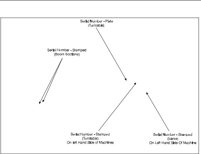
1.11 SERIAL NUMBER LOCATION (SEE FIGURE 1-4.)
A serial number plate is affixed to the left rear front of the turntable. If the serial number plate is damaged or missing, the machine serial number is stamped on the left side of the frame between front and rear wheels, below turntable bearing. In addition, the last five digits of the serial number are stamped on top of the fly and base end of the boom and on the left side of the turntable.
1-10 |
– JLG Lift – |
3120240 |
SECTION 1 - SPECIFICATIONS
Figure 1-3. Serial Number Locations.
3120240 |
– JLG Lift – |
1-11 |

SECTION 1 - SPECIFICATIONS
intentional blank page
1-12 |
– JLG Lift – |
3120240 |
SECTION 2 - PROCEDURES
SECTION 2. PROCEDURES
2.1GENERAL.
This section provides information necessary to perform maintenance on the aerial platform. Descriptions, techniques and specific procedures are designed to provide the safest and most efficient maintenance for use by personnel responsible for ensuring the correct installation and operation of machine components and systems.
WHEN AN ABNORMAL CONDITION IS NOTED AND PROCEDURES CONTAINED HEREIN DO NOT SPECIFICALLY RELATE TO THE NOTED IRREGULARITY, WORK SHOULD BE STOPPED AND TECHNICALLY QUALIFIED GUIDANCE OBTAINED BEFORE WORK IS RESUMED.
The maintenance procedures included consist of servicing and component removal and installation, disassembly and assembly, inspection, lubrication and cleaning. Information on any special tools or test equipment is also provided where applicable.
2.2SERVICING AND MAINTENANCE
GUIDELINES.
General.
The following information is provided to assist you in the use and application of servicing and maintenance procedures contained in this chapter.
Safety and Workmanship.
Your safety, and that of others, is the first consideration when engaging in the maintenance of equipment. Always be conscious of weight. Never attempt to move heavy parts without the aid of a mechanical device. Do not allow heavy objects to rest in an unstable position. When raising a portion of the equipment, ensure that adequate support is provided.
Cleanliness.
1.The most important single item in preserving the long service life of a machine is to keep dirt and foreign materials out of the vital components. Precautions have been taken to safeguard against this. Shields, covers, seals, and filters are provided to keep air, fuel, and oil supplies clean; however, these items must be maintained on a scheduled basis in order to function properly.
2.At any time when air, fuel, or oil lines are disconnected, clear adjacent areas as well as the openings and fittings themselves. As soon as a line or component is disconnected, cap or cover all openings to prevent entry of foreign matter.
3.Clean and inspect all parts during servicing or maintenance, and assure that all passages and openings are unobstructed. Cover all parts to keep them clean. Be sure all parts are clean before they are installed. New parts should remain in their containers until they are ready to be used.
Components Removal and Installation.
4.Use adjustable lifting devices, whenever possible, if mechanical assistance is required. All slings (chains, cables, etc.) should be parallel to each other and as near perpendicular as possible to top of part being lifted.
5.Should it be necessary to remove a component on an angle, keep in mind that the capacity of an eyebolt or similar bracket lessens, as the angle between the supporting structure and the component becomes less than 90 degrees.
6.If a part resists removal, check to see whether all nuts, bolts, cables, brackets, wiring, etc., have been removed and that no adjacent parts are interfering.
Component Disassembly and Reassembly.
When disassembling or reassembling a component, complete the procedural steps in sequence. Do not partially disassemble or assemble one part, then start on another. Always recheck your work to assure that nothing has been overlooked. Do not make any adjustments, other than those recommended, without obtaining proper approval.
Pressure-Fit Parts.
When assembling pressure-fit parts, use an “anti-seize” or molybdenum disulfide base compound to lubricate the mating surface.
Bearings.
1.When a bearing is removed, cover it to keep out dirt and abrasives. Clean bearings in nonflammable cleaning solvent and allow to drip dry. Compressed air can be used but do not spin the bearing.
2.Discard bearings if the races and balls (or rollers) are pitted, scored, or burned.
3.If bearing is found to be serviceable, apply a light coat of oil and wrap it in clean (waxed) paper. Do not
3120240 |
– JLG Lift – |
2-1 |

SECTION 2 - PROCEDURES
unwrap reusable or new bearings until they are |
Battery. |
ready to install. |
|
|
4.Lubricate new or used serviceable bearings before installation. When pressing a bearing into a retainer or bore, apply pressure to the outer race. If the bearing is to be installed on a shaft, apply pressure to the inner race.
Gaskets.
Check that holes in gaskets align with openings in the mating parts. If it becomes necessary to hand-fabricate a gasket, use gasket material or stock of equivalent material and thickness. Be sure to cut holes in the right location, as blank gaskets can cause serious system damage.
Bolt Usage and Torque Application.
1.Use bolts of proper length. A bolt which is too long will bottom before the head is tight against its related part. If a bolt is too short, there will not be enough thread area to engage and hold the part properly. When replacing bolts, use only those having the same specifications of the original, or one which is equivalent.
2.Unless specific torque requirements are given within the text, standard torque values should be used on heat-treated bolts, studs, and steel nuts, in accordance with recommended shop practices.
(See Figure 1-1.)
Hydraulic Lines and Electrical Wiring.
Clearly mark or tag hydraulic lines and electrical wiring, as well as their receptacles, when disconnecting or removing them from the unit. This will assure that they are correctly reinstalled.
Hydraulic System.
1.Keep the system clean. If evidence of metal or rubber particles are found in the hydraulic system, drain and flush the entire system.
2.Disassemble and reassemble parts on clean work surface. Clean all metal parts with non-flammable cleaning solvent. Lubricate components, as required, to aid assembly.
Lubrication.
Service applicable components with the amount, type, and grade of lubricant recommended in this manual, at the specified intervals. When recommended lubricants are not available, consult your local supplier for an equivalent that meets or exceeds the specifications listed.
Clean battery, using a non-metallic brush and a solution of baking soda and water. Rinse with clean water. After cleaning, thoroughly dry battery and coat terminals with an anti corrosion compound.
Lubrication and Servicing.
Components and assemblies requiring lubrication and servicing are shown in Figures 1-2.
2.3 LUBRICATION INFORMATION.
Hydraulic System.
1.The primary enemy of a hydraulic system is contamination. Contaminants enter the system by various means, e.g., using inadequate hydraulic oil, allowing moisture, grease, filings, sealing components, sand, etc., to enter when performing maintenance, or by permitting the pump to cavitate due to insufficient system warm-up or leaks in the pump supply (suction) lines.
2.The design and manufacturing tolerances of the component working parts are very close, therefore, even the smallest amount of dirt or foreign matter entering a system can cause wear or damage to the components and generally results in faulty operation. Every precaution mst be taken to keep hydraulic oil clean, including reserve oil in storage. Hydraulic system filters should be checked, cleaned, and/or replaced as necessary, at the specified intervals required in Figure 1-2. Always examine filters for evidence of metal particles.
3.Cloudy oils indicate a high moisture content which permits organic growth, resulting in oxidation or corrosion. If this condition occurs, the system must be drained, flushed, and refilled with clean oil.
4.It is not advisable to mix oils of different brands or types, as they may not contain the same required additives or be of comparable viscosities. Good grade mineral oils, with viscosities suited to the ambient temperatures in which the machine is operating, are recommended for use.
NOTE: Metal particles may appear in the oil or filters of new machines due to the wear-in of meshing components.
2-2 |
– JLG Lift – |
3120240 |

SECTION 2 - PROCEDURES
Hydraulic Oil.
5.Refer to Table 1-1 for recommendations for viscosity ranges.
6.JLG recommends Mobilfluid 424 hydraulic oil, which has an SAE viscosity of 10W-30 and a viscosity index of 152.
NOTE: Start-up of hydraulic system with oil temperatures below -15° F. is not recommended. If it is necessary to start the system in a sub-zero environment, it will be necessary to heat the oil with a low density, 100VAC heater to a minimum temperature of -15° F.
7.The only exception to the above is to drain and fill the system with Mobil DTE 11 oil or its equivalent. This will allow start up at temperatures down to - 20°F. However, use of this oil will give poor performance at temperatures above 120° F. Systems using DTE 11 oil should not be operated at temperatures above 200°F. under any condition.
Changing Hydraulic Oil.
8.Use of any of the recommended crankcase or hydraulic oils eliminates the need for changing the oil on a regular basis. However, filter elements must be changed after the first 40 hours of operation and every 250 hours thereafter. If it is necessary to change the oil, use only those oils meeting or exceeding the specifications appearing in this manual. If unable to obtain the same type of oil supplied with the machine, consult local supplier for assistance in selecting the proper equivalent. Avoid mixing petroleum and synthetic base oils. JLG Industries recommends changing the hydraulic oil annually.
9.Use every precaution to keep the hydraulic oil clean. If the oil must be poured from the original container into another, be sure to clean all possible contaminants from the service container. Always clean the mesh element of the filter and replace the cartridge any time the system oil is changed.
10.While the unit is shut down, a good preventive maintenance measure is to make a thorough inspection of all hydraulic components, lines, fittings, etc., as well as a functional check of each system, before placing the machine back in service.
Lubrication Specifications.
Specified lubricants, as recommended by the component manufacturers, are always the best choice, however, multi-purpose greases usually have the qualities which meet a variety of single purpose grease requirements. Should any question arise, regarding the use of greases in maintenance stock, consult your local supplier for evalua-
tion. Refer to Table 1-2 for an explanation of the lubricant
key designations appearing in the Lubrication Chart.
2.4CYLINDERS - THEORY OF OPERATION.
Systems Incorporating Double Acting
Cylinders:
Cylinders are of the double-acting type. Systems incorporating double-acting cylinders are as follows: Lift, Telescope, Platform Leveling, Steer and Lockout. A double acting cylinder is one that requires oil flow to operate the cylinder rod in both directions. Directing oil (by actuating the corresponding control valve to the piston side of the cylinder) forces the piston to travel toward the rod end of the barrel, extending the cylinder rod (piston attached to rod). When the oil flow is stopped, movement of rod will stop. By directing oil to the rod side of the cylinder, the piston will be forced in the opposite direction and the cylinder rod will retract.
Holding valves are used in the Lift, Telescope, Slave Level and lockout circuits to prevent retraction of the cylinder rod, should a hydraulic line rupture or a leak develop between the cylinder and its related control valve.
2.5VALVES - THEORY OF OPERATION.
Solenoid Control Valves (Bang-Bang).
Control valves used are four-way three-position solenoid valves of the sliding spool design. When a circuit is activated and the control valve solenoid energizes, the spool is shifted and the corresponding work port opens to permit oil flow to the component in the selected circuit with the opposite work port opening to reservoir. Once the circuit is deactivated (control returned to neutral) the valve spool returns to neutral (center) and oil flow is then directed through the valve body and returns to reservoir. A typical control valve consist of the valve body, sliding spool, and two solenoid assemblies . The spool is machine fitted in the bore of the valve body. Lands on the spool divide the bore into various chambers, which when the spool is shifted, align with corresponding ports in the valve body open to common flow. At the same time other ports would be blocked to flow. The spool is spring loaded to center position, therefore when the control is released, the spool automatically returns to neutral, prohibiting any flow through the circuit.
3120240 |
– JLG Lift – |
2-3 |

SECTION 2 - PROCEDURES
Proportional Control Valve - Vickers.
CMX series valves provide a power output matching that required by the load. A small line connected to a loadsensing port feeds load pressure back to the pump. The pump senses the difference between the load and pump outlet pressures, and varies the pump displacement to keep the difference constant. This differential pressure is applied across the valves meter-in spool, with the effect that pump flow is determined by the degree of spool opening, independent of load pressure. Return lines are connected together simplifying routing of return flow and to help reduce cavitation. Load sensing lines connect through shuttle valves to feed the highest load signal back to the pump. Integral actuator port relief valves, anti cavitation check valves, and load check valves are standard. The load drop check prevents any drop of a suspended load before upward movement.
Relief Valves.
Main relief valves are installed at various points with the hydraulic system to protect associated systems and components against excessive pressure. Excessive pressure can be developed when a cylinder reaches its limit of travel and the flow of pressurized fluid continues from the system control. The relief valve provides an alternate path for the continuing flow from the pump, thus preventing rupture of the cylinder, hydraulic line or fitting. Complete failure of the system pump is also avoided by relieving circuit pressure. The relief valve is installed in the circuit between the pump outlet (pressure line) and the cylinder of the circuit, generally as an integral part of the system valve bank. Relief pressures are set slightly higher than the load requirement, with the valve diverting excess pump delivery back to the reservoir when operating pressure of the component is reached.
Relief Valves.
Crossover relief valves are used in circuits where the actuator requires an operating pressure lower than that supplied to the system. When the circuit is activated and the required pressure at the actuator is developed, the crossover relief diverts excess pump flow to the reservoir, individual, integral reliefs are provided for each side of the circuits.
2.Torque fly boom retract chains, adjust to 28 ft. lbs. (38 NM).
3.Torque fly boom extend chains, adjust to 28 ft. lbs. (38 NM).
4.Cycle boom (extend at least three feet and return to the fully retracted position).
5.Recheck fly boom retract chains (28 ft. lbs. (38 NM) required).
6.Recheck fly boom extend chains (28 ft. lbs. (38 NM) required).
7.Repeat steps #2, #3 and #4 if necessary.
8.Check for proper operation of boom.
JLG Industries, Inc. requires a complete boom disassembly, per instructions outlined in the 2-11 boom disassem- b ly, every tw o years. All boom chains and related components (i.e., sheaves, pins, sprockets, wear pads, etc.) must also be inspected and replaced (as necessary) during this disassembly.
A more frequent disassembly of the boom assembly and inspection of the boom chains and related components is required if machine is exposed to hostile environments or conditions (i.e. extreme cold, dust, sand, blasting grit, salt, chemicals, etc.), which could adversely affect boom operation. Such a disassembly is required if either debris has accumulated inside the boom assembly or an inspection of the boom chain and related components, in accordance with the INSPECTION PROCEDURES in this section, reveals any discrepancies to the boom chain or related components.
An immediate disassembly of the boom assembly and inspection of the boom chains and related components is required if any of the following conditions occur:
1.Erratic boom operation or unusual noise exists, due to discrepancies listed in the INSPECTION PROCEDURES in this section, to the boom chains or related components. See troubleshooting section in Service Manual for probable causes.
2.Chain adjustment is required more often than specified in Service Manual or links need to be removed (chain shortened) to make adjustment.
3.Machine is idle for an extended period (6 months or longer.)
2.6 BOOM CHAINS. (SEE FIGURE 2-1)
Adjusting Procedures.
ENSURE MACHINE IS ON A FIRM AND LEVEL SURFACE.
1. Fully retract boom in the horizontal position.
4. Boom is overloaded or sustained a shock load.
FAILURE TO DISASSEMBLE THE BOOM ASSEMBLY AND PROPERLY INSPECT AND/OR REPLACE THE BOOM CHAINS AND RELATED COMPONENTS (I.E., SHEAVES, PINS, SPROCKETS, WEAR PADS, ETC.) COULD RESULT IN THE DAMAGE AND/OR BREAKAGE OF THE BOOM CHAINS AND/OR RELATED COMPO-
2-4 |
– JLG Lift – |
3120240 |

SECTION 2 - PROCEDURES
NENTS. DAMAGE AND/OR BREAKAGE OF THESE ITEMS COULD RESULT IN UNCONTROLLED EXTENSION OR RETRACTION OF
THE BOOM ASSEMBLY AND COULD CAUSE SERIOUS INJURY OR DEATH TO PERSONNEL OPERATING THE JLG BOOM LIFT.
Figure 2-1. Typical Three Section Boom Assembly.
Inspection Procedures.
5. Inspect boom chains for the following condition:
Wear: Always inspect that segment of chain that operates over a sheave. As the chain flexes over the extend/retract sheaves, joints and plate edges very gradually wear. Chain “stretch” can be measured using a manufacturers wear scale or steel tape. When chains have elongated 3% they must be removed and replaced. Refer to Table 1 for proper chain specifications and allowable stretch tolerances. Peening and wear of chain plate edges are caused by sliding over a chain worn contact face of a sheave, or unusually heavy loads. All of the above require replacement of the chain and correction of the cause. Chain side wear, noticeable when pin heads and outside plates show a definite wear pattern, is caused by misalignment of the sheave/chain anchors and must be corrected promptly. Do not repair chains; if a section of chain is damaged, replace the entire chain set.
Lubrication: One of the most important but often overlooked factors is adequate lubrication. In addition to reducing internal friction, maintaining
a film of oil on all chain surfaces will inhibit rusting and corrosion. This is important as corrosion of highly stressed, hardened steel chain components can cause a major reduction in the load capacity of leaf chain and result in link plate cracking.
NOTE: The need for lubrication can be determined by the presence of rust on the exposed portions of chain.
Rust and Corrosion: Rust and corrosion will cause a major reduction in the load carrying capacity of the chain, because these are primary reasons for side plate cracking. The initial lubrication at the factory is applied in a hot dip tank to assure full penetration into the joint. Do not steam clean or degrease this lubricant on chains. A grade of SAE 30 or 40 weight, non detergent motor oil should be used as a supplemental lubricant and a film of this oil should be constantly maintained on the surfaces and internal joints. At time of chain installation, factory Lube must be supplemented by a maintenance program to provide a film of oil on the chains at all times. If chains are corroded, they must be inspected, especially the outside plates, for cracks in-line with the pins. If cracks are found, replace the chain; if no cracks are discovered, lubricate the chains by dipping in heated oil, and reinstall on the machine. Keep chains lubricated.
Fatigue Cracks: Fatigue is a phenomenon that affects most metals, and is the most common cause of chain plate failures. Fatigue cracks are found through the link holes, perpendicular (90 degrees) from the
3120240 |
– JLG Lift – |
2-5 |
SECTION 2 - PROCEDURES
pin in-line position. Inspect chains carefully after long time use and heavy loading for this type of crack. If any cracks are discovered, replace all chains, as seemingly sound plates are on the verge of cracking. Fatigue and ultimate strength failures on JLG Lifts are incurred as a result of severe abuse as design specs are well within the rated lifting capacity of these chains.
extend in an arc-like path, often parallel to the rolling grain of the material.
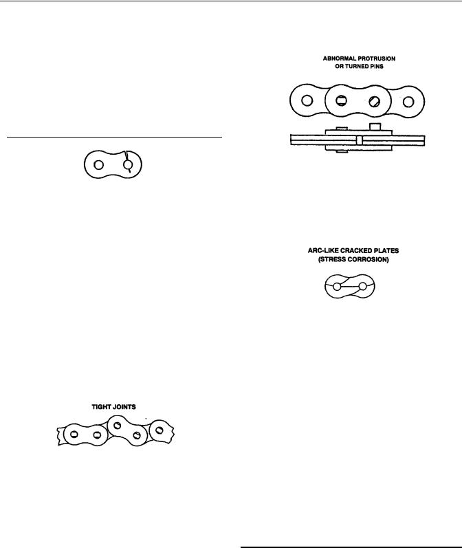
Tight Joints: All joints in the roller chain should flex freely. On roller chain, tight joints are usually caused by rust/corrosion, or the inside plates “walking” off the bushing. Limber up rusty/corroded chains (after inspecting care fully) with a heavy application of oil (preferably a hot oil dip). Tap inside “walking” plates inward; if “walking” persists, replace the chain. This type of problem is accelerated by poor lubrication maintenance practice, and most tight joint chains have been operated with little or no lubrication. Tight joints on leaf chain are generally caused by:
1.Bent pins or plates.
2.Rusty joints.
3.Peened plate edges.
Oil rusty chains, and replace chains with bent or peened chain components. Keep chains lubricated.
Protruding or Turned Pins: Chains operating with inadequate lube generate tremendous friction between the pin and plates (pin and bushing on roller chain). In extreme cases, this frictional torque can actually turn the pins in the outside press-fit plates. Inspect for turned pins, which can be easily spotted as the “V” flats on the pin heads are no longer in line. Replace all chains showing evidence of turned or protruding pins. Keep chains lubricated.
Stress Corrosion Cracking: The outside link plates, which are heavily press-fitted to the pins, are particularly susceptible to stress corrosion cracking. Like fatigue cracks, these initiate at the point of highest stress (aperture) but tend to
Also, more then one crack can often appear on a link plate. In addition to rusting, this condition can be caused by exposure to an acidic or caustic medium or atmosphere. Stress corrosion is an environmentally assisted failure. Two conditions must be present - corrosive agent and static stress. In the chain, static stress is present at the aperture due to the press fit pin.
No cycle motion is required and the plates can crack during idle periods. The reactions of many chemical agents (such as battery acid fumes) with hardened metals liberate hydrogen which attacks and weakens the metal grain structure.
Chain Anchors, Sheaves and Pins: An inspection of the chain must include a close examination of chain anchors, sheaves and pins. Check chain anchors for wear breakage and misalignment. Anchors with worn or broken fingers should be replaced. They should also be adjusted to eliminate twisting the chain for an even load distribution.
Sheaves should be inspected for worn flanges, which would indicate misalignment, and wear on the outside diameter of the sheave. A worn sheave can mean several problems, as follows:
1.Chains too tight.
2.Sheave bearings/pin bad.
3.Bent/misaligned chains.
2.7WEAR PADS.
1.Shim up wear pads within 1/16 in. (1.59 mm) tolerance between wear pad and adjacent surface.
2.Replace wear pads when worn within 1/8 in. (3.18
mm)of threaded insert.
2-6 |
– JLG Lift – |
3120240 |

|
|
SECTION 2 - PROCEDURES |
|
Table 2-1. Chain Stretch Tolerance. |
|
|
|
|
Chain |
Pin To Pin |
Allowable |
Size |
Measurement |
Stretch |
|
|
|
0.50 in. (1.27 cm) pitch |
14 in. (36 cm) or 28 pitches |
0.42 in. (1.07 cm) |
|
|
|
0.625 in. (1.59 cm) pitch |
15 in. (38 cm) or 24 pitches |
0.45 in. (1.14 cm) |
|
|
|
0.75 in. (1.91 cm) pitch |
15 in. (38 cm) or 20 pitches |
0.45 in. (1.14 cm) |
|
|
|
1 in. (2.54 cm) pitch |
14 in. (36 cm) or 14 pitches |
0.42 in. (1.07 cm) |
|
|
|
1.25 in. (3.18 cm) pitch |
15 in. (38 cm) or 12 pitches |
0.45 in. (1.14 cm) |
|
|
|
1.75 in. (4.45 cm) pitch |
14 in. (36 cm) or 8 pitches |
0.42 in. (1.07 cm) |
|
|
|
2 in. (5.08 cm) pitch |
14 in. (36 cm) or 7 pitches |
0.42 in. (1.07 cm) |
|
|
|
|
|
|
2.8CYLINDER CHECKING PROCEDURE.
NOTE: Cylinder checks must be performed any time a cylinder component is replaced or when improper system operation is suspected.
Cylinders Without Counterbalance Valves.
Steer Cylinder and Master Cylinder.
3.Using all applicable safety precautions, activate engine and fully extend cylinder to be checked. Shut down engine.
4.Carefully disconnect hydraulic hose from retract port of cylinder. There will be initial weeping of hydraulic fluid which can be caught in a suitable container. After the initial discharge there should be no further leakage from the retract port.
5.Activate engine and extend cylinder.
6.If cylinder retract port leakage is less than 6-8 drops per minute, carefully reconnect hose to port and retract cylinder. If leakage continues at a rate of 6-8 drops per minute or more, cylinder repairs must be made.
7.With cylinder fully retracted, shut down engine and carefully disconnect hydraulic hose from cylinder extend port.
8.Activate engine and retract cylinder. Check extend port for leakage.
9.If extend port leakage is less than 6-8 drops per minute, carefully reconnect hose to extend port, then activate cylinder through one complete cycle and check for leaks. If leakage continues at a rate of 6-8 drops per minute or more, cylinder repairs must be made.
Cylinders With Single Counterbalance
Valve.
Lift Cylinder, Telescope Cylinder and Extend- A-Reach Lift
Cylinder.
OPERATE ALL FUNCTIONS FROM GROUND CONTROLS.
1.Using all applicable safety precautions, activate hydraulic system.
WHEN WORKING ON THE LIFT CYLINDER, RAISE THE BOOM TO HORIZONTAL AND PLACE A BOOM PROP APPROXIMATELY 1 INCH (2.50 CM) BELOW THE BOOM. DO NOT WORK ON THE CYLINDER WITHOUT A SUITABLE PROP IN PLACE. REFER TO FIGURE 2-2.
2.After completing the above, shut down hydraulic system and allow machine to sit for 10-15 minutes. Turn IGNITION SWITCH to ON, move control switch or lever for applicable cylinder in each direction, then turn IGNITION SWITCH to OFF. This is done to relieve pressure in the hydraulic lines. Carefully remove hydraulic hoses from appropriate cylinder port block.
3.There will be initial weeping of hydraulic fluid, which can be caught in a suitable container. After the initial discharge, there should not be any further leakage from the ports. If leakage continues at a rate of 6-8 drops per minute or more, the following cylinder repairs must be made. If the retract port is leaking, the piston seals are defective and must be replaced. If the extend port is leaking, the counterbalance valve is defective and must be replaced.
4.If no repairs are necessary or when repairs have been made, carefully reconnect hydraulic hoses to the appropriate ports.
3120240 |
– JLG Lift – |
2-7 |
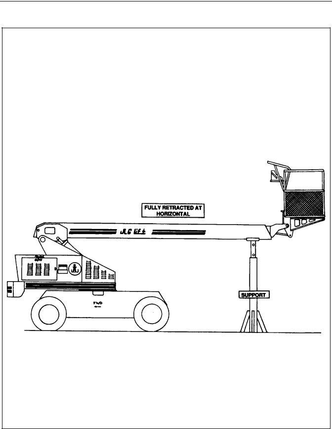
SECTION 2 - PROCEDURES
Figure 2-2. Boom Positioning and Support, Cylinder Repair.
2-8 |
– JLG Lift – |
3120240 |
SECTION 2 - PROCEDURES
5.If used, remove boom prop from beneath boom, activate hydraulic system and run cylinder through one complete cycle to check for leaks.
Cylinders With Dual Counterbalance Valves.
Platform Slave Level Cylinder, Lockout Cylinder
and Extend-A-Reach Level Cylinder.
OPERATE ALL FUNCTIONS FROM GROUND CONTROL STATION ONLY.
1.Using all applicable safety precautions, activate hydraulic system.
2.When working on the platform slave level cylinder, stroke platform slave level cylinder forward until platform sits at a 45° angle.
3.Shut down hydraulic system and allow machine to sit for 10-15 minutes. If machine is equipped with a bang-bang or proportional control valves, turn IGNITION SWITCH to ON, move control switch or lever for applicable cylinder in each direction, then turn IGNITION SWITCH to OFF. If machine is equipped with hydraulic control valves, move control lever for applicable cylinder in each direction. This is done to relieve pressure in the hydraulic lines. Carefully remove hydraulic hoses from appropriate cylinder port block.
4.There will be initial weeping of hydraulic fluid which can be caught in a suitable container. After the initial discharge, there should not be any further leakage from the ports. If leakage continues at a rate of 6-8 drops per minute or more, the counterbalance valve is defective and must be replaced.
5.To check piston seals, carefully remove the counterbalance valve from the retract port. After initial discharge there should not be any further leakage from the ports. If leakage occurs at a rate of 6-8 drops per minute or more, the piston seals are defective and must be replaced.
6.If no repairs are necessary or when repairs have been made, replace counterbalance valve and carefully connect hydraulic hoses to cylinder port block.
7.If used, remove lifting device from upright or remove prop from below boom, activate hydraulic system and run cylinder through one complete cycle to check for leaks.
2.9CYLINDER REPAIR.
NOTE: The following are general procedures that apply to all of the cylinders on this machine. Procedures that apply to a specific cylinder will be so noted.
Disassembly.
DISASSEMBLY OF THE CYLINDER SHOULD BE PERFORMED ON A CLEAN WORK SURFACE IN A DIRT FREE WORK AREA.
1.Connect a suitable auxiliary hydraulic power source to the cylinder port block fitting.
DO NOT FULLY EXTEND CYLINDER TO THE END OF STROKE. RETRACT CYLINDER SLIGHTLY TO AVOID TRAPPING PRESSURE.
2.Operate the hydraulic power source and extend the cylinder. Shut down and disconnect the power source. Adequately support the cylinder rod, if applicable.
CYLINDERS WITH DOUBLE HOLDING VALVES. BEFORE REMOVING HOLDING VALVES CRACK BLEEDERS TO RELEASE PRESSURE.
3.If applicable, remove the cartridge-type holding valve and fittings from the cylinder port block. Discard o-rings.
4.Place the cylinder barrel into a suitable holding fixture. Tap around outside of cylinder head retainer with a suitable hammer to shatter loctite.
5.Using a suitable spanner wrench, loosen the cylinder head retainer, if applicable, and/or cylinder head gland, and remove from cylinder barrel.
6.Attach a suitable pulling device to the cylinder rod port block end or cylinder rod end, as applicable.
EXTREME CARE SHOULD BE TAKEN WHEN REMOVING THE CYLINDER ROD, HEAD, AND PISTON. AVOID PULLING THE ROD OFFCENTER, WHICH COULD CAUSE DAMAGE TO THE PISTON AND CYLINDER BARREL SURFACES.
3120240 |
– JLG Lift – |
2-9 |

SECTION 2 - PROCEDURES
7.With the barrel clamped securely, apply pressure to the rod pulling device and carefully withdraw the complete rod assembly from the cylinder barrel.
8.Using suitable protection, clamp the cylinder rod in a vise or similar holding fixture as close to the piston as possible.
9.Remove the set screw (s), if applicable, and nut which attach the piston to the rod, and remove the piston. Discard self-locking set screws.
10.Remove the piston rings.
11.Remove and discard the piston o-rings, seal rings, and backup rings.
12.Remove the set screw, if applicable, piston spacer, and wear ring, if applicable, from the rod.
13.Remove the rod from the holding fixture. Remove the cylinder head gland and retainer, if applicable. Discard the o-rings, back-up rings, rod seals, and wiper seals.
Cleaning and Inspection.
1.Clean all parts thoroughly in an approved cleaning solvent.
2.Inspect the cylinder rod for scoring, tapering, ovality, or other damage. If necessary, dress rod with Scotch Brite or equivalent. Replace rod if necessary.
3.Inspect threaded portion of rod for excessive damage. Dress threads as necessary.
4.Inspect inner surface of cylinder barrel tube for scoring or other damage. Check inside diameter for tapering or ovality. Replace if necessary.
5.Inspect threaded portion of barrel for damage. Dress threads as necessary.
6.Inspect piston surface for damage and scoring and for distortion. Dress piston surface or replace piston as necessary.
7.Inspect seal and o-ring grooves in piston for burrs and sharp edges. Dress applicable surfaces as necessary.
8.Inspect cylinder head inside diameter for scoring or other damage and for ovality and tapering. Replace as necessary.
9.Inspect seal and o-ring grooves in head for burrs and sharp edges. Dress applicable surfaces as necessary.
11.Inspect cylinder head outside diameter for scoring or other damage and ovality and tapering. Replace as necessary.
12.If applicable, inspect thread ring for scoring or other damage. Dress threads or applicable surfaces as necessary.
13.If applicable, inspect seal grooves in thread ring for burrs and sharp edges. Dress applicable surfaces as necessary.
14.If applicable, inspect rod and barrel bushings for signs of correct lubrication and excessive wear. Replace as necessary.
15.Inspect travel limiting collar or spacer for burrs and sharp edges. If necessary, dress inside diameter surface with Scotch Brite or equivalent.
16.If applicable, inspect port block fittings and holding valve. Replace as necessary.
17.Inspect the oil ports for blockage or the presence of dirt or other foreign material. Repair as necessary.
18.If applicable, inspect piston rings for cracks or other damage. Replace as necessary.
NOTE: Steps (19) through (22) apply to the 3 Section Boom telescope cylinder only.
19.Inspect chain sheave bushings for scoring, tapering, ovality and for excessive wear and evidence of correct lubrication. Replace bushing as necessary.
20.Inspect sheave chain groove for damage. Replace sheave assembly as necessary.
21.Inspect sheave attach pin for scoring or other damage and for evidence of correct lubrication. Dress pin surface with Scotch Brite or equivalent or replace pin as necessary.
22.Inspect sheave pin lubrication drilling and fitting for blockage or the presence of dirt or other foreign material. Repair as necessary.
Assembly.
NOTE: Prior to cylinder assembly, ensure that the proper cylinder seal kit is used. See your JLG Parts Manual.
Apply a light film of hydraulic oil to all components prior to assembly.
WHEN INSTALLING ‘POLY-PAK’ PISTON SEALS, ENSURE SEALS ARE INSTALLED PROPERLY. REFER TO FIGURE 2-3 FOR COR-
10.If applicable, inspect cylinder head retainer or end RECT SEAL ORIENTATION. IMPROPER SEAL INSTALLATION cap for surface or thread damage. Repair or replace COULD RESULT IN CYLINDER LEAKAGE AND IMPROPER CYLIN-
as necessary. |
DER OPERATION. |
2-10 |
– JLG Lift – |
3120240 |
 Loading...