


Diamond
DA40/40F

Copyright © 2006 Garmin Ltd. or its subsidiaries.All rights reserved.
This manual reflects the operation of System Software version 369.11 or later for the Diamond DA40 or DA40F. Some differences in operation may be observed when comparing the information in this manual to earlier or later software versions.
Garmin International, Inc., 1200 East 151st Street, Olathe, Kansas 66062, U.S.A.
Tel: 913/397.8200 |
Fax: 913/397.8282 |
Garmin AT, Inc., 2345 Turner Road SE, Salem, OR 97302, U.S.A. |
|
Tel: 503/391.3411 |
Fax: 503/364.2138 |
Garmin (Europe) Ltd., Unit 5,The Quadrangle,Abbey Park Industrial Estate, Romsey, Hampshire S051 9DL, U.K |
|
Tel: 44/0870.8501241 |
Fax: 44/0870.8501251 |
Garmin Corporation, No. 68, Jangshu 2nd Road, Shijr,Taipei County,Taiwan |
|
Tel: 886/02.2642.9199 |
Fax: 886/02.2642.9099 |
Website Address: www.garmin.com
Except as expressly provided herein, no part of this manual may be reproduced, copied, transmitted, disseminated, downloaded or stored in any storage medium, for any purpose without the express written permission of Garmin. Garmin hereby grants permission to download a single copy of this manual and of any revision to this manual onto a hard drive or other electronic storage medium to be viewed for personal use,provided that such electronic or printed copy of this manual or revision must contain the complete text of this copyright notice and provided further that any unauthorized commercial distribution of this manual or any revision hereto is strictly prohibited.
Garmin® is a registered trademark of Garmin Ltd. or its subsidiaries, and G1000® is a trademark of Garmin Ltd. or its subsidiaries. These trademarks may not be used without the express permission of Garmin.
Bendix/King® and Honeywell® are registered trademarks of Honeywell International, Inc.; Becker® is a registered trademark of Becker Flugfunkwerk GmbH; NavData® is a registered trademark of Jeppesen, Inc.; and XM® is a registered trademark of XM Satellite Radio, Inc..
July 2006 |
Printed in the U.S.A. |
Garmin G1000 Pilot’s Guide for the Diamond DA40/40F |
190-00592-02 Rev.A |

LIMITED WARRANTY
LIMITED WARRANTY
This Garmin product is warranted to be free from defects in materials or workmanship for two years from the date of purchase. Within this period, Garmin will, at its sole option, repair or replace any components that fail in normal use. Such repairs or replacement will be made at no charge to the customer for parts and labor,provided that the customer shall be responsible for any transportation cost. This warranty does not cover failures due to abuse, misuse, accident, or unauthorized alterations or repairs.
THE WARRANTIES AND REMEDIES CONTAINED HEREIN ARE EXCLUSIVEAND IN LIEU OF ALL OTHER WARRANTIES EXPRESS OR IMPLIED OR STATUTORY, INCLUDING ANY LIABILITY ARISING UNDER ANY WARRANTY OF MERCHANTABILITY OR FITNESS FOR A PARTICULAR PURPOSE, STATUTORY OR OTHERWISE. THIS WARRANTY GIVES YOU SPECIFIC LEGAL RIGHTS, WHICH MAY VARY FROM STATE TO STATE.
IN NO EVENT SHALL GARMIN BE LIABLE FOR ANY INCIDENTAL, SPECIAL, INDIRECT OR CONSEQUENTIAL DAMAGES, WHETHER RESULTING FROM THE USE, MISUSE, OR INABILITY TO USE THIS PRODUCT OR FROM DEFECTS IN THE PRODUCT. Some states do not allow the exclusion of incidental or consequential damages, so the above limitations may not apply to you.
Garmin retains the exclusive right to repair or replace the unit or software, or to offer a full refund of the purchase price, at its sole discretion. SUCH REMEDY SHALL BE YOUR SOLE AND EXCLUSIVE REMEDY FOR ANY BREACH OF WARRANTY.
To obtain warranty service, contact your local GarminAuthorized Service Center. For assistance in locating a Service Center near you, visit the Garmin Website at “http://www.garmin.com” or contact Garmin Customer Service at 800-800-1020.
190-00592-02 Rev.A |
Garmin G1000 Pilot’s Guide for the Diamond DA40/40F |
i |

WARNINGS, CAUTIONS, AND NOTES
WARNING: Navigation and terrain separation must NOT be predicated upon the use of the terrain function. The G1000Terrain Proximity feature is NOT intended to be used as a primary reference for terrain avoidance and does not relieve the pilot from the responsibility of being aware of surroundings during flight. The Terrain Proximity feature is only to be used as an aid for terrain avoidance and is not certified for use in applications requiring a certified terrain awareness system. Terrain data is obtained from third party sources. Garmin is not able to independently verify the accuracy of the terrain data.
WARNING: The displayed minimum safe altitudes (MSAs) are only advisory in nature and should not be relied upon as the sole source of obstacle and terrain avoidance information. Always refer to current aeronautical charts for appropriate minimum clearance altitudes.
WARNING:TheGarminG1000,asinstalledinDiamondDA40/40Faircraft,hasaveryhighdegreeoffunctional integrity. However, the pilot must recognize that providing monitoring and/or self-test capability for all conceivable system failures is not practical. Although unlikely, it may be possible for erroneous operation to occur without a fault indication shown by the G1000. It is thus the responsibility of the pilot to detect such an occurrence by means of cross-checking with all redundant or correlated information available in the cockpit.
WARNING: The altitude calculated by G1000 GPS receivers is geometric height above Mean Sea Level and could vary significantly from the altitude displayed by pressure altimeters, such as the GDC 74A Air Data Computer, or other altimeters in aircraft. GPS altitude should never be used for vertical navigation. Always use pressure altitude displayed by the G1000 PFD or other pressure altimeters in aircraft.
WARNING: The Jeppesen database used in the G1000 system must be updated regularly in order to ensure that its information remains current. Updates are released every 28 days. A database information packet is included in the G1000 package. Pilots using an outdated database do so entirely at their own risk.
WARNING: The basemap (land and water data) must not be used for navigation, but rather only for nonnavigational situational awareness. Any basemap indication should be compared with other navigation sources.
WARNING: Traffic information shown on the G1000 Multi Function Display is provided as an aid in visually acquiring traffic. Pilots must maneuver the aircraft based only upon ATC guidance or positive visual acquisition of conflicting traffic.
WARNING: XM Weather should not be used for hazardous weather penetration. Weather information provided by the GDL 69 is approved only for weather avoidance, not penetration.
WARNING: NEXRAD weather data is to be used for long-range planning purposes only. Due to inherent delays in data transmission and the relative age of the data, NEXRAD weather data should not be used for short-range weather avoidance.
ii |
Garmin G1000 Pilot’s Guide for the Diamond DA40/40F |
190-00592-02 Rev.A |
WARNINGS, CAUTIONS, AND NOTES
 WARNING: For safety reasons, G1000 operational procedures must be learned on the ground.
CAUTION: The United States government operates the Global Positioning System and is solely responsible for its accuracy and maintenance. The GPS system is subject to changes which could affect the accuracy and performance of all GPS equipment. Portions of the Garmin G1000 utilize GPS as a precision electronic NAVigation AID (NAVAID). Therefore, as with all NAVAIDs, information presented by the G1000 can be misused or misinterpreted and, therefore, become unsafe.
CAUTION: To reduce the risk of unsafe operation, carefully review and understand all aspects of the G1000 Pilot’s Guide documentation and the Diamond DA40/40F Aircraft Flight Manual. Thoroughly practice basic operation prior to actual use. During flight operations, carefully compare indications from the G1000 to all available navigation sources,including the information from other NAVAIDs,visual sightings,charts,etc. For safety purposes, always resolve any discrepancies before continuing navigation.
CAUTION: The illustrations in this guide are only examples. Never use the G1000 to attempt to penetrate a thunderstorm. Both the FAA Advisory Circular, Subject: Thunderstorms, and the Airman’s Information Manual (AIM) recommend avoiding“by at least 20 miles any thunderstorm identified as severe or giving an intense radar echo”.
CAUTION: The Garmin G1000 does not contain any user-serviceable parts. Repairs should only be made by an authorized Garmin service center. Unauthorized repairs or modifications could void both the warranty and the pilot’s authority to operate this device under FAA/FCC regulations.
CAUTION: The GDU 104X PFD and MFD displays use a lens coated with a special anti-reflective coating that is very sensitive to skin oils, waxes, and abrasive cleaners. CLEANERS CONTAININGAMMONIAWILL HARM THE ANTI-REFLECTIVE COATING. It is very important to clean the lens using a clean, lint-free cloth and an eyeglass lens cleaner that is specified as safe for anti-reflective coatings.
NOTE: All visual depictions contained within this document, including screen images of the G1000 panel and displays, are subject to change and may not reflect the most current G1000 system. Depictions of equipment may differ slightly from the actual equipment.
NOTE:Thisdevicecomplieswithpart15oftheFCCRules. Operationissubjecttothefollowingtwoconditions:
(1) this device may not cause harmful interference,and (2) this device must accept any interference received, including interference that may cause undesired operation.
NOTE: This product, its packaging, and its components contain chemicals known to the State of California to cause cancer, birth defects, or reproductive harm. This notice is being provided in accordance with California’s Proposition 65. If you have any questions or would like additional information, please refer to our web site at www.garmin.com/prop65.
190-00592-02 Rev.A |
Garmin G1000 Pilot’s Guide for the Diamond DA40/40F |
iii |

REVISION INFORMATION
Record of Revisions
Part Number |
Revision |
Date |
Page Range |
Description |
190-00592-00 |
A |
11/10/05 |
i – I-6 |
Initial release (optional fuel pressure gauge information added) |
190-00592-01 |
A |
6/16/06 |
i – I-4 |
Initial release (GFC 700 information added) |
190-00592-02 |
A |
7/20/06 |
i – I-4 |
Initial release (TAWS, GDL 69A crew muting information added) |
|
|
|
|
|
iv |
Garmin G1000 Pilot’s Guide for the Diamond DA40/40F |
190-00592-02 Rev.A |

TABLE OF CONTENTS
|
SECTION 1 SYSTEM OVERVIEW |
|
|
|
TrafficAnnunciation................................................. |
2-22 |
|
1.1 |
System Description.............................................. |
1-1 |
|
|
................................................TAWSAnnunciations |
2-22 |
|
1.2 |
Line Replaceable Units |
1-2 |
|
|
AltitudeAlerting...................................................... |
2-22 |
|
|
|
Barometric Minimum DescentAltitude |
2-23 |
||||
1.3 |
Secure Digital (SD) Cards |
1-7 |
|
|
|||
|
|
|
|
||||
1.4 |
System Power-up.................................................. |
1-8 |
|
|
SECTION 3 ENGINE INDICATION SYSTEM |
|
|
3.1 |
Engine Display |
3-2 |
|||||
1.5 |
System Operation................................................. |
1-9 |
|||||
|
Normal Display Operation .......................................... |
1-9 |
3.2 |
Lean Display.......................................................... |
3-4 |
||
|
Reversionary Display Operation .................................. |
1-9 |
3.3 |
System Display ..................................................... |
3-6 |
||
|
G1000 SystemAnnunciations ................................... |
1-10 |
|
|
|
|
|
|
|
|
SECTION 4 AUDIO PANEL AND CNS |
|
|||
|
AHRS Operation |
1-11 |
|
|
|
||
|
4.1 |
Overview |
4-1 |
||||
|
GPS Receiver Operation ........................................... |
1-12 |
|||||
1.6 |
G1000 Controls |
1-15 |
|
|
PFD/MFD Controls and Frequency Display.................... |
4-2 |
|
|
|
Audio Panel Controls |
4-4 |
||||
|
PFD/MFD Controls |
1-15 |
|
|
|||
|
4.2 |
COM Operation |
4-6 |
||||
|
Softkey Function...................................................... |
1-17 |
|||||
1.7 |
Accessing G1000 Functionality |
1-22 |
|
|
COMTransceiver Selection andActivation.................... |
4-6 |
|
|
|
Stuck Microphone |
4-7 |
||||
|
Menus |
1-22 |
|
|
|||
|
|
|
COMTransceiver ManualTuning |
4-8 |
|||
|
Data Entry |
1-22 |
|
|
|||
|
|
|
COMTuning Failure |
4-8 |
|||
|
Page Groups |
1-23 |
|
|
|||
|
|
|
Quick-tuning andActivating 121.500 MHz |
4-9 |
|||
|
System Setup and Status |
1-27 |
|
|
|||
|
|
|
Auto-tuning the COM Frequency |
4-10 |
|||
|
System Utilities |
1-36 |
|
|
|||
|
|
|
Frequency Spacing |
4-13 |
|||
|
Electronic Checklists (Optional) |
1-40 |
|
|
|||
|
|
|
Automatic Squelch |
4-14 |
|||
1.8 |
Display Backlighting |
1-42 |
|
|
|||
4.3 |
NAV Operation.................................................... |
4-15 |
|||||
|
SECTION 2 FLIGHT INSTRUMENTS |
|
|
|
NAV Radio Selection andActivation .......................... |
4-15 |
|
2.1 |
Introduction.......................................................... |
2-1 |
|
|
NAV Receiver ManualTuning.................................... |
4-16 |
|
2.2 |
Flight Instruments................................................ |
2-4 |
|
|
Auto-tuning the NAV Frequency................................ |
4-18 |
|
|
Airspeed Indicator ..................................................... |
2-4 |
|
|
Marker Beacon Receiver........................................... |
4-21 |
|
|
Attitude Indicator...................................................... |
2-6 |
|
|
ADF/DMETuning (Optional)...................................... |
4-22 |
|
|
Altimeter .................................................................. |
2-7 |
|
4.4 GTX 33 Mode S Transponder............................. |
4-26 |
||
|
Vertical Deviation/Glideslope Indicator ........................ |
2-9 |
|
|
Transponder Softkey Controls ................................... |
4-26 |
|
|
Vertical Speed Indicator (VSI)...................................... |
2-9 |
|
|
Transponder Mode Selection..................................... |
4-27 |
|
|
Horizontal Situation Indicator (HSI) ........................... |
2-10 |
|
|
Flight ID Reporting .................................................. |
4-31 |
|
|
DME InformationWindow........................................ |
2-16 |
4.5 |
Additional Audio Panel Functions.................... |
4-32 |
||
2.3 |
Supplemental Flight Data................................. |
2-17 |
|
|
Power-up and Fail-safe Operation ............................. |
4-32 |
|
|
Timer/ReferencesWindow ........................................ |
2-17 |
|
|
Mono/Stereo Headsets............................................. |
4-32 |
|
|
OutsideAirTemperature........................................... |
2-18 |
|
|
Speaker .................................................................. |
4-32 |
|
|
SystemTime............................................................ |
2-19 |
|
|
Intercom................................................................. |
4-33 |
|
2.4 |
PFD Annunciations and Alerting Functions..... |
2-20 |
|
|
PassengerAddress (PA) System................................. |
4-34 |
|
|
AlertsWindow......................................................... |
2-20 |
|
|
Clearance Recorder and Player.................................. |
4-35 |
|
|
AnnunciationWindow.............................................. |
2-20 |
|
|
Entertainment Inputs............................................... |
4-35 |
|
|
SoftkeyAnnunciations.............................................. |
2-21 |
|
|
Reversionary Mode.................................................. |
4-36 |
|
|
Marker BeaconAnnunciations .................................. |
2-21 |
|
4.6 Preflight Procedure for the Audio Panel ......... |
4-37 |
||
190-00592-02 Rev.A |
Garmin G1000 Pilot’s Guide for the Diamond DA40/40F |
v |

TABLE OF CONTENTS
SECTION 5 GPS NAVIGATION
5.1 |
Navigation Map (MFD)........................................ |
5-2 |
|
Navigation Map Page Setup and Operation.................. |
5-2 |
5.2 |
PFD Inset Map and Windows............................ |
5-25 |
|
Inset Map............................................................... |
5-25 |
|
PFDWindows.......................................................... |
5-26 |
5.3 |
Direct-to-Navigation (MFD) ............................. |
5-28 |
|
Direct-to Navigation Shortcuts from the MFD............. |
5-32 |
5.4 |
Direct-to-Navigation (PFD) ............................... |
5-33 |
5.5 |
Airport Information ........................................... |
5-35 |
5.6 |
Intersection Information................................... |
5-40 |
5.7 |
NDB Information................................................ |
5-42 |
5.8 |
VOR Information................................................. |
5-44 |
5.9 |
User Waypoint Information............................... |
5-46 |
5.10 |
Nearest Airports................................................. |
5-52 |
5.11 |
Nearest Airports (PFD)....................................... |
5-55 |
|
Operations.............................................................. |
5-55 |
5.12 |
Nearest Intersections......................................... |
5-57 |
5.13 |
Nearest NDB ....................................................... |
5-58 |
5.14 |
Nearest VOR........................................................ |
5-59 |
5.15 |
Nearest Frequencies .......................................... |
5-62 |
5.16 |
Nearest Airspaces............................................... |
5-65 |
5.17 |
Nearest User Waypoint...................................... |
5-69 |
5.18 |
Flight Planning.................................................... |
5-71 |
|
Flight Planning from the MFD................................... |
5-71 |
|
Trip Planning........................................................... |
5-85 |
|
Vertical Navigation.................................................. |
5-89 |
|
Flight Planning from the PFD.................................... |
5-92 |
5.19 |
Procedures .......................................................... |
5-96 |
|
Departures,Arrivals, andApproaches (MFD)............... |
5-96 |
|
Departures,Arrivals, andApproaches (PFD).............. |
5-106 |
|
|
|
|
SECTION 6 HAZARD AVOIDANCE |
|
6.1 |
XM WX Satellite Weather.................................... |
6-1 |
|
Activating XMWX SatelliteWeather and XM Satellite |
|
|
Radio Services........................................................... |
6-1 |
|
Using XMWX SatelliteWeather Products on theWeather |
|
|
Data Link Page.......................................................... |
6-3 |
|
Weather Softkeys on theWeather Data Link Page......... |
6-6 |
|
XMWX SatelliteWeather on the Navigation Map....... |
6-26 |
6.2 |
Terrain Proximity................................................ |
6-28 |
|
Requirements.......................................................... |
6-28 |
|
Limitations.............................................................. |
6-28 |
|
GPS Position and GPS-MSLAltitude........................... |
6-29 |
|
DisplayingTerrain Proximity Data.............................. |
6-30 |
|
Terrain Proximity Page.............................................. |
6-31 |
|
Navigation Map Page............................................... |
6-33 |
6.3 |
Terrain Awareness and Warning System (TAWS..... |
|
|
.............................................................................. |
6-35 |
|
Requirements.......................................................... |
6-35 |
|
Limitations.............................................................. |
6-35 |
|
TAWSAlerting Using the GPS Position/GPS-MSLAltitude.... |
|
|
.............................................................................. |
6-35 |
|
UsingTAWS ............................................................ |
6-36 |
6.4 |
Traffic Information Service (TIS)....................... |
6-47 |
|
TIS Symbology......................................................... |
6-49 |
|
Troubleshooting ...................................................... |
6-50 |
|
||
SECTION 7 AUTOMATIC FLIGHT CONTROL SYSTEM |
||
7.1 |
AFCS Overview..................................................... |
7-1 |
|
AFCS Controls on the MFD......................................... |
7-2 |
|
AdditionalAFCS Controls ........................................... |
7-3 |
7.2 |
Flight Director Operation.................................... |
7-4 |
|
Activating the Flight Director...................................... |
7-4 |
|
Command Bars.......................................................... |
7-4 |
|
AFCS Status Box........................................................ |
7-5 |
7.3 |
Flight Director Modes.......................................... |
7-6 |
|
Pitch Modes.............................................................. |
7-7 |
|
Roll Modes.............................................................. |
7-14 |
7.4 |
Autopilot Operation........................................... |
7-19 |
|
Flight Control.......................................................... |
7-19 |
|
Engaging theAutopilot ............................................ |
7-19 |
|
ControlWheel Steering ............................................ |
7-20 |
|
Disengaging theAutopilot........................................ |
7-20 |
7.5 |
Example Procedures........................................... |
7-21 |
7.6 |
AFCS Annunciations and Alerts ........................ |
7-28 |
|
AFCS StatusAnnunciations....................................... |
7-28 |
|
Overspeed Protection............................................... |
7-29 |
|
|
|
|
SECTION 8 ADDITIONAL FEATURES |
|
8.1 |
GDL 69A Data Link Receiver – XM Digital Audio |
|
|
Entertainment (Optional).................................... |
8-1 |
|
XM Satellite Radio Service.......................................... |
8-1 |
|
XM Information Page................................................. |
8-2 |
|
XM Radio Page.......................................................... |
8-3 |
|
AutomaticAudio Muting............................................ |
8-7 |
vi |
Garmin G1000 Pilot’s Guide for the Diamond DA40/40F |
190-00592-02 Rev.A |

TABLE OF CONTENTS
APPENDICES
Annunciations and Alerts.............................................. |
A-1 |
SD Card Use.................................................................... |
B-1 |
Glossary........................................................................... |
C-1 |
Frequently Asked Questions......................................... |
D-1 |
G1000 Map Datums....................................................... |
E-1 |
General TIS Information................................................ |
F-1 |
Map Symbols................................................................. |
G-1 |
INDEX
190-00592-02 Rev.A |
Garmin G1000 Pilot’s Guide for the Diamond DA40/40F |
vii |

TABLE OF CONTENTS
BLANK PAGE
viii |
Garmin G1000 Pilot’s Guide for the Diamond DA40/40F |
190-00592-02 Rev.A |
SYSTEM OVERVIEW
SECTION 1 SYSTEM OVERVIEW
1.1 SYSTEM DESCRIPTION
 NOTE: Refer to the Automatic Flight Control System (AFCS) Section for details on the GFC 700 AFCS.
The G1000 is an integrated flight deck system that presents flight instrumentation, position, navigation, communication, and identification information to the pilot using flat-panel color displays. The system is distributed across the following Line Replaceable Units (LRUs):
• GDU 1040 Primary Flight Display (PFD) |
• GTX 33 Mode S Transponder |
• GDU 1042 Multi Function Display (MFD) |
• GRS 77 Attitude and Heading Reference System |
• GMA 1347 Audio Panel with Integrated Marker |
(AHRS) |
|
|
Beacon Receiver |
• GMU 44 Magnetometer |
• GIA 63 Integrated Avionics Units (IAU) |
• GDL 69/69A Data Link Receiver |
• GDC 74 Air Data Computer (ADC) |
• GSA 81 AFCS Servos |
• GEA 71 Engine/Airframe Unit |
• GSM 85 Servo Mounts |
Figure 1-1 shows interactions between the LRUs. Additional/optional equipment are shown in Figure 1-2.
The Diamond DA40/40F may also be optionally equipped with a GFC 700 Automated Flight Control System (AFCS), providing flight director (FD), autopilot (AP), and manual electric trim (MET) functions of the G1000 System.
190-00592-02 Rev.A |
Garmin G1000 Pilot’s Guide for the Diamond DA40/40F |
1-1 |

SYSTEM OVERVIEW
1.2 LINE REPLACEABLE UNITS
•GDU 1040/1042 (2) – A GDU 1040 is configured as the Primary Flight Display (PFD) and a GDU 1040 or 1042 (for airframes equipped with the GFC 700) as a Multi Function Display (MFD). Both displays feature 10.4-inch LCD screens with 1024 x 768 resolution. The displays communicate with each other through a High-speed Data Bus (HSDB) Ethernet connection. Each display is also paired with an Ethernet connection to an IAU.
•GMA 1347 – The Audio Panel integrates navigation/communication radio (NAV/COM) digital audio, intercom, and marker beacon controls, and is installed between the displays. This unit also provides manual control of displayReversionaryMode(redDISPLAYBACKUPbutton;seeSection1.5,SystemOperation)andcommunicates with both IAUs using an RS-232 digital interface.
•GIA 63 (2) – The Integrated Avionics Units (IAU) function as the main communications hub, linking all LRUs with the PFD. Each IAU contains very high frequency (VHF) communication/navigation/glideslope (COM/ NAV/GS) receivers and system integration microprocessors and is paired with the on-side display via an HSDB connection. The IAUs are not paired together and do not communicate with each other directly.
1-2 |
Garmin G1000 Pilot’s Guide for the Diamond DA40/40F |
190-00592-02 Rev.A |
SYSTEM OVERVIEW
GDC74 – The Air Data Computer (ADC) processes data from the pitot/static system and outside air temperature (OAT) sensor. The ADC provides pressure altitude, airspeed, vertical speed, and OAT information to the G1000 System, and it communicates with the primary IAU, displays, and AHRS using an ARINC 429 digital interface.
•GEA 71 – The Engine Airframe Unit receives and processes signals from the engine and airframe sensors. This unit communicates with both IAUs using an RS-485 digital interface.
•GTX 33 – The solid-state Transponder provides Modes A, C, and S capability and communicates with both IAUs through an RS-232 digital interface.
•GRS 77 (2) – The Attitude and Heading Reference System (AHRS) provides aircraft attitude and heading information via ARINC 429 to both the PFD and the primary IAU. The AHRS contains advanced sensors (including accelerometers and rate sensors) and interfaces with the Magnetometer to obtain magnetic field information, with the ADC to obtain air data, and with both IAUs to obtain GPS information. AHRS operation is discussed in Section 1.5, System Operation.
190-00592-02 Rev.A |
Garmin G1000 Pilot’s Guide for the Diamond DA40/40F |
1-3 |

SYSTEM OVERVIEW
•GMU 44 – The Magnetometer measures local magnetic field and sends data to the AHRS for processing to determine aircraft magnetic heading. This unit receives power directly from the AHRS and communicates with it via an RS-485 digital interface.
•GDL 69A – The Data Link Satellite Radio Receiver provides real-time weather information to MFD maps and the PFD Inset Map, as well as digital audio entertainment. The Data Link Receiver communicates with the MFD via an HSDB connection. A subscription to XM Satellite Radio Service is required to enable Data Link Receiver capability.
•GSA 81 and GSM 85 – The GSA 81 servos are used for automatic control of pitch, pitch trim, and roll. These units interface with each IAU.
The GSM 85 servo mounts are responsible for transferring the output torque of the servo actuators to the mechanical flight-control surface linkages.
1-4 |
Garmin G1000 Pilot’s Guide for the Diamond DA40/40F |
190-00592-02 Rev.A |

SYSTEM OVERVIEW
|
|
|||
|
|
|||
|
|
|
|
|
|
|
|
|
|
|
|
|
|
|
|
|
|
|
|
|
|
|
|
|
|
|
|
|
|
|
|
|
|
|
|
|
|
|
|
|
|
|
|
|
|
|
|
|
|
|
|
|
|
|
|
|
|
|
|
|
|
|
|
|
|
|
|
|
|
|
|
|
|
|
|
|
|
|
Figure 1-1 Basic G1000 System Block Diagram
190-00592-02 Rev.A |
Garmin G1000 Pilot’s Guide for the Diamond DA40/40F |
1-5 |
SYSTEM OVERVIEW
|
|
|
|
||
|
||
|
||
|
||
|
||
|
||
|
||
|
||
|
Figure 1-2 G1000 With Optional/Additional Interfaces
 NOTE:ForinformationonadditionalequipmentshowninFigure1-2,consulttheapplicableoptionalinterface user’s guide. This document assumes that the reader is already familiar with the operation of this additional equipment.
1-6 |
Garmin G1000 Pilot’s Guide for the Diamond DA40/40F |
190-00592-02 Rev.A |
SYSTEM OVERVIEW
1.3 SECURE DIGITAL (SD) CARDS
 NOTE: Ensure the G1000 System is powered off before inserting an SD card.
 NOTE: Refer to Appendix B for instructions on updating the aviation database.
The PFD and MFD data card slots use Secure Digital (SD) cards and are located on the upper right side of the display bezels. Each display bezel is equipped with two SD card slots. SD cards are used for aviation database and system software updates as well as terrain database storage.
Installing an SD card:
1)Insert the SD card in the SD card slot (the front of the card should be flush with the face of the display bezel).
2)To eject the card, gently press on the SD card to release the spring latch.
SD Card Slots
Figure 1-3 Display Bezel SD Card Slots
190-00592-02 Rev.A |
Garmin G1000 Pilot’s Guide for the Diamond DA40/40F |
1-7 |
SYSTEM OVERVIEW
1.4 SYSTEM POWER-UP
 NOTE: See the Aircraft Flight Manual (AFM) for specific procedures concerning avionics power application and emergency power supply operation.
 NOTE: Refer to Appendix A for system-specific annunciations and alerts.
The G1000 System is integrated with the aircraft electrical system and receives power directly from electrical busses. The PFD, MFD, and supporting sub-systems include both power-on and continuous built-in test features that exercise the processor, RAM, ROM, external inputs, and outputs to provide safe operation.
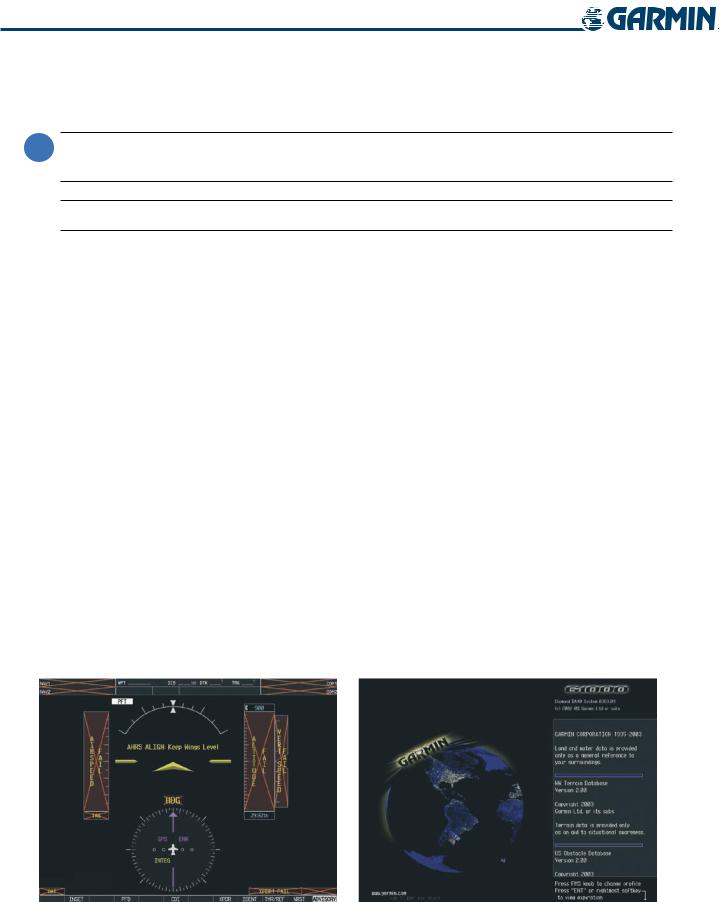
During system initialization, test annunciations are displayed, as shown in Figure 1-4. All system annunciations should disappear typically within the first minute of power-up. Upon power-up, key annunciator lights also become momentarily illuminated on the Audio Panel and the display bezels.
On the PFD, the AHRS begins to initialize and displays “AHRS ALIGN: Keep Wings Level”. The AHRS should display valid attitude and heading fields typically within the first minute of power-up. The AHRS can align itself both while taxiing and during level flight.
When the MFD powers up, the splash screen (Figure 1-5) displays the following information:
• System version |
• Obstacle database name and version |
• Copyright |
• Terrain database name and version |
• Land database name and version |
• Aviation database name, version, and effective dates |
Current database information includes valid operating dates, cycle number, and database type. When this information has been reviewed for currency (to ensure that no databases have expired), the pilot is prompted to continue.
Pressing the ENT Key (or right-most softkey) acknowledges this information, and the Navigation Map Page is displayed upon pressing the key a second time. When the system has acquired a sufficient number of satellites to determine a position, the aircraft’s current position is shown on the Navigation Map Page.
Figure 1-4 PFD Initialization |
Figure 1-5 MFD Power-Up Splash Screen |
1-8 |
Garmin G1000 Pilot’s Guide for the Diamond DA40/40F |
190-00592-02 Rev.A |
SYSTEM OVERVIEW
1.5 SYSTEM OPERATION
The displays are connected together via a single Ethernet bus for high-speed communication. As shown in Figure 1-1, each IAU is connected to the on-side display. Normal and reversionary G1000 display operation, as well as the various AHRS modes and G1000 System Annunciations are discussed here.
NORMAL DISPLAY OPERATION
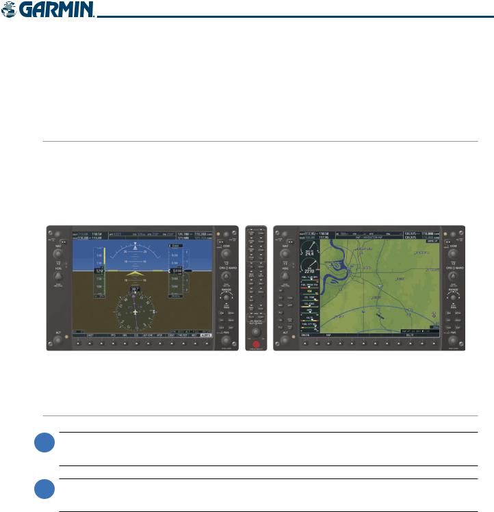
In normal operating mode, the PFD presents graphical flight instrumentation (attitude, heading, airspeed, altitude, vertical speed), replacing the traditional flight instrument cluster (see the Flight Instruments Section for more information). The MFD normally displays a full-color moving map with navigation information (see the GPS Navigation Section), while the left portion of the MFD is dedicated to the Engine Indication System (EIS; see the EIS Section). Both displays offer control for COM and NAV frequency selection.
Figure 1-6 G1000 Normal Operation
REVERSIONARY DISPLAY OPERATION
 NOTE: The G1000 System alerts the pilot when backup paths are utilized by the LRUs. Refer to Appendix A for further information regarding system-specific alerts.
 NOTE: In normal operating mode, backlighting can only be adjusted from the PFD. In Reversionary Mode, it can be adjusted from the remaining display.
In the event of a display failure, the G1000 System automatically switches to reversionary (backup) mode. In Reversionary Mode, all important flight information is presented on the remaining display in the same format as in normal operating mode.
If a display fails, the appropriate IAU-display Ethernet interface is cut off. Thus, the IAU can no longer communicate with the remaining display (refer to Figure 1-1), and the NAV and COM functions provided to the failed display by the IAU are flagged as invalid on the remaining display. The system reverts to backup paths for the AHRS, ADC, Engine/Airframe Unit, and Transponder, as required. The change to backup paths is completely automated for all LRUs and no pilot action is required.
190-00592-02 Rev.A |
Garmin G1000 Pilot’s Guide for the Diamond DA40/40F |
1-9 |

SYSTEM OVERVIEW
If the system fails to detect a display problem, Reversionary Mode may be manually activated by pressing the Audio Panel’s red DISPLAY BACKUP button. Pressing this button again deactivates Reversionary Mode.
NAV1 and COM1 (provided by the failed PFD) are flagged as invalid.
Pressing the DISPLAY BACKUP Button also  activates/deactivates Reversionary Mode.
Figure 1-7 G1000 Reversionary Mode (Failed PFD)
G1000 SYSTEM ANNUNCIATIONS
When an LRU or an LRU function fails, a large red ‘X’ is typically displayed over the instrument experiencing failed data (Figure 1-8 displays all possible flags and responsible LRUs). For a detailed description of all annunciations and alerts, refer to Appendix A. Refer to the Aircraft Flight Manual (AFM) for additional information regarding pilot responses to these annunciations.
Upon G1000 power-up, certain instruments remain invalid as equipment begins to initialize. All instruments should be operational within one minute of power-up. If any instrument remains flagged, the G1000 should be serviced by a Garmin-authorized repair facility.
GIA 63 |
|
|
|
|
|
GIA 63 |
|
|
|
|
|
||
|
|
|
|
|
GRS 77 or GMU 44 |
|
|
|
|
|
|
||
GEA 71
or 

 GDC 74 GIA 63
GIA 63
GTX 33 or GIA 63 GIA 63
GDC 74
Figure 1-8 G1000 System Failure Annunciations
1-10 |
Garmin G1000 Pilot’s Guide for the Diamond DA40/40F |
190-00592-02 Rev.A |
SYSTEM OVERVIEW
AHRS OPERATION
 NOTE: Aggressive maneuvering while AHRS is not operating normally may degrade AHRS accuracy.
The Attitude and Heading Reference System (AHRS) performs attitude, heading, and vertical acceleration calculations for the G1000 System, utilizing GPS, magnetometer, and air data in addition to information from its internal sensors. Attitude and heading information are updated on the PFD while the AHRS receives appropriate combinations of information from the external sensor inputs.
Loss of GPS, magnetometer, or air data inputs is communicated to the pilot by message advisory alerts (refer to Appendix A for specific AHRS alert information). Any failure of the internal AHRS inertial sensors results in loss of attitude and heading information (indicated by red ‘X’ flags over the corresponding flight instruments).
GPS INPUT FAILURE
Two GPS inputs are provided to the AHRS. If GPS information from one of the inputs fails, the AHRS uses the remaining GPS input and an alert message is issued to inform the pilot. If both GPS inputs fail, the AHRS can continue to provide attitude and heading information to the PFD as long as magnetometer and airspeed data are available and valid.
MAGNETOMETER FAILURE
If the magnetometer input fails, the AHRS continues to output valid attitude information; however, the heading output on the PFD is flagged as invalid with a red ‘X’.
AIR DATA INPUT FAILURE
Failure of the air data input has no effect on the AHRS output while AHRS is receiving valid GPS information. Invalid/unavailable airspeed data in addition to GPS failure results in loss of all attitude and heading information.
GPS
|
|
|
|
|
|
|
|
|
|
|
|
|
|
Magnetometer |
|||||
|
|
|
|
|
|
|
|||
|
|
|
|
Airspeed Data |
|||||
|
|
|
|
|
|
|
|
||
AHRS Normal |
AHRS no- |
AHRS no-Mag/ |
AHRS |
||||||
Mag Mode |
|
no-Air Mode |
no-GPS |
||||||
Operation |
Heading Invalid |
Mode |
|||||||
|
|
|
|||||||
|
|
|
|
|
|
|
|
|
|
|
|
|
|
|
|
|
|
|
|
|
|
|
|
|
|
|
|
|
|
|
|
|
|
|
|
|
|
|
|
|
|
|
|
|
|
|
|
|
|
|
|
|
|
|
|
|
|
|
|
�����������
Attitude/Heading Invalid
Figure 1-9 AHRS Operation
190-00592-02 Rev.A |
Garmin G1000 Pilot’s Guide for the Diamond DA40/40F |
1-11 |

SYSTEM OVERVIEW
GPS RECEIVER OPERATION
Each GIA 63 Integrated Avionics Unit (IAU) contains a GPS receiver. Information collected by the specified receiver (GPS1 for the #1 IAU or GPS2 for the #2 IAU) may be viewed on the AUX - GPS Status Page.
Viewing GPS receiver status information:
1)Use the large FMS Knob on the MFD to select the Auxiliary Page Group (see Section 1.7 for information on navigating MFD page groups).
2)Use the small FMS Knob to select GPS Status Page (third page in the AUX Page Group).
Selecting the GPS receiver for which data is displayed:
1)Use the FMS Knob to select the AUX - GPS Status Page.
2)To change the selected GPS receiver:
a)Press the desired GPS Softkey.
OR:
a)Press the MENU Key.
b)Use the FMS Knob to highlight the receiver which is not selected and press the ENT Key.
Satellite Constellation |
Satellite Signal |
Diagram |
Information Status |
GPS Receiver
Status
RAIM
Availability
Prediction
Satellite Signal
Strength Bars
Figure 1-10 GPS Status Page
1-12 |
Garmin G1000 Pilot’s Guide for the Diamond DA40/40F |
190-00592-02 Rev.A |

SYSTEM OVERVIEW
The GPS Status Page provides the following information:
• Satellite constellation diagram
Satellites currently in view are shown at their respective positions on a sky view diagram. The sky view is always in a north-up orientation, with the outer circle representing the horizon, the inner circle representing 45° above the horizon, and the center point showing the position directly overhead.
Each satellite is represented by an oval containing the Pseudo-random noise (PRN) number (i.e., satellite identification number). Satellites whose signals are currently being used are represented by solid ovals.
• Satellite signal information status
The accuracy of the aircraft’s GPS fix is calculated using Estimated Position Uncertainty (EPU), Dilution of Precision (DOP), and horizontal and vertical figures of merit (HFOM and VFOM). EPU is the radius of a circle centered on an estimated horizontal position in which actual position has 95% probability of laying. EPU is a statistical error indication and not an actual error measurement.
DOP measures satellite geometry quality (i.e., number of satellites received and where they are relative to each other) on a range from 0.0 to 9.9, with lower numbers denoting better accuracy. HFOM and VFOM, measures of horizontal and vertical position uncertainty, are the current 95% confidence horizontal and vertical accuracy values reported by the GPS receiver.
The current calculated GPS position, time, altitude, ground speed, and track for the aircraft are displayed below the satellite signal accuracy measurements.
• GPS receiver status
The GPS solution type (ACQUIRING, 2D NAV, 2D DIFF NAV, 3D NAV, 3D DIFF NAV) for the active GPS receiver (GPS1 or GPS2) is shown in the upper right of the GPS Status Page. When the receiver is in the process of acquiring enough satellite signals for navigation, the receiver uses satellite orbital data (collected continuously from the satellites) and last known position to determine the satellites that should be in view.
When the receiver is in the process of acquiring a 3D navigational GPS solution, 2D NAV is indicated as the solution since GPS altitude cannot be computed using the acquired satellite signal data. When differential GPS (DGPS) signals are available, the solution status is indicated as 2D DIFF NAV or 3D DIFF NAV.
• RAIM Prediction
Receiver Autonomous Integrity Monitoring (RAIM) is a GPS receiver function that performs a consistency check on all tracked satellites. RAIM ensures that the available satellite geometry allows the receiver to calculate a position within a specified RAIM protection limit (2.0 nautical miles for oceanic and enroute, 1.0 nm for terminal, and 0.3 nm for non-precision approaches). During oceanic, enroute, and terminal phases of flight, RAIM is available nearly 100% of the time.
The RAIM prediction function also indicates whether RAIM is available at a specified date and time. RAIM computations predict satellite coverage within ±15 min of the specified arrival date and time.
Because of the tighter protection limit on approaches, there may be times when RAIM is not available. The G1000 automatically monitors RAIM and warns with an alert message when it is not available. If RAIM is not predicted to be available for the final approach course, the approach does not become active, as indicated by the messages “Approach is not active” and “RAIM not available from FAF to MAP”. If RAIM is not available when crossing the FAF, the missed approach procedure must be flown.
190-00592-02 Rev.A |
Garmin G1000 Pilot’s Guide for the Diamond DA40/40F |
1-13 |

SYSTEM OVERVIEW
Predicting RAIM availability:
1)Select the GPS Status Page.
2)Press the FMS Knob. The ‘WAYPOINT’ field is highlighted.
3)Turn the small FMS Knob to display the Waypoint Information Window.
4)Enter the desired waypoint:
a)Use the FMS Knob to enter the desired waypoint by identifier,facility,or city name and press the ENT Key. Refer to Section 1.7 for instructions on entering alphanumeric data into the G1000.
OR:
a)Use the large FMS Knob to scroll to the Most Recent Waypoints List.
b)Use the small FMS Knob to highlight the desired waypoint in the list and press the ENT Key. The G1000 automatically fills in the identifier, facility, and city fields with the information for the selected waypoint.
c)Press the ENT Key to accept the waypoint entry.
OR:
a)To use the present position, press the MENU Key.
b)With ‘Set WPT to Present Position’ highlighted, press the ENT Key.
c)Press the ENT Key to accept the waypoint entry.
5)Use the FMS Knob to enter an arrival time and press the ENT Key.
6)Use the FMS Knob to enter an arrival date and press the ENT Key.
7)With the cursor highlighting ‘COMPUTE RAIM?’, press the ENT Key. Once RAIM availability is computed, one of the following is displayed:
•‘COMPUTE RAIM?’—RAIM has not been computed for the current waypoint, time, and date combination
•‘COMPUTING AVAILABILITY’—RAIM calculation in progress
•‘RAIM AVAILABLE’—RAIM is predicted to be available for the specified waypoint, time, and date
•‘RAIM NOT AVAILABLE’—RAIM is predicted to be unavailable for the specified waypoint, time, and date
•GPS Satellite Signal Strengths
The GPS Status Page can be helpful in troubleshooting weak (or missing) signal levels due to poor satellite coverage or installation problems. As the GPS receiver locks onto satellites, a signal strength bar is displayed for each satellite in view, with the appropriate satellite PRN number (01-32) below each bar. The progress of satellite acquisition is shown in three stages, as indicated by signal bar appearance:
-No signal strength bar—Receiver is looking for the indicated satellite
-Hollow signal strength bar—Receiver has found the satellite and is collecting data
-Solid signal strength bar—Receiver has collected the necessary data and the satellite signal can be used
-Checkered signal strength bar—Receiver has excluded the satellite (Fault Detection and Exclusion)
Each satellite has a 30-second data transmission that must be collected (signal strength bar is hollow) before the satellite may be used for navigation (signal strength bar becomes solid).
1-14 |
Garmin G1000 Pilot’s Guide for the Diamond DA40/40F |
190-00592-02 Rev.A |
SYSTEM OVERVIEW
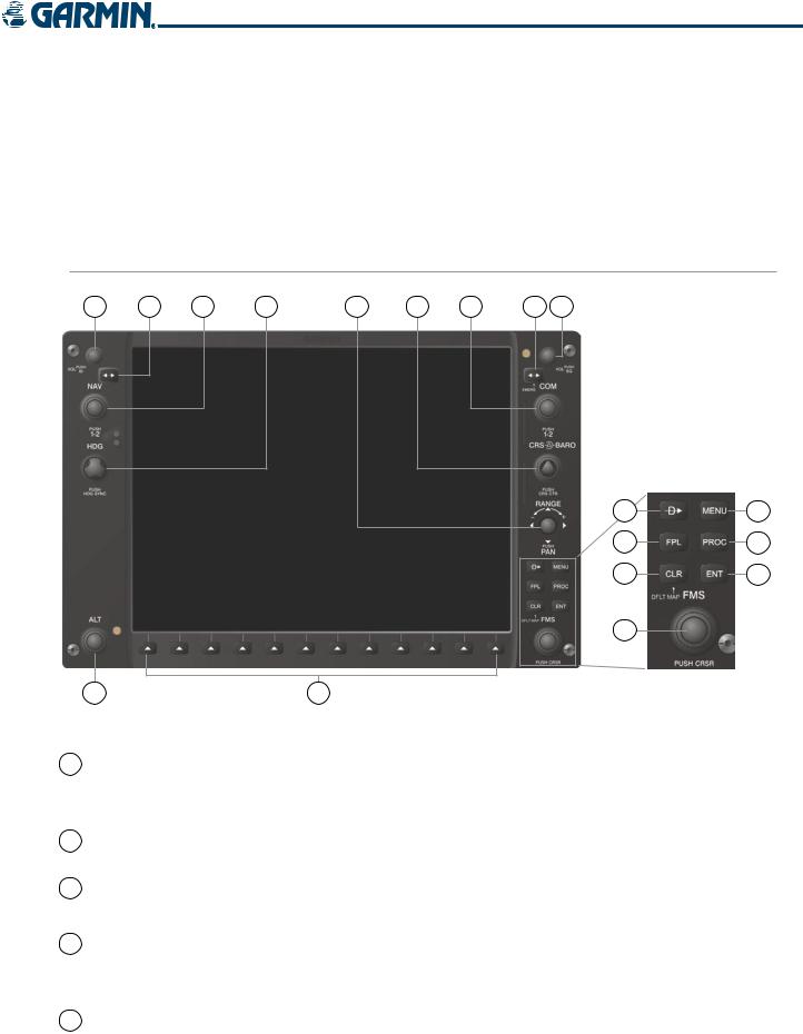
1.6 G1000 CONTROLS
The G1000 controls have been designed to simplify operation of the system and minimize workload and the time required to access sophisticated functionality. Controls are located on the PFD and MFD bezels and Audio Panel. PFD and MFD controls and softkeys are discussed in this section. See the Audio Panel and CNS Section for more information about Audio Panel and NAV/COM controls. AFCS controls (on the bezel of the MFD) are described in the AFCS section.
PFD/MFD CONTROLS
1 |
2 |
3 |
4 |
5 |
6 |
7 |
8 |
9 |
10 |
13 |
11 |
14 |
12 |
15 |
16 |
|
18 |
17 |
Figure 1-11 PFD/MFD Controls
1 NAV VOL/ID Knob Turn to control NAV audio volume (shown in the NAV Frequency Box as a percentage)
Press to toggle Morse code identifier audio on/off
2NAV Frequency Transfers the standby and active NAV frequencies
Transfer Key
3 |
NAV Knob |
Turn to tune NAV receiver standby frequencies (large knob for MHz; small for kHz) |
|
|
|
Press to toggle light blue tuning box between NAV1 and NAV2 |
|
4 |
Heading Knob |
Turn to manually select a heading |
|
|
|
Press to display a digital heading momentarily to the left of the Horizontal Situation |
|
|
|
Indicator (HSI) and synchronize the Selected Heading to the and current heading |
|
5 |
Joystick |
Turn to change map range |
|
|
|
Press to activate Map Pointer and move in desired direction to pan map |
|
190-00592-02 Rev.A |
Garmin G1000 Pilot’s Guide for the Diamond DA40/40F |
1-15 |
|

SYSTEM OVERVIEW
6 CRS/BARO Knob
7 COM Knob
8COM Frequency Transfer Key (EMERG)
Turn large knob for altimeter barometric pressure setting
Turn small knob to adjust course (only when HSI is in VOR or OBS Mode)
Press to re-center the CDI and return course pointer directly to bearing of active waypoint/station
Turn to tune COM transceiver standby frequencies (large knob for MHz; small for kHz)
Press to toggle light blue tuning box between COM1 and COM2
The selected COM (green) is controlled with the COM MIC Key (Audio Panel). Transfers the standby and active COM frequencies
Press and hold two seconds to tune the emergency frequency (121.5 MHz) automatically into the active frequency field
9 COM VOL/SQ Knob Turn to control COM audio volume level (shown as a percentage in the COM Frequency Box)
Press to turn the COM automatic squelch on/off
10Direct-to Key (
11FPL Key
12CLR Key (DFLT MAP)
13MENU Key
) Activates the direct-to function and allows the user to enter a destination waypoint and establish a direct course to the selected destination (specified by identifier, chosen from the active route)
Displays flight plan information
Erases information, cancels entries, or removes menus
Press and hold to display the MFD Navigation Map Page (MFD only).
Displaysacontext-sensitivelistofoptionsforaccessingadditionalfeaturesormaking setting changes
14 |
PROC Key |
Gives access to IFR departure procedures (DPs), arrival procedures (STARs), and |
|
|
approach procedures (IAPs) for a flight plan or selected airport |
15 |
ENT Key |
Validates/confirms selection or data entry |
16 |
FMS Knob |
Press to turn the selection cursor on/off |
|
(Flight Management Data Entry: With cursor on, turn to enter data in the highlighted field (large |
|
|
System Knob) |
knob moves cursor location; small knob selects character for highlighted cursor |
|
|
location) |
Scrolling: When a list of information is too long for the window/box, a scroll bar appears, indicating more items to view. With cursor on, turn large knob to scroll through the list.
Page Selection: Turn knob on MFD to select the page to view (large knob selects a page group; small knob selects a specific page from the group)
17Softkey Selection Press to select softkey shown above the bezel key on the PFD/MFD display
Keys
18 ALT Knob |
Sets the Selected Altitude, shown above the Altimeter (the large knob selects the |
|
|
thousands, the small knob selects the hundreds) |
|
1-16 |
Garmin G1000 Pilot’s Guide for the Diamond DA40/40F |
190-00592-02 Rev.A |
SYSTEM OVERVIEW
The NAV, CRS/BARO, COM, FMS, and ALT knobs are concentric dual knobs, each having small (inner) and large (outer) control portion. When a portion of the knob is not specified in the text, either may be used.
Large (Outer)
Knob
Small (Inner)
Knob
Figure 1-12 Dual Concentric Knob
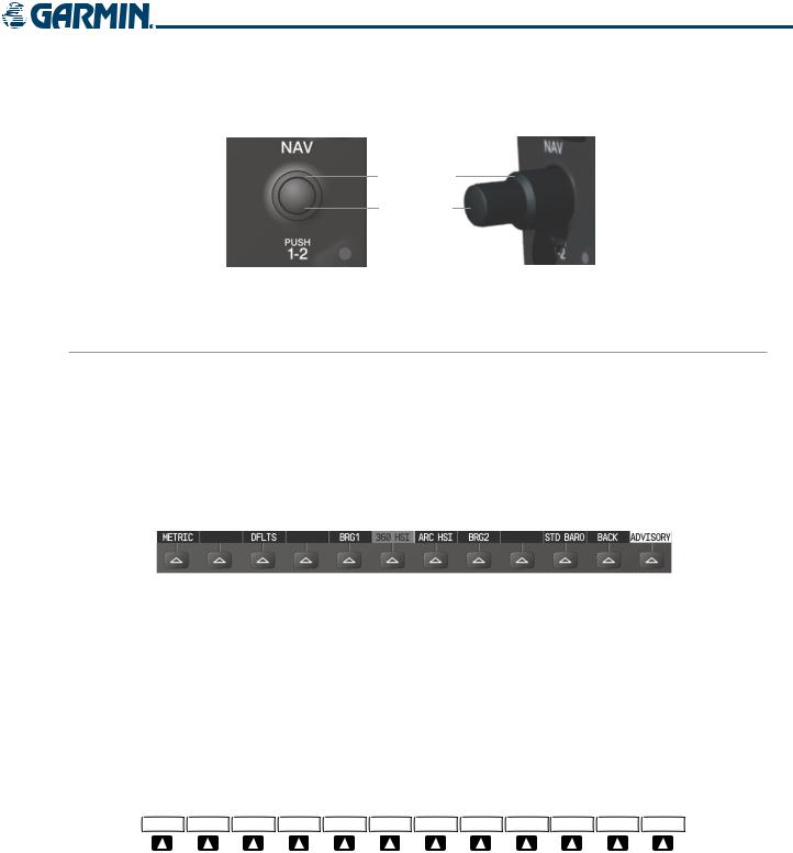
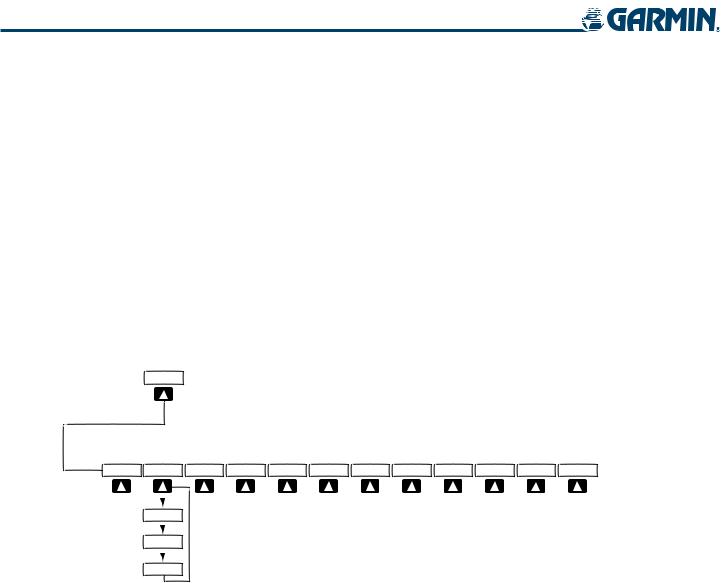
SOFTKEY FUNCTION
The softkeys are located along the bottoms of the displays. The softkeys shown depend on the softkey level or page being displayed. The bezel keys below the softkeys can be used to select the appropriate softkey. When a softkey is selected, its color changes to black text on gray background and remains this way until it is turned off, at which time it reverts to white text on black background.
In the following descriptions, top level softkeys are denoted with bullets.
|
|
Softkey |
|
Softkey Selection |
|||
|
|
On |
|
Box (Light Blue) |
|||
|
|
|
|
|
|
|
Softkey Names |
|
|
|
|
|
|
|
|
Bezel-Mounted |
|
|
|
(Displayed) |
|||
|
|
|
|
||||
Softkeys (Press) |
|
Figure 1-13 Softkeys (Second-Level PFD Configuration) |
|||||
|
|
||||||
PFD SOFTKEYS
The CDI, IDENT, TMR/REF, NRST, and ALERTS softkeys undergo a momentary change to black text on gray background and automatically switch back to white text on black background when selected.
The PFD softkeys provide control over flight management functions, including GPS, NAV, terrain, traffic, and lightning (optional). Each softkey sublevel has a BACK Softkey which can be selected to return to the previous level. The ALERTS Softkey is visible at all softkey levels (label changes if messages are issued).
|
|
|
|
(optional) |
|
INSET |
PFD |
OBS |
CDI |
ADF/DME XPDR |
IDENT TMR/REF NRST ALERTS |
Press the CDI Softkey to cycle through navigation sources:
- GPS
- NAV1 (VOR/LOC)
- NAV2 (VOR/LOC)
Figure 1-14 Top-level PFD Softkeys
190-00592-02 Rev.A |
Garmin G1000 Pilot’s Guide for the Diamond DA40/40F |
1-17 |
SYSTEM OVERVIEW
• INSET |
Displays Inset Map in PFD lower left corner |
OFF |
Removes Inset Map |
DCLTR (3) |
Selects desired amount of map detail; cycles through declutter levels: |
|
DCLTR (No Declutter): All map features visible |
|
DCLTR-1: Removes land data |
|
DCLTR-2: Removes land and SUA data |
|
DCLTR-3: Removes everything except active flight plan |
TRAFFIC |
Displays/removes traffic information on Inset Map |
TOPO |
Displays/removes topographical data (e.g., coastlines, terrain, rivers, lakes) on Inset Map |
TERRAIN |
Displays/removes terrain information on Inset Map |
NEXRAD |
Displays/removes NEXRAD weather and coverage information on Inset Map (optional) |
XM LTNG |
Displays/removes XM lightning information on Inset Map (optional) |
|
INSET |
|
|
|
(optional) (optional) |
|
OFF |
DCLTR |
TRAFFIC TOPO TERRAIN |
NEXRAD XM LTNG |
BACK ALERTS |
DCLTR-1
DCLTR-2
DCLTR-3
Press the OFF or BACK Softkey to return to the top-level softkeys.
Figure 1-15 INSET Softkeys
• PFD |
Displays second-level softkeys for additional PFD configuration |
METRIC |
Displays Selected and current altitudes additionally in meters and changes barometric |
|
setting to hectopascals (hPa) from inches of mercury (in Hg) |
DFLTS |
Resets PFD to default settings, including changing units to standard |
DME |
Displays/removes DME Information Window (optional) |
BRG1 |
Cycles the Bearing 1 Information Window through: |
|
NAV1: Waypoint frequency/identifier and DME information |
|
GPS: Waypoint identifier and GPS distance information |
|
ADF: Waypoint frequency |
|
Off: Removes window |
360 HSI |
Displays the HSI as a 360° compass rose |
ARC HSI |
Displays the HSI as a 140° viewable arc (Bearing Information Windows unavailable) |
1-18 |
Garmin G1000 Pilot’s Guide for the Diamond DA40/40F |
190-00592-02 Rev.A |
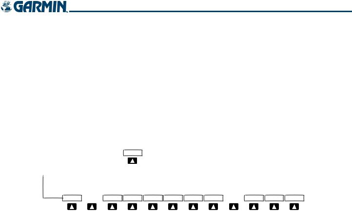
SYSTEM OVERVIEW
BRG2 |
Cycles the Bearing 2 Information Window through: |
|
NAV2: Waypoint frequency/identifier and DME information |
|
GPS: Waypoint identifier and GPS distance information |
|
ADF: Waypoint frequency |
|
Off: Removes window |
STD BARO |
Sets barometric pressure to 29.92 in Hg (1013 hPa if METRIC Softkey is selected) |
• OBS |
Selects OBS Mode on the CDI when navigating by GPS (only available with active leg) |
• CDI |
Cycles CDI through GPS, NAV1 (VOR/LOC), and NAV2 (VOR/LOC) navigation sources |
• ADF/DME Displays/removes ADF/DME Radio Tuning Window (optional; may appear as ADF, DME, or
ADF/DME depending on installation)
PFD
(optional)
METRIC  DFLTS DME BRG1 360 HSI ARC HSI BRG2
  STD BARO BACK ALERTS
|
Press the BRG1/BRG2 softkeys to display/ |
|
remove the Bearing Information windows |
|
and cycle through bearing sources: |
|
- NAV1/NAV2 |
|
- GPS |
|
- ADF |
|
Press the STD BARO or BACK Softkey |
|
to return to the top-level softkeys. |
|
Figure 1-16 PFD Configuration Softkeys |
• XPDR |
Displays transponder mode selection softkeys: |
STBY |
Selects standby mode (Transponder does not reply to any interrogations) |
ON |
Selects Mode A (Transponder replies to interrogations) |
ALT |
Selects Mode C – altitude reporting mode (Transponder replies to identification and altitude |
|
interrogations) |
VFR |
Automatically enters the VFR code (1200 in U.S.A. only) |
CODE |
Displays transponder code selection softkeys 0-7 |
0 — 7 |
Use numbers to enter code |
BKSP |
Removes numbers entered, one at a time |
•IDENT Activates the Special Position Identification (SPI) pulse for 18 seconds, identifying the transponder return on the ATC screen
•TMR/REF Displays/removes Timer/References Window
•NRST Displays/removes Nearest Airports Window
•ALERTS Displays/removes Alerts Window
190-00592-02 Rev.A |
Garmin G1000 Pilot’s Guide for the Diamond DA40/40F |
1-19 |
SYSTEM OVERVIEW
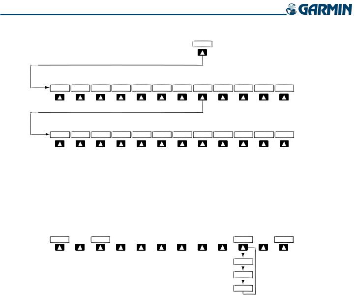
XPDR
STBY |
ON |
ALT |
VFR |
CODE |
IDENT |
BACK ALERTS |
Press the BACK Softkey to return to the top-level softkeys.
0 |
1 |
2 |
3 |
4 |
5 |
6 |
7 |
IDENT |
BKSP |
BACK ALERTS |
Press the IDENT or BACK Softkey to return to the top-level softkeys.
Figure 1-17 XPDR Softkeys
MFD SOFTKEYS
MFD softkeys vary depending on the page selected. EIS and Navigation Map Page (default MFD page) softkeys are described here.
ENGINE  MAP
MAP 

 DCLTR
DCLTR  CHKLIST
DCLTR-1
DCLTR-2
DCLTR-3
Figure 1-18 Navigation Map Page Softkeys
• ENGINE Displays second-level engine softkeys (Figure 1-19; see the EIS Section for more information)
LEAN Displays the EIS Lean Display (softkeys for engine leaning assist are shown when selected) SYSTEM Displays the EIS System Display (softkeys for fuel calculations are shown when selected)
• MAP Enables second-level Navigation Map Page softkeys TRAFFIC Displays/removes traffic information on Navigation Map Page
TOPO Displays/removes topographical data (e.g., coastlines, terrain, rivers, lakes) on Navigation Map Page
TERRAIN Displays/removes terrain information on Navigation Map Page
NEXRAD Displays/removes NEXRAD weather and coverage information on Navigation Map Page (optional)
XM LTNG Displays/removes XM lightning information on Navigation Map Page (optional) BACK Returns to top-level softkeys
1-20 |
Garmin G1000 Pilot’s Guide for the Diamond DA40/40F |
190-00592-02 Rev.A |
 Loading...