


 Loading...
Instructions for Continued Airworthiness & Maintenance Manual,
GDL 82 Mooney M20( ) Series STC
Aircraft make, model, registration number, and serial number and accompanying STC configuration information in Appendix A must be completed and retained with aircraft permanent records.
190-01810-11 |
September 2019 |
Revision 2 |

©2019 Garmin International or its subsidiaries All Rights Reserved
Except as expressly provided herein, no part of this manual may be reproduced, copied, transmitted, disseminated, downloaded or stored in any storage medium, for any purpose without the express prior written consent of Garmin. Garmin hereby grants permission to download a single copy of this manual and of any revision to this manual onto a hard drive or other electronic storage medium to be viewed and to print one copy of this manual or of any revision hereto, provided such electronic or printed copy of this manual or revision must contain the complete text of this copyright notice and provided further any unauthorized commercial distribution of this manual or any revision hereto is strictly prohibited.
Garmin®, flyGarmin®, and GDL® are registered trademarks of Garmin International or its subsidiaries. The GDL 82™ and GTN™ are trademarks of Garmin International or its subsidiaries. These trademarks may not be used without the express permission of Garmin.
Windows® is a registered trademark of Microsoft Corporation in the United States and other countries.
All other product or company names that may be mentioned in this publication are trade names, trademarks, or registered trademarks of their respective owners.
At Garmin, we value your opinion. For comments about this guide please e-mail: Techpubs.Salem@garmin.com.
For information regarding the Aviation Limited Warranty, refer to Garmin’s website.
Garmin International, Inc. 1200 E. 151st Street Olathe, KS 66062 USA Telephone: (913) 397-8200
Aviation Dealer Technical Support Line (Toll Free): (828) 606-5482 www.garmin.com
www.flyGarmin.com
Garmin AT, Inc.
2345 Turner Rd. SE
Salem, OR 97302 USA
Telephone: (503) 581-8101
ICA/MM, GDL 82 Mooney M20( ) Series STC |
190-01810-11 |
|
Rev. 2 |
|
Page i |

|
|
RECORD OF REVISIONS |
|
|
|
Revision |
Revision Date |
Description |
|
|
|
1 |
12/14/2017 |
Initial Release |
|
|
|
2 |
09/23/2019 |
Update to add GPS 175/GNC 355 as GPS sources, and to update main |
|
|
board and GPS/GBAS board software versions (non-functional) |
|
|
|
ICA/MM, GDL 82 Mooney M20( ) Series STC |
190-01810-11 |
|
Rev. 2 |
|
Page ii |
INFORMATION SUBJECT TO EXPORT CONTROL LAWS
This document may contain information which is subject to the Export Administration Regulations (“EAR”) issued by the United States Department of Commerce (15 CFR, Chapter VII, Subchapter C) and which may not be exported, released, or disclosed to foreign nationals inside or outside of the United States without first obtaining an export license. A violation of the EAR may be subject to a penalty of up to 10 years imprisonment and a fine of up to $1,000,000 under Section 2410 of the Export Administration Act of 1979. Include this notice with any reproduced portion of this document.
DEFINITIONS OF WARNINGS, CAUTIONS, AND NOTES
WARNING
Warnings indicates that personal injury or death is possible if the instructions are not obeyed.
CAUTION
Cautions are used to alert that damage to equipment may result if the procedural step is not followed.
NOTE
Notes provide further information about preceding steps and/or reasons for the particular operation.
WARNING
This product, its packaging, and its components contain chemicals known to the State of California to cause cancer, birth defects, or reproductive harm. This notice is being provided in accordance with California's Proposition 65. If you have any questions or would like additional information, please refer to our web site at www.garmin.com/prop65.
NOTE
All screen shots used in this document are current at the time of publication. Screen shots are intended to provide visual reference only. All information depicted in screen shots, including software file names, versions, and part numbers, is subject to change and may not be up to date.
ICA/MM, GDL 82 Mooney M20( ) Series STC |
190-01810-11 |
|
Rev. 2 |
|
Page iii |

|
|
TABLE OF CONTENTS |
|
SECTION ........................................................................................................................................... |
PAGE |
||
1 |
INTRODUCTION ................................................................................................................................... |
1 |
|
|
1.1 |
Introduction...................................................................................................................................... |
1 |
|
1.2 |
Organization..................................................................................................................................... |
1 |
|
1.3 |
Acronyms and Abbreviations .......................................................................................................... |
1 |
|
1.4 |
Publications...................................................................................................................................... |
2 |
|
1.5 |
Revision and Distribution ................................................................................................................ |
2 |
2 |
SYSTEM DESCRIPTION....................................................................................................................... |
3 |
|
3 |
CONTROL & OPERATION................................................................................................................... |
4 |
|
|
3.1 |
GDL 82 Install Tool......................................................................................................................... |
4 |
4 |
INSTRUCTIONS FOR CONTINUED AIRWORTHINESS .................................................................. |
8 |
|
|
4.1 |
Airworthiness Limitations ............................................................................................................... |
8 |
|
4.2 |
Servicing Information ...................................................................................................................... |
8 |
|
4.3 |
Maintenance Intervals...................................................................................................................... |
9 |
|
4.4 |
Visual Inspection ........................................................................................................................... |
10 |
|
4.5 |
Electrical Bonding Test.................................................................................................................. |
11 |
5 |
TROUBLESHOOTING ........................................................................................................................ |
12 |
|
|
5.1 |
General........................................................................................................................................... |
12 |
|
5.2 |
ADS-B OUT FAIL Annunciator ................................................................................................... |
14 |
|
5.3 |
GDL 82 Install Tool....................................................................................................................... |
14 |
|
5.4 |
GDL 82 Data Logging ................................................................................................................... |
16 |
|
5.5 |
GDL 82 Connector Pinout ............................................................................................................. |
17 |
6 |
EQUIPMENT REMOVAL & INSTALLATION ................................................................................. |
18 |
|
|
6.1 |
GDL 82 Unit .................................................................................................................................. |
18 |
|
6.2 |
Annunciator and Switch................................................................................................................. |
18 |
|
6.3 |
GPS Antenna.................................................................................................................................. |
19 |
|
6.4 |
Transponder Antenna..................................................................................................................... |
19 |
7 |
EQUIPMENT CONFIGURATION & CHECKOUT............................................................................ |
20 |
|
|
7.1 |
System Checkout ........................................................................................................................... |
20 |
|
7.2 |
GDL 82 Configuration................................................................................................................... |
20 |
|
7.3 |
GDL 82 Post-Installation Test Procedures..................................................................................... |
21 |
8 |
RETURN TO SERVICE PROCEDURE............................................................................................... |
21 |
|
|
8.1 |
Maintenance Records..................................................................................................................... |
21 |
ICA/MM, GDL 82 Mooney M20( ) Series STC |
190-01810-11 |
|
Rev. 2 |
|
Page iv |

FIGURES |
|
FIGURE |
PAGE |
Figure 2-1: GDL 82 System I/O Interfaces...................................................................................... |
3 |
Figure 3-1: USB A and USB B Connectors..................................................................................... |
4 |
Figure 3-2: GDL 8X Install Tool Selection ..................................................................................... |
4 |
Figure 3-3: GDL 82 Unit Information Page..................................................................................... |
5 |
Figure 3-4: GDL 82 Software Upload Page..................................................................................... |
6 |
Figure 3-5: GDL 82 System Configuration Page............................................................................. |
7 |
Figure 5-1: GDL 82 Install Tool, Faults Page ............................................................................... |
15 |
Figure 5-2: GDL 82 Install Tool, GPS Page .................................................................................. |
15 |
Figure 5-3: GDL 82 Install Tool, GPS Sat Status Page ................................................................. |
16 |
Figure 5-4: GDL 82 Install Tool, Assert Log Page........................................................................ |
16 |
Figure 5-5: Rear View, Connector J821 ........................................................................................ |
17 |
TABLES |
|
TABLE |
PAGE |
Table 1-1: Recommended Documents............................................................................................ |
2 |
Table 4-1: Maintenance Intervals .................................................................................................... |
9 |
Table 5-1: General Troubleshooting Guide ................................................................................... |
12 |
Table 5-2: System Faults Troubleshooting Guide ......................................................................... |
13 |
Table 5-3: J821 Pinout ................................................................................................................... |
17 |
ICA/MM, GDL 82 Mooney M20( ) Series STC |
190-01810-11 |
|
Rev. 2 |
|
Page v |

1 INTRODUCTION
1.1Introduction
This document provides Instructions for Continued Airworthiness (ICA) and Maintenance Manual (MM) for the Garmin GDL 82 UAT Transmitter as installed in Mooney M20() Series aircraft under STC SA02573SE. This document satisfies the requirements for continued airworthiness as defined by 14 CFR Part 23.1529 and Appendix G. Information in this document is required to maintain the continued airworthiness of the GDL 82.
1.2Organization
The following outline briefly describes the organization of this manual:
Section 2: System Description
Provides a complete description of the type design change associated with installing the GDL 82. An overview of the system interface is also provided.
Section 3: Control & Operation
Presents basic control and operation information related to maintenance of the GDL 82.
Section 4: Instructions for Continued Airworthiness
Provides maintenance instructions for continued airworthiness of the GDL 82.
Section 5: Troubleshooting
Provides troubleshooting information to aid in diagnosing and resolving potential problems with the GDL 82.
Section 6: Equipment Removal & Installation
Contains instructions for the removal and installation of the GDL 82.
Section 7: Equipment Configuration & Checkout
Contains instructions for configuring and testing the GDL 82 after reinstallation or replacement.
Section 8: Return to Service Procedure
Specifies return-to-service procedures required after completion of the GDL 82 maintenance.
Appendix A: Installation Specific Information
Provides a template to record general installation information and the system configuration log for a specific installation of the GDL 82.
1.3Acronyms and Abbreviations
The following acronyms are used in this manual:
AC |
Advisory Circular |
ICA |
Instructions for Continued Airworthiness |
|
ADS-B |
Automatic Dependent Surveillance – |
ICAO |
International Civil Aviation Organization |
|
Broadcast |
||||
|
|
|
||
AFM |
Airplane Flight Manual |
I/O |
Input / Output |
|
AFMS |
Airplane Flight Manual Supplement |
IM |
Installation Manual |
|
ALT |
Altitude |
MM |
Maintenance Manual |
|
ATC |
Air Traffic Control |
PC |
Personal Computer |
|
CFR |
Code of Federal Regulations |
POH |
Pilot Operating Handbook |
|
DC |
Direct Current |
SBAS |
Satellite-Based Augmentation System |
ICA/MM, GDL 82 Mooney M20( ) Series STC |
190-01810-11 |
|
Rev. 2 |
|
Page 1 |

ELA |
Electrical Load Analysis |
STC |
EMC |
Electromagnetic Checkout |
SW |
FAA |
Federal Aviation Administration |
UAT |
GDL |
Garmin Datalink Transceiver |
USB |
GNS |
Garmin Navigator Series |
Vs0 |
GPS |
Global Positioning System |
XPDR |
GTN |
Garmin Touch Navigator |
|
Supplemental Type Certificate Software
Universal Access Transceiver Universal Serial Bus
Aircraft Stall Speed (in landing configuration)
Transponder
1.4Publications
When performing GDL 82 system maintenance it is recommended the following documents are available.
|
|
Table 1-1: Recommended Documents |
|
|
|
Part Number |
Garmin Document |
|
|
|
|
190-01810-03 |
GDL 82 |
Pilot's Quick Start Guide |
|
|
|
190-01810-10 |
GDL 82 |
Mooney M20() Series STC Installation Manual |
|
|
|
190-01810-12 |
Airplane Flight Manual Supplement for the GDL 82 Mooney M20 Series |
|
|
|
|
1.5Revision and Distribution
This document is required for maintaining the continued airworthiness of the aircraft. When this document is revised, every page will be revised to indicate current revision level.
Owner/operators may obtain the latest revision of this document at www.flyGarmin.com or by contacting a Garmin dealer. Garmin contact information is available at www.flyGarmin.com.
ICA/MM, GDL 82 Mooney M20( ) Series STC |
190-01810-11 |
|
Rev. 2 |
|
Page 2 |

2 SYSTEM DESCRIPTION
The GDL 82 is a remote-mounted unit that contains 978 MHz and 1030 MHz transmitters, and a 1090 MHz receiver. It is installed in-line with the existing transponder and L-Band antenna. The GDL 82 transmits ownship ADS-B Out data via the UAT data link using the existing transponder’s L-Band antenna. The GDL 82 utilizes the direct in-line connection to synchronize with the aircraft transponder via 1030 MHz interrogations to obtain the transponder Squawk (Mode 3/A) code, IDENT status and pressure altitude.
ADS-B equipment requires GPS/SBAS data for ADS-B Out transmissions. Only the GPS/SBAS data sources specified in the GDL 82 Mooney M20() Series STC Installation Manual, 190-01810-10, are approved by this STC to interface with the GDL 82.
The GDL 82 uses the following interfaces:
•Aircraft Power and Ground
•Transponder Coaxial Connection
•L-Band Coaxial Connection
•GPS Coaxial Connection – Used only for internal GPS source
•1 RS-232 I/O – Used only for external GPS source
•1 Discrete Output – Failure Annunciator (optional)
•2 Discrete Inputs – Anonymous Mode Switch and Squat Switch (optional)
•USB Interface – Configuring GDL 82 and Loading Software from PC
The GDL 82 System Interface Diagram is shown in Figure 2-1.
GDL 82
Bottom L-Band Antenna
Transponder |
Coax |
|
|
Power/Ground |
|
OPTIONAL |
|
Failure |
Discrete |
Annunciator |
|
Anonymous |
Discrete |
Mode Switch |
|
Squat/WOW |
Discrete |
Switch |
|
Coax |
|
|
GPS Antenna |
Coax |
|
(GDL 82 with GPS only) |
|
|
OR |
RS-232 |
|
GPS Time Mark |
GPS Source |
|
|
USB |
PC Config |
|
Tool |
Figure 2-1: GDL 82 System I/O Interfaces
ICA/MM, GDL 82 Mooney M20( ) Series STC |
190-01810-11 |
|
Rev. 2 |
|
Page 3 |
3 CONTROL & OPERATION
The GDL 82 user control interface is limited to ADS-B OUT FAIL annunciator and the UAT ANONYMOUS mode switch, installation of either or both is optional. The primary ADS-B Out UAT transmit function of the GDL 82 does not require direct user input.
Refer to the GDL 82 Pilot’s Quick Start Guide, 190-01810-03, and the Airplane Flight Manual Supplement for the GDL 82 Mooney M20 Series, 190-01810-12, for control and operation information.
3.1GDL 82 Install Tool
The GDL 8X Install Tool (Garmin Part Number: 006-A0248-20) allows for configuration, diagnostics, and software loading. The tool is available for download from the Garmin Dealer Resource Center and flyGarmin.com. The GDL 8X Install Tool requires a computer with Microsoft Windows XP or later and an available USB 2.0 port.
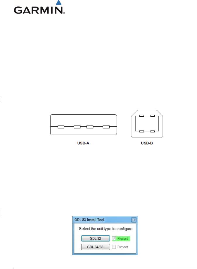
A USB A-to-B cable is required to interface between a computer and the GDL 82, refer to Figure 3-1 for details.
Figure 3-1: USB A and USB B Connectors
The GDL 82 Install Tool provides access to the following functions -
•Diagnostics – reports device information, faults, interface status and other information for post installation checkout procedures. It also allows the unit assert log to be saved and cleared.
•Configuration – allows selection of installation options.
•System Update – allows upload of software to the GDL 82 unit.
To utilize the GDL 82 Install Tool, first disconnect power from the GDL 82, and then connect the USB cable. Restore power to the GDL 82, and then run the GDL 8X Install Tool.
The GDL 8X Install Tool will automatically detect which unit it is interfaced with (e.g., GDL 82 or GDL 84/88). To use the GDL 82 Install Tool verify that the GDL 82 unit is checked Present and select the GDL 82 button. See Figure 3-2.
Figure 3-2: GDL 8X Install Tool Selection
ICA/MM, GDL 82 Mooney M20( ) Series STC |
190-01810-11 |
|
Rev. 2 |
|
Page 4 |

NOTE
When the GDL 82 unit is connected to the PC (via USB) and the GDL 8X Install Tool is active, the GDL 82 will automatically be placed in Configuration Mode. To reset the GDL 82 into Normal Mode, power down the unit, disconnect it from the USB and reapply power to the GDL 82.
3.1.1Device Information
The Unit Information page, displays product information such as the model, part number, serial numbers, software version and software part numbers to be viewed.
Figure 3-3: GDL 82 Unit Information Page
The other Diagnostics pages are used during post-installation checkout and troubleshooting. See Section 5.3 for details.
ICA/MM, GDL 82 Mooney M20( ) Series STC |
190-01810-11 |
|
Rev. 2 |
|
Page 5 |
Loading...