


 Loading...
GMA 342/345
Installation Manual
190-01878-02 |
November, 2020 |
Revision 5 |
© 2020
Garmin Ltd. or its subsidiaries All Rights Reserved
Except as expressly provided herein, no part of this manual may be reproduced, copied, transmitted, disseminated, downloaded or stored in any storage medium, for any purpose without theexpresspriorwrittenconsentofGarmin.Garminherebygrantspermissiontodownloadasingle copy of this manualand of anyrevisiontothis manual onto ahard drive or other electronic storage medium to be viewed and to print one copy of this manual or of any revision hereto, provided that such electronic or printed copy of this manual or revision must contain the complete text of this copyrightnoticeandprovidedfurtherthatanyunauthorizedcommercialdistributionofthismanual or any revision hereto is strictly prohibited.
©2017 The Bluetooth® word mark and logos are registered trademarks owned by Bluetooth SIG, Inc. and any use of such marks by Garmin is under license. Other trademarks and trade names are those of their respective owners.
Garmin International, Inc.
1200 E. 151st Street
Olathe, KS 66062 USA
Aviation Panel-Mount Technical Support Line (Toll Free) 1.888.606.5482
Garmin (Europe) Ltd.
Liberty House, Hounsdown Business Park
Southampton, Hampshire SO40 9LR U.K.
Garmin aviation support and warranty information can be found at www.flygarmin.com. |
||
|
|
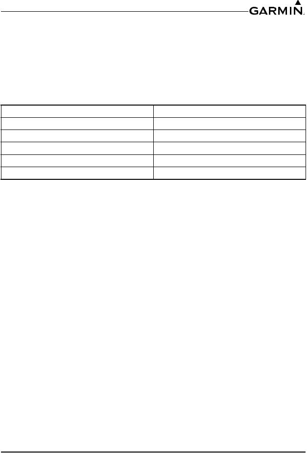
RECORD OF REVISIONS |
Revision |
Revision Date |
Description |
1 |
01/17/17 |
Initial Release |
209/18/17 Updated Transmitter Grant of Equipment Authorization info
304/05/18 Updated Post Installation Checkout Procedure, added 3-COM unit info
409/17/19 Added missing pin info to Table 4-2
511/25/20 Added RS-232 pin info
190-01878-02 |
GMA 342/345 Installation Manual |
Rev. 5 |
Page A |
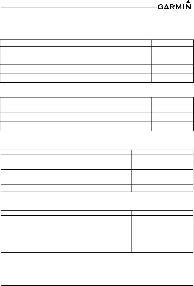
CURRENT REVISION DESCRIPTION
Revision |
Page |
Section |
Description of Change |
|
Number |
Number |
|||
|
|
|||
|
4-3 |
4.2.2 |
Added RS-232 pin info |
|
5 |
4-5 |
4.5 |
Added RS-232 pin info |
|
C-3, C-8, |
|
Added RS-232 pin info to Figure C-3, Figure C-8, and |
||
|
Appdx C |
|||
|
C-9 |
Figure C-9 |
||
|
|
INFORMATION SUBJECT TO EXPORT CONTROL LAWS
This document may contain information which is subject to the Export Administration Regulations ("EAR") issued by the United States Department of Commerce (15 CFR, Chapter VII, Subchapter C) and which may not be exported, released, or disclosed to foreign nationals inside or outside of the United States without first obtaining an export license. The preceding statement is required to be included on any and all reproductions in whole or in part of this manual.
DEFINITIONS OF WARNINGS, CAUTIONS, AND NOTES
WARNING
This product, its packaging, and its components contain chemicals known to the State of California to cause cancer, birth defects, or reproductive harm. This Notice is being provided in accordance with California's Proposition 65. If you have any questions or would like additional information, please refer to our web site at www.garmin.com/prop65.
NOTE
Unless otherwise noted, information listed for the GMA 345 also applies to the GMA 345 3-COM version unit.
190-01878-02 |
GMA 342/345 Installation Manual |
Rev. 5 |
Page i |

SOFTWARE LICENSE AGREEMENT
BY USING THE DEVICE, COMPONENT OR SYSTEM MANUFACTURED OR SOLD BY GARMIN (“THE GARMIN PRODUCT”), YOU AGREE TO BE BOUND BY THE TERMS AND CONDITIONS OF THE FOLLOWING SOFTWARE LICENSE AGREEMENT. PLEASE READ THIS AGREEMENT CAREFULLY. Garmin Ltd. and its subsidiaries (“Garmin”) grants you a limited license to use the software embedded in the Garmin Product (the “Software”) in binary executable form in the normal operation of the Garmin Product. Title, ownership rights, and intellectual property rights in and to the Software remain with Garmin and/or its third-party providers. You acknowledge that the Software is the property of Garmin and/or its third-party providers and is protected under the United States of America copyright laws and international copyright treaties. You further acknowledge that the structure, organization, and code of the Software are valuable trade secrets of Garmin and/or its third-party providers and that the Software in source code form remains a valuable trade secret of Garmin and/or its third-party providers. You agree not to reproduce, decompile, disassemble, modify, reverse assemble, reverse engineer, or reduce to human readable form the Software or any part thereof or create any derivative works based on the Software. You agree not to export or re-export the Software to any country in violation of the export control laws of the United States of America.
190-01878-02 |
GMA 342/345 Installation Manual |
Rev. 5 |
Page ii |

TABLE OF CONTENTS
PARAGRAPH PAGE
Section 1 General Description |
...........................................................................1-1 |
|
1.1 |
Introduction...................................................................................................................... |
1-1 |
1.2 |
Equipment Description.................................................................................................... |
1-1 |
1.3 |
Technical Specifications.................................................................................................. |
1-3 |
1.4 |
Certification..................................................................................................................... |
1-7 |
1.5 |
Operating Instructions.................................................................................................... |
1-10 |
1.6 |
Reference Documents.................................................................................................... |
1-10 |
Section 2 Installation Overview......................................................................... |
2-1 |
|
2.1 |
Introduction...................................................................................................................... |
2-1 |
2.2 |
Installation Materials ....................................................................................................... |
2-1 |
2.3 |
Available Accessories...................................................................................................... |
2-2 |
2.4 |
Installation Considerations .............................................................................................. |
2-4 |
2.5 |
Cabling and Wiring.......................................................................................................... |
2-7 |
2.6 |
Electrical Bonding ........................................................................................................... |
2-7 |
2.7 |
Cooling Air...................................................................................................................... |
2-8 |
2.8 |
Configuration, and Adjustment Options.......................................................................... |
2-8 |
2.9 |
Updating Software......................................................................................................... |
2-13 |
2.10 Electrical Noise............................................................................................................ |
2-14 |
|
2.11 Mounting Requirements .............................................................................................. |
2-15 |
|
Section 3 Installation Procedure........................................................................ |
3-1 |
|
3.1 |
Unpacking Unit................................................................................................................ |
3-1 |
3.2 |
Electrical Connections..................................................................................................... |
3-1 |
3.3 |
Antenna Installation......................................................................................................... |
3-2 |
3.4 |
Shield Block Backshell Installation Instructions............................................................. |
3-2 |
3.5 |
Backshell Assembly......................................................................................................... |
3-3 |
3.6 |
Unit Installation ............................................................................................................... |
3-3 |
3.7 |
Post Installation Checkout.............................................................................................. |
3-4 |
3.8 |
Continued Airworthiness................................................................................................. |
3-7 |
3.9 |
Diagnostics Information .................................................................................................. |
3-7 |
3.10 Disabling Bluetooth Connectivity (GMA 345 only) ..................................................... |
3-8 |
|
Section 4 System Interconnects ......................................................................... |
4-1 |
|
4.1 |
Connector Description..................................................................................................... |
4-1 |
4.2 |
Pin List............................................................................................................................. |
4-1 |
4.3 |
Aircraft Power.................................................................................................................. |
4-4 |
4.4 |
Lighting Bus .................................................................................................................... |
4-5 |
4.5 |
RS-232............................................................................................................................. |
4-5 |
190-01878-02 |
GMA 342/345 Installation Manual |
Rev. 5 |
Page iii |

PARAGRAPH |
PAGE |
|
4.6 |
Audio Inputs/Outputs and Mic Keys |
...............................................................................4-5 |
4.7 |
Discrete Inputs............................................................................................................... |
4-12 |
4.8 |
Marker Beacon............................................................................................................... |
4-12 |
Appendix A |
Installation Considerations for Upgrading from a |
|
|
|
|
Garmin GMA 340 ........................................................................ |
A-1 |
A.1 |
Mechanical Considerations............................................................................................ |
A-1 |
|
A.2 |
Electrical Considerations............................................................................................... |
A-1 |
|
A.3 |
GMA 340 to GMA 342/345 Retrofit Connections........................................................ |
A-2 |
|
Appendix B |
Outline and Installation Drawings ............................................. |
B-1 |
|
Appendix C |
Interconnect Drawings................................................................. |
C-1 |
|
190-01878-02 |
GMA 342/345 Installation Manual |
Rev. 5 |
Page iv |

1 GENERAL DESCRIPTION
1.1 Introduction
This manual is intended to provide mechanical and electrical information for use in the planning and design of an installation of the GMA 342/345 into an aircraft. This manual is not a substitute for an approved airframe-specific maintenance manual, installation design drawing, or complete installation data package. Attempting to install equipment by reference to this manual alone and without first planning or designing an installation specific to your aircraft may compromise your safety and is not recommended. The content of this manual assumes use by competent and qualified avionics engineering personnel and/or avionics installation specialists using standard aviation maintenance practices in accordance with Title 14 of the Code of Federal Regulations and other relevant accepted practices. This manual is not intended for use by individuals who do not possess the competencies and abilities set forth above.
NOTE
Garmin recommends installation of the GMA 342/345 by a Garmin-authorized installer. To the extent allowable by law, Garmin will not be liable for damages resulting from improper or negligent installation of the GMA 342/345. For questions, please contact Garmin Aviation Product Support at 1-888-606-5482.
1.2 Equipment Description
The Garmin GMA 342/345 Audio Panels are TSO-certified products and have received FAA approval.
The GMA 342/345 units are high-fidelity digital audio panels that collect, process, and distribute audio signals to crew and passengers. The GMA 342/345 digital signal processing (DSP) core filters the audio signals and provides digital audio routing to minimize noise.
The GMA 342/345 provides a speaker output for use as a cockpit speaker. Both also include a cockpit voice recorder and playback feature to help in situations where a COM transmission may need to be heard again. The GMA 345 includes a Bluetooth® transceiver for listening to music and making phone calls, or sending headset audio to a VIRB XE, and a 10 Watt USB charge port for phones and tablets. The GMA 342 does not have Bluetooth capability and includes an available front panel 3.5 mm jack for plugging in phones or tablets for music audio or cell phone calls.
Other features include intuitive configuration, a lighting bus input, SD Card socket for code loads and Bluetooth firmware updates (only GMA 345 has Bluetooth capability), an 8 position DIP switch for installation settings, and multiple audio switching functions. LED-illuminated push-buttons allow audio selection and annunciation for selection of NAV, COM, and other audio. Photocell dimming circuitry automatically adjusts the brightness of the annunciators, with backlighting controlled by the aircraft lighting bus. A fail-safe circuit connects the pilot's headset and microphone directly to COM 1 and a failsafe warning audio input in the event that power is interrupted or the unit is turned off.
The GMA 345 has 2 music inputs in addition to the Bluetooth transceiver, NAV, COM, and ICS selections. The GMA 342 has 2 music inputs in addition to the front panel 3.5 mm jack, NAV, COM, and ICS selections. Both the GMA 345 and GMA 342 are easily configurable without an external PC connection. Both GMA 345 and GMA 342 have automatic intercom squelch and optional keyed intercom squelch. These audio panels were designed to be drop in replacements for the GMA 340, and do not interface or integrate to any system. The standard (2-COM) version of these audio panels only support two COMs, however a 3-COMversion of the GMA 345 (011-03520-20) is alsoavailable. For installationsthat require more than 2 COMs the recommended audio panel is the GMA 345 3-COM, GMA 350H, or GMA 350Hc.
190-01878-02 |
GMA 342/345 Installation Manual |
Rev. 5 |
Page 1-1 |
NOTE
Unless otherwise noted, information listed for the GMA 345 also applies to the GMA 345 3-COM version unit.
1.2.1Features Summary
Table 1-1 GMA 342/345 Features Summary
Feature
Bluetooth Transceiver USB Charge Port
3.5 mm 4-Conductor Jack Input
Tranceiver Channels
Receiver Inputs
Microphone Inputs
Microphone Keys
Music Inputs (rear connector)
Alert Inputs (unswitched) Speaker Output Headset Outputs Discrete Inputs Discrete Outputs Failsafe Channel Lighting Bus
SD Card Socket
8 Position DIP Switch
GMA 342 |
GMA 345 |
GMA 345 3-COM |
None |
1 - Not shared with Music 1 or Music 2 |
|
None |
|
1 |
1 - not shared with |
None |
|
Music 1 or Music 2 |
||
|
||
3 - COM 1, COM 2, TEL |
4 - COM 1, COM 2, |
|
COM 3, TEL |
||
|
5 - NAV 1, NAV 2, 5 - NAV 1, NAV 2, AUX 1, AUX 2, AUX 3* AUX 1, AUX 2,
AUX 3 **
6 - Pilot, Copilot, 4 Passenger
2 - Pilot, Copilot
2
4
1
3 - Pilot, Copilot, Passenger (passenger output can drive 4 headsets) 5 3
1 - Only Heard During Power Off Mode
1
1
1
*Note that two buttons (AUX1 and AUX 2) are used to select/deselect the 3 AUX inputs. Pressing the AUX 1 button selects/deselects the AUX 1 and AUX 3 receivers. Pressing the AUX2 button selects/ deselects the AUX 2 receiver.
**Note that one button (AUX) is used to select/deselect all 3 AUX inputs. When AUX is selected, audio from all three AUX inputs is merged and heard together.
190-01878-02 |
GMA 342/345 Installation Manual |
Rev. 5 |
Page 1-2 |
1.3 Technical Specifications
It is the responsibility of the installing agency to obtain the latest revision of the GMA 34X Environmental Qualification Form. This form is available directly from Garmin under the following part number:
GMA 34X Environmental Qualification Form, Garmin part number 005-00880-01
To obtain a copy of this form, see the dealer/OEM portion of the Garmin web site (www.garmin.com).
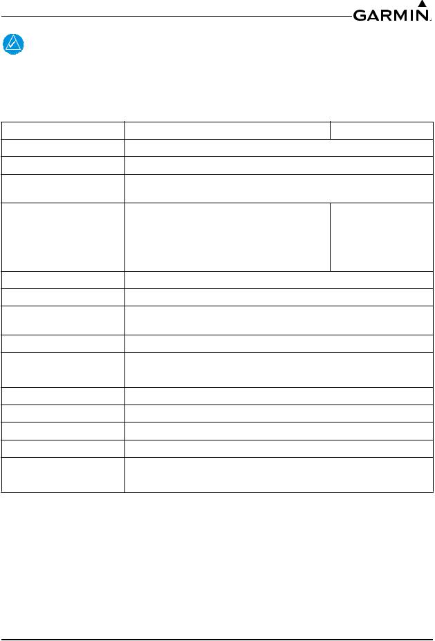
1.3.1Physical Characteristics
Table 1-2 Physical Characteristics GMA 342/345
Characteristic |
Specification |
Bezel Height
Bezel Width
Rack Height (Dimple to Dimple) Rack Width
Depth Behind Panel with Connectors (measured from face of aircraft panel to rear of connector backshells)
GMA 342/345 Weight (Unit Only)
GMA 342/345 Weight (Installed with rack, backplate, and connectors)
1.30 inches (33.0 mm)
6.30 inches (160.0 mm)
1.33 inches (34.0 mm)
6.30 inches (160.0 mm)
8.09 inches (205.0 mm)
1.10 lbs (0.49 kg)
1.78 lbs (0.81 kg)
190-01878-02 |
GMA 342/345 Installation Manual |
Rev. 5 |
Page 1-3 |

1.3.2Electrical Specifications
Table 1-3 Electrical Characteristics
Characteristic
Environmental
Compliance
Software
Compliance
Maximum Absolute
Audio Delay
Altitude
Maximum Days of
Continuous
Operation
Audio Panel
Functions
Intercom Functions
Headphone
Outputs
Specification
RTCA DO-160F
RTCA DO-178B Level D
The Input to Output delay is less than 1.1 ms for all audio I/O excluding entertainment audio (Music, Telephone, and Bluetooth)
55,000 Feet Overpressure - 15,000 Feet
49
Dedicated Transceiver inputs: 3 (including TEL) for GMA 342 and 345, 4 (including TEL) for GMA 345 3-COM unit
Dedicated Receiver inputs: 5 (per notes in Table 1-1 regarding which AUX inputs are uniquely selectable)
Alert (unswitched) inputs: 4 (each with configurable volume) Input impedance: 600 Ω
Input isolation: 60 dB minimum Alert/Receiver/Transceiver bandwidth: 100 Hz to 6.5 kHz Special functions: Fail-safe operation
All inputs use MASQ™ processing (Master Avionics Squelch) Max input 5 Vrms
Positions: 6 - Pilot, Copilot, 4 Passengers
Volume controls: 4 (Pilot ICS, Pilot Music, Copilot/Passenger ICS, Copilot/Passenger Music)
Microphone input impedance: 150 Ω (compatible with 150 to 600 Ω mics) Microphone bias voltage: 11 Vdc delivered through 470 Ω
Intercom isolation modes: 3 - Pilot, Crew, and All
Telephone interfaces: 1 full-duplex (use rear LRU pins or Bluetooth transceiver)
ICS Auto-Squelch/VOX: Independent DSP (digital signal processing) determined thresholds for each mic.
Note that keyed intercom is optional. Auto-squelch not available when using keyed ICS.
Output amplifiers: 3 Stereo - Pilot, Copilot, Passengers Power, Load, and Distortion: 65 mW into 150 Ohms with <10% THD+N @ 10% output <3% THD+N
Typical Operating Distortion: <1% THD+N
3dB Frequency Response Bandwidth: 20 Hz to 20 kHz for Music 350 Hz to 6.5 kHz for Other Audio (MICs, Radios, Alerts)
190-01878-02 |
GMA 342/345 Installation Manual |
Rev. 5 |
Page 1-4 |
Characteristic
Music Functions
Bluetooth
Connectivity GMA 345 only
USB Charge Port GMA 345 only
3.5 mm
Front Panel Jack GMA 342 only
Marker Beacon
Receiver
Table 1-3 Electrical Characteristics
Specification
Music inputs (stereo): 2
Music input impedance: 600 Ω (differential) Music gain: +24dB @ max. volume
Music input level:<200 mVrms for full power* output @ max music volume knob position (typ.)
3.0 Vrms max music input level
Music bandwidth: 20 Hz to 20 kHz @ full power output
Music distortion: <0.1% THD+N (typ.) @ full power, full bandwidth *Full power output refers to 65 mW into 150 Ω at the headset
Bluetooth 3.00 Compliant, allows music, cell phone calls, and interface with the VIRB XE action camera. Bluetooth capability supports HFP (including HFP v1.6 Wide Band Speech mode), A2DP, and AVRCP.
The GMA 345 stores 10 paired devices and overwrites the least recently connected device when a new device is paired. Only 1 Bluetooth connection allowed at one time. The VIRB XE cannot be connected when using a phone (and vice versa).
USB charge port - Rated for 10 W. The GMA 345 charge port features USB port detection that will connect the optimum charge rate for the device connected. The charge port supports a maximum of 2.1 Amp charge current for devices. The USB charge port will shutdown and protect the GMA 345 for current draw above 2.3 Amps.
The GMA 342 has a standard 3.5 mm front panel jack for connecting by cable phones or tablets. The front panel allows stereo music to be played from a device, and also allows cell phone calls to be made through the GMA 342. The front panel jack is a 4 conductor jack, allowing either a standard 3 conductor plug for audio, and also 4 conductor plugs used by some cell phones for phone calls.
For stereo music input, the jack is rated to 1.5 Vrms and has 5 kohm input impedance.
Frequency: Crystal controlled at 75 MHz Sensitivity: LO 1000 μV hard; HI 200 μV hard
Selectivity: 6 dB @ ±10 kHz min, 40 dB @ ±200 kHz max. Input impedance: 50Ω
External lamp drive: 125 mA max each output Other outputs: Middle MKR sense
Special functions: SmartMuteTM marker audio muting
190-01878-02 |
GMA 342/345 Installation Manual |
Rev. 5 |
Page 1-5 |

Table 1-4 Speaker Output
Aircraft Voltage |
Speaker Impedance |
Output Power |
|
14V |
4 Ω |
3 Watts |
|
8 Ω |
Not Recommended |
||
|
|||
28V |
4 Ω |
10 Watts |
|
8 Ω |
7 Watts |
||
|
1.3.3Power Requirements
The GMA 342/345 will operate down to emergency voltage (9 Volts). Below 11 Volts, the USB charge port (GMA 345 only) and the speaker (both GMA 342 and GMA 345) are disabled.
Table 1-5 GMA 342/345 Power Requirements
Characteristic |
Specification |
Input Voltage Range |
11 to 33 Vdc |
Leakage Current* |
< 1 mA |
*Current the unit draws when turned off (GMA 342/345 turned off by the knob).
Table 1-6 GMA 342 Power Requirements
Characteristic |
Current Draw |
Power Consumption |
|
Idle Current* |
0.34 A @ 14 VDC |
4.76 W @ 14 VDC |
|
0.19 A @ 28 VDC |
5.32 W @ 28 VDC |
||
|
|||
Typical Operating Current |
0.83 A @ 14 VDC |
11.62 W @ 14 VDC |
|
0.43 A @ 28 VDC |
12.04 W @ 28 VDC |
||
|
|||
Maximum Current |
1.19 A @ 14 VDC |
16.66 W @ 14 VDC |
|
0.90 A @ 28 VDC |
25.20 W @ 28 VDC |
||
|
*Unit current drawn with power applied, no audio, and minimum lighting.
Table 1-7 GMA 345 Power Requirements
Characteristic
Idle Current*
Typical Operating Current without USB charge port being used.
Maximum Current with no USB charge port connection
Maximum Current with USB charge port connection
Current Draw |
Power Consumption |
0.34 A @ 14 VDC |
4.76 W @ 14 VDC |
0.19 A @ 28 VDC |
5.32 W @ 28 VDC |
0.83 A @ 14 VDC |
11.62 W @ 14 VDC |
0.43 A @ 28 VDC |
12.04 W @ 28 VDC |
1.19 A @ 14 VDC |
16.66 W @ 14 VDC |
0.90 A @ 28 VDC |
25.20 W @ 28 VDC |
2.39 A @ 14 VDC |
33.46 W @ 14 VDC |
1.49 A @ 28 VDC |
41.72 W @ 28 VDC |
*Unit current drawn with power applied, no audio, and minimum lighting.
190-01878-02 |
GMA 342/345 Installation Manual |
Rev. 5 |
Page 1-6 |

1.4 Certification
The conditions and tests required for TSO approval of this article are minimum performance standards. It is the responsibility of those installing this article either on or within a specific type or class of aircraft to determine that the aircraft installation conditions are within the TSO standards. TSO articles must have separate approval for installation in an aircraft. The article may be installed only if performed under 14 CFR part 43 or the applicable airworthiness requirements.
The GMA 345 and GMA 342 have been shown to meet compliance with the claimed TSO(s) when interfaced with the equipment defined in this installation manual, and installed in accordance with the requirements and limitations as defined in this installation manual.
The Appliance Project Identifier (API) for the GMA 342 and GMA 345 is GMN-01319. The API has been used for project identification with the FAA. See applicable hardware and software part numbers to identify appliance approvals.
1.4.1TSO Compliance
Table 1-8 GMA 342/345 (011-03520-00 and 011-03520-10) TSO Compliance
|
TSO/ETSO/ |
|
Applicable LRU |
Applicable LRU |
|
Function |
Category |
Software Part |
Boot Block Part |
||
RTCA/EUROCAE |
|||||
|
|
Numbers |
Numbers |
||
|
|
|
|||
AirborneRadioMarker |
TSO-C35d |
A |
|
|
|
Receiving Equipment |
DO-143 |
|
|
||
|
All |
All |
|||
Aircraft Audio |
|
|
|||
TSO-C139a |
|
006-B2227-0( ) |
006-B2227-B( ) |
||
Systems and |
Class Ib |
|
|
||
DO-214A |
|
|
|||
Equipment |
|
|
|
||
|
|
|
|
Table 1-9 GMA 345 (011-03520-20) TSO Compliance
|
TSO/ETSO/ |
|
Applicable LRU |
Applicable LRU |
|
Function |
Category |
Software Part |
Boot Block Part |
||
RTCA/EUROCAE |
|||||
|
|
Numbers |
Numbers |
||
|
|
|
|||
AirborneRadioMarker |
TSO-C35d |
A |
All |
|
|
Receiving Equipment |
DO-143 |
006-B2227-0() |
|
||
|
|
||||
Aircraft Audio |
|
|
except |
All |
|
TSO-C139a |
|
006-B2227-00 |
006-B2227-B( ) |
||
Systems and |
Class Ib |
and |
|
||
DO-214A |
|
||||
Equipment |
|
006-B2227-01 |
|
||
|
|
|
190-01878-02 |
GMA 342/345 Installation Manual |
Rev. 5 |
Page 1-7 |

1.4.2TSO Deviations
Table 1-10 GMA 342/345 (011-03520-00, 011-03520-10, 011-03520-20) TSO Deviations
TSO |
Deviation |
|
Garmin received a deviation from TSO-C35d to not permanently and legibly marking |
|
the unit with each TSO’s required information. |
|
Garmin received a deviation from TSO-C35d to use FAR §45.15(b) instead of FAR |
TSO-C35d |
§37.7(d) as the general rules governing holders of the TSO authorizations. |
|
Garmin received a deviation from TSO-C35d to use RTCA DO-160F instead of RTCA |
|
DO-138 as the standard for Environmental Conditions and Test Procedures for |
|
Airborne Equipment. |
190-01878-02 |
GMA 342/345 Installation Manual |
Rev. 5 |
Page 1-8 |

1.4.3Transmitter Grant of Equipment Authorization
1. FCC
GMA 345 Contains FCC ID: QOQWT32I
NOTE
This device complies with Part 15 of the FCC Rules. Operation is subject to the following two conditions:
(1) this device may not cause harmful interference, and (2) this device must accept any interference received, including interference that may cause undesired operation.
FCC RF Radiation Exposure Statement:
This equipment complies with FCC radiation exposure limits set forth for an uncontrolled environment. End users must follow the specific operating instructions for satisfying RF exposure compliance. This transmitter meets both portable and mobile limits as demonstrated in the RF Exposure Analysis. This transmitter must not be co-located or operating in conjunction with any other antenna or transmitter except in accordance with FCC multi-transmitter product procedures.
2. IC
GMA 345 Contains IC: 5123A-BGTWT32I
NOTE
This device complies with Innovation, Science and Economic Development Canada license-exempt RSS standard(s). Operation is subject to the following two conditions: (1) this device may not cause interference, and (2) this device must accept any interference, including interference that may cause undesired operation of the device.
Cet appareil est conforme aux normes RSS sans licence du ministére Innovation, Sciences et Développement économique Canada. Son fonctionnement est soumis aux deux conditions suivantes : (1) ce périphérique ne doit pas causer d’interférences et (2) doit accepter toute interférence, y compris les interférences pouvant entraîner un fonctionnement indésirable de l’appareil.
3. Declaration of Conformity (GMA 345)
Hereby, Garmin declares that this product is in compliance with the Directive 2014/53/EU. The full text of the EU declaration of conformity is available at the following internet address: www.garmin.com/compliance.
Radio frequency/protocol (GMA 345): Bluetooth® wireless technology 2.4 GHz @ -0.49 dBm nominal
190-01878-02 |
GMA 342/345 Installation Manual |
Rev. 5 |
Page 1-9 |
1.5 Operating Instructions
For operating instructions, refer to the applicable GMA 342 Pilot’s Guide (190-01878-00), GMA 345 Pilot’s Guide (190-01878-01), or GMA 345 3-COM Pilot’s Guide (190-01878-05).
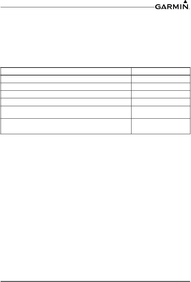
1.6 Reference Documents
The following publications are sources of additional information for installing the GMA 342/345. The installer should read all referenced materials along with this manual before attempting installation.
Table 1-11 Reference Documents
Part Number |
|
Document |
190-00149-01 |
GMA 340 |
Installation Manual |
190-00313-09 |
Shield Block Installation Instructions |
|
190-01878-00 |
GMA 342 |
Pilot’s Guide |
190-01878-01 |
GMA 345 |
Pilot’s Guide |
190-01878-05 |
GMA 345 |
3-COM Pilot’s Guide |
190-01878-02 |
GMA 342/345 Installation Manual |
Rev. 5 |
Page 1-10 |

2 INSTALLATION OVERVIEW
2.1 Introduction
This section provides the necessary information for the installation and checkout of the GMA 342/345 Audio Panel. Installation of the GMA 342/345 will differ according to equipment location and other factors. The appendices contain interconnect wiring diagrams, mounting dimensions, and information pertaining to installation.
Careful planning and consideration of the suggestions in this section are required to achieve the desired performance andreliabilityfromthe GMA 342/345. The guidance of FAA advisory circularsAC 43.13-1B and AC 43.13-2B, where applicable, may be found useful for making retro-fit installations that comply with FAA regulations.
2.2 Installation Materials
2.2.1Unit Configurations
Table 2-1 Catalog Part Numbers
Model
GMA 342 Unit Only
GMA 342 Standard Kit (includes items in Table 2-2)
GMA 345 Unit Only
GMA 345 Standard (includes items in Table 2-3)
GMA 345 3-COM Unit Only
GMA 345 3-COM Standard (includes items in Table 2-3)
Catalog Part Number |
Unit Only Part Number |
010-01319-10 |
011-03520-10 |
010-01319-11 |
011-03520-10 |
010-01319-00 |
011-03520-00 |
010-01319-01 |
011-03520-00 |
010-01319-20 |
011-03520-20 |
010-01319-21 |
011-03520-20 |
190-01878-02 |
GMA 342/345 Installation Manual |
Rev. 5 |
Page 2-1 |
2.3 Available Accessories
2.3.1Standard Accessories
Table 2-2 Contents of GMA 342 Standard Installation Kit
Item |
Part Number |
Sub-Assy, Back Plate, GMA 342/345 (also used for GMA 240/340) (Table 2-4) |
011-00678-00 |
Conn Kit, GMA 342/345 (also used for GMA 35/350) (Table 2-5) |
011-02302-00 |
Sub -Assy, Audio Cables, 3.5 mm Right Angle |
011-02412-00 |
SMP, Install Rack, GMA 342/345 (also used for GMA 240/340) |
115-00262-00 |
Table 2-3 Contents of GMA 345 Standard Installation Kit
Item |
Part Number |
Sub-Assy, Back Plate, GMA 342/345 (also used for GMA 240/340) (Table 2-4) |
011-00678-00 |
Conn Kit, GMA 342/345 (also used for GMA 35/350) (Table 2-5) |
011-02302-00 |
SMP, Install Rack, GMA 342/345 (also used for GMA 240/340) |
115-00262-00 |
Table 2-4 Contents of GMA 342/345 Back Plate Kit (011-00678-00, also used for GMA 240/340)
Item |
Part Number |
Quantity |
Pre-bagged screws “D” (Table 2-6) |
011-02650-03 |
1 |
Nut Cover, SMP |
115-00261-00 |
1 |
Connector Plate Assembly, DCP |
125-00040-00 |
1 |
Nut, Std, English, SS, #6-32 |
210-00036-07 |
1 |
Screw, 4-40 x 0.250, PHP, SS/P, w/NYL |
211-60234-08 |
2 |
Table 2-5 Contents of GMA 342/345 Conn Kit (011-02302-00, also used for GMA 35/350)
Item |
Part Number |
Quantity |
Backshell w/Hardware 44 pin |
011-00950-02 |
2 |
Ground Adapter, Shell 1-3 |
011-01169-00 |
4 |
Screw 4-40 x 0.437, FLHP100, SS/P, Nylon |
211-63234-11 |
4 |
Hi Density D-Sub Connector, Mil Crimp, 44 ckt |
330-00185-44 |
2 |
Contact Pin, Mil Crimp, Size 22D |
336-00021-00 |
94 |
190-01878-02 |
GMA 342/345 Installation Manual |
Rev. 5 |
Page 2-2 |

Table 2-6 Contents of GMA 342/345 Pre-bagged Screws “D” (011-02650-03)
Item |
Part Number |
Quantity |
Screw, 4-40 x 0.250, PHP, SS/P, w/NYL |
211-60234-08 |
4 |
Cable Tie, 4.0” |
231-10001-00 |
1 |
Table 2-7 Contents of GMA 342 Sub-Assy, Audio Cables, 3.5mm RA (011-02412-00)
Item |
Part Number |
Quantity |
Cable Assembly, Audio, 3.5mm to 3.5mm, Right Angle, 4 Pole Plug |
320-00571-00 |
1 |
Cable Assembly, Audio, 3.5mm to 2.5mm, Right Angle, 4 Pole Plug |
320-00571-01 |
1 |
2.3.2Additional Equipment Required
•Cables: The installer will fabricate and supply all system cables. Interconnect wiring diagrams are detailed in Appendix C.
•Hardware: #6-32 100° flat head screw (6 ea.) and #6-32 self-locking nut (6 ea.). Hardware required to mount the GMA342/345 installation rack is not provided.
•Stereo headphone jacks (up to 6), microphone jacks (up to 6), 3.5mm stereo jacks (up to 2). Insulating type jacksor insulating washers should be used for all jacks to isolate them from aircraft chassis.
•Tool: 3/32"Allen for tightening the unit into the rack and backplate.
•Push/Pull (that can be manually reset) circuit breaker (5Amp recommended).
•Tie Wraps or Lacing Cord
•Ring Terminals (for grounding) #8 size, Yellow, Blue, and Pink.
•Silicon Fusion Tape (GPN 249-00114-00) to wrap the cable bundle.
•Solder Sleeves for terminating the shields of the cable to the GMA342/345 backshell. See 190-00313-09 for part numbers.
•Heat shrink tubing
•SD card needed for updating software in the GMA342/345. Garmin recommends using a 4 GB Sandisk® SD card.
Insulating Washers for Headset and Microphone Jacks can be found at the following suppliers:
Dallas Avionics |
Digi-key |
100053 - Shoulder Washer |
SC1147-ND - Shoulder Washer |
100054 - Flat Washer |
SC1146-ND - Flat Washer |
Mouser |
Newark |
502-S-1029 – Shoulder Washer |
S1029 - Shoulder Washer |
502-S-1028 – Flat Washer |
S1028 - Flat Washer |
Switchcraft |
|
S1029 – Shoulder Washer |
|
S1028 – Flat Washer |
|
190-01878-02 |
GMA 342/345 Installation Manual |
Rev. 5 |
Page 2-3 |

2.4 Installation Considerations
The GMA342/345interfaces with variousavionics equipment. Fabricationof a wiringharnessis required. Sound mechanical and electrical methods and practices are required for installation of the GMA342/345.
NOTE
3D audio is not available when using a mono headset or in aircraft wired with mono headset jacks. 3D audio (even if enabled), will not be available with mono audio headset jacks or mono headsets. It is recommended that stereo jacks and stereo headsets be used.
2.4.1Auxiliary Inputs
For the GMA 345 3-COM unit, a single AUX button is used to select all 3 AUX inputs for simultaneous monitoring.
For the GMA 342 and 345 (2-COM version), two buttons (AUX1 and AUX2) are used to select/deselect the 3 AUX inputs. Pressing the AUX1 button selects/deselects the AUX 1 and AUX 3 receivers. Pressing the AUX2 button selects/deselects the AUX 2 receiver.
NOTE
It is important to consider what sources are wired to the AUX 1 and AUX 3 inputs because when AUX 1 is selected, both AUX 1 and AUX 3 receiver audio will be heard together (this note is not applicable to the GMA 345 3-COM unit).
190-01878-02 |
GMA 342/345 Installation Manual |
Rev. 5 |
Page 2-4 |
Loading...