


 Loading...
G5 Electronic Flight Instrument
Pilot's Guide
for Non-Certified Aircraft
Blank Page

SYSTEM OVERVIEW
FLIGHT INSTRUMENTS
AFCS
ADDITIONAL FEATURES
INDEX
Blank Page
© 2017 Garmin Ltd. or its subsidiaries. All rights reserved.
This manual reflects the operation of System Software version 4.10 or later. Some differences in operation may be observed when comparing the information in this manual to earlier or later software versions.
Garmin International, Inc., 1200 East 151st Street, Olathe, Kansas 66062, U.S.A.
Garmin AT, Inc.,2345 Turner Road SE, Salem, OR 97302, U.S.A.
Garmin (Europe) Ltd., Liberty House, Hounsdown Business Park, Southampton, Hampshire SO40 9LR U.K.
Garmin Corporation, No. 68, Zhangshu 2nd Road, Xizhi District, New Taipei City, Taiwan
Web Site Address: www.garmin.com
Except as expressly provided herein, no part of this manual may be reproduced, copied, transmitted, disseminated, downloaded or stored in any storage medium, for any purpose without the express written permission of Garmin. Garmin hereby grants permission to download a single copy of this manual and of any revision to this manual onto a hard drive or other electronic storage medium to be viewed for personal use, provided that such electronic or printed copy
of this manual or revision must contain the complete text of this copyright notice and provided further that any unauthorized commercial distribution of this manual or any revision hereto is strictly prohibited.
Garmin® is a registered trademark of Garmin Ltd. or its subsidiaries. This trademark may not be used without the express permission of Garmin.
October, 2017 |
190-02072-00 Rev. G |
Printed in the U.S.A. |
Warnings, Cautions & Notes
BATTERY WARNINGS:
If these guidelines are not followed, the lithium-ion battery may experience a shortened life span or may present a risk of damage to the device, fire, chemical burn, electrolyte leak, and/or injury.
•Do not leave the battery exposed to a heat source or in a high temperature environment. To help prevent damage, store the battery out of direct sunlight.
•For maximum battery longevity, store within a temperature range of -4˚F to 68˚F (from -20˚C to 20˚C).
•Do not use a sharp object to remove the battery.
•Do not disassemble, puncture, damage, or incinerate the device or battery.
•Keep the battery away from children.
•Only replace the battery with the approved replacement from Garmin. Using another battery presents a risk of fire or explosion. To purchase a replacement battery, see you Garmin dealer or the Garmin website.
•Contact your local waste disposal department to dispose of the device and battery in accordance with applicable local laws and regulations.
WARNING: To reduce the risk of unsafe operation, carefully review and understand all aspects of the G5 Install Manual & Pilot's Guide documentation and the Pilot’s Operating Handbook of the aircraft.Thoroughly practice basic operation prior to actual use. During flight operations, carefully compare indications from the G5 to all available flight displays. For safety purposes, always resolve any discrepancies.
WARNING: The altitude calculated by the G5 internal GPS receiver is geometric height above Mean Sea Level and could vary significantly from the altitude displayed by pressure altimeters. Always use the pressure altitude display, when available, for determining or selecting aircraft altitude.
WARNING: The United States government operates the Global Positioning System and is solely responsible for its accuracy and maintenance. The GPS system is subject to changes which could affect the accuracy and performance of all GPS equipment.
G5 Electronic Flight Instrument Pilot's Guide for Non-Certified Aircraft |
190-02072-00 Rev. G |
Warnings, Cautions & Notes
WARNING: For safety reasons, the G5 operational procedures must be learned on the ground.
WARNING: This product, its packaging, and its components contain chemicals known to the State of California to cause cancer, birth defects, or reproductive harm. This Notice is being provided in accordance with California Proposition 65. If you have any questions or would like additional information, please refer to our website at www.garmin.com/prop65
CAUTION: The display uses a lens with a special coating that may be sensitive to certain oils, waxes, and abrasive cleaners. CLEANERS CONTAINING AMMONIA WILL HARM THE ANTI-REFLECTIVE COATING. It is very important to clean the lens using a clean, lint-free cloth and a cleaner that is specified as safe for anti-reflective coatings. Avoid any chemical cleaners or solvents that can damage plastic components.
CAUTION: The G5 does not contain any user-serviceable parts. Repairs should only be made by an authorized Garmin service center. Unauthorized repairs or modifications could result in permanent damage to the equipment and void both the warranty and the authority to operate this device under FAA, FCC, and other applicable regulations.
NOTE: The G5 may only be installed in type-certificated aircraft in accordance with Garmin STC SA01818WI.
NOTE: The term LRU, as used throughout this manual is an abbreviation for Line Replaceable Unit. LRU is used generically in aviation for a product (such as a GSA 28 or GMC 307) that can be readily "swapped out" (usually as a single component) for troubleshooting/repair.
190-02072-00 Rev. G G5 Electronic Flight Instrument Pilot's Guide for Non-Certified Aircraft
Warnings, Cautions & Notes
NOTE: The G5 has a very high degree of functional integrity. However, the pilot must recognize that providing monitoring and/or self-test capability for all conceivable system failures is not practical. Although unlikely, it may be possible for erroneous operation to occur without a fault indication shown by the G5. It is thus the responsibility of the pilot to detect such an occurrence by means of cross-checking with all redundant or correlated information available in the cockpit.
NOTE: All visual depictions contained within this document, including screen images of the G5 display, are subject to change and may not reflect the most current G5 functionality.
NOTE: Use of polarized eyewear may cause the display to appear dim or blank.
G5 Electronic Flight Instrument Pilot's Guide for Non-Certified Aircraft |
190-02072-00 Rev. G |

Warnings, Cautions & Notes
DECLARATION OF CONFORMITY
Hereby, Garmin declares that this product is in compliance with the Directive 2014/53/EU. The full text of the EU declaration of conformity is available at the following internet address www.garmin. com/compliance.
FCC
This device complies with Part 15 of the FCC Rules. Operation is subject to the following two conditions: (1) this device may not cause harmful interference, and (2) this device must accept any interference received, including interference that may cause undesired operation.
This equipment has been tested and found to comply with the limits for a Class B digital device pursuant to part 15 of the FCC Rules. These limits are designed to provide reasonable protection against harmful interference in a residential installation. This equipment generates, uses, and can radiate radio frequency energy and if not installed and used in accordance with the instructions, may cause harmful interference to radio communications. However, there is no guarantee that interference will not occur in a particular installation. If this equipment does cause harmful interference to radio or television reception, which can be determined by turning the equipment off and on, the user is encouraged to try to correct the interference by one of the following measures:
•Reorient or relocate the receiving antenna.
•Increase the separation between the equipment and receiver.
•Connect the equipment into an outlet on a circuit different from that to which the receiver is connected.
•Consult the dealer or an experienced radio/TV technician for help.
LICENSE AGREEMENT AND WARRANTY
Contact Garmin
Contact Garmin if you have any questions while using the G5 at www.flygarmin.com.
Software License Agreement
BY USING THE DEVICE, COMPONENT OR SYSTEM MANUFACTURED OR SOLD BY GARMIN (“THE GARMIN PRODUCT”), YOU AGREE TO BE BOUND BY THE TERMS AND CONDITIONS OF THE FOLLOWING SOFTWARE LICENSE AGREEMENT. PLEASE READ THIS AGREEMENT CAREFULLY. Garmin Ltd. and its subsidiaries (“Garmin”) grants you a limited license to use the software embedded in the Garmin Product (the “Software”) in binary executable form in the normal operation of the Garmin Product. Title, ownership rights, and intellectual property
190-02072-00 Rev. G G5 Electronic Flight Instrument Pilot's Guide for Non-Certified Aircraft

Warnings, Cautions & Notes
rights in and to the Software remain with Garmin and/or its third-party providers. You acknowledge that the Software is the property of Garmin and/or its third-party providers and is protected under the United States of America copyright laws and international copyright treaties. You further acknowledge that the structure, organization, and code of the Software are valuable trade secrets of Garmin and/or its third-party providers and that the Software in source code form remains a valuable trade secret of Garmin and/or its third-party providers. You agree not to reproduce, decompile, disassemble, modify, reverse assemble, reverse engineer, or reduce to human readable form the Software or any part thereof or create any derivative works based on the Software. You agree not to export or re-export the Software to any country in violation of the export control laws of the United States of America.
Aviation Limited Warranty
All Garmin avionics products are warranted to be free from defects in materials or workmanship for the earlier of: 2 years or 800 flight hours from the date of purchase for new TSO remote-mount and TSO panel-mount products; 1 year or 400 flight hours from the date of purchase for new Non-TSO remote-mount* and Non-TSO panel-mount*, portable products and any purchased newly-overhauled products; 6 months or 200 flight hours for factory repaired or newly-overhauled products exchanged through a Garmin Authorized Service Center. Within the applicable period, Garmin will, at its sole option, repair or replace any components that fail in normal use. Such repairs or replacement will be made at no charge to the customer for parts or labor, provided that the customer shall be responsible for any transportation cost. This Limited Warranty does not apply to: (i) cosmetic damage, such as scratches, nicks and dents; (ii) consumable parts, such as batteries, unless product damage has occurred due to a defect in materials or workmanship; (iii) damage caused by accident, abuse, misuse, water, flood, fire, or other acts of nature or external causes; (iv) damage caused by service performed by anyone who is not an authorized service provider of Garmin; or (v) damage to a product that has been modified or altered without the written permission of Garmin. In addition, Garmin reserves the right to refuse warranty claims against products or services that are obtained and/or used in contravention of the laws of any country.
This Limited Warranty also does not apply to, and Garmin is not responsible for, any degradation in the performance of any Garmin navigation product resulting from its use in proximity to any handset or other device that utilizes a terrestrial broadband network operating on frequencies that are close to the frequencies used by any Global Navigation Satellite System (GNSS) such as the Global Positioning Service (GPS). Use of such devices may impair reception of GNSS signals.
G5 Electronic Flight Instrument Pilot's Guide for Non-Certified Aircraft |
190-02072-00 Rev. G |
Warnings, Cautions & Notes
THE WARRANTIES AND REMEDIES CONTAINED HEREIN ARE EXCLUSIVE AND IN LIEU OF ALL OTHER WARRANTIES, WHETHER EXPRESS, IMPLIED OR STATUTORY, INCLUDING ANY LIABILITY ARISING UNDER ANY WARRANTY OF MERCHANTABILITY OR FITNESS FOR A PARTICULAR PURPOSE, STATUTORY OR OTHERWISE. THIS WARRANTY GIVES YOU SPECIFIC LEGAL RIGHTS, WHICH MAY VARY FROM STATE TO STATE.
IN NO EVENT SHALL GARMIN BE LIABLE FOR ANY INCIDENTAL, SPECIAL, INDIRECT OR CONSEQUENTIAL DAMAGES, WHETHER RESULTING FROM THE USE, MISUSE OR INABILITY TO USE THE PRODUCT OR FROM DEFECTS IN THE PRODUCT. SOME STATES DO NOT ALLOW THE EXCLUSION OF INCIDENTAL OR CONSEQUENTIAL DAMAGES, SO THE ABOVE LIMITATIONS MAY NOT APPLY TO YOU.
Garmin retains the exclusive right to repair or replace (with a new or newly-overhauled replacement product) the product or software or offer a full refund of the purchase price at its sole discretion. SUCH REMEDY SHALL BE YOUR SOLE AND EXCLUSIVE REMEDY FOR ANY BREACH OF WARRANTY.
Online Auction Purchases: Products purchased through online auctions are not eligible for warranty coverage. Online auction confirmations are not accepted for warranty verification. To obtain warranty service, an original or copy of the sales receipt from the original retailer is required. Garmin will not replace missing components from any package purchased through an online auction.
International Purchases: A separate warranty may be provided by international distributors for devices purchased outside the U.S. depending on the country. If applicable, this warranty is provided by the local in-country distributor and this distributor provides local service for your device. Distributor warranties are only valid in the area of intended distribution. Devices purchased in the U.S. or Canada must be returned to the Garmin service center in the U.K., the U.S., Canada, or Taiwan for service.
*All new G3X units, including Non-TSO remote-mount or Non-TSO panel-mount, are warranted to be free from defects in materials or workmanship for the earlier of: 2 years or 800 flight hours from the date of purchase.
190-02072-00 Rev. G G5 Electronic Flight Instrument Pilot's Guide for Non-Certified Aircraft

|
|
Part Number |
|
Change Summary |
|
|
|
190-02072-00 |
Initial release. |
||
|
|
|
|
|
|
|
|
|
|
|
|
|
Rev |
|
Date |
|
Description |
|
A |
|
April, 2016 |
|
Production Release. |
|
|
|
|
|
|
|
B |
|
April, 2016 |
|
Updates to Installation Manual section. |
|
|
|
|
|
|
|
C |
|
September, 2016 |
|
Added interconnect drawings, various updates |
|
|
|
|
|
|
|
D |
|
December, 2016 |
|
Added autopilot trim and speed annunciations. |
|
|
|
|
|
|
|
E |
|
May, 2017 |
|
Added GMU 11 info, various updates |
|
|
|
|
|
|
|
F |
|
June, 2017 |
|
Added Declaration of Conformity for RED compliance |
|
|
|
|
|
|
|
G |
|
October, 2017 |
|
Removed Installation Manual section |
|
|
|
|
|
Updated AFCS Status Display throughout |
|
|
|
|
|
Added Electronic Stability & Protection (ESP) |
|
|
|
|
|
Added support for multiple navigation sources |
|
|
|
|
|
Added 'Unable to Charge Battery' indication |
|
|
|
|
|
Added ability to configure Sky Pointer or Ground Pointer |
|
|
|
|
|
Other miscellaneous updates for Software Version 4.10 |
G5 Electronic Flight Instrument Pilot's Guide for Non-Certified Aircraft |
190-02072-00 Rev. G |

|
|
|
Table of Contents |
|
Section 1 System Overview................................................................................................... |
5 |
|||
1.1 |
Bezel Overview................................................................................................................... |
5 |
||
1.2 |
micro-SD™ Cards.................................................................................................................. |
6 |
||
1.3 |
System Power-up............................................................................................................... |
6 |
||
1.4 |
Operation............................................................................................................................. |
7 |
||
|
1.4.1 |
G5 Annunciations....................................................................................................... |
7 |
|
|
1.4.2 |
G5 Attitude................................................................................................................. |
7 |
|
|
1.4.3 |
G5 Heading................................................................................................................ |
8 |
|
|
1.4.4 |
Backlight Intensity...................................................................................................... |
8 |
|
1.5 |
Accessing Functionality.................................................................................................... |
9 |
||
|
1.5.1 |
Pages......................................................................................................................... |
9 |
|
|
1.5.2 Menu....................................................................................................................... |
10 |
||
Section 2 Flight Instruments............................................................................................... |
11 |
|||
2.1 |
PFD Page............................................................................................................................ |
11 |
||
|
2.1.1 |
Airspeed Indicator..................................................................................................... |
12 |
|
|
2.1.2 |
Attitude Indicator...................................................................................................... |
15 |
|
|
2.1.3 Altimeter.................................................................................................................. |
17 |
||
|
2.1.4 Turn Rate Indicator.................................................................................................... |
19 |
||
|
2.1.5 |
Heading/Ground Track (PFD Page)............................................................................. |
19 |
|
|
2.1.6 |
Vertical Speed Indicator (VSI)..................................................................................... |
21 |
|
|
2.1.7 |
PFD Pitch Attitude Offset........................................................................................... |
22 |
|
|
2.1.8 |
Battery Status Indicator............................................................................................. |
23 |
|
2.2 |
HSI Page............................................................................................................................. |
24 |
||
|
2.2.1 |
Horizontal Situation Indicator (HSI)............................................................................ |
25 |
|
|
2.2.2 |
Heading/Ground Track (HSI Page).............................................................................. |
28 |
|
2.3 |
Navigation......................................................................................................................... |
29 |
||
|
2.3.1 |
Course Deviation Indicator (CDI)............................................................................... |
30 |
|
|
2.3.2 |
Vertical Deviation Indicator and VNAV Indicator......................................................... |
32 |
|
|
2.3.3 |
Course Selection....................................................................................................... |
36 |
|
Section 3 Automatic Flight Control System (Optional)....................................... |
37 |
|||
3.1 |
AFCS System Architecture.............................................................................................. |
37 |
||
|
3.1.1 Autopilot and Yaw Damper Operation........................................................................ |
37 |
||
|
3.1.2 |
Flight Control........................................................................................................... |
38 |
|
|
3.1.3 |
Pitch Axis and Trim.................................................................................................... |
38 |
|
|
3.1.4 |
Roll Axis................................................................................................................... |
38 |
|
|
3.1.5 Yaw Axis................................................................................................................... |
38 |
||
|
3.1.6 Control Wheel Steering (CWS) (Optional)................................................................... |
39 |
||
|
3.1.7 |
G5 AFCS Status Box.................................................................................................. |
39 |
|
|
3.1.8 |
G5 AFCS Configuration............................................................................................. |
40 |
|
|
3.1.9 AFCS Operation........................................................................................................ |
40 |
||
|
3.1.10 AFCS PRE-FLIGHT Actions (Standalone Installation).................................................. |
41 |
||
190-02072-00 Rev. G |
G5 Electronic Flight Instrument Pilot's Guide for Non-Certified Aircraft |
i |
||

Table of Contents
|
3.1.11 AFCS Controls......................................................................................................... |
42 |
|
|
3.1.12 |
Flight Director Operation......................................................................................... |
47 |
|
3.1.13 Vertical Modes........................................................................................................ |
52 |
|
|
3.1.14 |
Lateral Modes......................................................................................................... |
63 |
3.2 |
System Messages............................................................................................................. |
71 |
|
3.3 |
AFCS Alerts (Optional).................................................................................................... |
72 |
|
|
3.3.1 |
Status Alerts............................................................................................................. |
72 |
|
3.3.2 |
Speed Alerts............................................................................................................. |
72 |
Section 4 Additional Features............................................................................................ |
73 |
|
4.1 Electronic Stability & Protection (ESP)....................................................................... |
73 |
|
4.1.1 |
Roll Engagement...................................................................................................... |
75 |
4.1.2 |
Pitch Engagement..................................................................................................... |
76 |
4.1.3 Airspeed Protection................................................................................................... |
78 |
|
Index.................................................................................................................................... |
|
Index-1 |
ii |
G5 Electronic Flight Instrument Pilot's Guide for Non-Certified Aircraft |
190-02072-00 Rev. G |

Table of Contents
190-02072-00 Rev. G |
G5 Electronic Flight Instrument Pilot's Guide for Non-Certified Aircraft |
iii |

Table of Contents
Blank Page
iv |
G5 Electronic Flight Instrument Pilot's Guide for Non-Certified Aircraft |
190-02072-00 Rev. G |
System Overview
Section 1 SYSTEM OVERVIEW
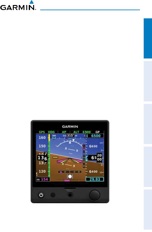
The G5 is an electronic instrument display capable of operating as a standalone flight display or a fully integrated backup instrument for G3X systems. It features a bright, sunlight readable, 3.5-inch color display which is sized to fit in a standard 3-1/8-inch instrument cutout.
When installed as part of a G3X system, the G5 provides a redundant source of attitude and air data to the G3X displays, and additionally provides backup autopilot control allowing coupled GPS approaches to be flown or continued in the event of primary flight display is unavailability. The G5 additionally provides backup autopilot control allowing coupled GPS approaches to be flown or continued in the event of primary flight display loss. In the case of aircraft power loss, the optional battery backup sustains the G5 flight display with up to 4 hours of emergency power.
1.1 BEZEL OVERVIEW
|
|
|
|
|
|
|
|
|
|
|
|
|
|
|
|
|
|
|
|
|
Power/ |
Ambient microSD™ |
Knob |
||||
Backlight |
Light Card Slot |
|
|
|||
|
|
Sensor |
|
|
||
|
|
Figure 1-1 G5 Bezel Overview |
|
|
||
Instruments Flight Overview System
AFCS
Features Additional
Index
190-02072-00 Rev. G |
G5 Electronic Flight Instrument Pilot's Guide for Non-Certified Aircraft |
5 |
Flight Instruments System Overview
AFCS
Additional Features
Index
System Overview
Power |
|
Press to turn unit ON. Press and hold for 5 seconds to |
Button |
|
turn unit OFF. Once on, press to adjust the backlight. |
microSD™ |
|
Insert microSD card to update software and log data. |
Card Slot |
|
|
|
|
|
|
|
Press to access the Menu. |
|
Press |
From the Menu, press to select the desired menu item. |
|
|
Press to accept the displayed value when editing numeric |
|
|
data or selecting from a list. |
|
|
From the Main Menu, turn the Knob to move the cursor |
Knob |
|
to the desired menu item. |
|
From the PFD Page, rotate to adjust the barometric |
|
|
|
|
|
Turn |
setting. |
|
|
From the HSI Page, rotate to adjust the heading or track |
|
|
bug. |
|
|
Turn to select the desired value when editing numeric |
|
|
data or selecting from a list. |
1.2 micro-SD™ CARDS
The G5 data card slot uses micro Secure Digital (SD) cards. The microSD™ card can be used for software updates and data logging. The maximum supported card size is 32GB.
Installing an microSD™ Card:
1)Insert the microSD™ card in the microSD™ card slot with the card contacts facing down (the card should be flush with the face of the bezel).
2)To eject the card, gently press on the microSD™ card to release the spring latch.
1.3SYSTEM POWER-UP
During system initialization, the G5 displays the message ‘ALIGNING’ over the attitude indicator. The G5 should display valid attitude typically within the first minute of power-up. The G5 can align itself both while taxiing and during level flight.
6 |
G5 Electronic Flight Instrument Pilot's Guide for Non-Certified Aircraft |
190-02072-00 Rev. G |
System Overview
1.4 OPERATION
NOTE: Refer to the Installation portion of this manual for information on configuring the G5.
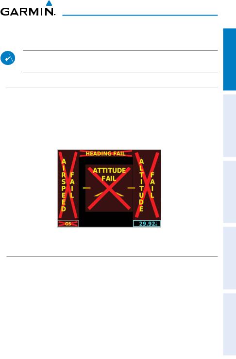
1.4.1 G5 ANNUNCIATIONS
When a G5 function fails, a Red-X is typically displayed over the instrument(s) or data experiencing the failure. Upon G5 power-up, certain instruments remain invalid as equipment begins to initialize. All instruments should be operational within one minute of power-up. If any instrument remains flagged, and it is not likely an installation related problem, the G5 should be serviced by a Garmin-authorized repair facility .
Figure 1-2 G5 Failure Annunciations
1.4.2 G5 ATTITUDE
The G5 calculates aircraft attitude using information from its built-in inertial sensors. Any failure of the inertial sensors results in loss of attitude and information (indicated by Red-X flags over the PFD attitude display). If the G5 senses that the attitude solution is valid, but not yet within the internal accuracy limits, "ALIGNING" is displayed. The G5 can align itself both while taxiing and during level flight.
The G5 will also use GPS and airspeed data to provide the most accurate attitude information. If none of these additional sources of information are available, attitude calculations will still be valid but accuracy may be slightly affected.
Instruments Flight Overview System
AFCS
Features Additional
Index
190-02072-00 Rev. G |
G5 Electronic Flight Instrument Pilot's Guide for Non-Certified Aircraft |
7 |

Flight Instruments System Overview
AFCS
Additional Features
Index
System Overview
1.4.3 G5 HEADING
Magnetic heading is available in a standalone installation with a magnetometer, and when the G5 is configured as a backup in a G3X/G3X Touch system and the G5 is receiving magnetic heading data from an ADAHRS unit. If magnetic heading input data is not available, the G5 will display GPS-derived ground track instead.
The G5 corrects for shifts and variations in the Earth’s magnetic field by applying the Magnetic Field Variation Database. The Magnetic Field Variation Database is derived from the International Geomagnetic Reference Field (IGRF).The IGRF is a mathematical model that describes the Earth’s main magnetic field and its annual rate of change. The database is updated approximately every 5 years via a software update. Failure to update this database could lead to erroneous heading information being displayed to the pilot.
If the G5 senses that the magnetic heading measurement is valid, but possibly outside of the internal accuracy limits, the numeric heading is displayed in yellow.
1.4.4 BACKLIGHT INTENSITY
When set to Auto, the backlight is automatically adjusted according to ambient light conditions. When set to Manual, the backlight level is set by the pilot.
Adjusting backlight intensity:
1)While the unit is turned on, press the Power Button.
2)Turn the Knob to adjust the backlight intensity.
3)Press the Knob to close the backlight page.
Setting the backlight intensity to automatic:
1)While the unit is turned on, press the Power Button.
2)Press the Power Button again to select Auto.
3)Press the Knob to close the backlight page.
8 |
G5 Electronic Flight Instrument Pilot's Guide for Non-Certified Aircraft |
190-02072-00 Rev. G |
System Overview
1.5ACCESSING FUNCTIONALITY
1.5.1PAGES
NOTE: The G5 will automatically return to the PFD Page when the aircraft enters an unusual attitude (if enabled in the system configuration). Refer to the Installation Manual section for more information.
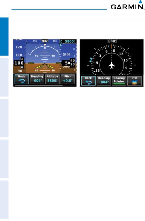
The G5 has two main pages, the HSI Page and the PFD Page. The HSI Page can be accessed from the PFD Page (unless it has been disabled in configuration).
Figure 1-3 PFD Page |
Figure 1-4 HSI Page |
Displaying the HSI page from the PFD page:
1)From the PFD Page press the Knob to display the Menu.
2)Use the Knob to select HSI.
NOTE: The G5 can be configured to power-up on either the PFD or HSI page (if allowed by the current system configuration). Refer to the Installation Manual section for more information.
Instruments Flight Overview System
AFCS
Features Additional
Index
190-02072-00 Rev. G |
G5 Electronic Flight Instrument Pilot's Guide for Non-Certified Aircraft |
9 |
Flight Instruments System Overview
AFCS
Additional Features
Index
System Overview
1.5.2 MENU
Press the Knob to access the G5 Menu. Navigate the menu by rotating the Knob and make selections by pressing the Knob.
Figure 1-5 PFD Page Menu |
Figure 1-6 HSI Page Menu |
10 |
G5 Electronic Flight Instrument Pilot's Guide for Non-Certified Aircraft |
190-02072-00 Rev. G |

Flight Instruments
Section 2 FLIGHT INSTRUMENTS
2.1 PFD PAGE
The G5 PFD Page displays a horizon, airspeed, attitude, altitude, vertical speed, heading, and course deviation information. The following flight instruments and supplemental flight data are displayed on the PFD Page.
22 |
21 |
20 |
19 |
18 |
17 |
|
|
|
|
|
16 |
1 |
|
|
|
|
|
2 |
|
|
|
|
15 |
|
|
|
|
|
|
3 |
|
|
|
|
14 |
4 |
|
|
|
|
13 |
|
|
|
|
|
|
5 |
|
|
|
|
|
|
|
|
|
|
12 |
6 |
|
|
|
|
11 |
|
|
|
|
10 |
|
7 |
|
|
|
|
|
|
|
|
|
|
|
8 |
|
|
|
|
9 |
Figure 2-1 G5 PFD Flight Instruments
Instruments Flight Overview System
AFCS
Features Additional
Index
190-02072-00 Rev. G |
G5 Electronic Flight Instrument Pilot's Guide for Non-Certified Aircraft |
11 |
Flight Instruments
Flight Instruments System Overview
AFCS
Additional Features
Index
1 |
Airspeed Indicator |
12 |
Vertical Speed Indicator |
|
2 |
Attitude Indicator |
13 |
Current Altitude |
|
3 |
Pitch Scale |
14 |
VNAV Indicator or Vertical |
|
4 |
Current Airspeed |
|
Deviation Indicator |
|
15 |
Altimeter |
|||
5 |
Aircraft Symbol |
|||
16 |
Selected Altitude |
|||
6 |
Course Deviation Indicator |
|||
17 |
Navigation Course |
|||
7 |
Slip/Skid Indicator |
|||
18 |
Current Heading or Ground Track |
|||
8 |
Ground Speed (GS) |
|||
19 |
Ground Track |
|||
9 |
Turn Rate Indicator |
|||
20 |
Heading or Ground Track |
|||
10 |
Altimeter Barometric Setting |
|||
21 |
Vspeed Reference |
|||
11 |
Selected Altitude Bug |
|||
22 |
Battery Status Indicator |
|||
|
|
2.1.1 AIRSPEED INDICATOR
NOTE: The G5 Vspeed Reference values depend upon the aircraft’s specific system configuration and may vary from the examples discussed in this section.
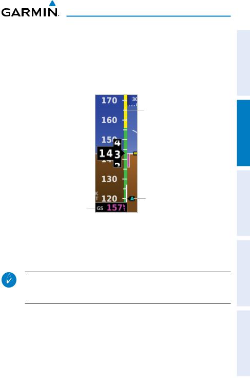
The Airspeed Indicator displays airspeed on a rolling number gauge using a moving tape. The numeric labels and major tick marks on the moving tape are marked at intervals of 10 knots. Speed indication starts at 30 knots, with 60 knots of airspeed viewable at any time. The actual airspeed is displayed inside the black pointer. The pointer remains black until reaching never-exceed speed (VNE), at which point it turns red.
A color-coded (red, white, green, yellow, and red/white “barber pole”) speed range strip is located on the moving tape. The colors denote flaps operating range, normal operating range, caution range, and never-exceed speed (VNE). A red range is also present for low speed awareness.
12 |
G5 Electronic Flight Instrument Pilot's Guide for Non-Certified Aircraft |
190-02072-00 Rev. G |
Flight Instruments
The Airspeed Trend Vector is a vertical, magenta line, extending up or down on the airspeed scale, shown to the right of the color-coded speed range strip. The end of the trend vector corresponds to the predicted airspeed in 6 seconds if the current rate of acceleration is maintained. If the trend vector crosses VNE, the text of the actual airspeed readout changes to yellow. The trend vector is absent if the speed remains constant or if any data needed to calculate airspeed is not available due to a system failure.
|
|
|
|
|
|
|
|
|
|
|
|
|
|
Airspeed Color Ranges |
|
|
|
|
|
|
|
||
|
|
|
|
|
|
|
|
|
|
|
|
|
|
|
|
Actual Airspeed |
|
|
|
|
|
|
|
|
|
|
|
Airspeed Trend Vector |
|
||
|
|
|
|
|
|
||
Vspeed References
Ground Speed
Figure 2-2 Airspeed Indicator
2.1.1.1 VNE ADJUSTED FOR TRUE AIRSPEED OR MACH
NUMBER (OPTIONAL)
NOTE: Mach number data is only available when the G5 is installed as part of a G3X/G3X Touch system and is receiving air temperature data from an ADAHRS.
The airspeed indicator can optionally be configured to display VNE adjusted for true airspeed or maximum Mach number (MMO). This is useful in aircraft where true airspeed or Mach number must be kept below a certain limit. If configured, the G5 can display VNE based on TAS or Mach in addition to IAS, which will cause the displayed value for VNE to be reduced at high altitudes. A solid red band is used between the TAS or Mach limit and the actual indicated value for VNE.
Instruments Flight Overview System
AFCS
Features Additional
Index
190-02072-00 Rev. G |
G5 Electronic Flight Instrument Pilot's Guide for Non-Certified Aircraft |
13 |
Flight Instruments System Overview
AFCS
Additional Features
Index
Flight Instruments
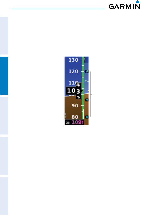
2.1.1.2 VSPEED REFERENCE
Vspeed references including VNE,Vno,Vso,Vs1,Vfe,Va,Vx,Vy,VYse,Vg,Vr, can be configured to display on the G5, refer to the Installation Manual section for more information.
When airspeed is present, the Vspeeds configured are displayed at their respective locations to the right of the airspeed scale, otherwise the Vspeeds are displayed at the bottom of the airspeed indicator.
Vspeed References
Figure 2-3 Vspeed References
14 |
G5 Electronic Flight Instrument Pilot's Guide for Non-Certified Aircraft |
190-02072-00 Rev. G |
Flight Instruments
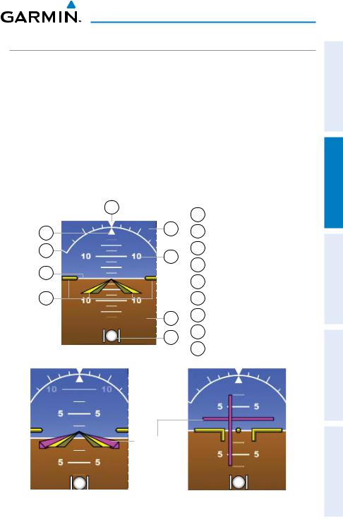
2.1.2 ATTITUDE INDICATOR
Attitude information is displayed over a virtual blue sky and brown ground with a white horizon line. The Attitude Indicator displays the pitch (indicated by the yellow symbolic aircraft on the pitch scale), roll, and slip/skid information.
The horizon line is part of the pitch scale. Pitch markings occur at 2.5˚ intervals through all pitch ranges. Refer to the Installation Manual section to configure the pitch scale.
The inverted white triangle indicates zero on the roll scale. Major tick marks at 30˚ and 60˚ and minor tick marks at 10˚, 20˚, and 45˚ are shown to the left and right of the zero. Angle of bank is indicated by the position of the pointer on the roll scale.
Slip/skid is indicated by the location of the ball.
|
9 |
1 |
Roll Pointer |
|
|
||
1 |
8 |
2 |
Roll Scale |
2 |
7 |
3 |
Horizon Line |
|
4 |
Aircraft Symbol |
|
3 |
|
||
|
5 |
Slip/Skid Indicator |
|
|
|
||
4 |
|
6 |
Land Representation |
|
6 |
7 |
Pitch Scale |
|
5 |
8 |
Sky Representation |
|
|
|
|
|
Figure 2-4 Attitude Indicator |
9 |
Roll Scale Zero |
|
|
|
Flight Director
Figure 2-5 Attitude Indicator with |
Figure 2-6 Attitude Indicator with |
Flight Director (Single Cue) |
Flight Director (Dual Cue) |
Instruments Flight Overview System
AFCS
Features Additional
Index
190-02072-00 Rev. G |
G5 Electronic Flight Instrument Pilot's Guide for Non-Certified Aircraft |
15 |
Flight Instruments System Overview
AFCS
Additional Features
Index
Flight Instruments
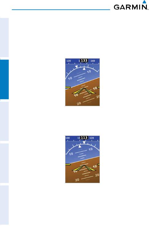
2.1.2.1 ATTITUDE CONFIGURATION
The roll (bank angle) indication may be configured to be a Ground Pointer (default) or a Sky Pointer. Refer to the G5 Installation Manual for configuration information.
The Ground Pointer configuration displays both the roll arc and the pitch ladder anchored to the horizon and the roll pointer beneath the roll arc pointing to the present roll angle.
Figure 2-7 Ground Pointer Configuration
The Sky Pointer configuration displays the pitch ladder moving with the horizon, but the roll arc remains fixed and centered in the display. The roll pointer beneath the roll arc moves with the horizon and in the opposite direction of aircraft roll.
Figure 2-8 Sky Pointer Configuration
16 |
G5 Electronic Flight Instrument Pilot's Guide for Non-Certified Aircraft |
190-02072-00 Rev. G |
Flight Instruments
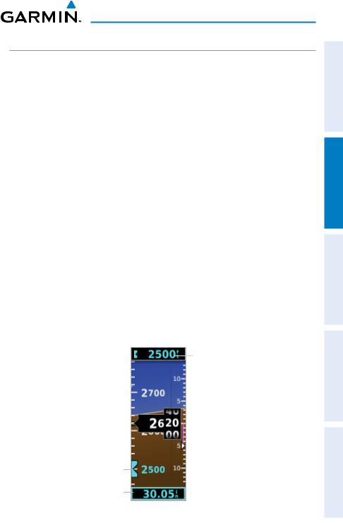
2.1.3 ALTIMETER
The Altimeter displays 400 feet of barometric altitude values at a time on a rolling number gauge using a moving tape. Numeric labels and major tick marks are shown at intervals of 100 feet. Minor tick marks are at intervals of 20 feet. The current altitude is displayed in the black pointer.
The Selected Altitude is displayed above the Altimeter in the box indicated by a selection bug symbol. A bug corresponding to this altitude is shown on the tape; if the Selected Altitude exceeds the range shown on the tape, the bug appears at the corresponding edge of the tape.
The Selected Altitude is synchronized between the G5 and the other displays in a G3X/G3X Touch system.
Setting the selected altitude:
Rotate the ALT SEL Knob on the GMC 307.
Or
1)Press the Knob to display the Menu.
2)Select Altitude and use the Knob to change the Selected Altitude.
Syncing to the current altitude:
Press the ALT SEL Knob on the GMC 307.
Or
1)Press the Knob to display the Menu.
2)Select Altitude and press and hold the Knob to sync the Selected Altitude to the current altitude
Selected
Altitude
Selected
Altitude Bug
Barometric
Setting
Figure 2-9 Altimeter
Instruments Flight Overview System
AFCS
Features Additional
Index
190-02072-00 Rev. G |
G5 Electronic Flight Instrument Pilot's Guide for Non-Certified Aircraft |
17 |
Loading...