


GDL™ 30A XM Weather Data Receiver Installation Instructions
To obtain the best possible performance, install the GDL 30A Weather Data Receiver according to the following instructions. If you experience difficulty during the installation, contact Garmin Product Support or seek the advice of a professional installer.
Product Registration
Help us better support you by completing our online registration today! Connect to our Web site at http://my.garmin.com. Keep the original sales receipt, or a photocopy, in a safe place.
Contact Garmin
Contact Garmin if you have any questions while using your GDL30A. In the USAcontact Garmin Product Support by phone:
(913) 397-8200 or (800) 800-1020, or go to www.garmin.com/support/.
In Europe, contact Garmin (Europe) Ltd. at +44 (0) 870.8501241 (outside the UK) or 0808 2380000 (within the UK).
WARNING: See the Important Safety and Product Information guide in the product box for product warnings and other important information.
Important Numbers
For future reference, write down the important numbers associated with your GDL 30A. The serial number is located on the bottom of the unit.
Serial number
Unique ID numbers are associated with your GDL30A. XM Satellite Radio™ uses these ID numbers to activate and deactivate your XM weather and XM audio.To locate the ID numbers on a GPSMAP® 3000 Series chartplotter, refer to the Main Menu section of the GDL 30AOwner’s Manual.To locate the ID numbers on a GPSMAP4000 or 5000 Series chartplotter, select Configure > System > System Information.
XM WX Weather™ ID
XM Radio ID
Packing List, Accessories, and Tools Needed
Before installing your unit, check that your package includes the following items. If any parts are missing, contact your Garmin dealer immediately.
Standard Package
•GDL 30A unit
•7-pin power cable
•Garmin Marine Network cable—6 ft. (1.8 m)
•Documentation
•Audio cable
•Grommet
•GA 32 Antenna
◦Surface-mount bracket
◦Pole-mount bracket
◦Under-deck mount bracket
◦Mounting hardware (screws and adhesive pads)
Optional Accessories
•GMS 10 network port expander
•Garmin Marine Network cables (20 ft. and 40 ft.)
Tools Needed (Not Included)
•Drill and drill bits
•Fasteners (to mount the GDL 30A)
•Hole saw, 1 in. (surface-mount cable hole)
•Screwdriver (surface-mount screws)
•Center punch and hammer (to mark surface-mount pilot holes)
•Countersink bit (when mounting on fiberglass)
•Marine sealant (for certain mounting options)
May 2008 |
190-00930-02 Rev. B |
Printed in Taiwan |

Unit Overview
LED status indicator
Power/data connector
Network port
Weather cap
Antenna connector |
Audio connector |
Mounting holes |
Caution: Always wear safety goggles, ear protection, and a dust mask when drilling, cutting, or sanding.When drilling or cutting, always check what is on the opposite side of the surface.
Mounting the GDL 30A
Mount the GDL 30A in a location that is dry and well ventilated. Avoid mounting the unit where it may become submerged or exposed to extreme temperatures above 158°F or below 5°F (above 70°C or below -15°C). Verify there is enough clearance to attach the cables to the unit.
Make sure the Status LED is visible to view the blink codes.
To mount the GDL 30A:
1.Using the unit as a template, mark the location of the mounting holes. If needed, additional holes can be drilled in the side mounting flanges.
2.Secure the GDL 30A using fasteners appropriate for the mounting surface.
Connecting the Power Cable
The power cable can be connected directly to the boat battery or through an open connector on the fuse block.
To connect the power cable to a battery:
1.Connect the red wire to the positive (+) terminal of the battery. Do not remove the AGC/3AG 2.0 amp fuse holder from the red wire.
2.Connect the black wire to the negative (-) terminal of the battery.
3.Connect the power cable to the GDL 30A 7-pin connector labeled POWER.
2 A fuse |
10–35 VDC
Connecting to a Battery
Red
To GDL 30A
Black
Battery + Battery -
To connect the power cable to a fuse block: |
Connecting to a Fuse Block |
||
1. |
Remove the AGC/3AG 2.0 A fuse holder from the red wire. |
||
|
|||
2. |
Connect the red wire to an open fuse holder in the fuse block. Make sure that the red wire is connected to the positive side of the fuse block. |
||
3. |
Connect the black wire to the negative side of the fuse block. |
|
|
4. |
Install a 2.0 A fuse in the fuse holder. |
|
|
5. |
Connect the power cable to the GDL 30A 7-pin connector labeled POWER. |
|
|
|
GDL 30A Installation Instructions |
Connecting the GDL 30A to a Chartplotter
Connect the GDL30Ato a chartplotter by using the Garmin Marine Network Cable (included). See the installation instructions for your chartplotter for more detailed information on setting up a Garmin Marine Network.
Connecting to a GPSMAP 4000/5000 series chartplotter:
•A GPSMAP 4000/5000 series chartplotter has three network connectors available. Connect the GDL 30A to any of these connectors.
•If you have multiple chartplotters, connect the GDL 30A to an open connector on any one of the chartplotters.
Connecting to a GPSMAP 3000 series chartplotter:
•A GPSMAP 3000 series chartplotter has one network connector available. If you do not have any other Garmin Marine Network devices, connect the GDL 30A directly to the GPSMAP 3000 series chartplotter.
•If you need to connect the GDL 30A to multiple GPSMAP 3000 series chartplotters, a GMS 10 Network Port Expander is required.
Garmin does not recommend cutting the Marine Network cable, though cutting the cable may be necessary in certain circumstances. Refer to the installation instructions for your chartplotter if you need to cut the Marine Network cable.
If you need to drill a hole in your boat, use the included grommet that is specifically designed to cover holes drilled for the Garmin Marine Network Cable. If a longer cable is needed, contact Garmin or your Garmin dealer.To ensure safety, use tie-wraps, fasteners, and sealant to secure the cable along a route and through any bulkhead or deck.
Connecting the Audio Cable
Connect the audio cable (included) to the GDL 30A AUDIO connector and to the audio inputs on your stereo receiver.
Mounting the GA 32 Antenna
You can surface mount the GA 32 antenna, attach it to a standard 1 in. OD pipe-threaded-pole marine mount (14 threads-per-inch—not included), or install the antenna under fiberglass.
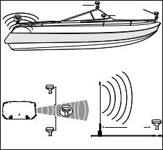
Select a suitable location for the GA32 antenna on your boat.To ensure the best reception, mount the GA 32 antenna in a location that has a clear, unobstructed view of the sky in all directions.
•Avoid mounting the GA 32 antenna where it is shaded by the superstructure of the boat, a radome antenna, or mast.
• Mount the GA32 antenna at least 3 ft. (1 m) away from (preferably above) the path of any radar beam or a VHFradio antenna.
•Do not cut orshorten the antenna cable. The length of the antenna cable is set to provide optimal performance. Shortening the cable adversely effects the performance of the GA32.
•If additional antenna cable is needed, Garmin recommends a 50-foot cable from Delphi, part number SA10006.The following adapters are required: BNC plug to SMB jack – available from Newark, part number 92C7329 and BNC jack to SMB plug – available from Newark, part number 92C7330.
Temporarily secure the antenna in the preferred mounting location and test it for correct operation. If you experience interference from other electronics, try a different location. When you verify correct operation, permanently mount the antenna.
Surface mounting the GA 32 Antenna
1.Use the surface-mount bracket as your mounting template.
•Use a center punch to mark the three screw locations on the surface.
•Use a pencil to trace the cable hole in the center of the bracket.
•Set the surface-mount bracket aside. Do not drill through the surface-mount bracket.
|
Better |
Best |
|
|
|
Good |
|
|
|
SSBARNETT |
|
EMI |
|
|
|
EMI (Electromagnetic Interference) |
|||
from engine components |
|||
Above - best |
3 ft. (1 m) |
|
|
|
|
||
Below - OK |
3 ft. (1 m) |
3 ft. |
|
(1 m) |
|||
|
|||
Radar |
|
VHF Radio Antenna |
|
GA 32 Antenna Placement Considerations
GDL 30A Installation Instructions
 Loading...