


 Loading...
G1000H |
™ |
Integrated Flight Deck |
|
||
|
Pilot’s Guide |
Bell 407GX

Copyright © 2011 Garmin Ltd. or its subsidiaries. All rights reserved.
This manual reflects the operation of System Software version 1237.03 or later for the Bell 407GX Helicopter. Some differences in operation may be observed when comparing the information in this manual to earlier or later software versions.
Garmin International, Inc., 1200 East 151st Street, Olathe, Kansas 66062, U.S.A.
Tel: 913/397.8200 |
Fax: 913/397.8282 |
Garmin AT, Inc., 2345 Turner Road SE, Salem, OR 97302, U.S.A. |
|
Tel: 503/391.3411 |
Fax 503/364.2138 |
Garmin (Europe) Ltd, Liberty House, Bulls Copse Road, Hounsdown Business Park, Southampton, SO40 9RB, U.K. |
|
Tel: 44/0870.8501241 |
Fax: 44/0870.8501251 |
Garmin Corporation, No. 68, Jangshu 2nd Road, Shijr, Taipei County, Taiwan |
|
Tel: 886/02.2642.9199 |
Fax: 886/02.2642.9099 |
For after-hours emergency, aircraft on ground (AOG) technical support for Garmin panel mount and integrated avionics systems, please contact Garmin’s AOG Hotline at 913.397.0836.
Web Site Address: www.garmin.com
Except as expressly provided herein, no part of this manual may be reproduced, copied, transmitted, disseminated, downloaded or stored in any storage medium, for any purpose without the express written permission of Garmin. Garmin hereby grants permission to download a single copy of this manual and of any revision to this manual onto a hard drive or other electronic storage medium to be viewed for personal use, provided that such electronic or printed copy of this manual or revision must contain the complete text of this copyright notice and provided further that any unauthorized commercial distribution of this manual or any revision hereto is strictly prohibited.
Garmin®, WATCH®, FliteCharts®, and SafeTaxi® are registered trademarks of Garmin Ltd. or its subsidiaries. These trademarks may not be used without the express permission of Garmin.
G1000H™ is a trademark of Garmin Ltd. or its subsidiaries. This trademark may not be used without the express permission of Garmin.
Bendix/King® and Honeywell® are registered trademarks of Honeywell International, Inc.; Becker® is a registered trademark of Becker Flugfunkwerk GmbH; NavData® is a registered trademark of Jeppesen, Inc.; XM® is a registered trademark of XM Satellite Radio, Inc.
AOPA Membership Publications, Inc. and its related organizations (hereinafter collectively “AOPA”) expressly disclaim all warranties, with respect to the AOPA information included in this data, express or implied, including, but not limited to, the implied warranties of merchantability and fitness for a particular purpose. The information is provided “as is” and AOPA does not warrant or make any representations regarding its accuracy, reliability, or otherwise. Under no circumstances including negligence, shall AOPA be liable for any incidental, special or consequential damages that result from the use or inability to use the software or related documentation, even if AOPA or an AOPA authorized representative has been advised of the possibility of such damages. User agrees not to sue AOPA and, to the maximum extent allowed by law, to release and hold harmless AOPA from any causes of action, claims or losses related to any actual or alleged inaccuracies in the information. Some jurisdictions do not allow the limitation or exclusion of implied warranties or liability for incidental or consequential damages so the above limitations or exclusions may not apply to you.
September, 2011 |
190-01255-00 Rev. B |
Printed in the U.S.A. |
190-01255-00 Rev. B |
Garmin G1000H™ Pilot’s Guide for the Bell 407GX |

LIMITED WARRANTY
LIMITED WARRANTY
Within the warranty period, Garmin will, at its sole discretion, repair or replace any components that fail in normal use. Such repairs or replacement will be made at no charge to the customer for parts and/or labor incidental to the direct repair of said product. Garmin may, at its discretion with prior approval, reimburse an authorized Garmin Service Center for associated labor costs incurred for removal and replacement of the panel mount product installed in an aircraft. The customer shall be responsible for any transportation or other cost. This warranty does not apply to: (i) cosmetic damage, such as scratches, nicks and dents; (ii) consumable parts, such as batteries, unless product damage has occurred due to a defect in materials or workmanship; (iii) damage caused by accident, abuse, misuse, water, flood, fire, or other acts of nature or external causes; (iv) damage caused by service performed by anyone who is not an authorized service provider of Garmin; or (v) damage to a product that has been modified or altered without the written permission of Garmin. In addition, Garmin reserves the right to refuse warranty claims against products or services that are obtained and/or used in contravention of the laws of any country.
THE WARRANTIES AND REMEDIES CONTAINED HEREIN ARE EXCLUSIVE AND IN LIEU OF ALL OTHER WARRANTIES, WHETHER EXPRESS, IMPLIED OR STATUTORY, INCLUDING ANY LIABILITY ARISING UNDER ANY WARRANTY OF MERCHANTABILITY OR FITNESS FOR A PARTICULAR PURPOSE, STATUTORY OR OTHERWISE. THIS WARRANTY GIVES YOU SPECIFIC LEGAL RIGHTS, WHICH MAY VARY FROM STATE TO STATE.
IN NO EVENT SHALL GARMIN BE LIABLE FOR ANY INCIDENTAL, SPECIAL, INDIRECT OR CONSEQUENTIAL DAMAGES, WHETHER RESULTING FROM THE USE, MISUSE, OR INABILITY TO USE THIS PRODUCT OR FROM DEFECTS IN THE PRODUCT. Some states do not allow the exclusion of incidental or consequential damages, so the above limitations may not apply in every case.
Garmin retains the exclusive right to repair or replace (with a new or newly-overhauled replacement product) the product or offer a full refund of the purchase price at its sole discretion. SUCH REMEDY SHALL BE YOUR SOLE AND EXCLUSIVE REMEDY FOR ANY BREACH OF WARRANTY.
To obtain warranty service, contact your local Garmin Authorized Service Center. For assistance in locating the nearest Service Center, call Garmin Customer Service at one of the numbers listed below.
Products sold through online auctions are not eligible for warranty coverage or rebates or other special offers from Garmin. Online auction confirmations are not accepted for warranty verification.To obtain warranty service, an original or copy of the sales receipt from the original retailer is required. Garmin will not replace missing components from any package purchased through an online auction.
Garmin International Inc. |
|
Garmin (Europe) Ltd. |
|
|
1200 East 151st Street, Olathe, Kansas 66062 |
Liberty House, Bulls Copse Road, Southampton, SO40 |
|||
Telephone: |
(913)397-8200 |
9RB, UK |
|
|
Telephone Toll Free: |
(888)606-5482 |
Telephone: |
++44 (0) |
870-8501243 |
Facsimile: |
(913)397-8282 |
Telephone Toll Free: |
++44 (0) |
0808 238 0000 |
Facsimile Toll Free: |
(800)801-4670 |
(option 5) |
|
|
E-mail: orders@garmin.com |
Facsimile: |
++44 (0) |
238052004 |
|
avionics@garmin.com |
E-mail: avionics.europe@garmin.com |
|||
warranty@garmin.com |
|
|
|
|
ii |
Garmin G1000H™ Pilot’s Guide for the Bell 407GX |
190-01255-00 Rev. B |

WARNINGS, CAUTIONS, AND NOTES
WARNING: Navigation and terrain separation must NOT be predicated upon the use of the terrain avoidance feature. The terrain avoidance feature is NOT intended to be used as a primary reference for terrain avoidance and does not relieve the pilot from the responsibility of being aware of surroundings during flight. The terrain avoidance feature is only to be used as an aid for terrain avoidance. Terrain data is obtained from third party sources. Garmin is not able to independently verify the accuracy of the terrain data.
WARNING: The displayed minimum safe altitudes (MSAs) are only advisory in nature and should not be relied upon as the sole source of obstacle and terrain avoidance information. Always refer to current aeronautical charts for appropriate minimum clearance altitudes.
WARNING: The altitude calculated by the GPS receivers is geometric height above Mean Sea Level and could vary significantly from the altitude displayed by pressure altimeters, such as the GDC 74B Air Data Computer, or other altimeters in aircraft. GPS altitude should never be used for vertical navigation. Always use pressure altitude displayed by the PFD or other pressure altimeters in aircraft.
WARNING: Do not use outdated database information. Databases used in the system must be updated regularly in order to ensure that the information remains current. Pilots using any outdated database do so entirely at their own risk.
WARNING: Do not use basemap (land and water data) information for primary navigation. Basemap data is intended only to supplement other approved navigation data sources and should be considered as an aid to enhance situational awareness.
 WARNING: Traffic information shown on system displays is provided as an aid in visually acquiring traffic.
WARNING: Do not use datalink weather products (e.g., XM WX Satellite Weather, GFDS World Wide Weather, or FIS-B) for hazardous weather penetration. Weather information provided by these products is aged by up to several minutes and may not depict actual weather conditions as they currently appear.
WARNING: NEXRAD weather data is to be used for long-range planning purposes only. Due to inherent delays in data transmission and the relative age of the data, NEXRAD weather data should not be used for short-range weather avoidance.
WARNING: The Garmin G1000H, as installed in the Bell 407GX helicopter, has a very high degree of functional integrity. However, the pilot must recognize that providing monitoring and/or self-test capability for all conceivable system failures is not practical. Although unlikely, it may be possible for erroneous operation to occur without a fault indication shown by the system. It is thus the responsibility of the pilot to detect such an occurrence by means of cross-checking with all redundant or correlated information available in the cockpit.
 WARNING: For safety reasons, system operational procedures must be learned on the ground.
190-01255-00 Rev. B |
Garmin G1000H™ Pilot’s Guide for the Bell 407GX |
iii |

WARNINGS, CAUTIONS, AND NOTES
WARNING: The United States government operates the Global Positioning System and is solely responsible for its accuracy and maintenance. The GPS system is subject to changes which could affect the accuracy and performance of all GPS equipment. Portions of the system utilize GPS as a precision electronic NAVigation AID (NAVAID). Therefore, as with all NAVAIDs, information presented by the system can be misused or misinterpreted and, therefore, become unsafe.
WARNING: To reduce the risk of unsafe operation, carefully review and understand all aspects of the G1000H Pilot’s Guide documentation and the Bell 407GX Rotorcraft Flight Manual. Thoroughly practice basic operation prior to actual use. During flight operations, carefully compare indications from the system to all available navigation sources, including the information from other NAVAIDs, visual sightings, charts, etc. For safety purposes, always resolve any discrepancies before continuing navigation.
WARNING: The illustrations in this guide are only examples. Never use the system to attempt to penetrate a thunderstorm. Both the FAA Advisory Circular, Subject: Thunderstorms, and the Aeronautical Information Manual (AIM) recommend avoiding “by at least 20 miles any thunderstorm identified as severe or giving an intense radar echo.”
WARNING: Lamp(s) inside this product may contain mercury (HG) and must be recycled or disposed of according to local, state, or federal laws. For more information, refer to our website at www.garmin.com/ aboutGarmin/environment/disposal.jsp.
WARNING: Because of variation in the earth’s magnetic field, operating the system within the following areas could result in loss of reliable attitude and heading indications. North of 72° North latitude at all longitudes. South of 70° South latitude at all longitudes. North of 65° North latitude between longitude 75° W and 120° W. (Northern Canada). North of 70° North latitude between longitude 70° W and 128° W. (Northern Canada). North of 70° North latitude between longitude 85° E and 114° E. (Northern Russia). South of 55° South latitude between longitude 120° E and 165° E. (Region south of Australia and New Zealand).
WARNING: Do not use GPS to navigate to any active waypoint identified as a ‘NON WGS84 WPT’ by a system message. ‘NON WGS84 WPT’ waypoints are derived from an unknown map reference datum that may be incompatible with the map reference datum used by GPS (known as WGS84) and may be positioned in error as displayed.
CAUTION: The PFD and MFD displays use a lens coated with a special anti-reflective coating that is very sensitive to skin oils, waxes, and abrasive cleaners. CLEANERS CONTAINING AMMONIA WILL HARM THE ANTI-REFLECTIVE COATING. It is very important to clean the lens using a clean, lint-free cloth and an eyeglass lens cleaner that is specified as safe for anti-reflective coatings.
CAUTION: The system does not contain any user-serviceable parts. Repairs should only be made by an authorized Garmin service center. Unauthorized repairs or modifications could void both the warranty and the pilot’s authority to operate this device under FAA/FCC regulations.
iv |
Garmin G1000H™ Pilot’s Guide for the Bell 407GX |
190-01255-00 Rev. B |

WARNINGS, CAUTIONS, AND NOTES
NOTE: All visual depictions contained within this document, including screen images of the panel and displays, are subject to change and may not reflect the most current system and databases. Depictions of equipment may differ slightly from the actual equipment.
NOTE:This device complies with part 15 of the FCC Rules. Operation is subject to the following two conditions:
(1) this device may not cause harmful interference, and (2) this device must accept any interference received, including interference that may cause undesired operation.
NOTE: This product, its packaging, and its components contain chemicals known to the State of California to cause cancer, birth defects, or reproductive harm. This notice is being provided in accordance with California’s Proposition 65. If you have any questions or would like additional information, please refer to our web site at www.garmin.com/prop65.
NOTE: Interference from GPS repeaters operating inside nearby hangars can cause an intermittent loss of attitude and heading displays while the aircraft is on the ground. Moving the aircraft more than 100 yards away from the source of the interference should alleviate the condition.
 NOTE: Use of polarized eyewear may cause the flight displays to appear dim or blank.
190-01255-00 Rev. B |
Garmin G1000H™ Pilot’s Guide for the Bell 407GX |
v |

REVISION INFORMATION
|
|
|
Record of Revisions |
|
Part Number |
Revision |
Date |
Page Range |
Description |
190-01255-00 |
A |
February, 2011 |
All |
Initial release |
|
B |
September, 2011 |
All |
Added 3D Audio and Voice Recognition |
|
|
|
|
Various clerical changes |
|
|
|
|
|
vi |
Garmin G1000H™ Pilot’s Guide for the Bell 407GX |
190-01255-00 Rev. B |

TABLE OF CONTENTS
|
SECTION 1 SYSTEM OVERVIEW |
|
1.1 |
System Description.................................................. |
1 |
1.2 |
Line Replaceable Units (LRU).................................. |
2 |
1.3 |
G1000H Controls...................................................... |
6 |
|
PFD Controls................................................................. |
6 |
|
Audio Panel Controls..................................................... |
8 |
1.4 |
Secure Digital Cards.............................................. |
10 |
1.5 |
System Power-up................................................... |
11 |
1.6 |
System Operation.................................................. |
12 |
|
Normal Display Operation............................................ |
12 |
|
Reversionary Display Operation.................................... |
13 |
|
AHRS Operation.......................................................... |
14 |
|
G1000H System Annunciations..................................... |
15 |
|
Softkey Function......................................................... |
16 |
|
GPS Receiver Operation............................................... |
21 |
1.7 |
Accessing G1000H Functionality.......................... |
26 |
|
Menus........................................................................ |
26 |
|
MFD Page Groups....................................................... |
27 |
|
MFD System Pages...................................................... |
31 |
1.8 |
Display Backlighting.............................................. |
44 |
|
Automatic Adjustment................................................. |
44 |
|
Manual Adjustment..................................................... |
44 |
|
SECTION 2 FLIGHT INSTRUMENTS |
|
2.1 |
Flight Instruments.................................................... |
50 |
|
Airspeed Indicator....................................................... |
50 |
|
Attitude Indicator........................................................ |
51 |
|
Altimeter.................................................................... |
52 |
|
Vertical Speed Indicator (VSI)....................................... |
54 |
|
Vertical Deviation........................................................ |
55 |
|
Horizontal Situation Indicator (HSI)............................... |
56 |
|
Course Deviation Indicator (CDI)................................... |
62 |
2.2 |
Supplemental Flight Data..................................... |
69 |
|
Temperature Displays.................................................. |
69 |
|
Wind Data.................................................................. |
70 |
|
Vertical Navigation (VNV) Indications............................ |
71 |
2.3 |
PFD Annunciations and Alerting Functions......... |
72 |
|
System Alerting........................................................... |
72 |
|
Marker Beacon Annunciations...................................... |
72 |
|
Traffic Annunciation..................................................... |
73 |
|
HTAWS Annunciations................................................. |
73 |
|
Altitude Alerting.......................................................... |
74 |
|
Low Altitude Annunciation........................................... |
74 |
|
Minimum Descent Altitude/Decision Height Alerting....... |
75 |
|
Radar Altimeter........................................................... |
76 |
2.4 |
Abnormal Operations............................................ |
78 |
|
Abnormal GPS Conditions............................................ |
78 |
|
Unusual Attitudes........................................................ |
79 |
SECTION 3 ENGINE AND CREW ALERTING SYSTEMS |
||
3.1 |
Engine Indication System (EIS) Strip................... |
83 |
3.2 |
Engine Power and Speed Indications.................. |
85 |
|
Power Situation Indicator............................................. |
85 |
|
Dual Tachometer......................................................... |
86 |
|
Alternate Engine Data Source Annunciations................. |
86 |
3.3 |
Engine Page............................................................ |
87 |
|
Power Assurance Check............................................... |
88 |
3.4 |
Crew Alerting System (CAS)................................. |
89 |
|
CAS Message Prioritization.......................................... |
90 |
|
SECTION 4 AUDIO PANEL AND CNS |
|
4.1 |
Overview................................................................. |
93 |
|
MFD/PFD Controls and Frequency Display...................... |
94 |
|
Audio Panel Controls................................................... |
96 |
4.2 |
COM Operation...................................................... |
98 |
|
COM Transceiver Selection and Activation...................... |
98 |
|
COM Transceiver Manual Tuning................................... |
99 |
|
Quick-Tuning and Activating 121.500 MHz.................. |
100 |
|
Auto-Tuning the COM Frequency................................ |
101 |
|
Frequency Spacing..................................................... |
105 |
|
Automatic Squelch.................................................... |
106 |
|
COM Volume............................................................ |
106 |
4.3 |
NAV Operation..................................................... |
107 |
|
NAV Radio Selection and Activation............................ |
107 |
|
NAV Receiver Manual Tuning...................................... |
108 |
|
Auto-Tuning a NAV Frequency from the MFD............... |
110 |
|
Marker Beacon Receiver (Optional)............................. |
115 |
|
DME Tuning (Optional)............................................... |
116 |
4.4 |
GTX 33 Mode S Transponder.............................. |
117 |
|
Transponder Controls................................................. |
117 |
|
Transponder Mode Selection...................................... |
118 |
|
Entering a Transponder Code...................................... |
121 |
|
IDENT Function......................................................... |
122 |
4.5 |
Additional Audio Panel Functions...................... |
123 |
|
Power-Up................................................................. |
123 |
190-01255-00 Rev. B |
Garmin G1000H™ Pilot’s Guide for the Bell 407GX |
vii |

TABLE OF CONTENTS
|
Mono/Stereo Headsets............................................... |
123 |
|
Intercom................................................................... |
123 |
|
Clearance Recorder and Player (Optional).................... |
129 |
|
Split COM................................................................. |
130 |
|
3D Audio.................................................................. |
131 |
|
Voice Recognition..................................................... |
133 |
|
Entertainment Inputs................................................. |
136 |
4.6 Audio Panel Preflight Procedure........................ |
137 |
|
4.7 |
Abnormal Operation............................................ |
138 |
|
Stuck Microphone..................................................... |
138 |
|
COM Tuning Failure................................................... |
138 |
|
Audio Panel Fail-Safe Operation.................................. |
138 |
|
SECTION 5 FLIGHT MANAGEMENT |
|
5.1 |
Introduction.......................................................... |
139 |
|
Navigation Status Box............................................... |
140 |
5.2 |
Using Map Displays............................................. |
142 |
|
Map Orientation....................................................... |
142 |
|
Map Range............................................................... |
144 |
|
Map Panning............................................................ |
146 |
|
Measuring Bearing and Distance................................ |
151 |
|
Topography.............................................................. |
152 |
|
Map Symbols............................................................ |
155 |
|
Airways.................................................................... |
161 |
|
Track Vector.............................................................. |
163 |
|
Wind Vector.............................................................. |
164 |
|
Nav Range Ring........................................................ |
165 |
|
Fuel Range Ring........................................................ |
166 |
|
Field of View (SVS).................................................... |
167 |
|
Selected Altitude Intercept Arc.................................... |
168 |
5.3 |
Waypoints............................................................. |
169 |
|
Airports.................................................................... |
170 |
|
Intersections............................................................. |
177 |
|
NDBs....................................................................... |
179 |
|
VORs....................................................................... |
181 |
|
User Waypoints......................................................... |
183 |
5.4 |
Airspaces............................................................... |
189 |
5.5 Direct-to-Navigation .......................................... |
193 |
|
5.6 |
Flight Planning..................................................... |
199 |
|
Flight Plan Creation................................................... |
200 |
|
Adding Waypoints to an Existing Flight Plan................ |
205 |
|
Adding Airways to a Flight Plan.................................. |
207 |
|
Adding Procedures to a Stored Flight Plan................... |
209 |
|
Flight Plan Storage.................................................... |
216 |
|
Flight Plan Editing..................................................... |
218 |
|
Along Track Offsets.................................................... |
221 |
|
Parallel Track............................................................. |
223 |
|
Activating a Flight Plan Leg........................................ |
226 |
|
Inverting a Flight Plan................................................ |
227 |
|
Flight Plan Views....................................................... |
228 |
|
Closest Point of FPL................................................... |
230 |
5.7 |
Vertical Navigation.............................................. |
231 |
|
Altitude Constraints.................................................. |
233 |
5.8 |
Procedures............................................................ |
237 |
|
Departures................................................................ |
237 |
|
Arrivals .................................................................... |
240 |
|
Approaches ............................................................. |
242 |
5.9 |
Trip Planning......................................................... |
248 |
|
Trip Planning............................................................. |
248 |
5.10 |
RAIM Prediction................................................... |
252 |
5.11 |
Navigating a Flight Plan..................................... |
255 |
5.12 |
Abnormal Operation............................................ |
283 |
|
SECTION 6 HAZARD AVOIDANCE |
|
6.1 |
XM WX Satellite Weather.................................... |
285 |
|
Activating Services.................................................... |
285 |
|
Using XM WX Satellite Weather Products.................... |
286 |
6.2 |
GFDS Worldwide Weather................................... |
315 |
|
GFDS Weather Data Requests..................................... |
323 |
|
Worldwide Weather Products..................................... |
327 |
|
Abnormal Operations................................................ |
338 |
6.3 |
HTAWS................................................................... |
340 |
|
Displaying HTAWS Data............................................. |
341 |
|
HTAWS Page............................................................. |
342 |
|
HTAWS Alerts............................................................ |
344 |
|
System Status........................................................... |
349 |
6.4 |
Traffic Information Service (TIS)........................ |
351 |
|
Displaying TRAFFIC Data............................................ |
352 |
|
Traffic Map Page....................................................... |
354 |
|
TIS Alerts.................................................................. |
355 |
|
System Status........................................................... |
356 |
6.5 |
Garmin GTS Traffic............................................... |
358 |
|
Theory of operation................................................... |
358 |
|
TAS Alerts................................................................. |
361 |
|
System Test............................................................... |
362 |
|
Operation................................................................. |
363 |
viii |
Garmin G1000H™ Pilot’s Guide for the Bell 407GX |
190-01255-00 Rev. B |
TABLE OF CONTENTS
SECTION 7 AUTOMATIC FLIGHT CONTROL SYSTEM
|
SECTION 8 ADDITIONAL FEATURES |
|
8.1 |
Synthetic Vision System (SVS)............................ |
376 |
|
SVS Operation........................................................... |
377 |
|
SVS Features............................................................. |
379 |
|
Field of View............................................................. |
388 |
8.2 |
SafeTaxi................................................................. |
390 |
8.3 |
ChartView............................................................. |
396 |
|
ChartView Softkeys................................................... |
396 |
|
Terminal Procedures Charts........................................ |
397 |
|
Chart Options........................................................... |
405 |
|
Day/Night View......................................................... |
411 |
|
ChartView Cycle Number and Expiration Date.............. |
413 |
8.4 |
FliteCharts............................................................. |
416 |
|
FliteCharts Softkeys................................................... |
416 |
|
Terminal Procedures Charts........................................ |
417 |
|
Chart Options........................................................... |
424 |
|
Day/Night View......................................................... |
428 |
|
FliteCharts Cycle Number and Expiration Date............. |
430 |
8.5 |
AOPA Airport Directory....................................... |
433 |
|
AOPA Database Cycle Number and Revision................ |
434 |
8.6 |
Satellite Telephone and Data Link Services...... |
436 |
|
Registering With Garmin Flight Data Services............... |
436 |
|
Disable/Enable Iridium Transceiver.............................. |
439 |
|
Telephone Communication......................................... |
440 |
|
Text Messaging (SMS)................................................ |
447 |
|
WI-FI Connections..................................................... |
458 |
|
System Data Logging................................................. |
464 |
8.7 |
XM Radio Entertainment.................................... |
467 |
|
Activating XM Satellite Radio Services........................ |
467 |
|
Using XM Radio........................................................ |
468 |
8.8 |
Scheduler.............................................................. |
472 |
8.9 |
Auxiliary Video..................................................... |
474 |
|
Video Setup.............................................................. |
475 |
|
Display Selection....................................................... |
476 |
|
Input Selection.......................................................... |
477 |
|
Zoom/Range............................................................. |
477 |
8.9 |
Abnormal Operation............................................ |
478 |
|
SVS Troubleshooting.................................................. |
478 |
|
Reversionary Mode.................................................... |
478 |
|
Unusual Attitudes...................................................... |
479 |
APPENDICES |
|
Annunciations and Alerts.............................................. |
483 |
CAS Messages.......................................................... |
483 |
G1000H System Annunciations................................... |
485 |
G1000H System Message Advisories........................... |
490 |
Flight Plan Import/Export Messages............................ |
499 |
Database Management................................................. |
501 |
Jeppesen Databases.................................................. |
501 |
Garmin Databases..................................................... |
505 |
Glossary.......................................................................... |
511 |
Frequently Asked Questions......................................... |
517 |
General TIS Information................................................ |
521 |
Introduction.............................................................. |
521 |
TIS vs. TAS/TCAS........................................................ |
521 |
TIS Limitations.......................................................... |
521 |
Display Symbols............................................................. |
523 |
INDEX |
|
Index ................................................................................ |
I-1 |
190-01255-00 Rev. B |
Garmin G1000H™ Pilot’s Guide for the Bell 407GX |
ix |

TABLE OF CONTENTS
Blank Page
x |
Garmin G1000H™ Pilot’s Guide for the Bell 407GX |
190-01255-00 Rev. B |

SYSTEM OVERVIEW
SECTION 1 SYSTEM OVERVIEW
1.1 SYSTEM DESCRIPTION
This section provides an overview of the G1000H Integrated Flight Deck as installed in the Bell 407GX. The G1000H system is an integrated flight control system that presents flight instrumentation, position, navigation, communication, and identification information to the pilot through large-format displays. The system consists of the following Line Replaceable Units (LRUs):
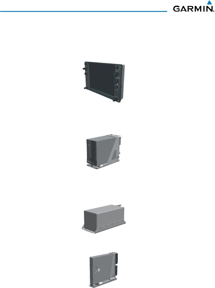
•GDU 1040H Primary Flight Display (PFD) and Multi Function Display (MFD)
•GIA 63H Integrated Avionics Unit
•GDC 74H Air Data Computer (ADC)
•GEA 71H Engine/Airframe Unit
•GSC 46 Signal Conditioner
•GRS 77H Attitude and Heading Reference System (AHRS)
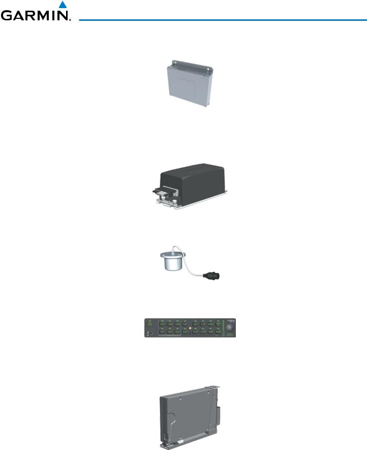
•GMU 44 Magnetometer
•GMA 350H Audio System with Integrated Marker Beacon Receiver
•GTX 33H Mode S Transponder with extended squitter
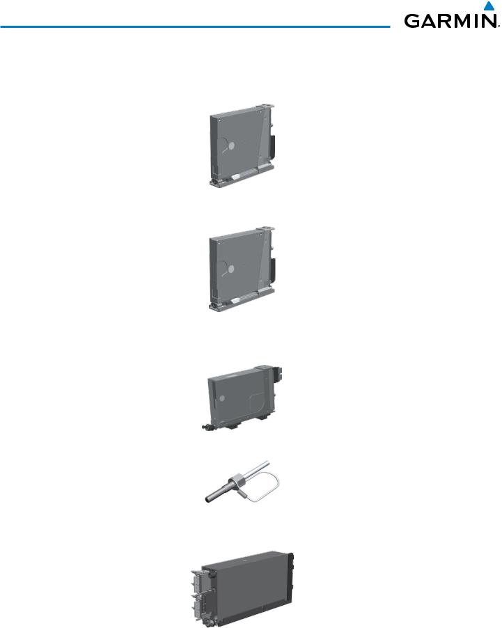
•GDL 69AH Satellite Data Link Receiver (optional)
•GDL 59H Data Link (optional)
•GSR 56H Iridium Transceiver (optional)
•GTS 800 Traffic Avoidance System (optional)
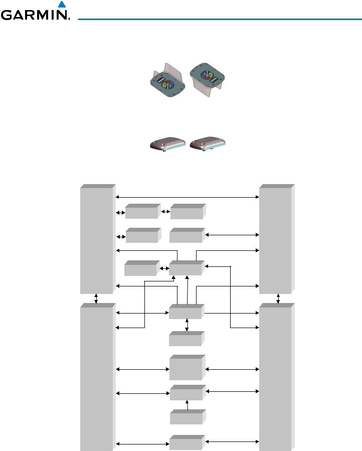
•GA 58 Directional Antenna (optional)
•GTP 59 Outside Air Temperature (OAT) Probe
•GA 36 GPS/WAAS and GA 37 GPS/WAAS/XM Antennas
A top-level G1000H system block diagram is shown in Figure 1-1 (it does not include the GA 36, GA 37 and GA 58.
190-01255-00 Rev. B |
Garmin G1000H™ Pilot’s Guide for the Bell 407GX |
1 |
SYSTEM OVERVIEW
1.2 LINE REPLACEABLE UNITS (LRU)
•GDU 1040H (2) – One unit is configured as a PFD, the other as an MFD, each featuring a 10.4-inch LCD with 1024 x 768 resolution. The unit installed on the right/pilot side is designated as the PFD, and the one installed on the left/copilot side is designated as the MFD. These units communicate with each other and with the onside GIA 63H Integrated Avionics Unit through a High-Speed Data Bus (HSDB) connection.
•GIA 63H (2) – Functions as the main communication hub, linking all LRUs with the on-side PFD. Each GIA 63H contains a GPS SBAS receiver, VHF COM/NAV/GS receivers, a flight director (FD) and system integration microprocessors. Each GIA 63W is paired with a respective GDU 1040H via HSDB connection. The GIA 63Hs are not paired together and do not communicate with each other directly.
•GDC 74H (1) – Processes data from the pitot/static system as well as the OAT probe. This unit provides pressure altitude, airspeed, vertical speed and OAT information to the G1000H system, and it communicates with the each GIA 63H, GDU 1040H and GRS 77H, using an ARINC 429 digital interface (it also interfaces directly with the GTP 59). The GDC 74H is designed to operate in Reduced Vertical Separation Minimum (RVSM) airspace.
•GEA 71H (1) – Receives and processes signals from the engine and airframe sensors. This unit communicates with both GIA 63Hs using an RS-485 digital interface.
2 |
Garmin G1000H™ Pilot’s Guide for the Bell 407GX |
190-01255-00 Rev. B |
SYSTEM OVERVIEW
•GSC 46 (1) – The GSC 46 is a signal conditioner which converts tachometer and engine torque information to a digital format for use by the GEA 71H.
•GRS 77H (1) – Provides aircraft attitude and heading information via ARINC 429 to both GDU 1040H units and the both GIA 63H units. The GRS 77H contains advanced sensors (including accelerometers and rate sensors) and interfaces with the GMU 44 to obtain magnetic field information, with the GDC 74H to obtain air data, and with both GIA 63Hs to obtain GPS information. AHRS modes of operation are discussed later in this document.
•GMU 44 (1) – Measures local magnetic field. Data is sent to the GRS 77H for processing to determine aircraft magnetic heading. This unit receives power directly from the GRS 77H and communicates with the GRS 77H, using an RS-485 digital interface.
•GMA 350H (1) – Integrates NAV/COM digital audio, intercom system and marker beacon controls. This unit communicates with both GIA 63Hs, using an RS-232 digital interface.
•GTX 33H/ES (1) – The GTX 33H/ES is a solid-state, Mode-S transponder that provides Modes A, C and S operation. The unit is controlled through the PFD and communicates with both GIA 63Hs through an RS-232 digital interface. Extended Squitter (ES) provides ADS-B output.
190-01255-00 Rev. B |
Garmin G1000H™ Pilot’s Guide for the Bell 407GX |
3 |
SYSTEM OVERVIEW
•GDL 69AH (1) – A satellite radio receiver that provides real-time weather information to the G1000H MFD (and, indirectly, to the inset map of the PFD) as well as digital audio entertainment. The GDL 69AH communicates with the MFD via HSDB connection. A subscription to the XM Satellite Radio service is required to enable the GDL 69AH capability.
•GDL 59H (1) – GDL 59H operation is performed with the MFD through the HSDB. Connectivity with the GSR 56 for the Iridium telephone feature is through the RS-232 bus.
•GSR 56H (1) – The Iridium Transceiver operation for voice communication is by means of pilot and copilot headsets in the cockpit. The tranceiver can also send and receive data provided by the GDL 59H through the RS-232 bus.
•GTP 59 (1) – Provides Outside Air Temperature (OAT) data to the GDC 74H.
•GTS 800 – The GTS 800 Traffic Advisory System (TAS) uses active interrogations of Mode S and Mode C transponders to provide Traffic Advisories to the pilot independent of the air traffic control system.
4 |
Garmin G1000H™ Pilot’s Guide for the Bell 407GX |
190-01255-00 Rev. B |
SYSTEM OVERVIEW
•GA 58 (2) – The GA 58 are directional antennas for the Traffic Avoidance System. One top-mounted directional antenna is required. Optional bottom mounted antenna offers better threat visibility.
•GA 36 (1) and GA 37 (1) – The GA 36 is a through-mount GPS/SBAS antenna. The GA 37 is a through-mount GPS/SBAS antenna with XM/Data Link.
GA 36 |
GA 37 |
|
GDL 59H |
GSR 56H |
|
|
(optional) |
(optional) |
|
GDU 1040H |
GDL 69AH |
GTS 800 |
GDU 1040H |
(MFD) |
(optional) |
(optional) |
(PFD) |
|
|
||
|
GMU 44 |
GRS 77H |
|
|
|
GDC 74H |
|
|
|
GTP 59 |
|
GIA 63H #1 |
|
GMA 350H |
GIA 63H #2 |
VHF COM |
|
VHF COM |
|
|
|
||
VHF NAV/LOC |
|
|
VHF NAV/LOC |
GPS/WAAS |
|
|
GPS/WAAS |
G/S |
|
|
G/S |
|
|
GEA 71H |
|
|
|
GSC 46 |
|
|
|
GTX 33H |
|
Figure 1-1 G1000H System (LRU Configuration)
190-01255-00 Rev. B |
Garmin G1000H™ Pilot’s Guide for the Bell 407GX |
5 |
SYSTEM OVERVIEW
1.3 G1000H CONTROLS
 NOTE: The Audio Panel (GMA 350) are described in the CNS & Audio Panel.
The G1000H system controls are located on the PFD and MFD bezels and audio panel. The controls for the PFD and MFD are discussed within the following pages of this section.
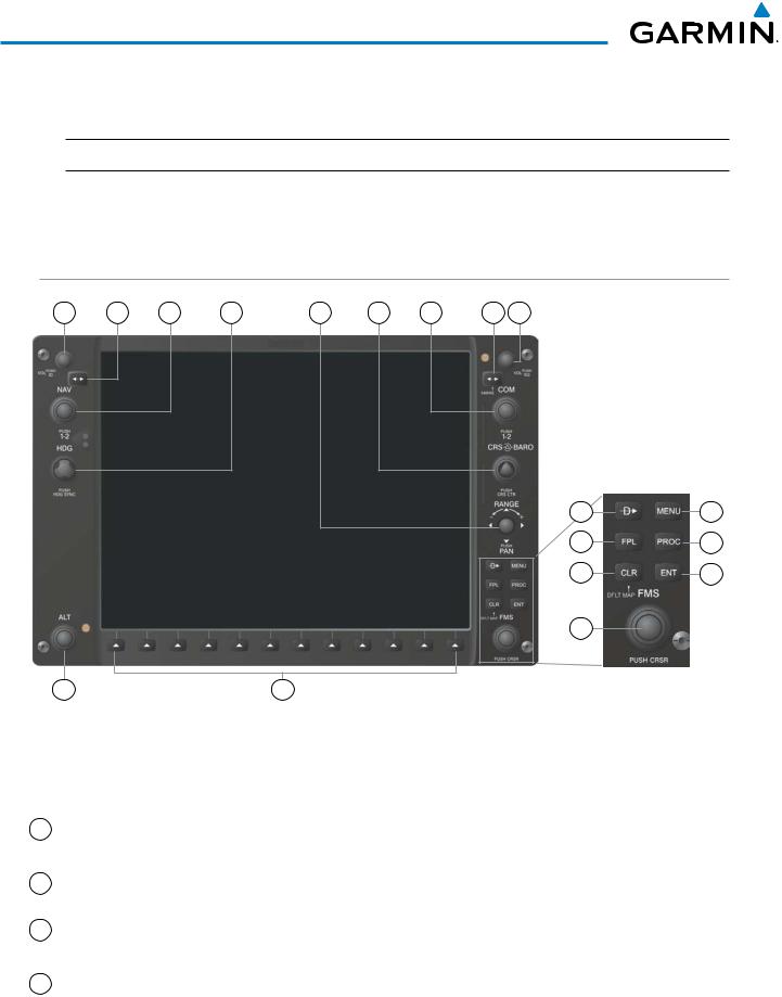
PFD CONTROLS
1 |
2 |
3 |
4 |
5 |
6 |
7 |
8 |
9 |
10 |
13 |
11 |
14 |
12 |
15 |
16 |
|
18 |
17 |
Figure 1-2 PFD/MFD Controls
The following list provides an overview of the controls located on the PFD bezel (see Figure 1-2).
1 NAV VOL/ID Knob Turn to control NAV audio volume (shown in the NAV Frequency Box as a percentage) Press to toggle Morse code identifier audio ON/OFF
2NAV Frequency Transfers the standby and active NAV frequencies
Transfer Key
3 |
NAV Knob |
Turn to tune NAV receiver standby frequencies (large knob for MHz; small for kHz) |
|
|
Press to toggle light blue tuning box between NAV1 and NAV2 |
4 |
Heading Knob |
Turn to manually select a heading |
Press to display a digital heading momentarily to the left of the HSI and synchronize the Selected Heading to the and current heading
6 |
Garmin G1000H™ Pilot’s Guide for the Bell 407GX |
190-01255-00 Rev. B |

SYSTEM OVERVIEW
5 Joystick |
Turn to change map range |
|
Press to activate Map Pointer for map panning |
6CRS/BARO Knob
7COM Knob
8COM Frequency Transfer Key (EMERG)
9COM VOL/SQ Knob
10Direct-to Key ( )
)
11FPL Key
12CLR Key (DFLT MAP)
13MENU Key
Turn large knob for altimeter barometric pressure setting
Turn small knob to adjust course (only when HSI is in VOR or OBS Mode)
Press to re-center the CDI and return course pointer directly TO bearing of active waypoint/station
Turn to tune COM transceiver standby frequencies (large knob for MHz; small for kHz) Press to toggle light blue tuning box between COM1 and COM2
The selected COM (green) is controlled with the COM MIC Key (Audio Panel). Transfers the standby and active COM frequencies
Press and hold two seconds to tune the emergency frequency (121.5 MHz) automatically into the active frequency field
Turn to control COM audio volume level (shown as a percentage in the COM Frequency Box)
Press to turn the COM automatic squelch ON/OFF
Activates the direct-to function and allows the user to enter a destination waypoint and establish a direct course to the selected destination (specified by identifier, chosen from the active route)
Displays flight plan information
Erases information, cancels entries, or removes menus
Press and hold to display the MFD Navigation Map Page (MFD only).
Displays a context-sensitive list of options for accessing additional features or making setting changes
14 |
PROC Key |
Gives access to IFR departure procedures (DPs), arrival procedures (STARs), and |
|
|
approach procedures (IAPs) for a flight plan or selected airport |
15 |
ENT Key |
Validates/confirms menu selection or data entry |
16 |
FMS Knob |
Press to turn the selection cursor ON/OFF. |
|
(Flight Management Data Entry: With cursor ON, turn to enter data in the highlighted field (large knob |
|
|
System Knob) |
moves cursor location; small knob selects character for highlighted cursor location) |
Scrolling: When a list of information is too long for the window/box, a scroll bar appears, indicating more items to view. With cursor ON, turn large knob to scroll through the list.
Page Selection: Turn knob on MFD to select the page to view (large knob selects a page group; small knob selects a specific page from the group)
17Softkey Selection Press to select softkey shown above the bezel key on the PFD/MFD display
Keys
18 ALT Knob |
Sets the Selected Altitude, shown above the Altimeter (the large knob selects the |
|
thousands, the small knob selects the hundreds) |
190-01255-00 Rev. B |
Garmin G1000H™ Pilot’s Guide for the Bell 407GX |
7 |
SYSTEM OVERVIEW
The NAV, CRS/BARO, COM, FMS, and ALT knobs are concentric dual knobs, each having small (inner) and large (outer) control portion. When a portion of the knob is not specified in the text, either may be used.
Large (Outer)
Knob
Small (Inner)
Knob
Figure 1-3 Dual Concentric Knob
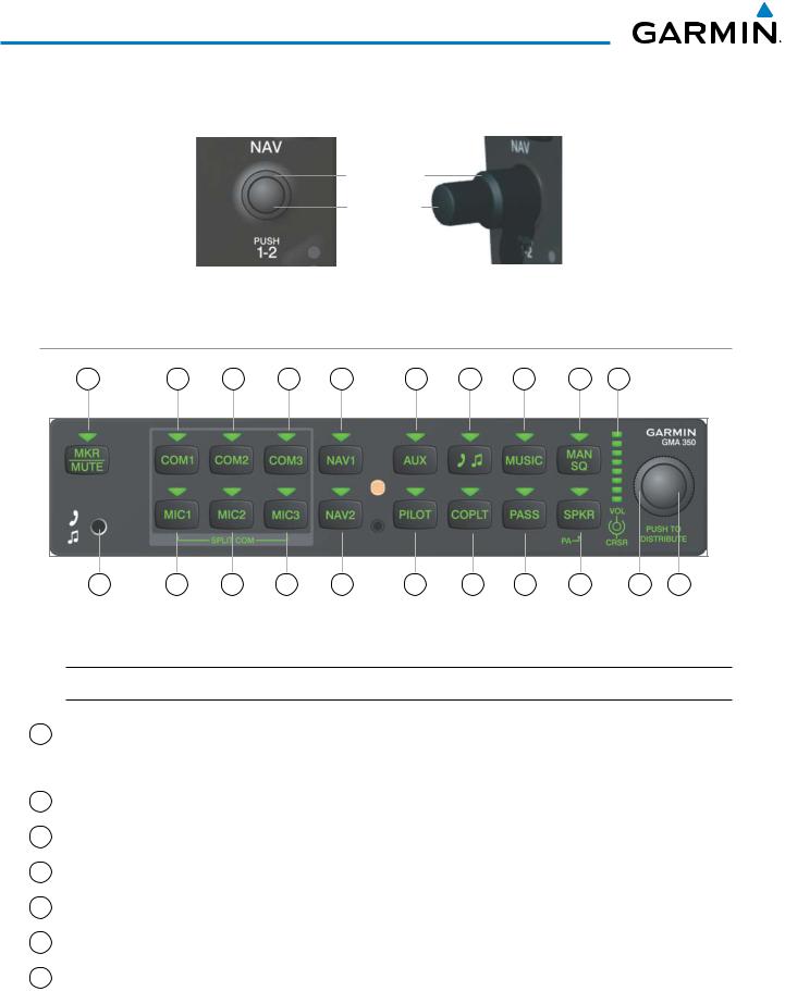
AUDIO PANEL CONTROLS
1 |
2 |
3 |
4 |
5 |
6 |
7 |
8 |
9 |
10 |
11 |
12 |
13 |
14 |
15 |
16 |
17 |
18 |
19 |
20 |
21 |
Figure 1-4 GMA 350H Audio Panel Controls
 NOTE: When a key is selected, an annunciator in the key is illuminated.
1 |
MKR/MUTE Key |
Selects marker beacon receiver audio. Mutes the currently received marker beacon |
|
|
receiver audio. Unmutes automatically when new marker beacon audio is received. |
|
|
Enables Music Mute feature. Also, stops play of recorded COM audio. |
2 |
COM1 Key |
When selected, audio from the #1 COM receiver can be heard. |
3 |
COM2 Key |
When selected, audio from the #2 COM receiver can be heard. |
4 |
COM3 Key |
Reserved for optional COM radio. |
5 |
NAV1 Key |
When selected, audio from the #1 NAV receiver can be heard. |
6 |
AUX Key |
When selected, audio from the AUX input can be heard. |
7 |
Telephone/ |
Selects and deselects telephone and entertainment audio. |
|
Entertainment Key |
|
8 |
Garmin G1000H™ Pilot’s Guide for the Bell 407GX |
190-01255-00 Rev. B |
SYSTEM OVERVIEW
8 |
MUSIC Key |
Selects and deselects music audio. |
9 |
MAN SQ Key |
Manual Squelch annunciator. When lit, squelch is controlled manually. |
10Volume Indicator Indicates volume/squelch setting relative to full scale.
11Front Panel Jack Used for an entertainment or telephone input.
12 |
MIC1 Key |
Selects the #1 transmitter for transmitting. COM1 receive is simultaneously selected |
|
|
when this key is pressed allowing received audio from the #1 COM receiver to be |
|
|
heard. COM2 or COM3 receive can be added by pressing the COM2 or COM3 |
|
|
Key. Selection of a second MIC button initiates Split-COM mode (using COM1/ |
|
|
COM2 or COM1/COM3). When in Split-COM mode, the pilot is using the lower |
|
|
numbered COM, the copilot is using the higher numbered COM. |
13 |
MIC2 Key |
Selects the #2 transmitter for transmitting. COM2 receive is simultaneously selected |
|
|
when this key is pressed allowing received audio from the #2 COM receiver to be |
|
|
heard. COM1 or COM3 receive can be added by pressing the COM1 or COM3 |
|
|
Key. Selection of a second MIC button initiates Split-COM mode (using COM1/ |
|
|
COM2 or COM2/COM3). When in Split-COM mode, the pilot is using the lower |
|
|
numbered COM, the copilot is using the higher numbered COM. |
14 |
MIC3 Key |
Selects the #3 transmitter for transmitting. COM3 receive is simultaneously selected |
|
|
when this key is pressed allowing received audio from the #3 COM receiver to be |
|
|
heard. COM1 or COM2 receive can be added by pressing the COM1 or COM2 |
|
|
Key. Selection of a second MIC button initiates Split-COM mode (using COM1/ |
|
|
COM3 or COM2/COM3). When in Split-COM mode, the pilot is using the lower |
|
|
numbered COM, the copilot is using the higher numbered COM. |
15 |
NAV2 Key |
When selected, audio from the #2 NAV receiver can be heard. |
16 |
PILOT Key |
Selects and deselects the pilot intercom isolation. |
17 |
COPLT Key |
Selects and deselects the copilot intercom isolation. |
18 |
PASS Key |
Selects and deselects the passenger intercom isolation. |
19 |
SPKR Key |
Selects and deselects the cabin speaker. COM and NAV receiver audio can be heard |
|
|
on the speaker. Press and hold for 2 seconds for Passenger Address (PA). The |
|
|
SPKR Key flashes during PA. |
20Cursor (CRSR) Turn to move the cursor (flashing green annunciator) to the desired source.
Control Knob
21Volume (VOL) Turn the smaller knob to control volume or squelch of the selected source (indicated
Control Knob |
by the flashing green annunciator). Press to switch to Blue-Select mode. Blue- |
|
Select mode distributes the Music and Telephone audio to any combination of |
|
headset positions. |
190-01255-00 Rev. B |
Garmin G1000H™ Pilot’s Guide for the Bell 407GX |
9 |

SYSTEM OVERVIEW
1.4 SECURE DIGITAL CARDS
 NOTE: Refer to the Appendices for instructions on updating the aviation database.
 NOTE: Ensure that the G1000H system is powered off before inserting the SD card.
The PFD and MFD data card slots use Secure Digital (SD) cards and are located on the top right portion of the display bezels. Each display bezel is equipped with two SD card slots. SD cards are used for aviation database and system software updates as well as terrain database storage.
Not all SD cards are compatible with the G1000H. Use only SD cards supplied by Garmin or the aircraft manufacturer.
Install an SD card
Insert the SD card in the SD card slot, pushing the card in until the spring latch engages. The front of the card should remain flush with the face of the display bezel.
Remove an SD card
Gently press on the SD card to release the spring latch and eject the card.
SD Card Slots
Figure 1-5 Display Bezel SD Card Slots
10 |
Garmin G1000H™ Pilot’s Guide for the Bell 407GX |
190-01255-00 Rev. B |
SYSTEM OVERVIEW
1.5 SYSTEM POWER-UP
 NOTE: Refer to the Appendices for AHRS initialization bank angle limitations.
 NOTE: See the Appendices for additional information regarding system-specific annunciations and alerts.
NOTE: See the Rotorcraft Flight Manual Supplement (RFMS) for specific procedures concerning avionics power application and emergency power supply operation.
The G1000H system is integrated with the aircraft electrical system and receives power directly from electrical busses. The G1000H PFD, MFD and supporting sub-systems include both power-on and continuous built-in test features that exercise the processor, RAM, ROM, external inputs and outputs to provide safe operation.
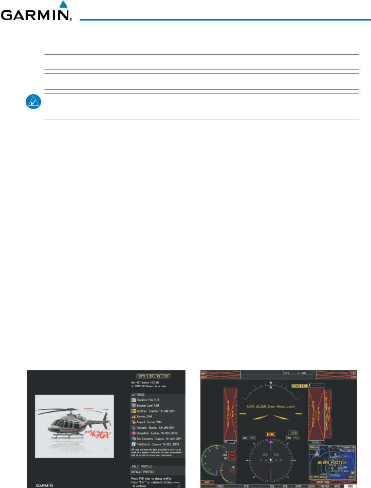
During system initialization, test annunciations are displayed, as shown in Figure 1-7. ALTN is also displayed on the Power Situation Indicator and Torque will be marked QA. All system annunciations should disappear typically within one minute of power-up at nomal temperature, but may take as long as 10 minutes at cold temperatures. Upon power-up, key annunciator lights also become momentarily illuminated on the audio panels, the control units and the display bezels.
On the PFD, the AHRS begins to initialize and displays ‘AHRS ALIGN: Keep Wings Level’. The AHRS should display valid attitude and heading fields typically within one minute of power-up. The AHRS can align itself both while taxiing and during level flight.
When the MFD powers up (Figure 1-6), the MFD Power-up Page displays the following information:
• System version |
• Obstacle database name and version |
• Copyright |
• Navigation database name, version, and effective dates |
• Land database name and version |
• Airport Directory name, version and effective dates |
• Safe Taxi database information |
• FliteCharts/ChartView database information |
• Terrain database name and version |
• Pilot Profile selection |
• Airport Terrain database name and version |
|
Current database information includes the valid operating dates, cycle number and database type. When this information has been reviewed for currency (to ensure that no databases have expired), the pilot is prompted to continue. Pressing the ENT Key acknowledges this information and displays the Auxiliary (AUX) Weight Planning Page.
Figure 1-6 MFD Power-up Page |
Figure 1-7 PFD Initialization |
190-01255-00 Rev. B |
Garmin G1000H™ Pilot’s Guide for the Bell 407GX |
11 |
SYSTEM OVERVIEW
1.6 SYSTEM OPERATION
NOTE: In normal operating mode, backlighting can only be adjusted from the PFD. In reversionary mode, it can be adjusted from the remaining display.
The displays are connected together via a single Ethernet bus for high-speed communication. Each IAU is connected to a single display, as shown in Figure 1-1. This allows the units to share information, enabling true system integration.. This section discusses normal and reversionary G1000H display operation, as well as the various AHRS modes and G1000H System Annunciations.
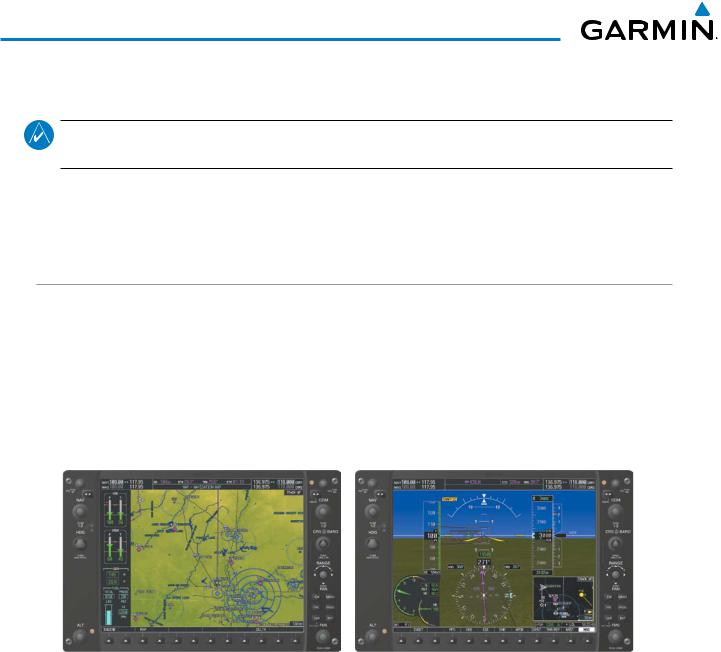
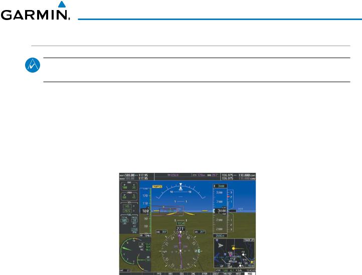
NORMAL DISPLAY OPERATION
In normal operating mode, the PFD presents graphical flight instrumentation (attitude, heading, airspeed, altitude, vertical speed), replacing the traditional flight instrument cluster (see the Flight Instruments Section for more information). The Power Situation Indicator and CAS messages are also displayed on the PFD.
The MFD normally displays a full-color moving map with navigation information (see the Flight Management Section), while the left portion of the MFD is dedicated to the Engine Indication System (EICAS; see the EICAS Section).
Both displays offer control for COM and NAV frequency selection.
Figure 1-8 Normal Mode
12 |
Garmin G1000H™ Pilot’s Guide for the Bell 407GX |
190-01255-00 Rev. B |
SYSTEM OVERVIEW
REVERSIONARY DISPLAY OPERATION
NOTE: The G1000H System alerts the pilot when backup paths are utilized by the LRUs. Refer to Appendix A for further information regarding system-specific alerts.
In the event of a display failure, the G1000H System automatically switches to reversionary (backup) mode. In reversionary mode, all important flight information is presented on the remaining display in the same format as in normal operating mode.
If a display fails, the appropriate IAU Ethernet interface to the display is cut off. Thus, the IAU can no longer communicate with the remaining display (refer to Figure 1-1), and the NAV and COM functions provided to the failed display by the IAU are flagged as invalid on the remaining display. The system reverts to backup paths for the AHRS, ADC, Engine/Airframe Unit, and Transponder, as required. The change to backup paths is completely automated for all LRUs and no pilot action is required.
Figure 1-9 Reversionary Mode
If the system fails to detect a display problem, Reversionary Mode may be manually activated by pressing the red DU BACKUP Button on the instrument panel. Pressing this button again deactivates Reversionary Mode.
190-01255-00 Rev. B |
Garmin G1000H™ Pilot’s Guide for the Bell 407GX |
13 |
SYSTEM OVERVIEW
AHRS OPERATION
 NOTE: Refer to the Appendices for specific AHRS alert information.
 NOTE: Aggressive maneuvering while the AHRS is not operating normally can degrade AHRS accuracy.
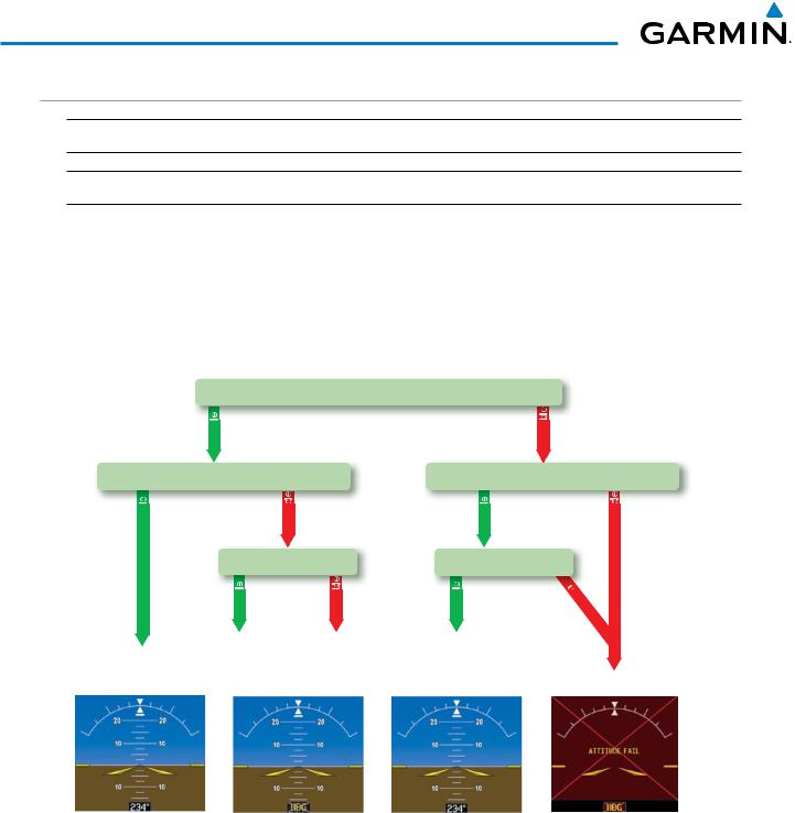
In addition to using internal sensors, the GRS 77H AHRS uses GPS information, magnetic field data and air data to assist in attitude/heading calculations. In normal mode, the AHRS relies upon GPS and magnetic field measurements. In Heading Preset Mode, the magnetometer data is replaced by a heading value set by the pilot. If either of these external measurements is unavailable or invalid, the AHRS uses air data information for attitude determination. Four AHRS modes of operation are available (see Figure 1-10) and depend upon the combination of available sensor inputs. Loss of air data, GPS, or magnetometer sensor inputs is communicated to the pilot by message advisory alerts.
GPS Data
|
availab |
|
|
unavailab |
|
Magnetometer Data |
Magnetometer Data |
||||
availab |
|
unavailab |
availab |
unavailab |
|
|
Air Data |
Air Data |
|||
|
availab |
unavailab |
availab |
una |
|
|
v |
||||
|
ailab |
||||
|
le |
||||
|
|
||||
AHRS Normal |
AHRS no- |
AHRS no-Mag/ |
AHRS |
|
|
Mag Mode |
no-Air Mode |
no-GPS |
|
||
Operation |
Attitude/Heading Invalid |
||||
Heading Invalid |
Mode |
||||
|
|||||
Figure 1-10 AHRS Operation
GPS INPUT FAILURE
The G1000H system provides two sources of GPS information. If a single GPS receiver fails, or if the information provided from one of the GPS receivers is unreliable, the AHRS seamlessly transitions to using the other GPS receiver. An alert message informs the pilot of the use of the backup GPS path. If both GPS inputs fail, the AHRS continues to operate in reversionary No-GPS mode so long as the air data and magnetometer inputs are available and valid.
14 |
Garmin G1000H™ Pilot’s Guide for the Bell 407GX |
190-01255-00 Rev. B |
SYSTEM OVERVIEW
AIR DATA INPUT FAILURE
A failure of the air data input has no effect on AHRS output while AHRS is operating in normal mode. A failure of the air data input while the AHRS is operating in reversionary No-GPS mode results in invalid attitude and heading information on the PFD (as indicated by red “X” flags).
MAGNETOMETER FAILURE
If the magnetometer input fails, the AHRS transitions to one of the reversionary No-Magnetometer modes and continues to output valid attitude information. However, if the aircraft is airborne, the heading output on the PFD does become invalid (as indicated by a red “X”).
G1000H SYSTEM ANNUNCIATIONS
NOTE: For a detailed description of all annunciations and alerts, refer to Appendix A. Refer to the Rotorcraft Flight Manual Supplement (RFMS) for additional information regarding pilot responses to these annunciations.
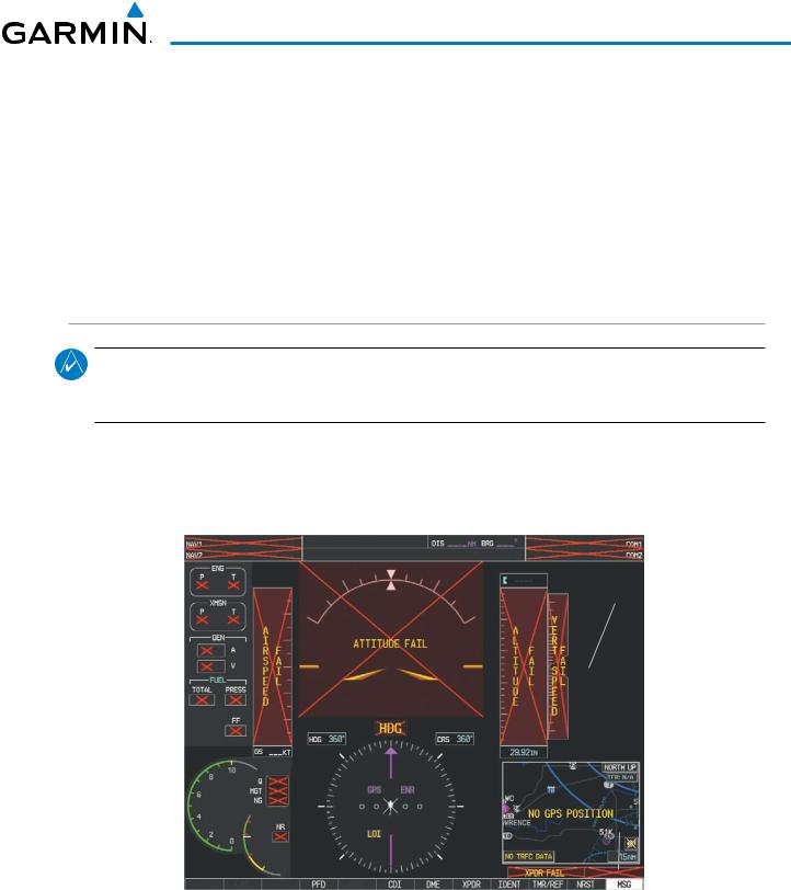
When an LRU or an LRU function fails, a large red “X” is typically displayed on windows associated with the failed data (Figure 1-11 displays all possible flags and responsible LRUs). Upon G1000H power-up, certain windows remain invalid as equipment begins to initialize. If any window remains flagged, the G1000H system should be serviced by a Garmin-authorized repair facility.
GIA 63H Integrated |
|
|
|
|
|
|
|
|
|
|
GIA 63H Integrated |
|||||||
|
|
|
|
|
|
|
||||||||||||
Avionics Units |
|
|
|
|
|
|
|
|
|
|
|
|
Avionics Units |
|||||
|
|
|
|
|
||||||||||||||
|
|
|
|
|
|
|
|
|
|
|
|
|
|
|
|
|
|
GDC 74H Air |
|
|
|
|
|
|
|
|
|
|
|
|
|
|
|
|
|
|
|
|
|
|
|
|
|
|
|
|
|
|
|
|
|
|
|
|
|
Data Computer |
GEA 71H Engine |
|
|
|
|
|
|
|
|
|
|
|
|
|
|
GRS 77H AHRS |
|||
|
|
|
|
|
|
|
|
|
|
|
|
|
|
|
||||
|
|
|
|
|
|
|
|
|
|
|
||||||||
|
|
|
|
|
|
|
|
|
|
|
||||||||
Airframe Unit |
|
|
|
|
|
|
|
|
|
|
|
|
Or |
|||||
|
|
|
|
|
|
|
|
|
|
|
|
|
|
|
|
|||
Or |
|
|
|
|
|
|
|
|
|
|
|
GMU 44 |
||||||
GIA 63W |
|
|
|
|
|
|
|
|
|
|
|
|
Magnetometer |
|||||
Integrated |
|
|
|
|
|
|
|
|
|
|
|
|
||||||
Avionics Unit |
|
|
|
|
|
|
|
|
|
|
|
|
||||||
|
|
|
|
|
|
|
|
|
|
|
|
|
|
|
|
|
|
GIA 63H Integrated |
|
|
|
|
|
|
|
|
|
|
|
|
|
|
|
|
|
|
Avionics Units |
|
|
|
|
|
|
|
|
GDC 74H Air |
|
|
|
|
GTX 33H Transponder |
|||||
|
|
|
|
|
|
|
|
|
|
|
|
|||||||
|
|
|
|
|
|
|
|
|
|
|
|
|
Or |
|||||
|
|
|
|
|
|
|
|
|
|
|
|
|
||||||
|
|
|
|
|
|
|
Data Computer |
|
|
|
GIA 63H Integrated |
|||||||
|
|
|
|
|
|
Figure 1-11 G1000H System Failure Annunciations |
|
|
|
|
Avionics Units |
|||||||
|
|
|
|
|
|
|
|
|
|
|
||||||||
190-01255-00 Rev. B |
Garmin G1000H™ Pilot’s Guide for the Bell 407GX |
15 |
SYSTEM OVERVIEW
SOFTKEY FUNCTION
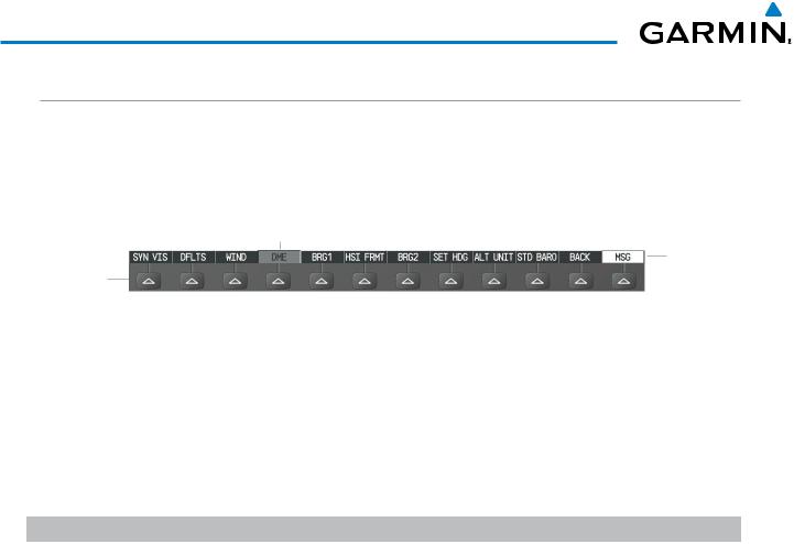
The softkeys are located along the bottoms of the displays. The softkeys shown depend on the softkey level or page being displayed. The bezel keys below the softkeys can be used to select the appropriate softkey. When a softkey is selected, its color changes to black text on gray background and remains this way until it is turned off, at which time it reverts to white text on black background.
Softkey
On
Softkey Names
Bezel-Mounted (Displayed)
Softkeys (Press)
Figure 1-12 Softkeys (Second-Level PFD Configuration)
PFD SOFTKEYS
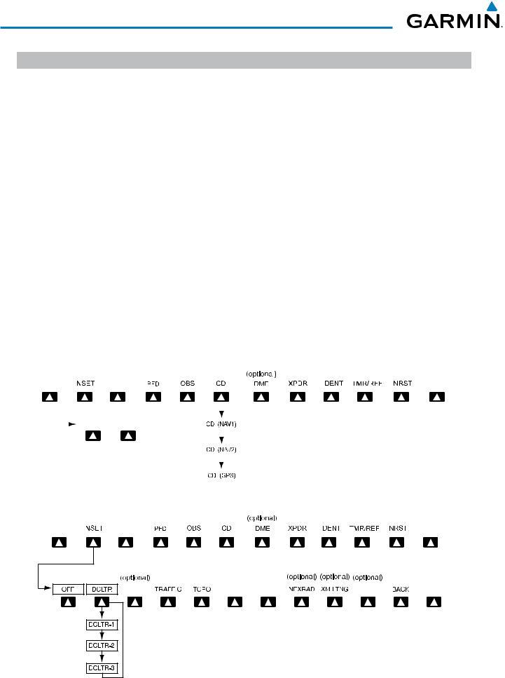
The CDI, IDENT, TMR/REF, NRST, and ALERTS softkeys undergo a momentary change to black text on gray background and automatically switch back to white text on black background when selected.
The PFD softkeys provide control over flight management functions, including GPS, NAV, terrain, traffic, and lightning (optional). Each softkey sublevel has a BACK Softkey which can be selected to return to the previous level. The ALERTS Softkey is visible at all softkey levels (label changes if messages are issued).
Level 1 |
Level 2 |
Level 3 |
Description |
INSET |
|
|
Displays Inset Map in PFD lower left corner |
|
OFF |
|
Removes Inset Map |
|
DCLTR (3) |
|
Selects desired amount of map detail; cycles through declutter levels: |
|
|
|
DCLTR (No Declutter): All map features visible |
|
|
|
DCLTR-1: Declutters land data |
|
|
|
DCLTR-2: Declutters land and SUA data |
|
|
|
DCLTR-3: Removes everything except for the active flight plan |
|
WX LGND |
|
Displays icon and age on the Inset Map for the selected weather products |
|
|
|
(optional) |
|
TRAFFIC |
|
Cycles through traffic display options: |
|
|
|
TRFC-1: Traffic displayed on inset map |
|
|
|
TRFC-2: Traffic Map Page is displayed in the inset map window |
|
|
|
|
|
TOPO |
|
Displays topographical data (e.g., coastlines, terrain, rivers, lakes) and |
|
|
|
elevation scale on Inset Map |
|
NEXRAD |
|
Displays NEXRAD weather and coverage information on Inset Map |
|
|
|
(optional feature) |
|
XM LTNG |
|
Displays XM lightning information on Inset Map (optional feature) |
|
METAR |
|
Displays METAR flags on airport symbols shown on the Inset Map |
|
|
|
(optional) |
16 |
Garmin G1000H™ Pilot’s Guide for the Bell 407GX |
190-01255-00 Rev. B |

SYSTEM OVERVIEW
Level 1 |
Level 2 |
Level 3 |
Description |
PFD |
|
|
Displays second-level softkeys for additional PFD configurations |
|
SYN VIS |
|
Displays the softkeys for enabling or disabling Synthetic Vision |
|
|
|
features |
|
|
PATHWAY |
Displays rectangular boxes representing the horizontal and |
|
|
|
vertical flight path of the active flight plan |
|
|
SYN TERR |
Enables synthetic terrain depiction |
|
|
HRZN HDG |
Displays compass heading along the Zero-Pitch line |
|
|
APTSIGNS |
Displays position markers for airports within approximately |
|
|
|
15 nm of the current aircraft position. Airport identifiers are |
|
|
|
displayed when the airport is within approximately 9 nm. |
|
DFLTS |
|
Resets PFD to default settings, including changing units to standard |
|
|
|
|
|
WIND |
|
Displays softkeys to select wind data parameters |
|
|
OPTN 1 |
Wind direction arrow and speed |
|
|
OPTN 2 |
Wind direction arrow with headwind and crosswind components |
|
|
OPTN 3 |
Wind direction arrow with direction and speed |
|
|
OFF |
Information not displayed |
|
DME |
|
Displays the DME Information Window (optional) |
|
|
|
|
|
BRG1 |
|
Cycles the Bearing 1 Information Window through NAV1, GPS/ waypoint |
|
|
|
identifier and GPS-derived distance information, and ADF/frequency |
|
HSI FRMT |
|
Provides access to the HSI formatting softkeys |
|
|
|
|
|
|
360 HSI |
Displays the HSI in a 360 degree view |
|
|
|
|
|
|
ARC HSI |
Displays the HSI as an arc |
|
|
|
|
|
BRG2 |
|
Cycles the Bearing 2 Information Window through NAV2 or GPS |
|
|
|
waypoint identifier and GPS-derived distance information, and ADF/ |
|
|
|
frequency. |
|
SET HDG |
|
Enables Heading Preset Mode |
|
|
HDG SYNC |
Synchronizes heading to the selected heading |
|
|
HDG - |
Slews heading counterclockwise |
|
|
HDG + |
Slews heading clockwise |
|
|
HPM OFF |
Manually disables Heading Preset Mode |
|
ALT UNIT |
|
Displays softkeys for setting the altimeter and BARO settings to |
|
|
|
metric units |
|
|
METERS |
When enabled, displays altimeter in meters |
|
|
IN |
Press to display the BARO setting as inches of mercury |
|
|
HPA |
Press to display the BARO setting as hectopacals |
|
STD BARO |
|
Sets barometric pressure to 29.92 in Hg (1013 hPa if METRIC softkey is |
|
|
|
selected) |
OBS |
|
|
Selects OBS mode on the CDI when navigating by GPS (only available |
|
|
|
with active leg) |
190-01255-00 Rev. B |
Garmin G1000H™ Pilot’s Guide for the Bell 407GX |
17 |
SYSTEM OVERVIEW
Level 1 |
|
Level 2 |
Level 3 |
|
|
|
|
|
|
|
|
|
|
Description |
||||||||||||||||||||||
CDI |
|
|
|
|
|
|
|
|
|
|
|
|
|
Cycles through GPS, VOR1, and VOR2 navigation modes on the CDI |
||||||||||||||||||||||
DME |
|
|
|
|
|
|
|
|
|
|
|
|
|
Displays the DME Tuning Window, allowing selection of the DME |
||||||||||||||||||||||
XPDR |
|
|
|
|
|
|
|
|
|
|
|
|
|
Displays transponder mode selection softkeys |
||||||||||||||||||||||
|
|
|
STBY |
|
|
|
|
|
Selects standby mode (transponder does not reply to any interrogations) |
|||||||||||||||||||||||||||
|
|
|
ON |
|
|
|
|
|
Selects Mode A (transponder replies to interrogations) |
|||||||||||||||||||||||||||
|
|
|
ALT |
|
|
|
|
|
Selects Mode C – altitude reporting mode (transponder replies to |
|||||||||||||||||||||||||||
|
|
|
|
|
|
|
|
|
|
|
|
|
|
|
|
identification and altitude interrogations) |
||||||||||||||||||||
|
|
|
GND |
|
|
|
|
|
Allows manual selection of ground mode in certain conditions |
|||||||||||||||||||||||||||
|
|
|
VFR |
|
|
|
|
|
Automatically enters the VFR code (1200 in the U.S.A. only) |
|||||||||||||||||||||||||||
|
|
|
CODE |
|
|
|
|
|
Displays transponder code selection softkeys 0-7 |
|||||||||||||||||||||||||||
|
|
|
|
|
|
|
|
|
|
|
0 — 7 |
Use numbers to enter code |
||||||||||||||||||||||||
|
|
|
IDENT |
|
|
|
|
|
Activates the Special Position Identification (SPI) pulse for 18 seconds, |
|||||||||||||||||||||||||||
|
|
|
|
|
|
|
|
|
|
|
|
|
|
|
|
identifying the transponder return on the ATC screen |
||||||||||||||||||||
|
|
|
BKSP |
|
|
|
|
|
Removes numbers entered, one at a time |
|||||||||||||||||||||||||||
IDENT |
|
|
|
|
|
|
|
|
|
|
|
|
|
Activates the Special Position Identification (SPI) pulse for 18 seconds, |
||||||||||||||||||||||
|
|
|
|
|
|
|
|
|
|
|
|
|
|
|
|
identifying the transponder return on the ATC screen |
||||||||||||||||||||
TMR/REF |
|
|
|
|
|
|
|
|
|
|
|
|
|
Displays Timer/References Window |
||||||||||||||||||||||
NRST |
|
|
|
|
|
|
|
|
|
|
|
|
|
Displays Nearest Airports Window |
||||||||||||||||||||||
MSG |
|
|
|
|
|
|
|
|
|
|
|
|
|
Displays the Message Window |
||||||||||||||||||||||
|
|
|
|
|
|
|
|
|
|
|
|
|
|
|
|
|
|
|
|
|
|
|
|
|
|
|
|
|
|
|
|
|
|
|
|
|
|
|
|
|
|
|
|
|
|
|
|
|
|
|
|
|
|
|
|
|
|
|
|
|
|
|
|
|
|
|
|
|
|
|
|
|
|
|
|
|
|
|
|
|
|
|
|
|
|
|
|
|
|
|
|
|
|
|
|
|
|
|
|
|
|
|
|
|
|
|
|
|
|
|
|
CAS |
|
|
|
|
|
|
|
|
|
|
|
|
|
|
|
|
|
|
|
|
|
|
|
|
|
|
|
|
|
|
|
|
MSG |
|
|
|
|
|
|
|
|
|
|
|
|
|
|
|
|
|
|
|
|
|
|
|
|
|
|
|
|
|
|
|
|
|
|
|
||||
|
|
|
|
|
|
|
|
|
|
|
|
|
|
|
|
|
|
|
|
|
|
|
|
|
|
|
|
|
|
|
|
|||||
|
|
|
|
|
|
|
|
|
|
|
|
|
|
|
|
|
|
|
|
|
|
|
|
|
|
|
|
|
|
|
|
|
|
|
|
|
|
|
|
|
|
|
|
|
|
|
|
|
|
|
|
|
|
|
|
|
|
|
|
|
|
|
|
|
|
|
|
|
|
|
|
|
|
|
|
|
|
|
|
|
|
|
|
|
|
|
|
|
|
|
|
|
|
|
|
|
|
|
|
|
|
|
|
|
|
|
|
|
|
|
|
|
|
|
|
|
CAS ↑ |
|
|
CAS ↓ |
|
|
|
|
|
|
|
|
|
|
|
|
|
|
|
|
|
|
|
|
|
|
|
||||
|
|
|
|
|
|
|
|
|
|
|
|
|
|
|
|
|
|
|
|
|
|
|
|
|
|
|
|
|
|
|
||||||
|
|
|
|
|
|
|
|
|
|
|
|
|
|
|
|
|
|
|
|
|
|
|
|
|
|
|
|
|
|
|
|
|
|
|
|
|
|
|
|
|
|
|
|
|
|
|
|
|
|
|
|
|
|
|
|
|
|
|
|
|
|
|
|
|
|
|
|
|
|
|
|
|
|
|
|
|
|
|
|
|
|
|
|
|
|
|
|
|
|
|
|
|
|
|
|
|
|
|
|
|
|
|
|
|
|
|
|
|
|
|
|
|
|
|
|
|
|
|
|
|
|
|
|
|
|
|
|
|
|
|
|
|
|
|
|
|
|
|
|
|
|
|
|
|
|
|
|
|
|
|
|
|
|
|
|
|
|
|
|
|
|
|
|
|
|
|
|
|
|
|
|
|
|
|
|
|
|
|
|
|
|
|
|
|
|
|
|
|
|
|
|
|
|
|
|
|
|
|
|
|
|
|
|
|
|
|
|
|
|
|
|
|
|
|
|
|
|
|
|
|
|
|
|
|
|
|
|
|
|
|
|
|
|
|
|
|
|
|
|
|
|
|
|
|
|
|
|
|
|
|
|
|
|
|
|
|
|
|
|
|
|
|
|
|
|
|
|
|
|
|
|
|
|
|
|
|
|
|
|
|
|
|
|
|
|
|
|
|
|
|
|
|
|
|
|
|
|
|
|
|
|
|
|
|
|
|
|
|
|
|
|
|
|
|
|
|
|
|
|
|
|
|
|
|
|
|
|
|
|
|
|
|
|
|
|
|
|
|
|
|
|
|
|
|
|
|
|
|
|
|
|
|
|
|
|
|
|
|
|
|
|
|
|
|
|
|
|
|
|
|
|
|
|
|
|
|
|
|
|
|
|
|
|
|
|
|
|
|
|
|
|
|
|
|
|
|
|
|
|
|
|
|
|
|
|
|
Figure 1-13 Top Level PFD Softkeys
CAS |
|
|
|
|
|
|
|
|
|
|
|
|
|
|
|
|
|
|
|
|
|
|
|
|
MSG |
|
|
|
|
|
|
|
|
|
|
|
|
|
|
|
|
|
|
|
|
|
|
|
WX LGND |
|
|
|
|
|
|
|
|
|
|
|
|
|
|
METAR |
|
|
MSG |
|
|
|
|
|
|
|
|
|
|
|
|
|
|
Press the BACK Softkey to return to the top-level softkeys.
Figure 1-14 INSET Softkeys
18 |
Garmin G1000H™ Pilot’s Guide for the Bell 407GX |
190-01255-00 Rev. B |
Loading...