

Page 1

TM
G1000
Pilot’s Guide
for the Diamond DA40
Page 2
Part Number Change Summary
190-00592-00
(Rev. A)
Reformatted for single part number (all previous part numbers incorporated into this part number)
Added optional fuel pressure indicator information
Record of Revisions
Revision Date of Revision Revision Page Range Description
A 11/10/05 i through I-6 Initial release.
Garmin G1000 Pilot’s Guide For the Diamond DA40
190-00592-00 Rev. A
Page 3

Copyright © 2005 Garmin Ltd. or its subsidiaries. All rights reserved.
COPYRIGHT
This manual reflects the operation of
System Software version 0369.09 or later for the DA40, DA40F and System Software version
0370.13 or later for the DA40D. Some differences in operation may be observed when comparing the information in this manual to
earlier or later software versions.
Garmin International, Inc., 1200 East 151st Street, Olathe, Kansas 66062, U.S.A.
Tel: 913/397.8200 Fax: 913/397.8282
Garmin AT, Inc., 2345 Turner Road SE, Salem, OR 97302, U.S.A.
Tel: 503/391.3411 Fax 503/364.2138
Garmin (Europe) Ltd., Unit 5, The Quadrangle, Abbey Park Industrial Estate, Romsey, Hampshire S051 9DL, U.K.
Tel: 44/0870.8501241 Fax: 44/0870.8501251
Garmin Corporation, No. 68, Jangshu 2nd Road, Shijr, Taipei County, Taiwan
Tel: 886/02.2642.9199 Fax: 886/02.2642.9099
Web Site Address: www.garmin.com
Except as expressly provided herein, no part of this manual may be reproduced, copied, transmitted, disseminated, downloaded or
stored in any storage medium, for any purpose without the express written permission of Garmin. Garmin hereby grants permission
to download a single copy of this manual and of any revision to this manual onto a hard drive or other electronic storage medium to
be viewed for personal use, provided that such electronic or printed copy of this manual or revision must contain the complete text
of this copyright notice and provided further that any unauthorized commercial distribution of this manual or any revision hereto is
strictly prohibited.
Garmin® is a registered trademark of Garmin Ltd. or its subsidiaries, and G1000™ is a trademark of Garmin Ltd. or its subsidiaries.
These trademarks may not be used without the express permission of Garmin.
Bendix/King® and Honeywell® are registered trademarks of Honeywell International, Inc.; Becker® is a registered trademark of Becker
Flugfunkwerk GmbH; NavData
TCAD® is a registered trademark of Ryan International, Inc. and XM® is a registered trademark of XM Satellite Radio, Inc..
tions;
November 2005 Printed in the U.S.A.
190-00592-00 Rev. A
®
is a registered trademark of Jeppesen, Inc.; Stormscope® is a registered trademark of L-3 Communica-
Garmin G1000 Pilot’s Guide For the Diamond DA40
i
Page 4
WARNINGS & CAUTIONS
WARNING: Navigation and terrain separation must NOT be predicated upon the use of the terrain function.
The G1000 Terrain Proximity feature is NOT intended to be used as a primary reference for terrain avoidance
and does not relieve the pilot from the responsibility of being aware of surroundings during flight. The Terrain
Proximity feature is only to be used as an aid for terrain avoidance and is not certified for use in applications
requiring a certified terrain awareness system. Terrain data is obtained from third party sources. Garmin is
not able to independently verify the accuracy of the terrain data.
WARNING: The displayed minimum safe altitudes (MSAs) are only advisory in nature and should not be relied
upon as the sole source of obstacle and terrain avoidance information. Always refer to current aeronautical
charts for appropriate minimum clearance altitudes.
WARNING: The Garmin G1000, as installed in Diamond DA40, DA40F and DA40D aircraft, has a very high
degree of functional integrity. However, the pilot must recognize that providing monitoring and/or self-test
capability for all conceivable system failures is not practical. Although unlikely, it may be possible for erroneous
operation to occur without a fault indication shown by the G1000. It is thus the responsibility of the pilot to
detect such an occurrence by means of cross-checking with all redundant or correlated information available
in the cockpit.
WARNING: For safety reasons, G1000 operational procedures must be learned on the ground.
WARNING: The altitude calculated by G1000 GPS receivers is geometric height above Mean Sea Level and could
vary significantly from the altitude displayed by pressure altimeters, such as the GDC 74A Air Data Computer,
or other altimeters in aircraft. GPS altitude should never be used for vertical navigation. Always use pressure
altitude displayed by the G1000 PFD or other pressure altimeters in aircraft.
WARNING: The Jeppesen database used in the G1000 system must be updated regularly in order to ensure
that its information remains current. Updates are released every 28 days. A database information packet is
included in the G1000 package. Pilots using an outdated database do so entirely at their own risk.
WARNING: The basemap (land and water data) must not be used for navigation, but rather only for non-navigational situational awareness. Any basemap indication should be compared with other navigation sources.
CAUTION: The illustrations in this guide are only examples. Never use the G1000 to attempt to penetrate
a thunderstorm. Both the FAA Advisory Circular, Subject: Thunderstorms, and the Aeronautical Information
Manual (AIM) recommend avoiding “by at least 20 miles any thunderstorm identified as severe or giving an
intense radar echo.”
Garmin G1000 Pilot’s Guide For the Diamond DA40
190-00592-00 Rev. Aii
Page 5
WARNINGS & CAUTIONS
CAUTION: The United States government operates the Global Positioning System and is solely responsible
for its accuracy and maintenance. The GPS system is subject to changes which could affect the accuracy and
performance of all GPS equipment. Portions of the Garmin G1000 utilize GPS as a precision electronic NAVigation AID (NAVAID). Therefore, as with all NAVAIDs, information presented by the G1000 can be misused or
misinterpreted and, therefore, become unsafe.
CAUTION: To reduce the risk of unsafe operation, carefully review and understand all aspects of the G1000
Pilot’s Guide documentation and the G1000 Flight Manual Supplement. Thoroughly practice basic operation
prior to actual use. During flight operations, carefully compare indications from the G1000 to all available
navigation sources, including the information from other NAVAIDs, visual sightings, charts, etc. For safety
purposes, always resolve any discrepancies before continuing navigation.
CAUTION: The Garmin G1000 does not contain any user-serviceable parts. Repairs should only be made by
an authorized Garmin service center. Unauthorized repairs or modifications could void both the warranty and
the pilot’s authority to operate this device under FAA/FCC regulations.
CAUTION: The GDU PFD and MFD displays use a lens coated with a special anti-reflective coating that is very
sensitive to skin oils, waxes, and abrasive cleaners. CLEANERS CONTAINING AMMONIA WILL HARM THE ANTIREFLECTIVE COATING. It is very important to clean the lens using a clean, lint-free cloth and an eyeglass lens
cleaner that is specified as safe for anti-reflective coatings.
190-00592-00 Rev. A
NOTE: All visual depictions contained within this document, including screen images of the G1000 panel and
displays, are subject to change and may not reflect the most current G1000 system. Depictions of equipment
may differ slightly from the actual equipment.
NOTE: This device complies with part 15 of the FCC Rules. Operation is subject to the following two conditions:
(1) this device may not cause harmful interference, and (2) this device must accept any interference received,
including interference that may cause undesired operation.
NOTE: There are several atmospheric phenomena in addition to nearby thunderstorms that can cause isolated
discharge points in the strike display mode. However, clusters of two or more discharge points in the strike
display mode do indicate thunderstorm activity if these points reappear after the screen has been cleared.
Avoid the clusters to avoid the thunderstorms. In the cell display mode, even a single discharge point may
represent thunderstorm activity and should therefore be avoided.
Garmin G1000 Pilot’s Guide For the Diamond DA40
iii
Page 6

WARRANTY
LIMITED WARRANTY
This Garmin product is warranted to be free from defects in materials or workmanship for two years from the date of purchase. Within this
period, Garmin will, at its sole option, repair or replace any components that fail in normal use. Such repairs or replacement will be made at no
charge to the customer for parts and labor, provided that the customer shall be responsible for any transportation cost. This warranty does not
cover failures due to abuse, misuse, accident, or unauthorized alterations or repairs.
THE WARRANTIES AND REMEDIES CONTAINED HEREIN ARE EXCLUSIVE AND IN LIEU OF ALL OTHER WARRANTIES EXPRESS OR IMPLIED OR
STATUTORY, INCLUDING ANY LIABILITY ARISING UNDER ANY WARRANTY OF MERCHANTABILITY OR FITNESS FOR A PARTICULAR PURPOSE,
STATUTORY OR OTHERWISE. THIS WARRANTY GIVES YOU SPECIFIC LEGAL RIGHTS, WHICH MAY VARY FROM STATE TO STATE.
IN NO EVENT SHALL GARMIN BE LIABLE FOR ANY INCIDENTAL, SPECIAL, INDIRECT OR CONSEQUENTIAL DAMAGES, WHETHER RESULTING
FROM THE USE, MISUSE, OR INABILITY TO USE THIS PRODUCT OR FROM DEFECTS IN THE PRODUCT. Some states do not allow the exclusion of
incidental or consequential damages, so the above limitations may not apply to you.
Garmin retains the exclusive right to repair or replace the unit or software, or to offer a full refund of the purchase price, at its sole discretion.
SUCH REMEDY SHALL BE YOUR SOLE AND EXCLUSIVE REMEDY FOR ANY BREACH OF WARRANTY.
To obtain warranty service, contact your local Garmin Authorized Service Center. For assistance in locating a Service Center near you, visit the
Garmin Web site at “http://www.garmin.com”
or contact Garmin Customer Service at 800-800-1020.
Garmin G1000 Pilot’s Guide For the Diamond DA40
190-00592-00 Rev. Aiv
Page 7

TABLE OF CONTENTS
1 – SYSTEM OVERVIEW
1.1 System Description ......................................... 1-1
1.2 LRU Descriptions ............................................ 1-1
1.3 PFD/MFD Controls ......................................... 1-6
1.4 Secure Digital Cards ....................................... 1-8
1.5 System Power-up ............................................ 1-9
1.6 Display Backlighting ......................................1-11
1.7 System Operation ..........................................1-11
Normal Operation ....................................................1-11
Reversionary Mode ..................................................1-12
AHRS Modes of Operation .......................................1-13
1.8 Checklists (optional) ......................................1-14
1 – PRIMARY FLIGHT DISPLAY
2.1 Introduction .................................................... 2-1
2.2 Backlighting ................................................... 2-4
2.3 Softkey Function ............................................ 2-5
2.4 Flight Instruments .......................................... 2-9
Airspeed Indicator ......................................................2-9
Attitude Indicator .....................................................2-10
Altimeter ..................................................................2-12
Vertical Deviation/Glideslope Indicator ....................
Marker Beacon Annunciations ..................................
Vertical Speed Indicator ...........................................
Horizontal Situation Indicator ..................................2-15
2-14
2-14
2-14
2.5 Communication, Navigation, & Surveillance .2-22
Communication Frequency Window .........................
Navigation Frequency Window .................................
Navigation Status Bar ..............................................2-23
Transponder (XPDR) Status Bar ................................
2-22
2-22
2-23
2.6 Supplemental Flight Data ..............................2-24
Outside Air Temperature Box ....................................
System Time Box ......................................................
Inset Map .................................................................2-24
2-24
2-24
Auxiliary Window Keys .............................................2-27
Working with Menus ................................................
Auxiliary Windows ....................................................
2-28
2-28
2.7 Reversionary Mode .......................................2-43
2.8 Alerts and Annunciations ...............................2-44
Alerts Window ..........................................................
Annunciation Window ..............................................
Softkey Annunciations ..............................................
Traffic Annunciation .................................................
2-44
2-44
2-44
2-45
3 – NAV/COM
3.1 NAV/COM Introduction ................................... 3-1
Windows and Fields ...................................................
Radio Selection ...........................................................3-2
Controls ......................................................................3-3
Tuning Box .................................................................
Switching Between Radios .........................................3-4
Manually Tuning a Frequency .....................................
Radio Indicators .........................................................3-5
Volume .......................................................................
Frequency Transfer Arrow ...........................................
3-2
3-4
3-4
3-5
3-5
3.2 COM Operation ............................................... 3-6
Frequency Spacing ......................................................
Automatic Squelch .....................................................3-6
Selecting a COM Radio ...............................................3-6
Emergency Frequency (
Quick-Tuning and Activating
Stuck Microphone ......................................................3-7
121.500 MHz) ........................3-7
121.500 MHz ................3-7
3-6
3.3 NAV operation ................................................ 3-8
Frequency
Morse Code Identifier .................................................
NAV
Range ........................................................3-8
3-8
Radio Selection for Navigation ...........................3-8
3.4 Optional Radios .............................................. 3-9
Overview ....................................................................3-9
ADF/DME Tuning Window ..........................................3-9
190-00592-00 Rev. A
Garmin G1000 Pilot’s Guide For the Diamond DA40
v
Page 8

TABLE OF CONTENTS
3.5 Frequency Auto-Tuning ..................................3-13
Auto-Tuning on the
Auto-Tuning on the
Auto-Tuning Upon Approach Activation (NAV
Frequencies) .............................................................
PFD ...........................................3-13
MFD ..........................................3-14
3-20
4 – TRANSPONDER
4.1 Transponder Description ................................. 4-1
Transponder Softkeys .................................................
Transponder Status Bar ..............................................
Mode S Features .........................................................
Traffic Information Service (TIS) ..................................
4-1
4-1
4-2
4-2
4.2 Operation ....................................................... 4-3
Mode Selection ..........................................................4-3
Code Selection ...........................................................4-4
IDENT Function ..........................................................4-5
5 – AUDIO PANEL
5.1 Audio Panel Description ................................. 5-1
Transceivers ................................................................
Mono/Stereo Headsets ...............................................5-2
Unmuted/Unswitched Inputs ......................................5-2
Audio Panel Controls ..................................................5-2
5-1
5.2 Operation ....................................................... 5-4
Power-Up and Fail-Safe
Key A
nnunciators ........................................................5-4
Lighting ......................................................................5-4
Transceiver Keys .........................................................
PA Function ................................................................
Speaker ......................................................................
Marker Beacon Receiver .............................................
Navigation Radios ......................................................5-6
Intercom System (ICS) Isolation ..................................5-7
Intercom Volume and Squelch ....................................5-8
Master Avionics Squelch (MASQ) ...............................
Digital Clearance Recorder with Playback Capability .5-9
Operation .............................5-4
5-4
5-5
5-5
5-5
5-8
Reversionary Mode ....................................................5-9
6 – ENGINE INDICATION SYSTEM
6.1 Introduction .................................................... 6-1
EIS Pages ....................................................................
EIS Indicators ..............................................................6-1
6-1
6.2 DA40 & DA40F ................................................ 6-2
Engine Page ................................................................
Lean Page ...................................................................6-4
System Page ...............................................................
6-2
6-6
6.3 DA40D ............................................................. 6-8
Engine Page ................................................................
System Page .............................................................
Fuel Page ..................................................................
6-8
6-10
6-11
7 – MULTI FUNCTION DISPLAY
7.1 Introduction .................................................... 7-1
Description .................................................................7-1
MFD Power-Up ...........................................................
MFD Backlighting .......................................................7-1
MFD Softkeys ............................................................
Electronic Checklists (optional) ..................................7-3
MFD Page Groups ......................................................
Working With
Menus ..................................................7-6
7-1
7-2
7-5
7.2 Navigation Map Page ..................................... 7-7
Navigation Map Page Operations ..............................
7-8
7.3 Traffic Map Page ............................................7-27
TIS Symbology ..........................................................7-28
Traffic Map Page Operations ....................................
7-28
7.4 Terrain Proximity Page ...................................7-31
Terrain Proximity Page Operations ...........................
Displaying Obstacle Data .........................................7-33
7-32
7.5 Direct-to Navigation ......................................7-34
Direct-to Navigation Operations ...............................7-35
7.6 Flight Plans ....................................................7-39
Garmin G1000 Pilot’s Guide For the Diamond DA40
190-00592-00 Rev. Avi
Page 9

TABLE OF CONTENTS
Active Flight Plan Page .............................................7-39
Active Flight Plan Page Options ...............................
Flight Plan Catalog Page ..........................................
Flight Plan Catalog Page Operations .......................
Vertical Navigation (VNAV) Page ..............................
7-40
7-49
7-49
7-55
7.7 Procedures .....................................................7-57
Arrivals and Departures ............................................
Approaches ..............................................................7-58
G1000 Navigational Guidance for Approaches ........
Selecting Approaches ...............................................
7-57
7-58
7-59
7.8 Waypoint Page Group ....................................7-61
Airport Information Page (INFO) ..............................7-62
Airport Frequency Information Field .........................
AIRPORT Information Page Options .........................
Departure Information Page (DP) .............................
Arrival Information Page (STAR) ...............................
Approach Information Page ......................................
Intersection Information Page ..................................7-71
NDB Information Page ..............................................
VOR Information Page ..............................................
User Waypoint Information Page ..............................
Creating User Waypoints ..........................................
Modifying User Waypoints .......................................
User Waypoint Information Page Options .................
7-65
7-66
7-67
7-68
7-69
7-73
7-75
7-77
7-78
7-80
7-81
7.9 Auxiliary Page Group .....................................7-84
Trip Planning Page ....................................................
GPS Status Page .......................................................7-91
System Setup Page ...................................................
System Status Page ................................................
7-85
7-95
7-104
7.10 Nearest Page Group ..................................7-105
Nearest Airports Page .............................................
Nearest Intersections Page .....................................
Nearest NDB Page ..................................................
Nearest VOR Page ..................................................
Nearest User Waypoint Page ..................................
Nearest Frequencies Page .......................................
7-107
7-109
7-110
7-111
7-113
7-114
Nearest Airspaces Page ..........................................7-115
8 – OPTIONAL EQUIPMENT
8.1 Introduction .................................................... 8-1
8.2 Stormscope ...................................................... 8-2
Displaying Stormscope Lightning Data on the Navigation
Map Page ...................................................................8-2
Stormscope Page ........................................................
8-5
8.3 Traffic Advisory Systems ................................ 8-7
Introduction ................................................................8-7
L-3 SKYWATCH Traffic Advisory Systems (SKY497 and
SKY899) ....................................................................8-9
Honeywell KTA 870/KMH 880 .................................8-10
Ryan 9900B/BX .......................................................8-11
8.4 GDL 69/69A ...................................................8-12
Introduction ..............................................................8-12
GDL 69/69A Weather ...............................................
Weather Product Symbols ........................................
GDL 69/69A – XM Digital Audio Entertainment .......
XM Radio Page .........................................................8-24
GDL 69/69A Troubleshooting ....................................8-27
8-12
8-21
8-23
9 – ANNUNCIATIONS AND ALERTS
9.1 Introduction .................................................... 9-1
9.2 Alert Level Definitions .................................... 9-2
9.3 DA40 & DA40F Aircraft Alerts ......................... 9-3
9.4 DA40D Aircraft Alerts ..................................... 9-5
9.5 G1000 System Annunciations ......................... 9-7
9.6 G1000 System Message Advisories ...............9-10
APPENDICES
Appendix A SD Card Use ......................................A-1
Aviation Database ..................................................... A-1
Terrain and Obstacle Databases ................................
A-1
Appendix B Glossary ............................................B-1
190-00592-00 Rev. A
Garmin G1000 Pilot’s Guide For the Diamond DA40
vii
Page 10

TABLE OF CONTENTS
Appendix C Questions & Answers ........................C-1
Appendix D G1000 Map Datums ..........................D-1
Appendix E General TIS Information .................... E-1
Introduction ................................................................E-1
TIS vs. TCAS ................................................................
TIS Limitations ............................................................E-1
Appendix F Map Symbols ..................................... F-1
Airport ........................................................................F-1
NAVAIDS ....................................................................
Basemap ....................................................................F-1
Traffic .........................................................................
Lightning Strike .......................................................... F-2
Impact Points (TAWS Only) .........................................
Miscellaneous ............................................................F-2
Line Symbols ..............................................................F-3
Obstacle database ..................................................... F-4
Terrain Color Chart .....................................................
Appendix G G1000 System Specifications ...........G-1
GDU 1040 MFD & PFD ..............................................G-1
GMA 1347 Audio Panel .............................................
GIA 63 Integrated Avionics Units ..............................
GDC 74A Air Data Computer .....................................
GTX 33 Mode S Transponder .....................................
GEA 71 Engine/Airframe Unit .................................... G-2
GDL 69/69A Weather Data Link .................................
GRS 77 AHRS .............................................................
E-1
F-1
F-2
F-2
F-4
G-1
G-1
G-2
G-2
G-2
G-3
INDEX
Garmin G1000 Pilot’s Guide For the Diamond DA40
190-00592-00 Rev. Aviii
Page 11

TM
G1000
System Overview
Page 12

190-00592-00 Rev. AGarmin G1000 Pilot’s Guide for the Diamond DA40
Page 13
SYSTEM OVERVIEW
1.1 SYSTEM DESCRIPTION
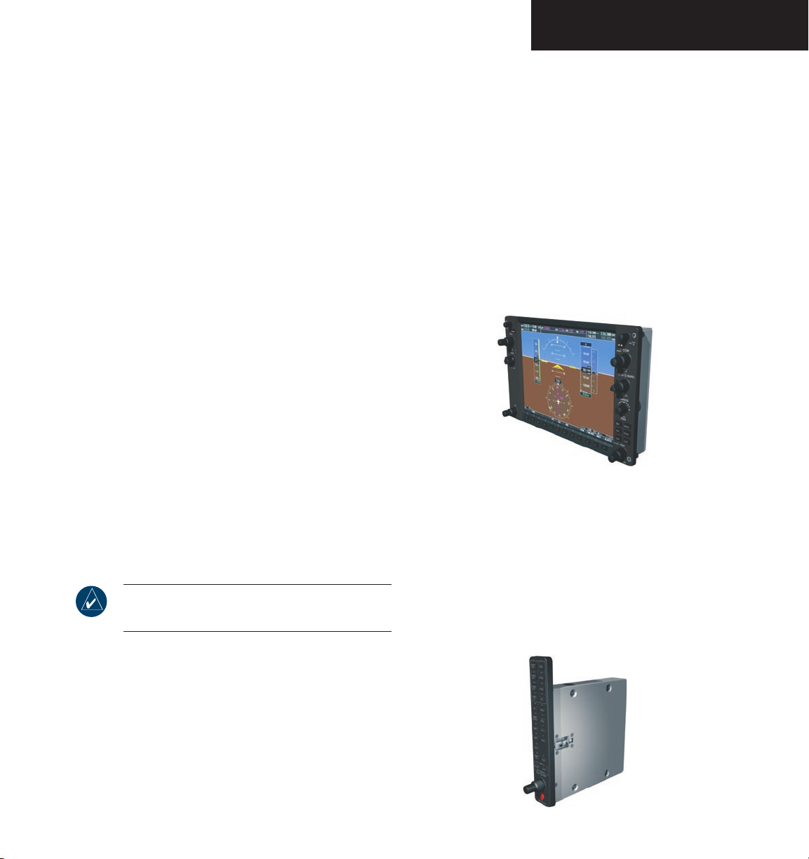
This section provides an overview of the G1000
Integrated Cockpit System as installed in the Diamond
DA40 aircraft.
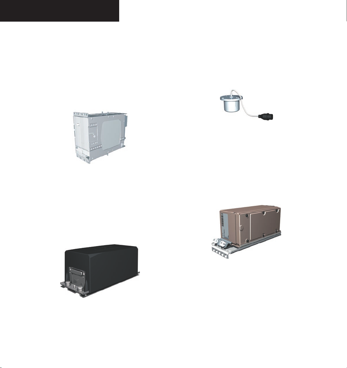
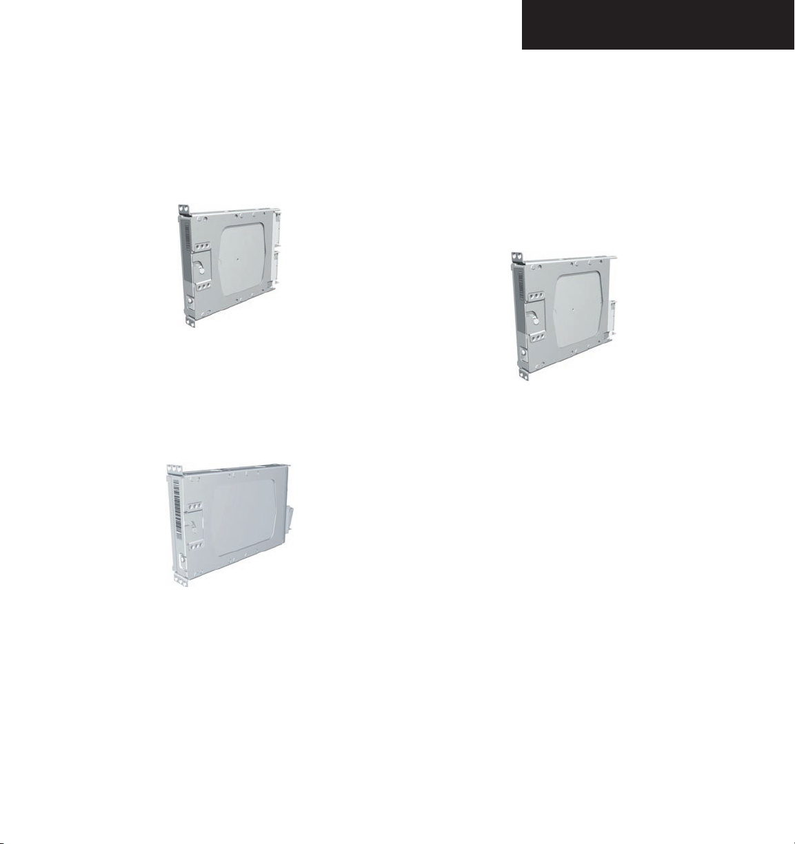
The G1000 uses the following Line Replaceable Units
(LRUs):
• GDU 1040 Primary Flight Display (PFD)
• GDU 1040 Multi Function Display (MFD)
• GIA 63 Integrated Avionics Units (IAU) - 2
• GEA 71 Engine/Airframe Unit
• GDC 74A Air Data Computer (ADC)
• GRS 77 Attitude and Heading Reference System
(AHRS)
• GMU 44 Magnetometer
• GMA 1347 Audio Panel with integrated Marker
Beacon Receiver
• GTX 33 Mode S Transponder
• GDL 69/69A Data Link
The LRUs are further described in the following section.
All LRUs are modular, which greatly eases troubleshooting
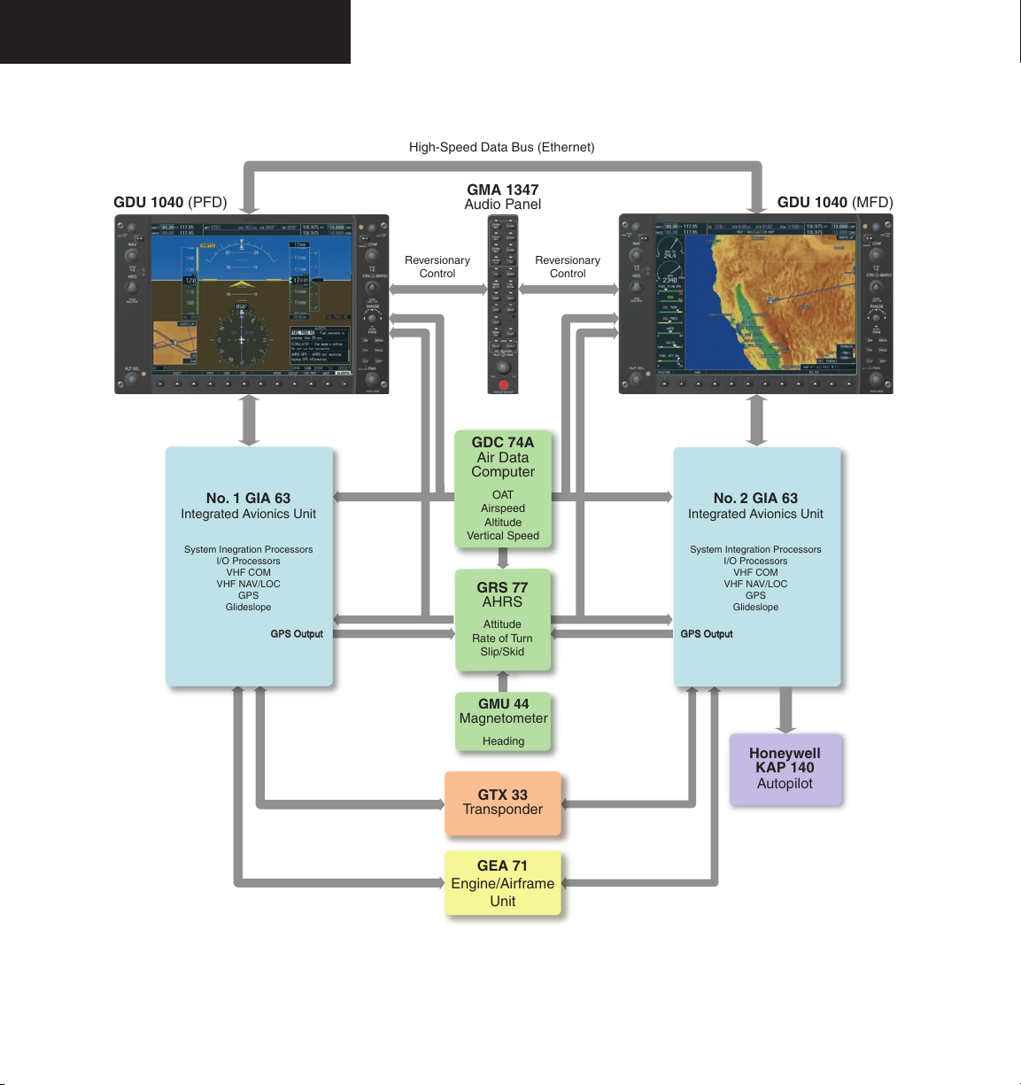
and maintenance of the G1000 System. A top-level G1000
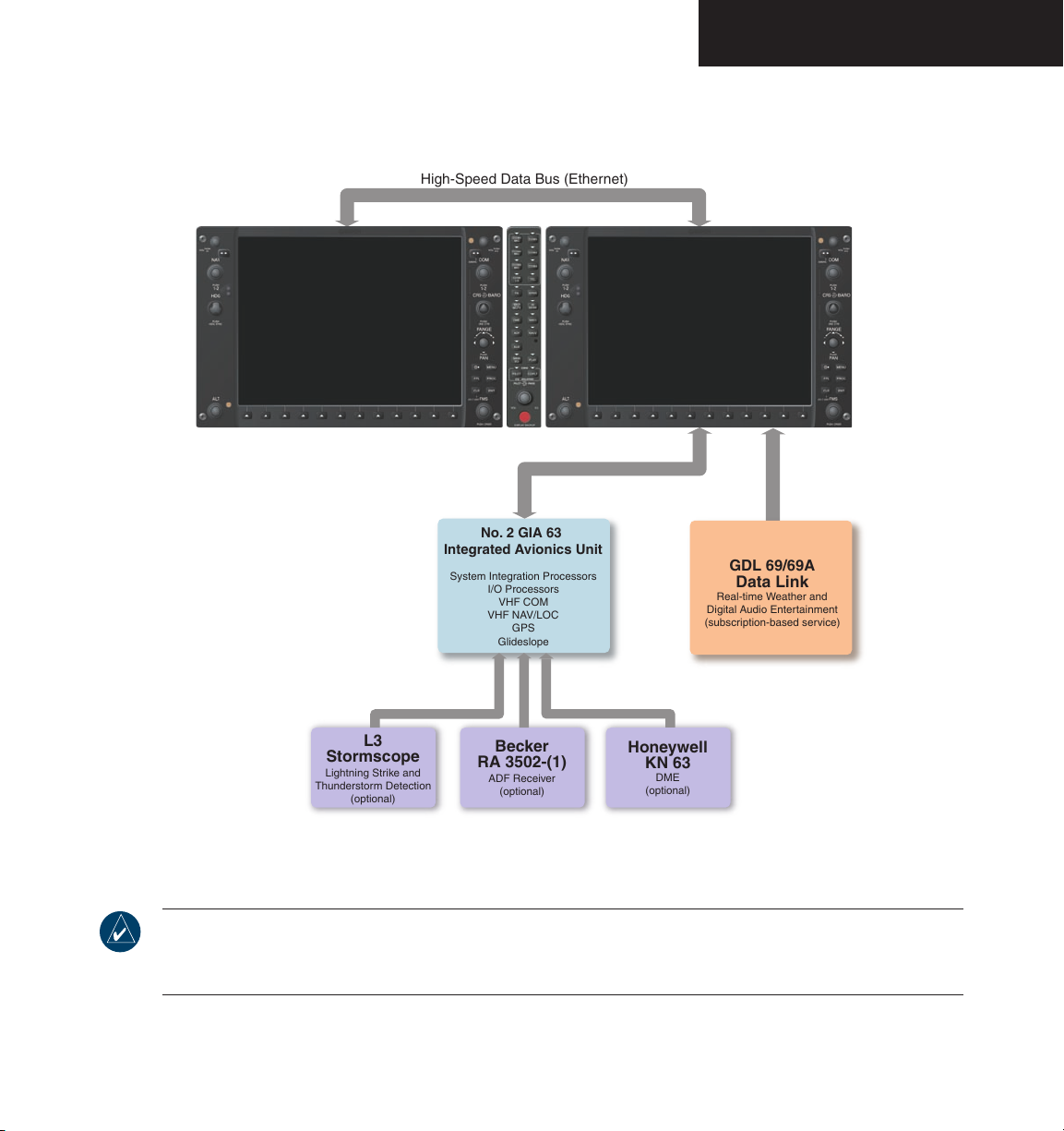
block diagram is given in Figure 1-1. Additional/optional
equipment are shown in Figure 1-2.
NOTE: Refer to the Appendices for G1000 LRU
specifications.
1.2 LRU DESCRIPTIONS
• GDU 1040 – The GDU 1040s have 10.4-inch
LCD displays with 1024 x 768 resolution. The left
display is configured as a PFD and the right display
is configured as a MFD. Both displays link and are
used to show all functions of the G1000 System
during flight. The displays communicate with
each other through a High-Speed Data Bus (HSDB)
Ethernet connection. Each display is also paired
with an Ethernet connection to a GIA 63 Integrated
Avionics Unit.
• GMA 1347 – The GMA 1347 integrates NAV/COM
digital audio, intercom, and marker beacon controls.
The Audio Panel also provides manual control of
display reversionary mode (using the red DISPLAY
BACKUP button; see 1.7 System Operation) and is
installed between the MFD and the PFD. The Audio
Panel communicates with both IAUs using an RS232 digital interface.
190-00592-00 Rev. A Garmin G1000 Pilot’s Guide for the Diamond DA40
1-1
Page 14
SYSTEM OVERVIEW
• GIA 63 – The GIA 63s are the central Integrated
Avionics Units (IAUs) of the G1000 System. The
IAUs serve as the main communications hub, linking
all LRUs with the PFD and the MFD displays. Each
IAU contains a GPS receiver, VHF COM/NAV/GS
receivers, and system integration microprocessors
and is paired with a GDU 1040 display through an
Ethernet connection. The IAUs do not communicate
with each other directly.
• GRS 77 – The GRS 77 is an Attitude and Heading
Reference System (AHRS) that provides aircraft atti
tude, heading, and vertical acceleration information
to the G1000. The unit contains advanced sensors,
accelerometers, and rate sensors and also uses inputs
from the Air Data Computer and Magnetometer
and GPS signals from the IAUs. AHRS operation is
discussed in 1.7 System Operation.
• GMU 44 – The GMU 44 Magnetometer measures
local magnetic field information. Data is sent to the
AHRS for processing to determine aircraft magnetic
heading. This unit receives power directly from the
AHRS and communicates with it using an RS-485
digital interface.
• GDC 74A – The GDC 74A Air Data Computer
(ADC) processes information received from the
pitot-static system and the outside air temperature
(OAT) sensor. The ADC provides pressure altitude,
airspeed, vertical speed, and OAT information to the
G1000 System and communicates with the IAUs,
displays, and AHRS through an ARINC 429 digital
interface.
1-2
190-00592-00 Rev. AGarmin G1000 Pilot’s Guide for the Diamond DA40
Page 15
SYSTEM OVERVIEW
• GEA 71 – The GEA 71 receives and processes signals
from the engine and airframe sensors. Sensor types
include engine temperature and pressure sensors as
well as fuel measurement and pressure sensors. The
Engine/Airframe Unit communicates with both IAUs
using an RS-485 digital interface.
• GTX 33 – The GTX 33 is a solid-state, Mode S tran-
sponder that provides Modes A, C, and S operation.
The transponder is controlled through the PFD and
communicates with both IAUs through an RS-232
digital interface.
• GDL 69/69A – The GDL 69/69A is an XM satellite radio receiver that provides real-time weather
information to the MFD and PFD Inset Map. The
Data Link also provides digital audio entertainment.
The Data Link communicates with the MFD using
the High-Speed Data Bus.
A subscription to XM Satellite Radio service is
required for Data Link operation.
190-00592-00 Rev. A Garmin G1000 Pilot’s Guide for the Diamond DA40
1-3
Page 16
SYSTEM OVERVIEW
No. 1 GIA 63
Integrated Avionics Unit
System Inegration Processors
I/O Processors
VHF COM
VHF NAV/LOC
GPS
Glideslope
No. 2 GIA 63
Integrated Avionics Unit
System Integration Processors
I/O Processors
VHF COM
VHF NAV/LOC
GPS
Glideslope
GTX 33
Transponder
High-Speed Data Bus (Ethernet)
Reversionary
Control
GEA 71
Engine/Airframe
Unit
GDC 74A
Air Data
Computer
OAT
Airspeed
Altitude
Vertical Speed
GRS 77
AHRS
Attitude
Rate of Turn
Slip/Skid
GMU 44
Magnetometer
Heading
G
P
S
O
u
t
p
u
t
G
P
S
O
u
t
p
u
t
Reversionary
Control
GMA 1347
Audio Panel
GDU 1040 (PFD)
GDU 1040 (MFD)
Honeywell
KAP 140
Autopilot
1-4
Figure 1-1 Basic G1000 System
190-00592-00 Rev. AGarmin G1000 Pilot’s Guide for the Diamond DA40
Page 17
SYSTEM OVERVIEW
NOTE: For information on optional equipment shown in the above figure, consult the applicable optional
interface user’s guide. This document assumes that the reader is already familiar with the operation of this
Figure 1-2 G1000 Optional Features
additional equipment.
190-00592-00 Rev. A Garmin G1000 Pilot’s Guide for the Diamond DA40
1-5
Page 18
SYSTEM OVERVIEW
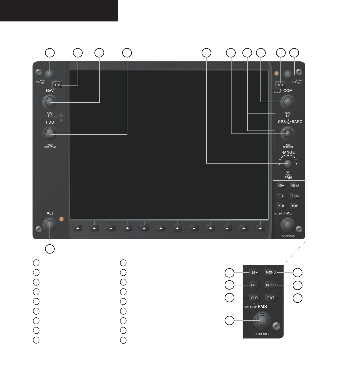
1.3 PFD/MFD CONTROLS
421 65 93
8 107
1-6
18
1
NAV VOL/ID Knob
2
NAV Frequency Transfer Key
3
NAV Knob
4
Heading Knob
5
Range Joystick
6
Course/Baro Knob
7
SD Card Slots
8
COM Knob
9
COM Frequency Transfer Key
Figure 1-3 PFD/MFD Controls
10
COM VOL/SQ Knob
11
Direct-to Key
12
Flight Plan Key
13
Clear Key
14
Flight Management System Knob
15
Menu Key
16
Procedure Key
17
Enter Key
18
Altitude Knob
11
12
13
14
15
16
17
190-00592-00 Rev. AGarmin G1000 Pilot’s Guide for the Diamond DA40
Page 19
SYSTEM OVERVIEW
The G1000 controls and keys have been designed to
simplify the operation of the system and to minimize
workload as well as the time required to access
sophisticated functionality. The following list provides an
overview of the primary function(s) of the keys and knobs
located on the display bezel.
1
NAV VOL/ID Knob – Controls the NAV audio level
Press to toggle the Morse code identifier ON and OFF.
Volume level is shown in the field as a percentage.
2
NAV Frequency Transfer Key – Transfers the
standby and active NAV frequencies
3
Dual NAV Knob – Tunes the MHz (large knob) and
kHz (small knob) standby frequencies for the NAV
receiver
Press to toggle the tuning cursor (cyan box) between
the NAV1 and NAV2 fields.
NOTE: The selected COM (displayed in green)
is controlled by the COM MIC key on the Audio
Panel.
NOTE: The Audio Panel controls are described in
the CNS & Audio Panel section.
4
HDG (Heading) Knob – Use to manually select a
heading
When this knob is pressed, a window displaying a
digital heading momentarily appears to the left of the
heading indicator and the heading bug synchronizes
with the compass lubber line.
5
Joystick – Changes the map range when rotated;
activates the map pointer when pressed
6
CRS/BARO Knob – The large knob sets the altimeter
barometric pressure and the small knob adjusts the
course. The course is only adjustable when the HSI
is in VOR1, VOR2, or OBS/SUSP mode. Pressing
this knob centers the CDI on the currently selected
VOR.
8
Dual COM Knob – Tunes the MHz (large knob) and
kHz (small knob) standby frequencies for the COM
transceiver
Pressing the knob toggles the tuning cursor (cyan box)
between the COM1 and COM2 fields.
9
COM Frequency Transfer Key – Transfers the
standby and active COM frequencies
Pressing and holding this key for two seconds auto
matically tunes the emergency frequency (121.5 MHz)
in the active frequency field.
10
COM VOL/SQ Knob – Controls COM audio level
Pressing this knob turns the COM automatic squelch
ON and OFF. Audio volume level is shown in the
field as a percentage.
11
Direct-to Key ( ) – Allows the user to enter a
destination waypoint and establish a direct course to
the selected destination (specified by identifier, chosen
from the active route, or taken from the map cursor
position)
12
FPL Key – Displays the active Flight Plan Page for
creating and editing the active flight plan or for accessing stored flight plans
190-00592-00 Rev. A Garmin G1000 Pilot’s Guide for the Diamond DA40
1-7
Page 20

SYSTEM OVERVIEW
13
CLR Key (DFLT MAP) – Erases information, cancels
an entry, or removes page menus
To immediately display the Navigation Map Page, press
and hold the CLR key (MFD only).
14
Dual FMS (Flight Management System) Knobs
– Used to select the page to be viewed (only on the
MFD)
The large knob selects a page group (MAP, WPT, AUX,
NRST) while the small knob selects a specific page
within the page group. Pressing the small knob turns
the selection cursor ON and OFF. When the cursor
is ON, data may be entered in the different windows
using a combination of the small and large knobs.
The large knob is used to move the cursor on the
page, while the small knob is used to select individual
characters for the highlighted cursor location. When
the G1000 displays a list of information that is too
long for the display screen, a scroll bar appears along
the right side of the display to indicate the availability
of additional items within the selected category. Press
the FMS/PUSH CRSR knob to activate the cursor and
turn the large knob to scroll through the list.
procedures (STARs) and approaches (IAPs) from the
database and loads them into the active flight plan.
17
ENT Key – Accepts a menu selection or data entry
This key is used to approve an operation or to com
plete data entry. It is also used to confirm selections
and information entries.
18
Dual ALT (Altitude Select) Knob – Sets the Selected
Altitude in the box above the Altimeter
The large knob selects the thousands, while the small
knob selects the hundreds.
1.4 SECURE DIGITAL CARDS
NOTE: Refer to the Appendices for instructions
on updating the aviation database.
The GDU 1040 data card slots (see 7 on Figure 1-
3) use Secure Digital (SD) cards. SD cards are used for
aviation database updates and terrain database storage.
1-8
15
MENU Key – Displays a context-sensitive list of
options
This option list allows the user to access additional
features or to make setting changes that relate to
certain pages.
16
PROC Key – Selects approaches, departures and
arrivals from the flight plan
When using a flight plan, available procedures for
the departure and/or arrival airport are automatically
suggested. If a flight plan is not used, the desired air
port and the desired procedure may be selected. This
key selects IFR departure procedures (DPs), arrival
To install an SD card:
Insert the SD card in the SD card slot located
on the right side of the display bezel (the front
of the card should be flush with the face of the
display bezel).
To remove an SD card:
Gently press on the SD card to release the
spring latch and eject the card.
190-00592-00 Rev. AGarmin G1000 Pilot’s Guide for the Diamond DA40
Page 21
SYSTEM OVERVIEW
1.5 SYSTEM POWER-UP
The G1000 System is integrated with the aircraft
electrical system and receives power directly from electrical
busses. The Garmin G1000 PFD/MFD and supporting
sub-systems include both power-on and continuous builtin test features that exercise the processor, RAM, ROM,
external inputs, and outputs to provide safe operation.
While the system begins to initialize, test annunciations
are displayed on the PFD at power-up. All system
annunciations should clear within the first minute of
power-up. The Audio Panel also annunciates all bezel
lights briefly upon power-up.
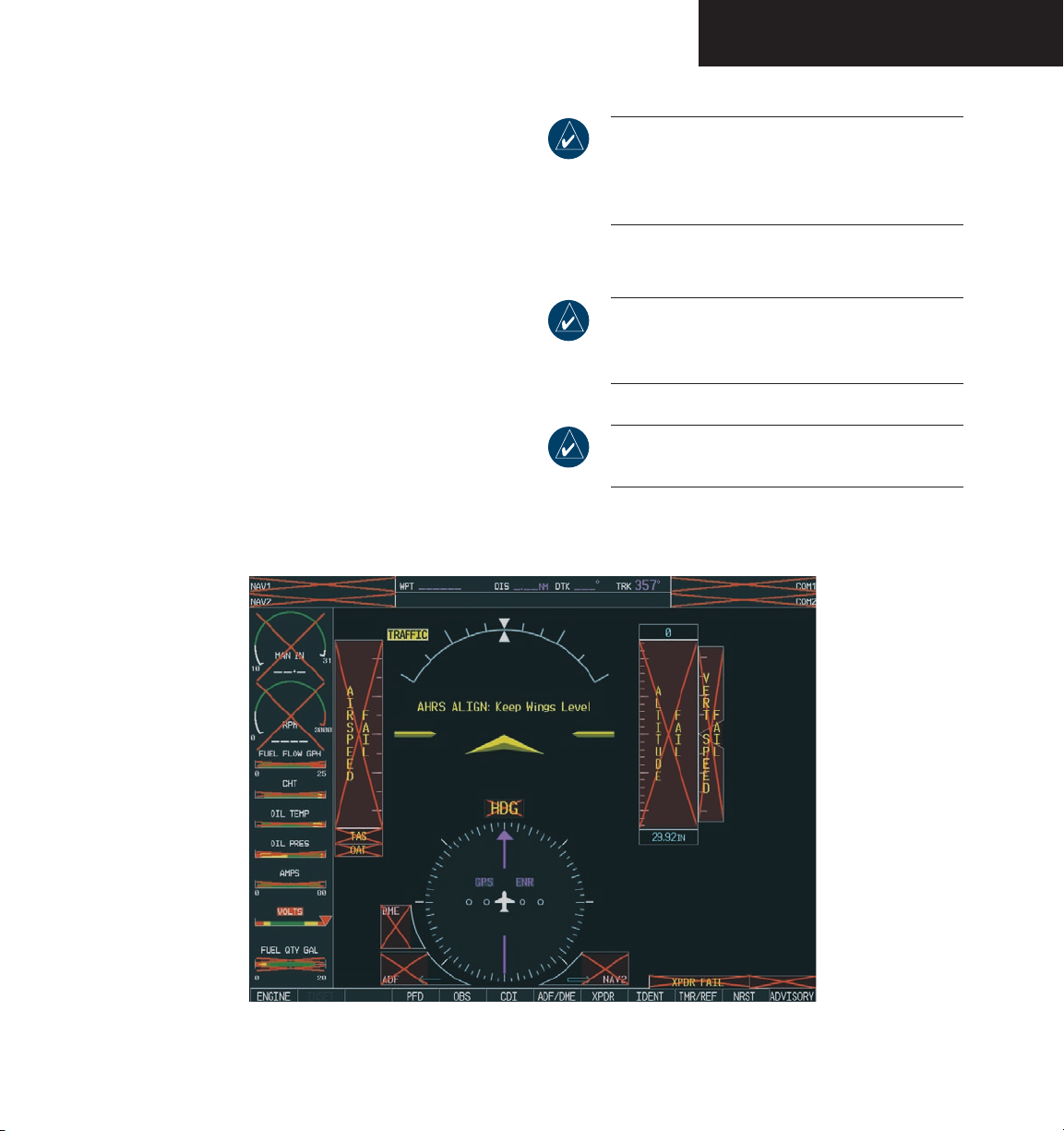
On the PFD, the AHRS system displays an ‘AHRS
ALIGN: Keep Wings Level’ message and begins to initialize.
The AHRS should display valid attitude and heading fields
within the first minute of power-up. The AHRS can align
itself while the aircraft is taxiing or during level flight.
NOTE: Refer to the approved Airplane Flight
Manual Supplement (AFMS) for specifi c
procedures concerning avionics power application
and emergency power supply operation.
NOTE: Refer to the Annunciations and Alerts
section for more information regarding system
annunciations and alerts.
NOTE: Refer to the Appendices for AHRS
initialization bank angle limitations.
Figure 1-4 PFD Initialization
190-00592-00 Rev. A Garmin G1000 Pilot’s Guide for the Diamond DA40
1-9
Page 22

SYSTEM OVERVIEW
When the MFD powers up, the MFD Power-up page
displays the following data:
• System version
• Copyright
• Checklist filename
• Land database name and version
• Obstacle database name and version
• Terrain database name and version
• Aviation database name, version, and effective
dates
When this information has been reviewed for currency
(to ensure that no databases have expired), the pilot is
prompted to continue. Current database information is
displayed with valid operating dates, cycle number and
database type.
Press the
ENT key to acknowledge this information
and proceed to the Navigation Map Page. When the
system has acquired a sufficient number of satellites to
determine a position, the Navigation Map Page appears
showing the aircraft current position.
1-10
Figure 1-5 MFD Power-up Page
190-00592-00 Rev. AGarmin G1000 Pilot’s Guide for the Diamond DA40
Page 23
SYSTEM OVERVIEW
1.6 DISPLAY BACKLIGHTING
NOTE: Refer to the Primary Flight Display section
for instructions on manually adjusting the
backlighting.
The G1000 PFD and MFD displays use photocell
technology to automatically adjust for ambient lighting
conditions. Photocell calibration curves are pre-configured
to optimize display appearance through a broad range of
cockpit lighting conditions. PFD, MFD, and Audio Panel
bezel/key lighting are normally controlled directly by the
existing instrument panel dimmer bus.
If desired, PFD and MFD display backlighting and
PFD, MFD, and Audio Panel bezel/key brightness can also
be adjusted manually. Audio Panel bezel/key brightness is
directly tied to MFD bezel/key adjustment.
1.7 SYSTEM OPERATION
NORMAL OPERATION
The PFD and MFD are connected together on a single
Ethernet bus, allowing for high-speed communication
between the two units. Each IAU is connected to a single
display, as shown in Figure 1-1. This allows the units to
share information, enabling true system integration.
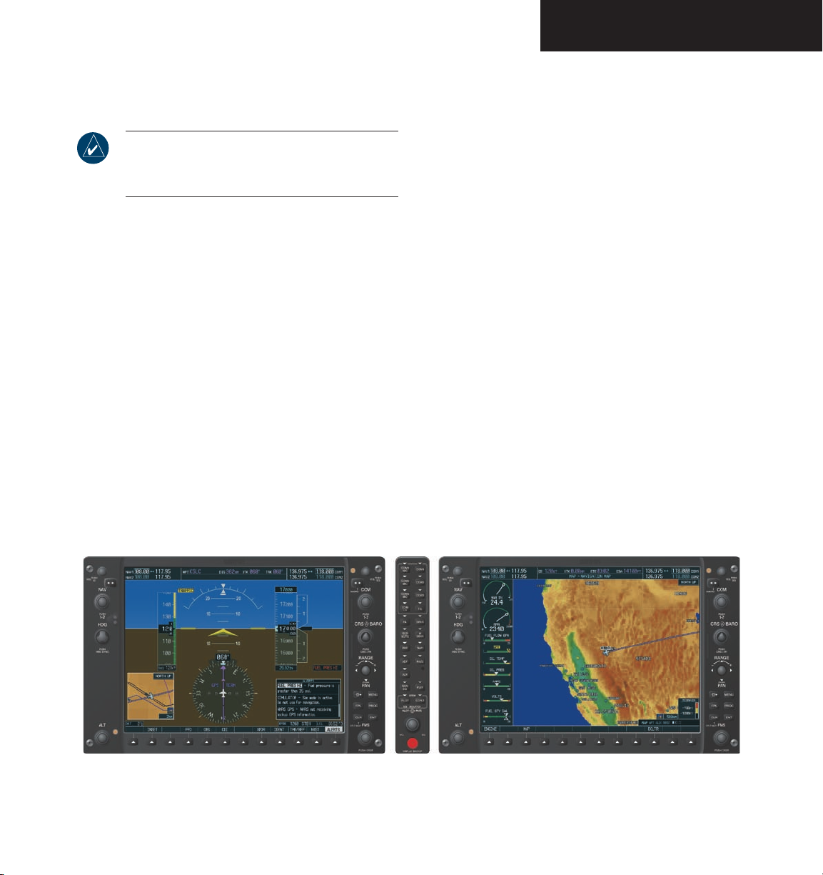
In normal operating mode, the PFD displays
graphical flight instrumentation in lieu of traditional gyro
instruments. Attitude, heading, airspeed, altitude, and
vertical speed are all shown on one display (refer to the
PFD section for more information). The MFD shows a
full-color moving map with navigation information (refer
to the MFD section for a complete discussion of MFD
operation). Both displays offer control of COM and NAV
frequency selection, as well as heading, course/baro, and
altitude select functions. On the left of the MFD display,
the Engine Indication System (EIS) cluster shows engine
and airframe instrumentation (see the EIS section). The
following figure shows an example of normal G1000
System operation.
Figure 1-6 G1000 Normal Operation
190-00592-00 Rev. A Garmin G1000 Pilot’s Guide for the Diamond DA40
1-11
Page 24
SYSTEM OVERVIEW
REVERSIONARY MODE
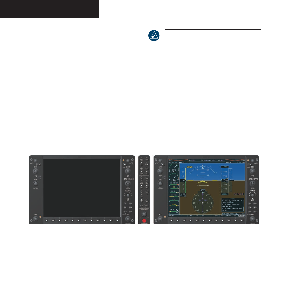
Should a failure occur in either display, the G1000
automatically enters reversionary mode. In reversionary
mode, all important flight information is shown on the
remaining display. Figure 1-7 shows an example of G1000
reversionary mode where the PFD has failed.
NOTE: The system alerts the pilot when backup
paths are utilized by the LRUs. Refer to the
Annunciations and Alerts section for further
information regarding these and other system
alerts.
If a display fails, the appropriate GIA 63-GDU 1040
Ethernet interface is cut off. Thus, the IAU can no longer
communicate with the remaining display (refer to Figure
1-1), and the NAV and COM functions provided to the
failed display by the IAU are flagged as invalid on the
remaining display. The system reverts to backup paths for
the AHRS, ADC, Engine/Airframe Unit, and transponder,
as required. The change to backup paths is completely
automated for all LRUs and no pilot action is required.
If the system fails to detect a display problem,
reversionary mode may be manually activated by pressing
the Audio Panel’s red DISPLAY BACKUP button.
Pressing this button again deactivates reversionary mode.
1-12
Figure 1-7 G1000 Reversionary Mode (Failed PFD)
190-00592-00 Rev. AGarmin G1000 Pilot’s Guide for the Diamond DA40
Page 25
SYSTEM OVERVIEW
Attitude/Heading Invalid
available
unavailable
AHRS
no-GPS
Mode
AHRS Normal
Operation
Airspeed Data
available
unavailable
AHRS no-Mag
Mode
AHRS no-Mag/
no-Air Mode
Heading Invalid
available
unavailable
available
unavailable
available
unavailable
GPS
Magnetometer
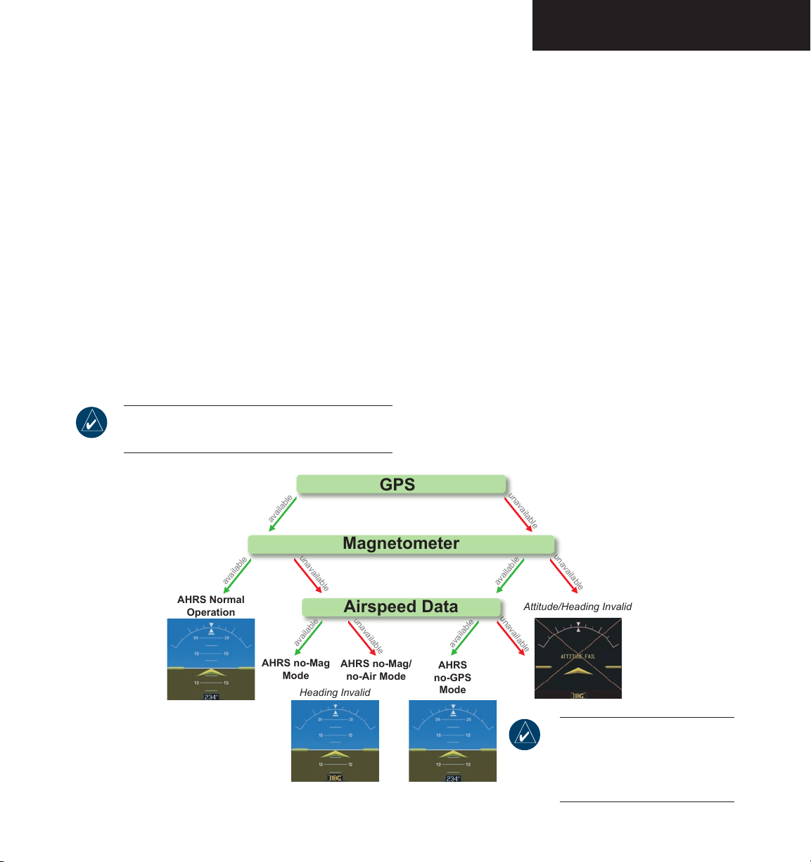
AHRS MODES OF OPERATION
The GRS 77 Attitude and Heading Reference
System (AHRS) performs attitude, heading, and
vertical acceleration calculations for the G1000 System
utilizing GPS, Magnetometer, and air data in addition
to information from its internal sensors. Attitude and
heading information are updated on the PFD while the
AHRS receives appropriate combinations of information
from the external sensor inputs (see Figure 1-8).
Loss of GPS, Magnetometer, or air data inputs is
communicated to the pilot by message advisory alerts.
Any failure of the internal AHRS inertial sensors results
in loss of attitude and heading information (as indicated
by red ‘X” flags over the corresponding flight instruments
on the PFD).
NOTE: Refer to the Annunciations and Alerts
section for specific AHRS alert information.
GPS Input Failure
Two GPS inputs are provided to the AHRS. If GPS
information from one of the inputs fails, the AHRS uses
the remaining GPS input and an alert message is issued to
inform the pilot. If both GPS inputs fail, the AHRS can
continue to provide attitude and heading information to
the PFD as long as Magnetometer and airspeed data are
available and valid.
Magnetometer Failure
If the Magnetometer input fails, the AHRS continues to
output valid attitude information; however, the heading
output on the PFD is flagged as invalid with a red ‘X’.
Air Data Input Failure
Failure of the air data input has no effect on the AHRS
output while AHRS is receiving valid GPS information.
Invalid/unavailable airspeed data in addition to GPS failure
results in loss of all attitude and heading information.
Figure 1-8 AHRS Operation
190-00592-00 Rev. A Garmin G1000 Pilot’s Guide for the Diamond DA40
NOTE: Aggressive maneuvering
while AHRS is not operating
normally may degrade AHRS
accuracy.
1-13
Page 26
SYSTEM OVERVIEW
1.8 CHECKLISTS (OPTIONAL)
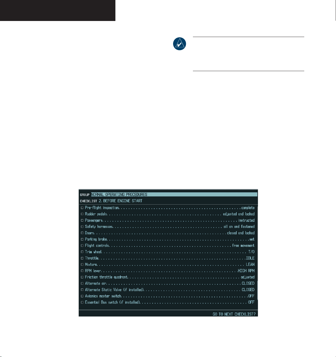
The G1000 MFD is able to display electronic checklists
customized for the Diamond DA40. The G1000 accesses
the checklists from an SD card inserted into the bezel slot
(see Figure 1-3). Pressing the CHKLIST softkey allows
access to all checklists. Pressing the EXIT softkey exits
the Checklist pages and displays the page last viewed.
If the SD card contains a valid checklist file, the Powerup Page displays both the aircraft make and model to
which the checklist applies (DA40, DIAMOND AIRCRAFT
INDUSTRIES) and copyright information.
If the SD card contains an invalid checklist file or
no checklist, the Checklist Page displays ‘INVALID
CHECKLIST’ or ‘CHECKLIST NOT PRESENT’.
NOTE: Checklists cannot be edited from within the
system. Refer to the Garmin Aviation Checklist
Editor (ACE) User’s Guide for information on
creating and editing checklists.
The Checklist Page displays the following data:
• Selected checklist group
• Selected checklist title
• Selected checklist text, including:
– Plain text
– Notes
– Cautions
– Warnings
– Challenge/Response pairs
– Challenges with no responses
– Check state of each checkable item
– Checklist complete indicator
1-14
Figure 1-9 Sample Checklist
190-00592-00 Rev. AGarmin G1000 Pilot’s Guide for the Diamond DA40
Page 27

TM
G1000
Primary Flight Display
Page 28

Garmin G1000 Pilot’s Guide for the Diamond DA40 190-00592-00 Rev. A
Page 29

PRIMARY FLIGHT DISPLAY
2.1 INTRODUCTION
WARNING: In the event that the airspeed, attitude,
altitude, or heading indications become unusable,
please refer to the backup instruments.
This section describes the major features of the G1000
Primary Flight Display (PFD) as installed on Diamond
DA40, DA40F, and DA40D aircraft. Information is displayed using the G1000’s two 10.4-inch color flat-panel
displays. During normal operation, the left display is configured as a Primary Flight Display.
The PFD provides increased situational awareness by
replacing the traditional “six-pack” of instruments on the
pilot’s panel with an easy-to-scan display that provides
a large horizon and airspeed, attitude, altitude, vertical
speed, navigation, communication, annunciation, terrain,
traffic, and lightning (optional) information. The PFD
also controls the operation of the transponder, the selec
tion of NAV/COM frequencies, audio volume, and many
navigation features. The operation of these features is explained in other supporting sections.
The G1000 system controls were designed so that, re
gardless of which seat the pilot is flying from, the aircraft
can be flown with one hand and the controls manipulated
with the other hand.
-
-
The PFD displays the following:
• Flight Instruments (2.4)
– Airspeed Indicator with True Airspeed Box
– Attitude and Slip/Skid Indicators
– Altimeter with Selected Altitude and Barometric
Setting Boxes
– Vertical Deviation/Glideslope Indicator
– Marker Beacon Annunciations
– Vertical Speed Indicator
– Horizontal Situation Indicator
- Turn Rate Indicator
- Bearing Pointers and Information Windows
- DME Information Window
- Radio Tuning Window (ADF/DME)
- Navigation Source
• Communication, Navigation, and Surveillance
(CNS) Information (2.5)
– Communication (COM) Frequency Window
– Navigation (NAV) Frequency Window
– Navigation Status Bar
– Transponder Status Bar
• Supplemental Flight Data (2.6)
– Outside Air Temperature Box
– System Time Box
– Inset Map
– Auxiliary Windows
- Timer/References Window
- Nearest Airports Window
- Direct-to Window
- Flight Plan Window
- Procedures Window
• Alerts and Annunciations (2.8)
– Alerts Window
– Annunciation Window
– Terrain Awareness and Warning System (TAWS)
Alert Annunciations
– Traffic Annunciation
Garmin G1000 Pilot’s Guide for the Diamond DA40190-00592-00 Rev. A
2-1
Page 30
PRIMARY FLIGHT DISPLAY
1
2
3
4
5
6
18
17
16
7
15
14
13
12
11
10
9
8
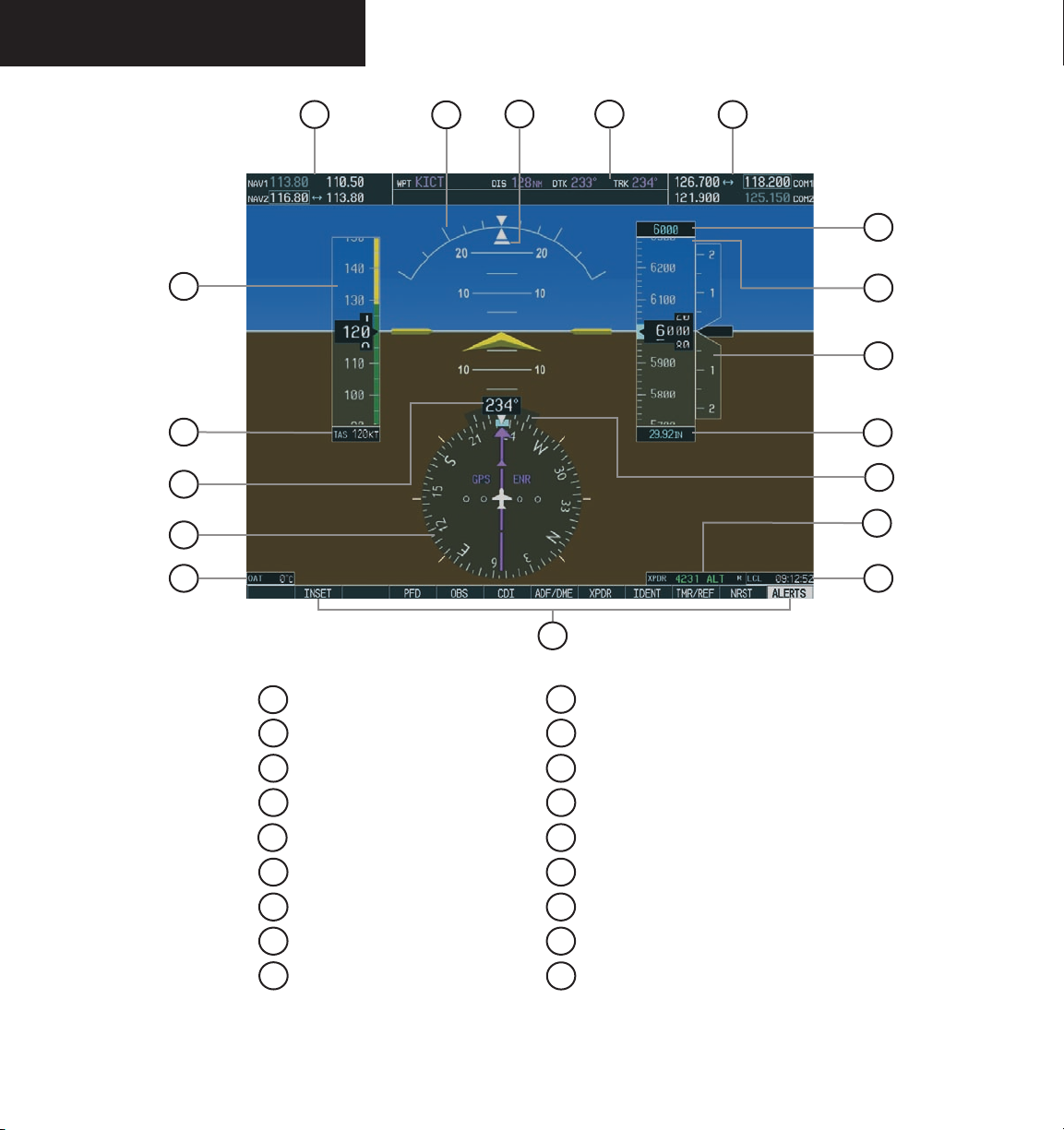
1
NAV Frequency Window
2
Airspeed Indicator
3
True Airspeed Box
4
Heading Box
5
Horizontal Situation Indicator
6
Outside Air Temperature Box
7
Softkeys
8
System Time Box
9
Transponder Status Bar
Figure 2-1 Default PFD Information
Garmin G1000 Pilot’s Guide for the Diamond DA40 190-00592-00 Rev. A2-2
10
Turn Rate Indicator
11
Barometric Setting Box
12
Vertical Speed Indicator
13
Altimeter
14
Altitude Reference Box
15
COM Frequency Window
16
Navigation Status Bar
17
Slip/Skid Indicator
18
Attitude Indicator
Page 31
PRIMARY FLIGHT DISPLAY
12
1
11
10
9
2
3
4
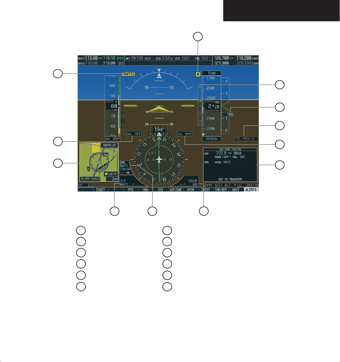
1
Traffic Annunciation
2
Selected Heading Box
3
Inset Map
4
BRG1 Information Window
5
DME Information Window
6
BRG2 Information Window
Figure 2-2 Additional PFD Information
5
7
Auxiliary Window (Radio Tuning Window)
8
Selected Course Box
9
Annunciation Window
10
Vertical Speed Pointer
11
Vertical Deviation/Glideslope Indicator
12
Marker Beacon Annunciation
6
8
7
Garmin G1000 Pilot’s Guide for the Diamond DA40190-00592-00 Rev. A
2-3
Page 32
PRIMARY FLIGHT DISPLAY
2.2 BACKLIGHTING
NOTE: The backlighting can only be adjusted
from the PFD, except in reversionary mode.
NOTE: No other window can be displayed in the
lower right corner of the PFD when the MENU
key is pressed to change the backlighting.
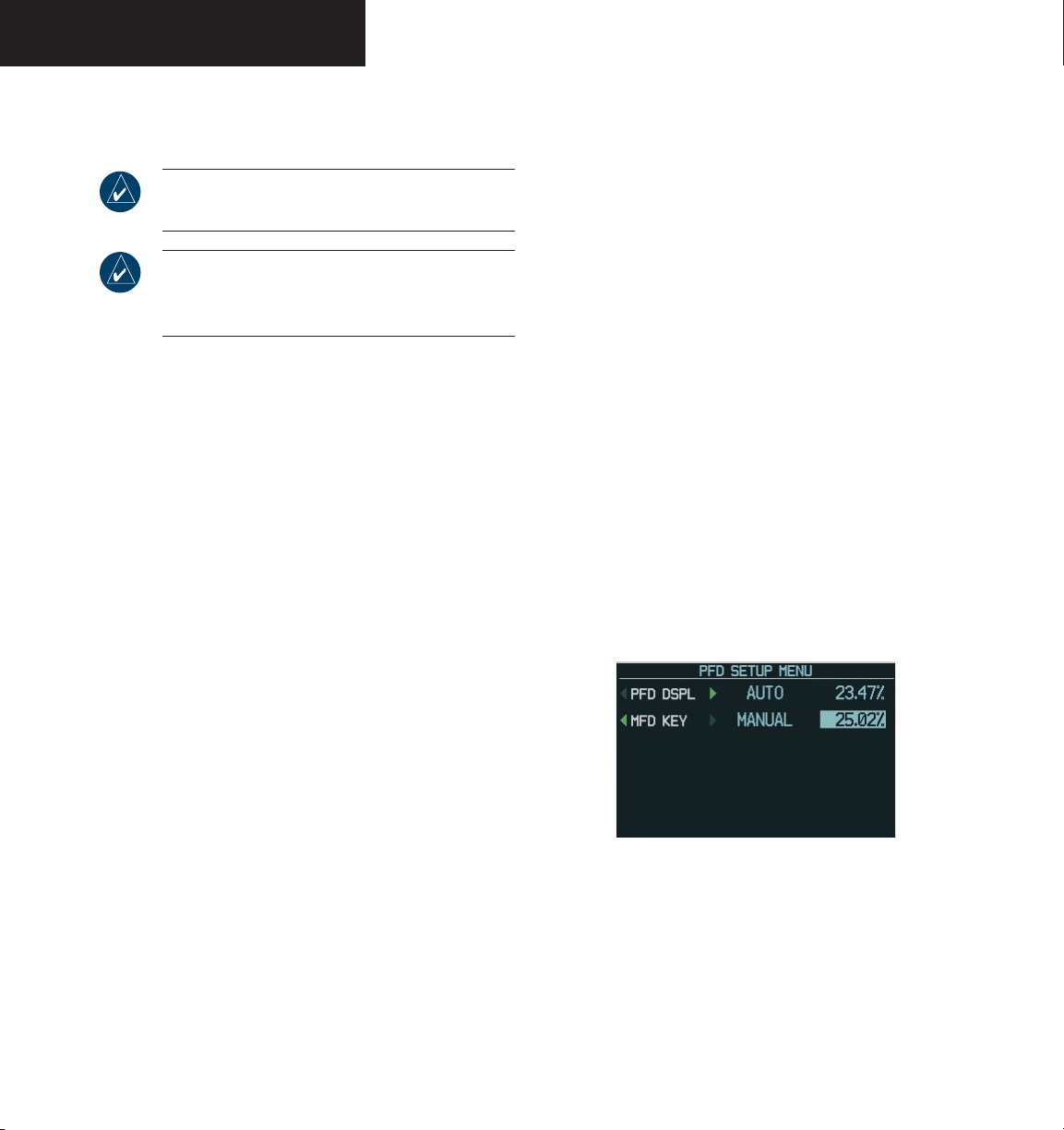
The backlighting of both the display and the keys can
be adjusted for the PFD and MFD. The backlighting intensity ranges from 0.14% to 100.00%. Two modes exist
for adjustment:
• Auto (default) – The G1000 adjusts the backlighting automatically with reference to the amount of
light in the cockpit
• Manual – Allows the pilot to manually adjust the
backlighting
To manually adjust the backlighting for the
PFD and MFD:
To manually adjust the backlighting for the
PFD and MFD keys:
MENU
1. Press the
the PFD Setup Menu Window. ‘AUTO’ is now
highlighted next to ‘PFD DSPL’.
2. Turn the
DSPL’. Turn the
of the green arrowhead to display ‘PFD KEY’.
3. Turn the
Turn the
tion window. Turn the
‘MANUAL’, then press the
4. With the intensity value now highlighted,
turn the
backlighting, then press the
5. Turn the
DSPL’ and turn the
tion of the green arrowhead to display ‘MFD
KEY’. Repeat steps 3 and 4. Press the
MENU
large FMS
small FMS
small FMS
key to remove the window.
key on the PFD to display
large FMS
large FMS
knob to highlight ‘PFD
small FMS
knob in the direction
knob to highlight ‘AUTO’.
knob to display the selec-
FMS
knob to select
ENT
knob to select the desired
ENT
knob to highlight ‘MFD
small FMS
knob in the direc-
key.
key.
CLR
or
MENU
1. Press the
the PFD Setup Menu window. ‘AUTO’ is now
highlighted next to ‘PFD DSPL’.
CLR
or
small FMS
small FMS
2. Turn the
tion window. Turn the
‘MANUAL’, then press the
3. With the intensity value now highlighted,
turn the
backlighting, then press the
Turn the large FMS knob to highlight ‘AUTO’ next
4.
to ‘MFD DSPL’ and repeat steps 2 and 3. Press
the
key on the PFD to display
knob to display the selec-
FMS
knob to select
ENT
key.
knob to select the desired
ENT
MENU
key to remove the window.
Garmin G1000 Pilot’s Guide for the Diamond DA40 190-00592-00 Rev. A2-4
key.
Figure 2-3 PFD Setup Menu Window
Page 33

PRIMARY FLIGHT DISPLAY
2.3 SOFTKEY FUNCTION
When a softkey is turned on, its color changes to black
text on gray background and remains this way until it is
turned off, at which time it reverts to white text on black
background. The
NRST, and ALERTS
black text on gray background and automatically switch
back to white text on black background.
The PFD softkeys listed provide control over flight
management functions, including GPS, NAV, terrain, traf
fic, and weather (optional).
• INSET – Displays Inset Map in PFD lower left
corner
OFF
DCLTR
TRAFFIC
TOPO
TERRAIN
STRMSCP
CDI, IDENT, ADF/DME, TMR/REF,
softkeys change momentarily to
OffOn
Figure 2-4 Softkey Operation
-
– Removes Inset Map
(3) – Selects desired amount of map detail;
declutter level appears in the DCLTR softkey:
NO DECLUTTER
DECLUTTER – 1
DECLUTTER – 2
data
DECLUTTER – 3
remaining (removes everything except the
active flight plan)
– Displays traffic on Inset Map
– Displays topographical data (e.g., coastlines, terrain, rivers, lakes) and elevation scale
on Inset Map
– Displays terrain information on Inset
Map
(optional) – Displays lightning data
on Inset Map (within 200-nm radius of
aircraft)
: All map features visible
: Declutters land data
: Declutters land and SUA
: Declutters large NAV data
NEXRAD
XM LTNG
BACK
• PFD
tional PFD configurations
METRIC
DFLTS
DME
BRG1
360 HSI
ARC HSI
BRG2
STD BARO
BACK
(optional) – Displays NEXRAD weather
and coverage information.
(optional)
information
– Returns to previous level softkeys
– Displays second-level softkeys for addi-
– Displays current and reference
altitudes in meters, in addition to feet; also
changes barometric setting to hectopascals
from inches of mercury (in Hg)
– Resets PFD to default settings
(optional) – Displays DME Information
Window which shows actual DME distance
(Bearing 1) – Cycles through the following information in the BRG1 Information
Window:
NAV1
– Displays NAV1 waypoint frequency
or identifier and GPS-derived distance
GPS
– Displays GPS waypoint identifier and
GPS-derived distance
ADF
– Displays ADF waypoint frequency
OFF
– Removes BRG1 Information Window
– Displays 360° compass rose HSI
– Displays 140° viewable arc HSI
(Bearing 2) – Cycles through the following information in the BRG2 Information
Window:
NAV2
– Displays NAV2 waypoint frequency
or identifier and GPS-derived distance
GPS
– Displays GPS waypoint identifier and
GPS-derived distance
ADF
– Displays ADF waypoint frequency
OFF
– Removes BRG2 Information Window
– Sets barometric pressure to 29.92
in Hg (1013 hPa if METRIC softkey is
pressed)
– Returns to previous level softkeys
–
Displays XM lightning
Garmin G1000 Pilot’s Guide for the Diamond DA40190-00592-00 Rev. A
2-5
Page 34

PRIMARY FLIGHT DISPLAY
• CDI – Changes navigation mode on the CDI to
GPS, NAV1, or NAV2
• ADF/DME
or ADF/DME depending on the installation)
– Displays ADF/DME Radio Tuning Window
• OBS – Selects OBS mode on the CDI when navigating by GPS (only available with active leg)
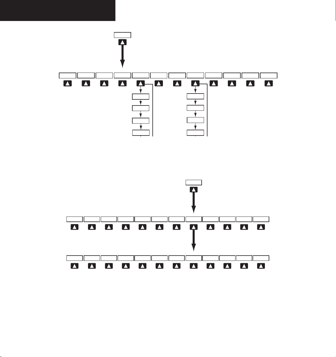
• XPDR – Displays transponder mode selection
softkeys:
STBY
ON
ALT
VFR
CODE
IDENT
BACK
(optional; may appear as ADF, DME,
– Selects standby mode (transponder does
not reply to any interrogations
– Selects Mode A (transponder replies to
interrogations)
– Selects Mode C - altitude reporting mode
(transponder replies to identification and
altitude interrogations)
– Automatically enters the VFR code (1200
in the U.S.A. only)
– Displays transponder code selection
softkeys 0-7
0 through 7
IDENT
identification to Air Traffic Control (ATC)
BKSP
BACK
– Provides special aircraft position identi-
fication to ATC
– Returns to previous level softkeys
– Use numbers to enter code
– Provides special aircraft position
– Removes numbers entered one by one
– Returns to previous level softkeys
• IDENT – Provides special aircraft position identification to ATC
• TMR/REF – Displays Timer/References Window
• NRST – Displays Nearest Airports Window
• ALERTS – Displays Alerts Window
Garmin G1000 Pilot’s Guide for the Diamond DA40 190-00592-00 Rev. A2-6
Page 35
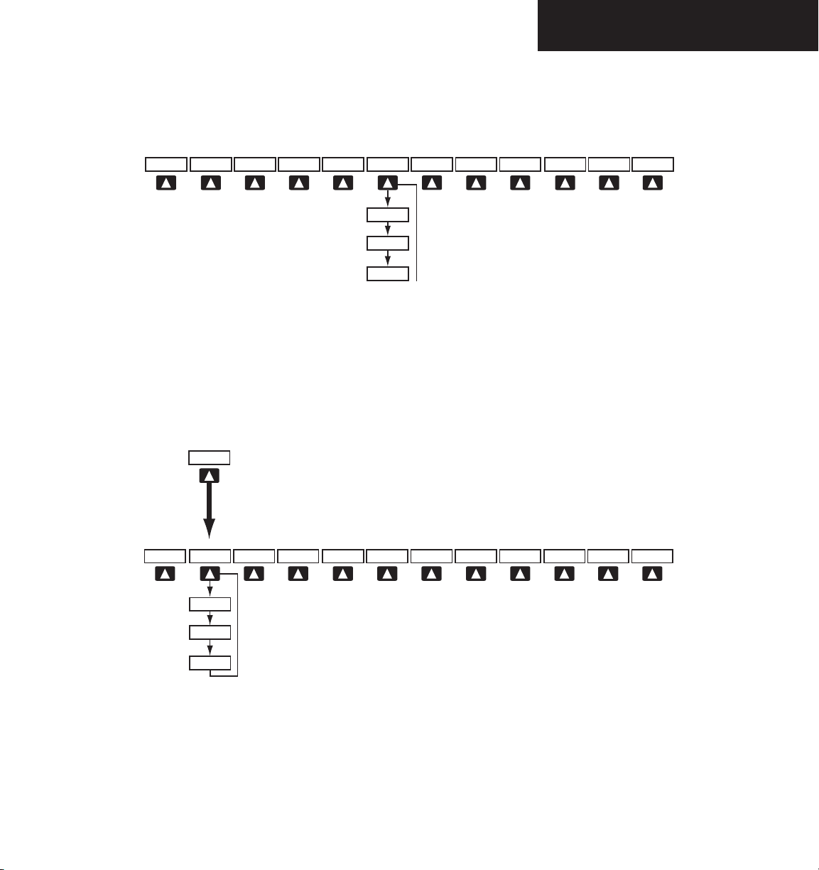
Figure 2-5 Top-Level PFD Softkeys
()
()
()
PRIMARY FLIGHT DISPLAY
Garmin G1000 Pilot’s Guide for the Diamond DA40190-00592-00 Rev. A
Figure 2-6 INSET Softkeys
2-7
Page 36
PRIMARY FLIGHT DISPLAY
Figure 2-7 PFD Configuration Softkeys
Figure 2-8 XPDR Softkeys
Garmin G1000 Pilot’s Guide for the Diamond DA40 190-00592-00 Rev. A2-8
Page 37

PRIMARY FLIGHT DISPLAY
2.4 FLIGHT INSTRUMENTS
AIRSPEED INDICATOR
The Airspeed indicator displays airspeed on a rolling
number gauge, using a moving tape. The following infor
mation is also displayed:
• Speed indication
• Speed ranges
• Airspeed Trend Vector
• Vspeed References
Speed Indication
The numeric labels and major tick marks on the moving tape are marked at intervals of 10 knots, while minor
tick marks on the moving tape are indicated at intervals
of 5 knots. Speed indication starts at 20 knots, with 60
knots of airspeed viewable at any time. The actual air
speed is displayed inside the black pointer. The pointer
remains black until reaching never-exceed speed (V
which point it turns red.
NE
-
-
), at
Vspeed References
Vspeeds are set using the TMR/REF softkey. Glide, VR,
VX, and VY are shown on the References window. When
active (ON), the Vspeeds are displayed at their respective
locations to the right of the airspeed scale (refer to the
Auxiliary Windows portion of this Flight Instruments sec
-
tion to set and display Vspeeds).
True Airspeed Box
The True Airspeed box is located below the Airspeed
indicator and displays the true airspeed in knots.
Airspeed Trend
Vector
Actual Airspeed
Vspeed
References
Speed Ranges
A color-coded (white, green, yellow, and red) speed
range strip is located on the moving tape. The colors de
note flaps operating range, normal operating range, cau
tion range, and never-exceed speed (V
). A red range is
NE
-
-
also present for low speed awareness. Refer to the Aircraft
Flight Manual Supplement (AFMS) for speed criteria.
Airspeed Trend Vector
The Airspeed Trend Vector is a vertical, magenta line
extending up or down on the airspeed scale, located right
of the color-coded speed range strip. The end of the
trend vector displays approximately what airspeed will be
reached in six seconds if the current rate of acceleration or
deceleration is maintained. The trend vector is absent if
the speed remains constant or if any data needed to calcu
late airspeed is not available due to a system failure.
Garmin G1000 Pilot’s Guide for the Diamond DA40190-00592-00 Rev. A
-
True Airspeed
Box
Figure 2-9 Airspeed Indicator
Figure 2-10 Red Pointer at V
Speed Ranges
NE
2-9
Page 38
PRIMARY FLIGHT DISPLAY
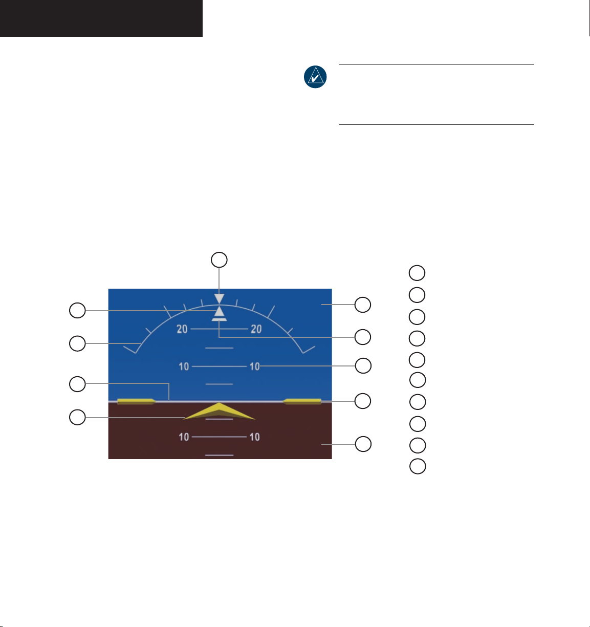
ATTITUDE INDICATOR
The attitude information is displayed over a virtual blue
sky and a brown ground with a white horizon line. The
Attitude indicator displays the following information:
• Pitch indication
• Roll indication
• Slip/Skid indication
10
1
NOTE: Supplemental flight data, such as the Inset
Map and the Alerts and Annunciation Windows,
disappear from the PFD when pitch exceeds +30˚
or -20˚ or when a 65˚ bank angle is reached.
1
Roll Pointer
2
9
Roll Scale
3
Horizon Line
2
3
4
Figure 2-11 Attitude Indicator
Garmin G1000 Pilot’s Guide for the Diamond DA40 190-00592-00 Rev. A2-10
8
7
6
5
4
Aircraft Symbol
5
Land Representation
6
Aircraft Wing Tips
7
Pitch Scale
8
Slip/Skid Indicator
9
Sky Representation
10
Roll Scale Zero
Page 39
PRIMARY FLIGHT DISPLAY
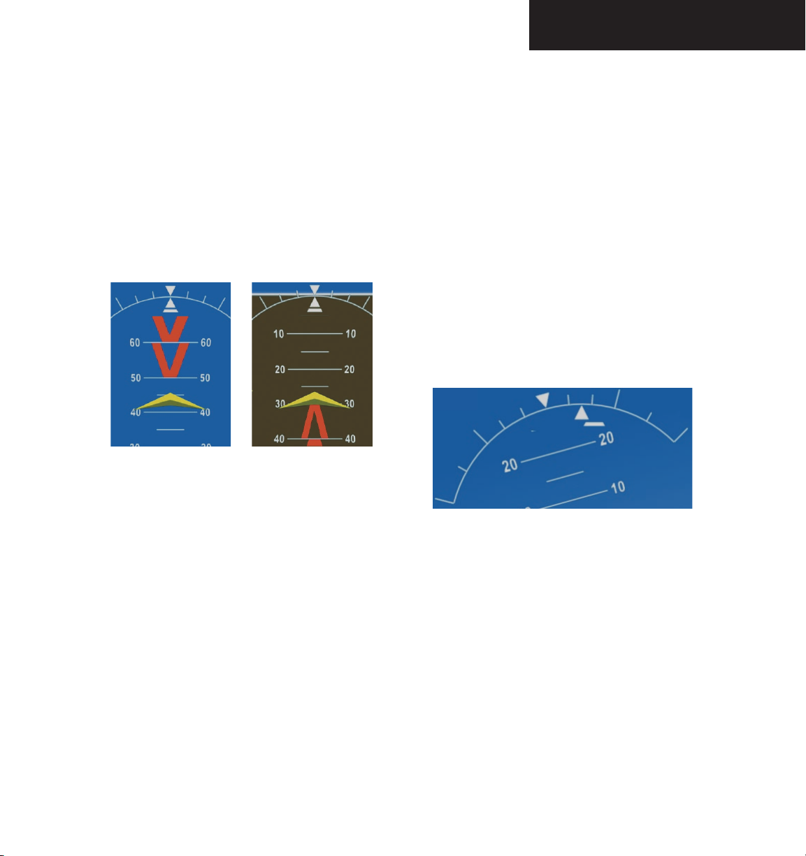
Pitch Indication
Major pitch marks and numeric labels at 10, 20, 30,
40, 50, 60, 70 and 80 degrees are shown above and below the horizon line. Minor pitch marks at 5, 15 and 25
degrees above the horizon line and 5, 15, 25, 35 and 45
degrees below the horizon line are shown. The horizon
line is part of the pitch scale. Red extreme pitch warning
chevrons pointing toward the horizon are displayed starting at 50 degrees above and 30 degrees below the horizon
line (refer to the figures on the next page).
Nose LowNose High
Roll Indication
Major tick marks at 30 and 60 degrees and minor tick
marks at 10, 20 and 45 degrees are shown to the left and
right on the roll scale. The inverted white triangle indicates 0 on the roll scale. Angle of bank is indicated by the
position of the roll pointer on the roll scale.
Slip/Skid Indication
The Slip/Skid indicator resides beneath the roll pointer.
The indicator moves with the roll pointer and moves laterally away from the pointer to indicate lateral acceleration.
A slip/skid is indicated by the location of the Slip/Skid
indicator relative to the roll pointer. One Slip/Skid indicator displacement is equal to one ball displacement when
compared to a traditional Slip/Skid indicator.
Figure 2-12 Pitch Attitude Warnings
Garmin G1000 Pilot’s Guide for the Diamond DA40190-00592-00 Rev. A
Figure 2-13 Roll and Slip/Skid Indication
2-11
Page 40
PRIMARY FLIGHT DISPLAY
ALTIMETER
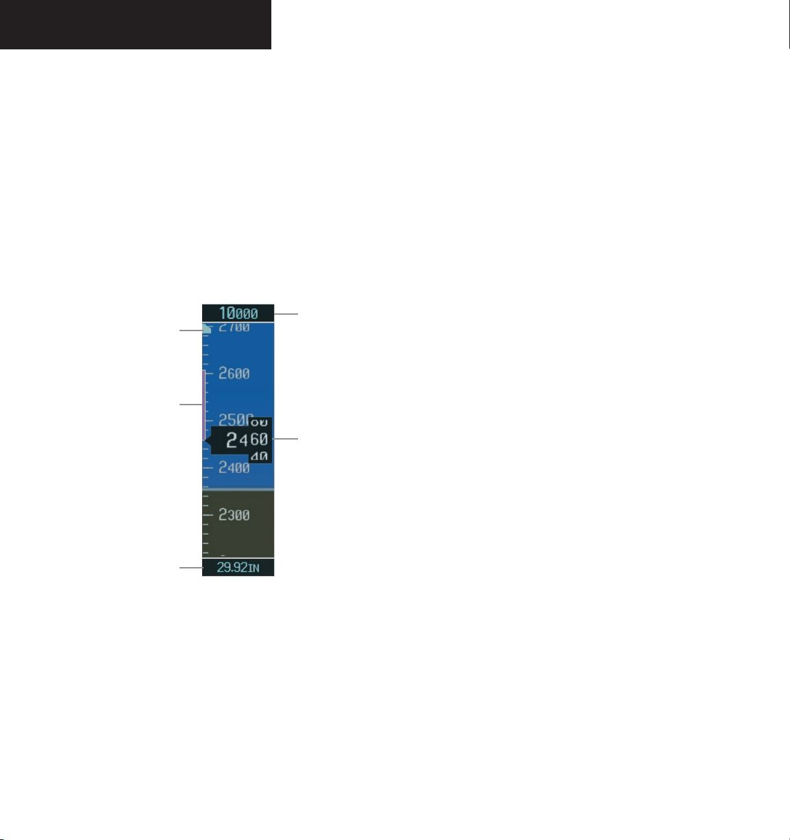
The Altimeter displays barometric altitude values in
feet on a rolling number gauge using a moving tape. The
Altimeter displays the following information:
• Altitude values
• Altitude Select Bug
• Altitude Trend Vector
• Selected Altitude box
• Barometric Setting Box
• Altitude Alerting function
Selected Altitude
Altitude Select Bug
Altitude Trend
Vector
Box
Current Altitude
Altitude Select Bug
The Altitude Select Bug is displayed at the Selected
Altitude or the edge of the tape (whichever is closer to
the current altitude) to provide increased altitude aware
ness. This altitude also appears in the Selected Altitude
Box above the Altimeter.
To set the Selected Altitude bug:
ALT
Turn the
bug. The
the
large ALT
knobs to set the Selected Altitude
small ALT
knob sets the hundreds and
knob sets the thousands.
Altitude Trend Vector
The vertical, magenta line extends up or down the altitude scale located left of the numeric labels. The end
of the trend vector displays approximately what altitude
will be reached in six seconds if the current rate of vertical
speed is maintained. The trend vector is absent if altitude
remains constant or if any data needed to calculate it is not
available due to a system failure.
Selected Altitude Box
The Selected Altitude box is located above the Altimeter and displays, in feet, the altitude selected by turning
the ALT knobs. The metric value, when selected, is displayed on top of the Selected Altitude box.
Barometric Setting
Box
Figure 2-14 Altimeter
Altitude Values
The numeric labels and major tick marks are shown
at intervals of 100 feet. Minor tick marks are at intervals
of 20 feet. The current altitude is displayed in the black
pointer.
Garmin G1000 Pilot’s Guide for the Diamond DA40 190-00592-00 Rev. A2-12
Barometric Setting Box
The Barometric Setting Box displays the barometric
pressure in inches of mercury (in Hg) or hectopascals
(hPa).
To select barometric pressure:
Turn the large BAR
the desired setting.
O (outer) knob to select
Page 41
PRIMARY FLIGHT DISPLAY
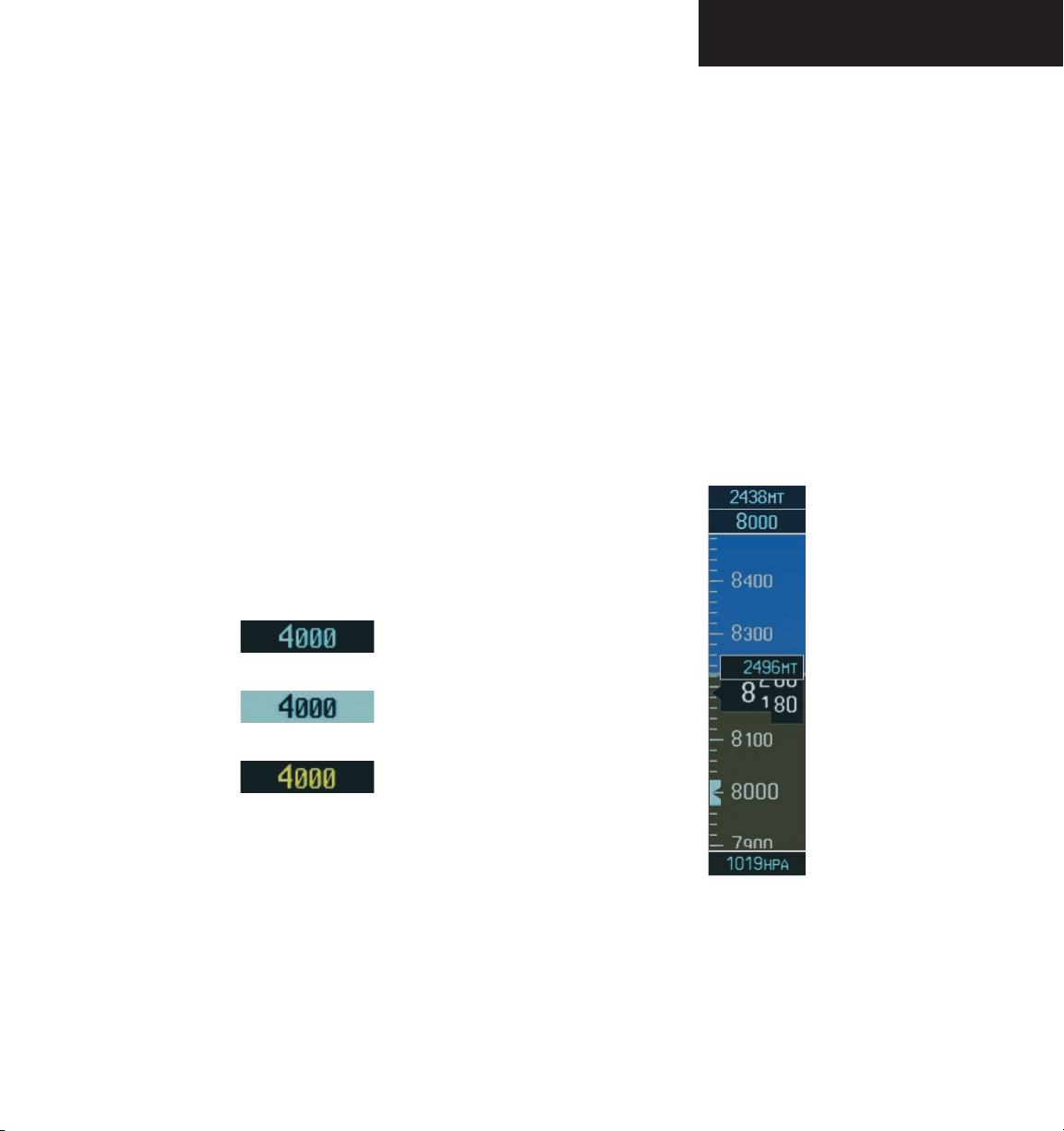
Altitude Alerting
The altitude Alerting function provides the pilot with a
visual alert when approaching the Selected Altitude. This
function is independent of the flight control system. Visual annunciations appear in the Selected Altitude box. The
Altitude Alerting function is reset whenever the Selected
Altitude is adjusted.
The Selected Altitude Box flashes for five seconds, re
versing color to black text on a cyan background when
the aircraft reaches 1000 feet from the Selected Altitude.
At 200 feet from the Selected Altitude, color reversal to
normal occurs along with an aural tone.
After capturing the Selected Altitude, the Altitude
Alerting feature alerts the pilot whenever deviations of
±200 ft from the Selected Altitude occur. The Selected
Altitude Box flashes yellow text on a black background for
five seconds to indicate the deviation.
Within 1000 ft
-
Metric Display
Selected and current altitude can be displayed in meters in addition to English units. The barometric pressure
may also be displayed in hectopascals.
To display altitude in meters and barometric
pressure in hectopascals:
1. Press the
level softkeys.
2. Press the METRIC softkey to display altitude in
meters and barometric pressure in hectopascals.
Press the
softkeys.
PFD softkey to display the second
BACK
softkey to return to the top level
Within 200 ft
Deviation of ±200 ft
Figure 2-15 Altitude Alerting Visual Annunciations
Garmin G1000 Pilot’s Guide for the Diamond DA40190-00592-00 Rev. A
Figure 2-16 Altimeter (Metric)
2-13
Page 42
PRIMARY FLIGHT DISPLAY
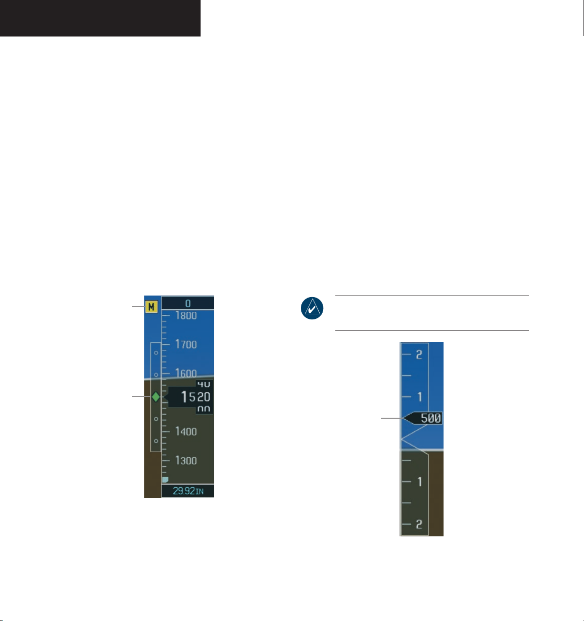
VERTICAL DEVIATION/GLIDESLOPE
INDICATOR
The Vertical Deviation/Glideslope indicator is a window on the left side of the Altimeter. The window appears
when an ILS is tuned in the active NAV field (and selected
on the Audio Panel). A green diamond appears and acts
as the vertical deviation indication, just like a glideslope
needle on a conventional indicator.
MARKER BEACON ANNUNCIATIONS
Marker Beacon Annunciations are displayed on the
PFD to the left of the Selected Altitude Box. Outer marker
reception is indicated by a blue light, middle by amber,
and inner by white (refer to the Audio Panel section for
more information).
Marker Beacon
Annunciation
VERTICAL SPEED INDICATOR
The Vertical Speed Indicator displays the aircraft vertical speed with numeric labels and tick marks at 1,000 ft
and 2,000 ft in each direction on the non-moving tape.
Minor tick marks are at intervals of 500 ft.
Vertical Speed Pointer
The Vertical Speed pointer displays the current vertical
speed and points to that speed on the non-moving tape.
If the rate of ascent is greater than 2,000 feet per minute,
the pointer appears at the top edge of the non-moving
tape and the number of feet per minute appears inside
the pointer. If the rate of descent is greater than 2,000
feet per minute, a negative sign is displayed in the pointer
(-2,000) for negative (down) vertical speed and the point
er appears at the bottom edge of the non-moving tape.
NOTE: Digits appear in the pointer when the
climb or descent rate is greater than 100 fpm.
-
Vertical
Deviation/Glideslope
Indicator
Figure 2-17 Marker Beacon and Vertical Deviation
Garmin G1000 Pilot’s Guide for the Diamond DA40 190-00592-00 Rev. A2-14
Vertical Speed
Pointer
Figure 2-18 Vertical Speed Indicator
Page 43
HORIZONTAL SITUATION INDICATOR
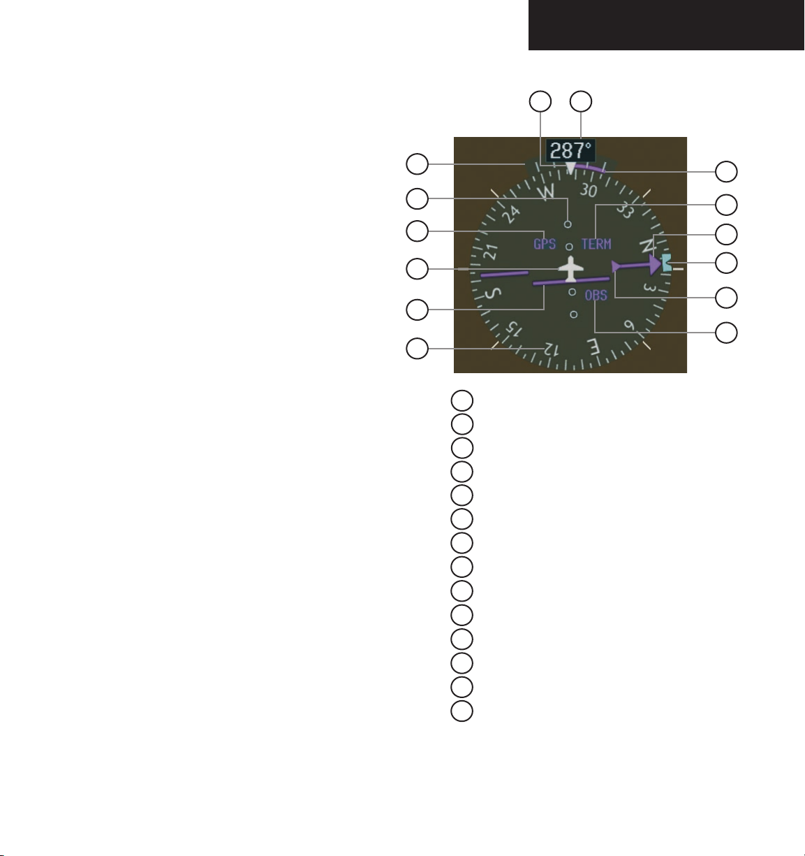
The Horizontal Situation Indicator (HSI) displays a rotating compass card with letters at the cardinal points and
numeric labels every 30 degrees. Major tick marks are
at 10-degree intervals and minor tick marks at 5 degree
intervals. The HSI is displayed in a heading-up orientation. The HSI is available in two formats (360˚ compass
rose and 140˚ arc). The HSI displays the following information:
• Heading indication
• Turn Rate Indicator
• Course Deviation Indicator
• Bearing pointers and information windows (360˚
HSI only)
• DME Information Window
• Navigation source
HSI Display Format
The HSI compass can be displayed as a 360° rose or a
140° arc by pressing the PFD softkey, followed by the 360
HSI, or the ARC HSI softkey.
360˚ HSI
The 360˚ HSI contains a course deviation indicator
(CDI), with a course pointer arrow, the TO/FROM arrow,
a sliding deviation bar and scale. The course pointer is a
single line arrow (GPS, VOR1 and LOC1) or a double line
arrow (VOR2 and LOC2) which points in the direction
of the set course. The TO/FROM arrow rotates with the
course pointer and is displayed when the active NAVAID
is received.
PRIMARY FLIGHT DISPLAY
14
13
1
2
3
4
5
6
1
Turn Rate Indicator
2
Lateral Deviation Scale
3
Navigation Source
4
Aircraft Symbol
5
Course Deviation Indicator
6
Rotating Compass Rose
7
OBS Mode
8
TO/FROM Indicator
9
Heading Bug
10
Course Pointer
11
Flight Phase
12
Turn Rate and Heading Trend Vector
13
Heading
14
Lubber Line
12
11
10
9
8
7
Figure 2-19 360˚ Horizontal Situation Indicator
Garmin G1000 Pilot’s Guide for the Diamond DA40190-00592-00 Rev. A
2-15
Page 44
PRIMARY FLIGHT DISPLAY
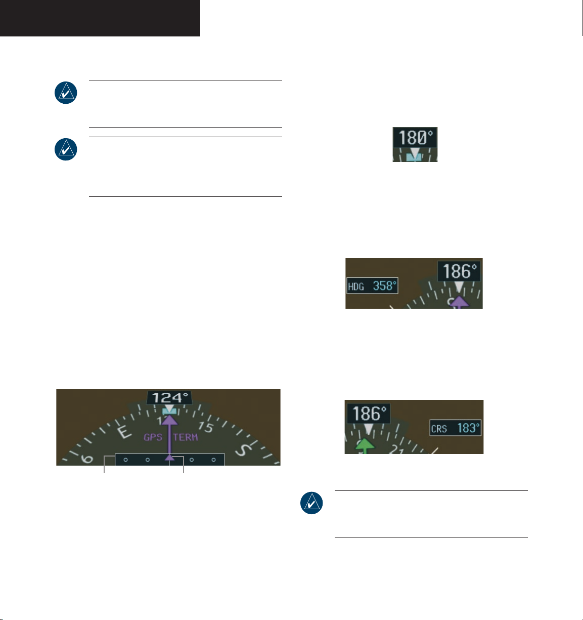
Arc HSI
NOTE: When the Arc HSI is displayed the BRG1
and BRG2 Information Windows and pointers are
disabled.
NOTE: If the pilot makes a heading change
greater than 105˚ with respect to the course, the
CDI switches to the opposite side of the deviation
scale and displays reverse sensing.
The Arc HSI is a 140˚ expanded section of the compass rose. The Arc contains a course pointer arrow, the
TO/FROM indicator, a sliding deviation indicator (the
TO/FROM and sliding deviation indicators are one and
the same), and a deviation scale. Upon station passage,
the TO/FROM indicator flips and points to the tail of the
aircraft, just like the conventional TO/FROM flag. Depending on the navigation source, the CDI on the Arc HSI
can appear in two different ways:
• GPS, OBS, VOR – Arrowhead
• Localizer – Diamond
Heading Indication
A digital reading of the current magnetic heading appears on top of the HSI. A rotatable heading bug on the
compass rose or Arc marks the desired heading.
Figure 2-21 Current Heading
When the pilot selects a heading by rotating the HDG
knob, a digital reading appears for three (3) seconds in a
box to the left of the lubber line, next to the HSI.
Figure 2-22 Selected Heading Box
When the pilot selects a course by rotating the CRS
knob, a digital reading appears for three (3) seconds in a
box to the right of the lubber line, next to the HSI.
Lateral Deviation
Scale
Figure 2-20 Arc HSI
Course Deviation and
TO/FROM Indicator
Garmin G1000 Pilot’s Guide for the Diamond DA40 190-00592-00 Rev. A2-16
Figure 2-23 Selected Course Box
NOTE: The heading displayed on the HSI is always
magnetic, even if the NAV ANGLE is set to ‘TRUE’
in the AUX System Setup Page on the MFD.
Page 45
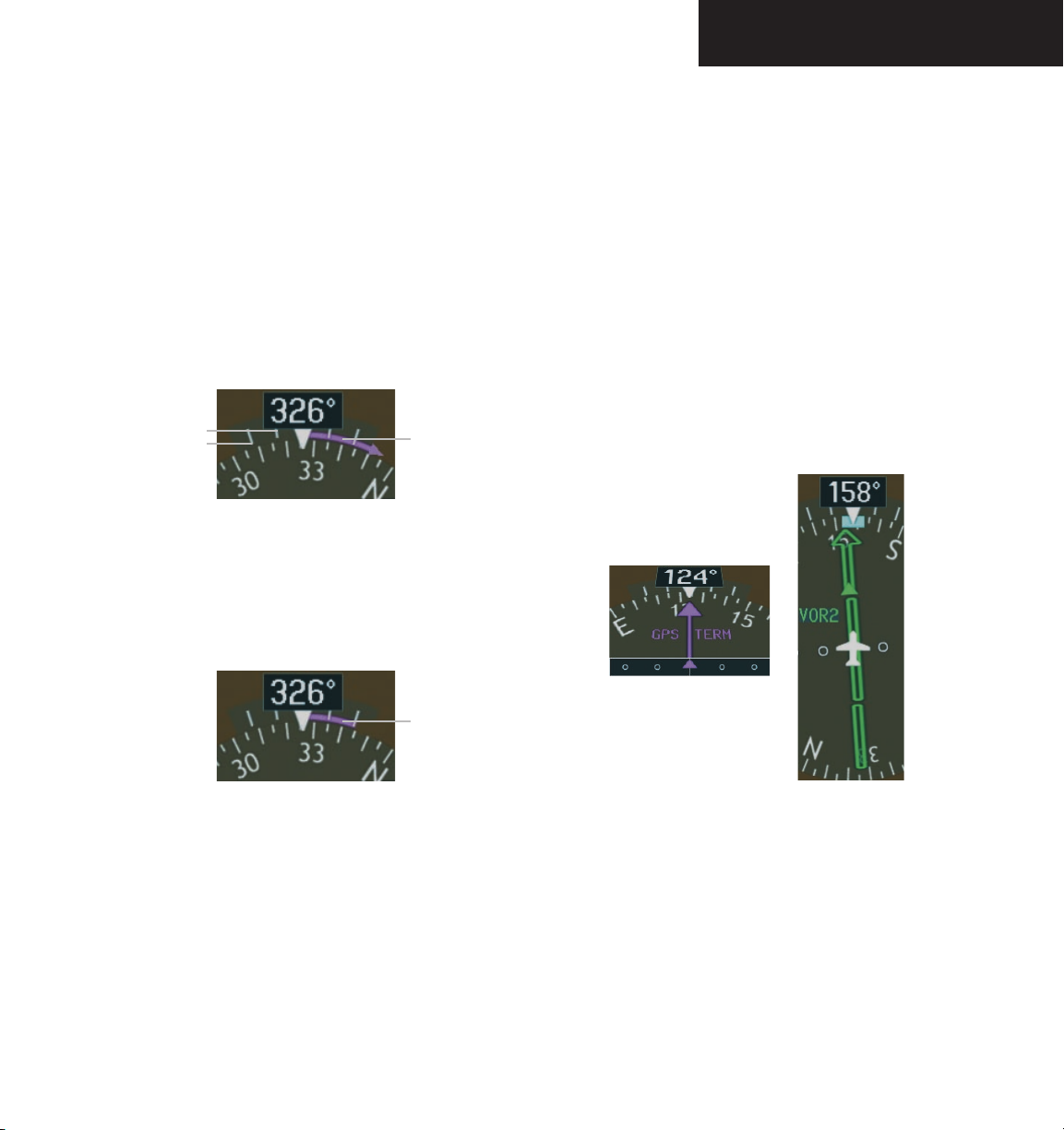
PRIMARY FLIGHT DISPLAY
Turn Rate Indicator
The Turn Rate Indicator is located directly above the
rotating compass card. Tick marks to the left and right
of the lubber line denote half-standard and standard turn
rates. A magenta turn rate trend vector shows the current
turn rate. The end of the trend vector gives the heading
predicted in six seconds, based on the present turn rate.
At rates greater than 4 deg/sec, an arrowhead appears at
the end of the magenta trend vector and the prediction is
no longer valid.
Half-Standard Turn
Rate Tick Mark
Standard Turn
Rate Tick Mark
Figure 2-24 Turn Rate Indicator and Trend Vector
A standard-rate turn (3 deg/sec) is shown on the indicator by the trend vector stopping at the standard turn
rate tick mark, corresponding to a predicted heading of 18
degrees from the current heading.
Turn Rate
Trend Vector
(rate > 4 deg/sec)
Course Deviation Indicator
The Course Deviation Indicator (CDI) moves left or
right from the course pointer along a deviation scale to
display aircraft position relative to the course.
The CDI has the same angular limits as a mechanical
CDI when coupled to a VOR or LOC. When coupled
to GPS, the full scale limits for the CDI are defined by a
GPS-derived distance (5.0, 1.0, or 0.3 nm). The CDI scale
automatically adjusts to the desired limits based upon the
current phase of flight (en route: 5.0 nm, terminal area:
1.0 nm, or approach: 0.3 nm). The desired GPS scale set
tings may be selected manually from the MFD (refer to the
Multi Function Display section).
-
Turn Rate
Trend Vector
(standard rate)
Figure 2-25 Standard-Rate Turn Indication
Garmin G1000 Pilot’s Guide for the Diamond DA40190-00592-00 Rev. A
Figure 2-26 Arc CDI and Compass Rose CDI
2-17
Page 46
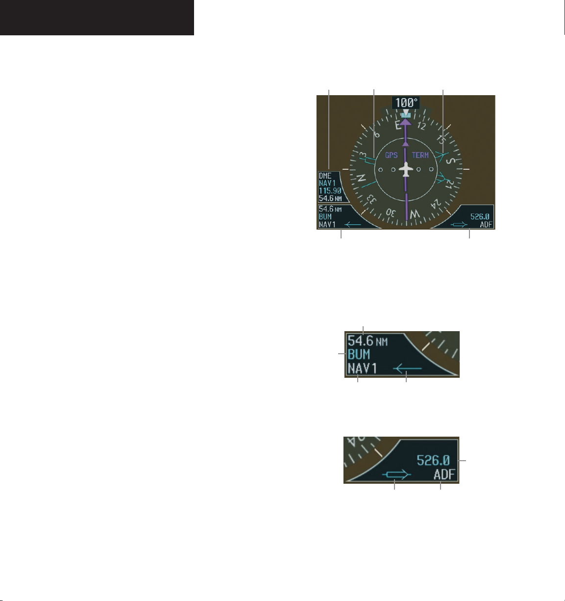
PRIMARY FLIGHT DISPLAY
Bearing Pointers and Information Windows
Up to two bearing pointers can be displayed on the
HSI. Pressing the PFD softkey provides access to the
BRG1 and BRG2 softkeys. The BRG1 pointer is a single
cyan line with an open arrowhead at the end. The BRG2
pointer is a double cyan line with an open arrowhead at
the end. The bearing pointers never override the CDI.
When at least one bearing pointer is displayed (but not
necessarily visible if there is no data available), a white
ring appears around the center of the compass rose to visually separate the bearing pointer(s) from the CDI.
When a bearing pointer is displayed, its associated
Information Window is also displayed. The Bearing 1
(BRG1) Information Window is displayed to the lower
left of the HSI and includes the bearing source (NAV1 or
GPS), a pointer icon, frequency (NAV1), and distance to
the bearing source. The Bearing 2 (BRG2) Information
Window is displayed to the lower right of the HSI and in
cludes the bearing source (NAV2 or GPS), a pointer icon,
frequency (NAV2), and distance to the bearing source.
-
DME
Information
Window
Bearing 1
Information
Window
Bearing 2
Pointer
Figure 2-27 HSI with Bearing Information
Distance to
Bearing Source
Bearing 1
Pointer
Bearing 2
Information
Window
If GPS is the bearing source, the active waypoint
identifier is displayed in lieu of a frequency. If an active
waypoint is not selected, the bearing pointer is removed
from the HSI and “NO DATA” is displayed in the informa
-
tion window.
If the NAV radio is the bearing source and is tuned to
an ILS frequency, the bearing pointer is removed from the
HSI and the frequency is replaced with “ILS”. If the NAV
radio is not receiving the tuned VOR station, the bear
ing pointer is removed from the HSI and the frequency
field displays “NO DATA”. When NAV1 or NAV2 is the
selected bearing source, the frequency is replaced by the
station identifier when the station is in range.
Garmin G1000 Pilot’s Guide for the Diamond DA40 190-00592-00 Rev. A2-18
Waypoint
Identifier
Bearing
Source
Figure 2-28 BRG1 Information Window
Figure 2-29 BRG2 Information Window
Pointer
Icon
Pointer
Icon
Waypoint
Frequency
Bearing
Source
Page 47
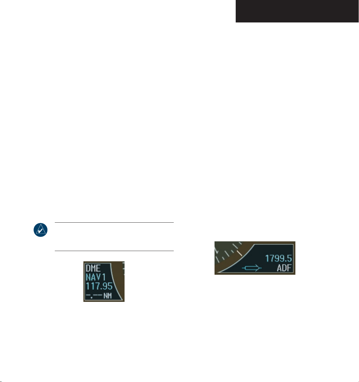
PRIMARY FLIGHT DISPLAY
DME Radio (optional)
The DME radio is a Honeywell KN63 remote mounted,
200-channel, 100-watt, all-solid-state digital DME which
provides distance information to the G1000.
Press the
to display the DME Information Window. The DME Information Window is displayed above the BRG1 Informa
tion Window and displays the DME label, tuning mode
(NAV1, NAV2, or HOLD), frequency, and distance. When
a signal is invalid, the distance is replaced by “–.– – NM.”
The pilot may select from three DME tuning modes:
• NAV1 – Tunes the DME frequency from the selected
• NAV2 – Tunes the DME frequency from the selected
• HOLD – When transitioning from NAV1 or NAV2
PFD softkey followed by the DME softkey
-
NAV1 frequency
NAV2 frequency
mode to Hold mode, the DME frequency remains
set to the last selected NAV frequency
NOTE: When navigating in GPS mode, the distance displayed is the GPS-derived great-circle
distance, not the actual DME distance.
ADF Radio (optional)
The ADF radio is a Becker RA3502 (1) remote mount-
ed ADF radio receiver that operates in the frequency range
190.0 to 1799.5 kHz in 0.5 kHz increments.
The ADF bearing source is selected by pressing the
PFD softkey, then by pressing the BRG1 or BRG2 softkey
(as desired) until ADF is displayed.
The audio volume for the ADF is displayed and ad
justed from the Radio Tuning window. The ADF radio has
three tuning modes as described below:
• ANT (antenna) mode – Parks the ADF pointer at
the three-o’clock position on the HSI
The Morse code can also be identified.
• BFO (beat frequency oscillator) mode – Provides
an audible tone detected through the receiver when
a frequency is tuned in
No Morse code is heard.
• ADF mode – The ADF bearing pointer should
point to the station
The Morse code can also be identified.
-
Figure 2-30 DME Information Window
Garmin G1000 Pilot’s Guide for the Diamond DA40190-00592-00 Rev. A
Figure 2-31 ADF Selected in BRG2 Information Window
2-19
Page 48
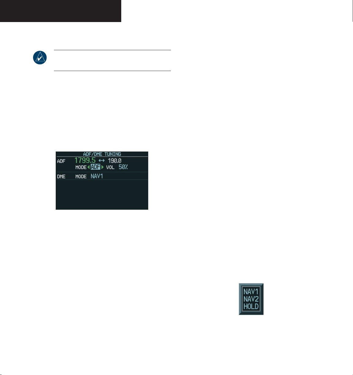
PRIMARY FLIGHT DISPLAY
Radio Tuning Window (optional)
NOTE: The Radio Tuning window is only available
if the DME and/or ADF radios are installed.
The Radio Tuning window is displayed by pressing the
ADF/DME (ADF, DME, or ADF/DME depending on the
installation) softkey. This window provides display and
control of single or dual ADF and DME radio(s). Depend
ing on the installation, the Radio Tuning window may be
titled ADF Tuning, DME Tuning, or ADF/DME Tuning.
There are two ADF frequency fields, active (green) and
standby (white).
Figure 2-32 Radio Tuning Window
-
The ENT key is used to transfer the ADF standby and
active frequency whenever the cursor is highlighting a
standby frequency.
Any time the cursor is on the ADF standby frequency,
and the standby frequency is not in “edit” mode, the “ENT
TO TRANSFER” message is displayed at the bottom of the
Radio Tuning window to assist the pilot in performing the
transfer.
To change the ADF mode:
1. From the Radio Tuning window, turn the
FMS
knob to highlight the ADF mode field.
2. Turn the
small FMS
knob in the direction of the
large
green arrow(s) to select the desired mode of
operation.
To change the ADF volume:
1. From the Radio Tuning window, turn the
FMS
knob to highlight the volume field.
2. Turn the
small FMS
the volume. Turn the
knob to the left to decrease
small FMS
knob to the
large
right to increase the volume.
To change the DME mode:
To edit the standby ADF frequency:
1. From the Radio Tuning window with the
standby ADF frequency highlighted, turn the
small FMS
knob to place the cursor on the first
digit.
FMS
2. Turn the
quency and press the
knobs to enter the desired fre-
ENT
key. The standby
frequency is now highlighted.
ENT
3. Press the
key again to transfer the standby
frequency to the active frequency field.
Garmin G1000 Pilot’s Guide for the Diamond DA40 190-00592-00 Rev. A2-20
1. From the Radio Tuning window, turn the
FMS
knob to highlight the DME mode field.
2. Turn the
small FMS
tion window. Turn the
desired mode and press the
Figure 2-33 DME Selection Window
knob to display the selec-
FMS
knob to select the
ENT
key.
large
Page 49
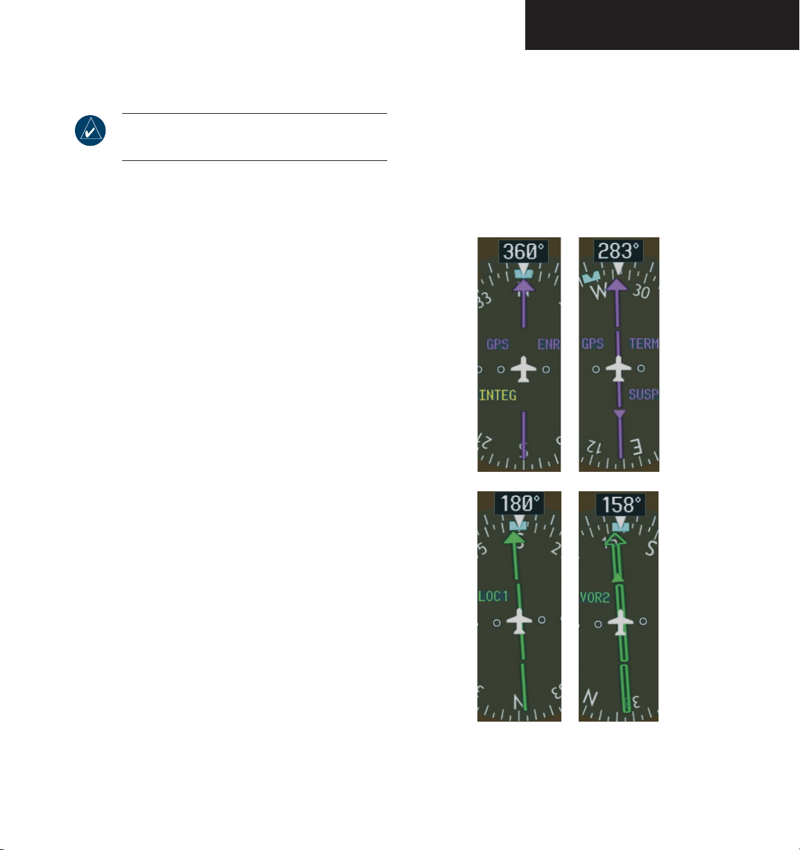
PRIMARY FLIGHT DISPLAY
Navigation Source
NOTE: OBS is only available with the active flight
plan leg, when navigating under GPS.
The HSI can display two sources of navigation: GPS
or NAV (VOR, localizer, and glideslope). In GPS mode,
the flight plan legs are sequenced automatically. Enabling
OBS mode suspends auto sequencing of waypoints, but
retains the current “active-to” waypoint as the navigation
reference even after passing the waypoint. When OBS is
disabled, the GPS returns to normal operation, with automatic sequencing of waypoints. OBS mode also allows
the pilot to set the desired course TO/FROM a waypoint.
Color indicates the current navigation source: magenta
(for GPS) or green (for VOR and LOC). As the pilot cross
es the MAP, “SUSP” appears on the HSI in place of “OBS”
and the
OBS softkey (now) reads “SUSP”, indicating that
automatic sequencing of approach waypoints is suspended at the MAP. The following yellow annunciations may
appear on the HSI:
-
To enable/disable OBS mode while navigating
with GPS
1. Press the
:
OBS softkey to select OBS Mode.
2. Turn the small CRS knob to select the desired
course TO/FROM the waypoint.
3. Press the OBS softkey again to return to normal
operation.
• INTEG – RAIM not available
• WARN – GPS detects position error
To change between navigation sources:
1. Press the
CDI softkey to change from GPS to
VOR1 or LOC1. This places the cyan tuning box
over the NAV1 standby frequency in the upper
left corner of the PFD.
2. Press the
CDI softkey again to change from
VOR1 or LOC1 to VOR2 or LOC2. This places
the cyan tuning box over the NAV2 standby
frequency.
CDI
3. Press the
softkey a third time to return to
GPS.
Garmin G1000 Pilot’s Guide for the Diamond DA40190-00592-00 Rev. A
Figure 2-34 GPS INTEG, GPS SUSP, LOC1 and VOR2
2-21
Page 50
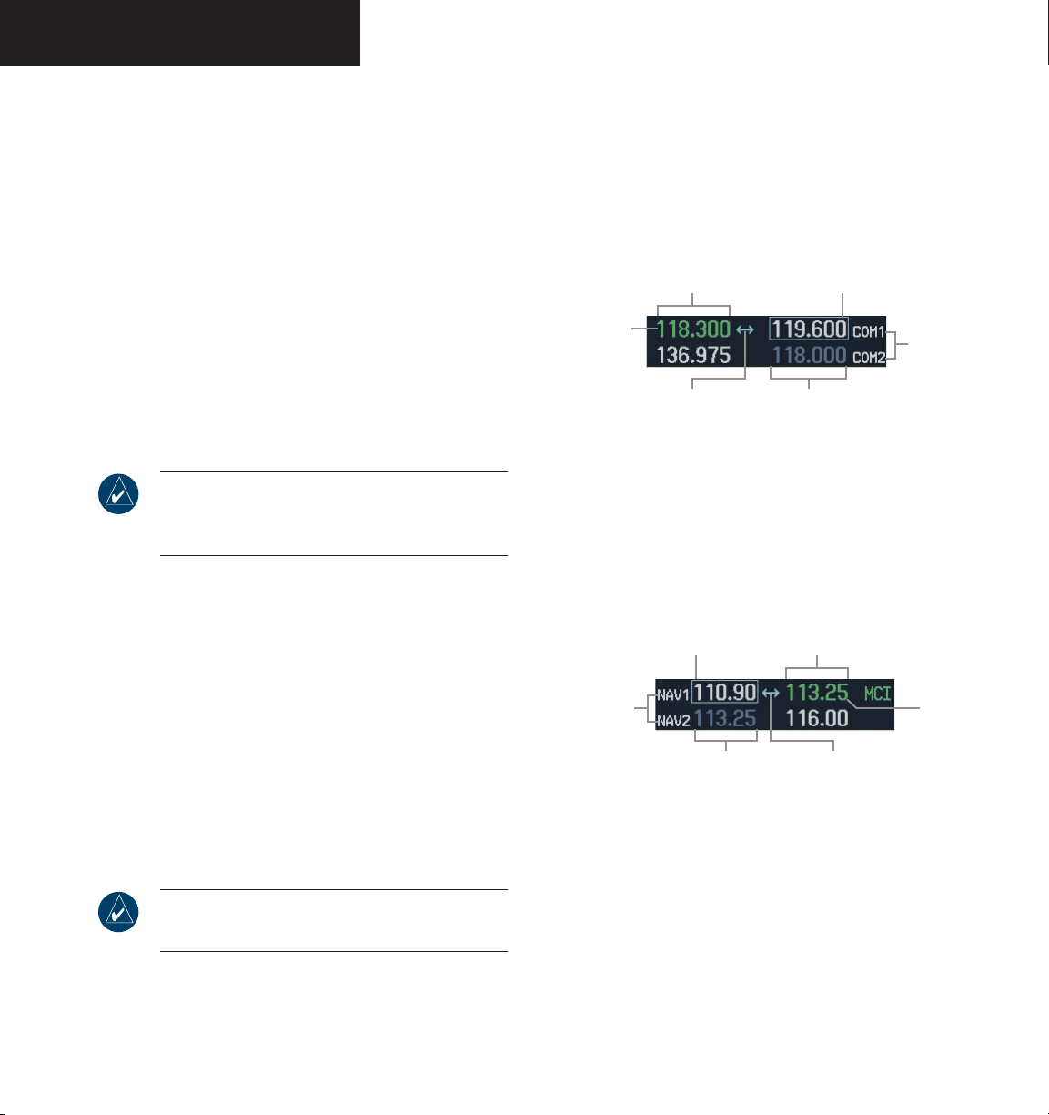
PRIMARY FLIGHT DISPLAY
2.5 COMMUNICATION,
NAVIGATION, & SURVEILLANCE
COMMUNICATION FREQUENCY WINDOW
The Communication (COM) Frequency Window,
located in the upper right corner of the PFD, provides
control and display of dual VHF Radio Communication
Transceivers (COM1 and COM2). The COM Frequency
Window displays the following information:
• COM1 and COM2 active and standby frequencies
• Color-coded indication of the active COM transceiver
NOTE: Operating procedures for the COM Frequency Window are located in the NAV/COM
section.
NAVIGATION FREQUENCY WINDOW
The Navigation (NAV) Frequency Window, located in
the upper left corner of the PFD, provides control and
display of dual VOR/ILS receivers (NAV1 and NAV2). The
NAV Frequency window displays the following information:
• NAV1 and NAV2 active and standby frequencies
• NAV1 and NAV2 identifier, if the active NAV1 or
NAV2 frequency is a valid, identified frequency
• Color-coded indication of the active NAV receiver
Selected COM
Radio
(Green)
Figure 2-35 Communication Frequency Window
NAV Receivers
Active COM
Frequency Field
Frequency
Toggle Arrow
Frequency
Tuning Box
Standby NAV
Frequency Field
Figure 2-36 Navigation Frequency Window
Frequency
Tuning Box
Standby COM
Frequency Field
Active NAV
Frequency Field
Frequency
Toggle Arrow
COM Radios
Selected NAV
Receiver
(Green)
NOTE: Operating procedures for the NAV Frequency
Window are located in the NAV/COM section.
Garmin G1000 Pilot’s Guide for the Diamond DA40 190-00592-00 Rev. A2-22
Page 51
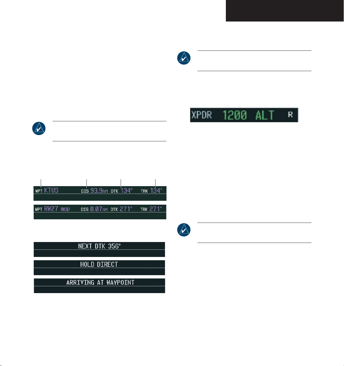
PRIMARY FLIGHT DISPLAY
NAVIGATION STATUS BAR
The Navigation Status bar is located at the top of the
PFD and displays valuable information while flying a
route:
• The next waypoint in the active flight plan
• Distance to the next waypoint (DIS)
• Desired track to the next waypoint (DTK)
• Current track angle (TRK)
• GPS Navigation Annunciations
NOTE: The fields in the PFD Navigation Status
bar cannot be changed.
Desired Track
Next Waypoint
Distance to
Next Waypoint
To
Next Waypoint
Current Track
TRANSPONDER (XPDR) STATUS BAR
NOTE: Refer to the Transponder section for information regarding transponder operation.
The Transponder (XPDR) Status Bar is located in the
lower right corner and displays the transponder code, reply symbol, and mode of operation.
Figure 2-39 Transponder Status Bar
Transponder code selection is performed with eight
softkeys (0-7) providing 4,096 active identification codes.
Pressing one of these softkeys begins the code selection
sequence. The new code is activated five seconds after the
fourth digit is entered. The BKSP softkey removes one
digit at a time until the status bar is empty. The VFR softkey can be used to enter the pre-programmed VFR code
(1200 in the USA only) selected in G1000 configuration
mode.
Figure 2-37 Navigation Status Bar Information Examples
Figure 2-38 Navigation Status Bar Messages
Garmin G1000 Pilot’s Guide for the Diamond DA40190-00592-00 Rev. A
NOTE: Refer to ICAO standards for VFR codes in
other countries.
Pressing the IDENT softkey activates the Special Position Identification (SPI) pulse for 18 seconds, identifying
the transponder return on the ATC screen.
2-23
Page 52
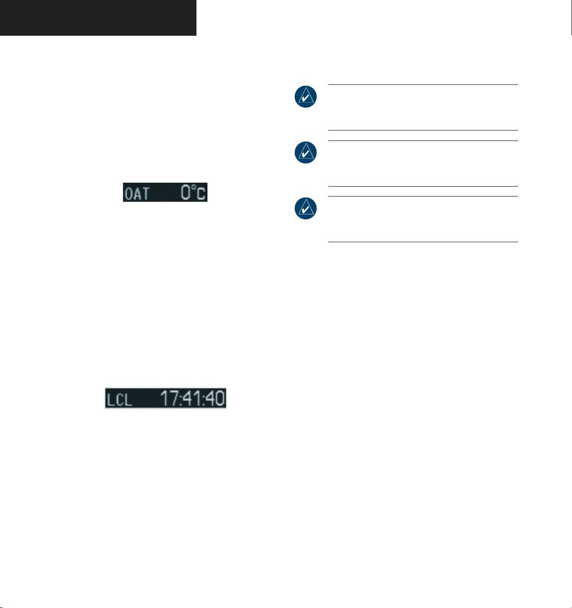
PRIMARY FLIGHT DISPLAY
2.6 SUPPLEMENTAL FLIGHT DATA
OUTSIDE AIR TEMPERATURE BOX
The outside air temperature (OAT) is displayed in °C
with the “OAT” label. °F can be displayed using the AUX
System Setup Page on the MFD (refer to the Multi Function Display section).
Figure 2-40 Outside Air Temperature Box
SYSTEM TIME BOX
The System Time box displays the local time. Time
and date are obtained from the satellites and cannot be
changed. The pilot may select the desired time format
and offset. There are three time formats available: Local
12-hr, Local 24-hr, and Coordinated Universal Time
(UTC). The Time Offset (Time Zone) represents the number of hours plus or minus UTC (refer to the Multi Function Display section).
Figure 2-41 System Time Box
INSET MAP
NOTE: The Inset Map orientation is always
the same as that for the MFD Navigation Map
Page.
NOTE: Map orientation and other map features
are enabled on the MFD (refer to the Multi Function Display section).
NOTE: Refer to the Multi Function Display section for a detailed explanation of the declutter
levels.
The Inset Map is a smaller version of the MFD Navigation Map Page. It appears in the lower left corner of the
PFD and is displayed by pressing the INSET softkey. The
map disappears from the PFD when pitch exceeds +30° or
–20° or when a 65° bank angle is reached. The direct-to
function is not available from the Inset Map. The fuel
reserve rings are enabled and disabled from the MFD only.
The Inset Map displays the following information:
• Moving map with orientation references
– North Up
– Track Up
– DTK Up
– HDG Up
• Zoom range legend
• Declutter levels (3)
• Aircraft icon
• Traffic data
• Topographic data
• Terrain data
• Weather information (optional)
• Enabled map features
• Active navigation route
• Track vector
• Fuel ring (reserve)
Garmin G1000 Pilot’s Guide for the Diamond DA40 190-00592-00 Rev. A2-24
Page 53
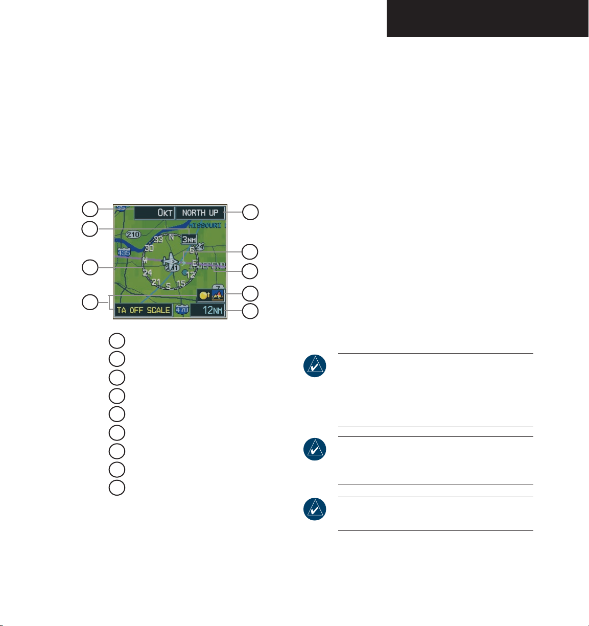
PRIMARY FLIGHT DISPLAY
The following Inset Map operations can be performed
independently of the MFD:
• Change zoom range
• Change declutter level
• Enable/disable traffic data
• Enable/disable topographic data
• Enable/disable terrain data
• Enable/disable weather information (optional)
• Pan Map
1
2
3
4
Wind Vector
1
9
8
7
6
5
To change the zoom range:
Turn the
joystick
clockwise to increase or
counterclockwise to decrease the range. Zoom
ranges from 500 feet to 2,000 nautical miles.
To change the declutter level:
INSET
1. Press the
2. Press the
softkey.
DCLTR
softkey to remove background
map details until the desired amount of detail is
depicted. The declutter level appears above the
softkey (i.e. DCLTR-1). Refer to the Multi Function Display Pilot’s Guide for more detail.
To enable/disable traffic data:
1. Press the
2. Press the
INSET
TRAFFIC
softkey.
softkey to display Traffic
Information Service (TIS) traffic. Traffic symbol
ogy appears next to the aircraft icon and at the
bottom right corner of the map.
3. Press the
TRAFFIC
softkey again to remove data
from the map.
-
2
NAV Compass Range
NAV Compass
3
Traffic Icon and Scale
4
5
Map Range
Terrain Icon
6
7
Active Navigation Route
Track Vector
8
9
Map Orientation
Figure 2-42 Inset Map
Garmin G1000 Pilot’s Guide for the Diamond DA40190-00592-00 Rev. A
NOTE: TIS displays traffic within seven nautical
miles from 3,000 feet below to 3,500 feet above
the requesting aircraft, and includes location,
direction, altitude, and climb/descent information.
NOTE: If a second TA appears or if the number
of TAs displayed decreases then increases, new
audio and visual alerts are generated.
NOTE: Refer to the Appendix for more details
about Traffic Information Service (TIS).
2-25
Page 54
PRIMARY FLIGHT DISPLAY
To enable/disable topo data:
INSET
1. Press the
2. Press the
softkey.
TOPO
softkey to display topographic
land colors, which represent the rise and fall
of land elevation.
TOPO
3. Press the
softkey again to remove topo
data from the map.
NOTE: When topographic data is removed from
the display, all cartographic data is automatically
removed and the Jeppesen Nav Data is presented
on a black background.
To enable/disable terrain data:
INSET
1. Press the
2. Press the
softkey.
TERRAIN
softkey to display color-coded
terrain tiles, which are based upon the aircraft
current altitude. A mountain icon appears above
the zoom range at the lower right corner of the
map, showing that terrain is selected.
Red (warning) – Land elevation is within 100
ft of the aircraft current altitude or above.
Yellow (caution) – Land elevation is greater
than 100 ft to 1,000 ft below aircraft altitude.
Black – Land elevation greater than 1,000 ft
below aircraft altitude.
3. Press the
TERRAIN
terrain data from the map.
NOTE: Terrain data is not displayed when the
aircraft latitude is greater than 75˚ N or 60˚ S.
softkey again to remove the
NOTE: Refer to the Optional Equipment section
for more details about weather options.
To enable/disable Stormscope (optional),
NEXRAD (optional), or XM lightning
(optional) data:
1. Press the
(optional),
softkey. Press the
NEXRAD
(optional), or
STRMSCP
XM LTNG
INSET
(optional) softkey to display weather informa
tion.
2. Press the
STRMSCP, NEXRAD, or XM LTNG
key again to remove the weather information
from the map.
To pan the map:
NOTE: The joystick on the PFD operates inde-
pendently from the one on the MFD.
1. Push in the
joystick
to display the panning pointer.
This allows the pilot to move the map beyond its
current limits without adjusting the range.
joystick
2. Push in and move the
to pan the map
in the general direction of the desired location.
When the pointer is placed on an object, the name
of the object is highlighted for approximately four
seconds (even if the name was not originally
displayed on the map). This feature applies to
everything displayed on the map except for route
lines.
3. Push in the
joystick
again to cancel the panning
function and return to the present position on
the map.
-
soft-
NOTE: Refer to the Appendix for more details
about terrain.
Garmin G1000 Pilot’s Guide for the Diamond DA40 190-00592-00 Rev. A2-26
NOTE: The airspace boundary stays highlighted
for approximately four seconds before returning
to normal shading.
Page 55
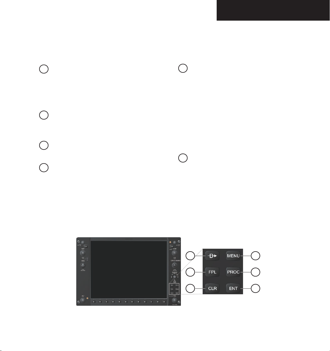
AUXILIARY WINDOW KEYS
The main keys which are used in association with PFD
Auxiliary Window operations are listed below:
1
DIRECT-TO – Activates the direct-to func-
tion and allows the user to enter a destination
waypoint and establishes a direct course to the
selected destination (specified by identifier chosen
from the active route)
2
FPL – Displays the active Flight Plan Page
for creating and editing the active flight plan or
accessing stored flight plans
3
CLR – Erases information, cancels an entry, or
removes page menus
4
MENU – Displays a context-sensitive list of
options
This option list allows the user to access addi
tional features or make setting changes which
relate to certain pages.
PRIMARY FLIGHT DISPLAY
5
PROC – Selects approaches, departures and
arrivals for the flight plan.
When using a flight plan, available procedures
for departure and/or arrival airport are offered
automatically. If a flight plan is not used, the
desired airport, then the desired procedure may
be selected. This key selects IFR departure
procedures (SIDs), arrival procedures (STARs) and
approaches (SIAPs) from the database and loads
them into the active flight plan.
6
ENT – Accepts a menu selection or data entry
This key is used to approve an operation or
complete data entry. It is also used to confirm
-
information.
The MENU key opens the PFD Setup Menu if no
Auxiliary Window is open.
Figure 2-43 PFD Auxiliary Window Keys
Garmin G1000 Pilot’s Guide for the Diamond DA40190-00592-00 Rev. A
1
2
3
4
5
6
2-27
Page 56
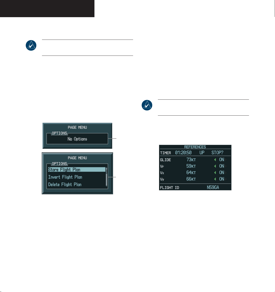
PRIMARY FLIGHT DISPLAY
WORKING WITH MENUS
NOTE: Pressing a softkey does not display a menu
or sub-menu.
Much G1000 operation is accomplished using a menu
interface. The G1000 has a bezel-mounted dedicated
MENU key that displays a context-sensitive list of options when pressed. This option list allows the pilot to
access additional features or make setting changes specifically relating to the currently displayed window. There
is no all-encompassing menu. Some menus provide access to additional sub-menus that are in turn used to view,
edit, select, and review options.
No Options
with NRST
Window
Displayed
AUXILIARY WINDOWS
The lower right area of the PFD is a shared area that, at
any one time, can present the following windows:
• TIMER/REFERENCES
• NEAREST
• DIRECT-TO
• FLIGHT PLAN
• PROCEDURES
Timer/References Window
NOTE: Refer to the Aircraft Flight Manual (AFM)
for limitations.
The Timer/References Window is enabled and disabled
by pressing the TMR/REF softkey. The Generic Timer
and Vspeed references are set using this window.
Figure 2-44 Page Menu Examples
To navigate the Page Menu Window:
FMS
1. Turn the
knob to scroll through a list of
available options (a scroll bar always appears
to the right of the window when the option
list is longer than the window).
ENT
2. Press the
key to select the desired
option.
CLR
3. The
key or the FMS knob may be pressed to
remove the menu and cancel the operation.
Garmin G1000 Pilot’s Guide for the Diamond DA40 190-00592-00 Rev. A2-28
Options with
FPL Window
Displayed
Figure 2-45 Timer/References Window
The following Vspeeds and Vspeed bugs can be set using the Timer/References Window:
• Best glide speed reference
• Best glide speed bug (ON, OFF)
• Rotation speed reference (V
• V
bug (ON, OFF)
R
• Best angle-of-climb speed reference (V
• V
bug (ON, OFF)
X
• Best rate-of-climb speed reference (V
• V
bug (ON, OFF)
Y
)
R
)
X
)
Y
Page 57
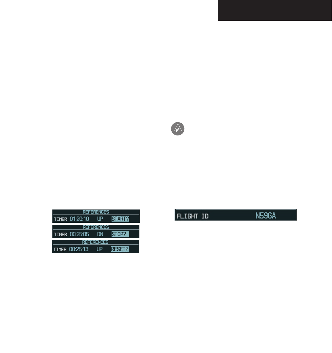
PRIMARY FLIGHT DISPLAY
Generic Timer
The Generic Timer displays time (hr:min:sec), timer
count direction (UP or DOWN), and timer status (START,
STOP, or RESET).
To change the Generic Timer:
1. Press the
FMS
knob to select the time field (hh/mm/ss).
2. Turn the
then press the
TMR/REF
FMS
softkey, then turn the
large
knobs to set the desired time,
ENT
key. The UP/DOWN field is
now highlighted.
3. Turn the
small FMS
knob to display the UP/
DOWN window.
FMS
4. Turn the
then press the
knob to select ‘UP’ or ‘DOWN’,
ENT
key. ‘START?’ is now high-
lighted.
ENT
5. Press the
key to START, STOP, or RESET the
timer (if the timer is counting DOWN, it must
be reset manually).
6. Press the
key or the
TMR/REF
softkey to
CLR
remove the window.
Flight ID
Flight status automatic reporting of aircraft identifica
tion (ID) is transmitted by the transponder to the ground
stations and other aircraft.
The flight ID is set to fixed (“SAME AS TAIL” and
“CONFIG ENTRY”) or variable (“PFD ENTRY”) at the time
of installation. The two fixed selections do not require any
action from the pilot. The variable (“PFD ENTRY”) flight ID
requires the pilot to enter the flight ID in the Timer/Refer
-
ences Window each time the G1000 is powered on.
NOTE: If the G1000 is set to variable (“PFD
ENTRY”) and the flight ID entry field in the Timer/
References Window is not visible, the pilot should
contact a Garmin-authorized Service Center.
To enter or change the Flight ID:
1. Press the
FMS
knob to highlight the flight ID field.
2. Turn the
ID. Press the
TMR/REF
FMS
softkey, then turn the
large
knobs to enter the desired flight
ENT
key to update the flight ID.
Figure 2-46 Timer Status Prompts
Garmin G1000 Pilot’s Guide for the Diamond DA40190-00592-00 Rev. A
Figure 2-47 Flight ID Field
2-29
Page 58
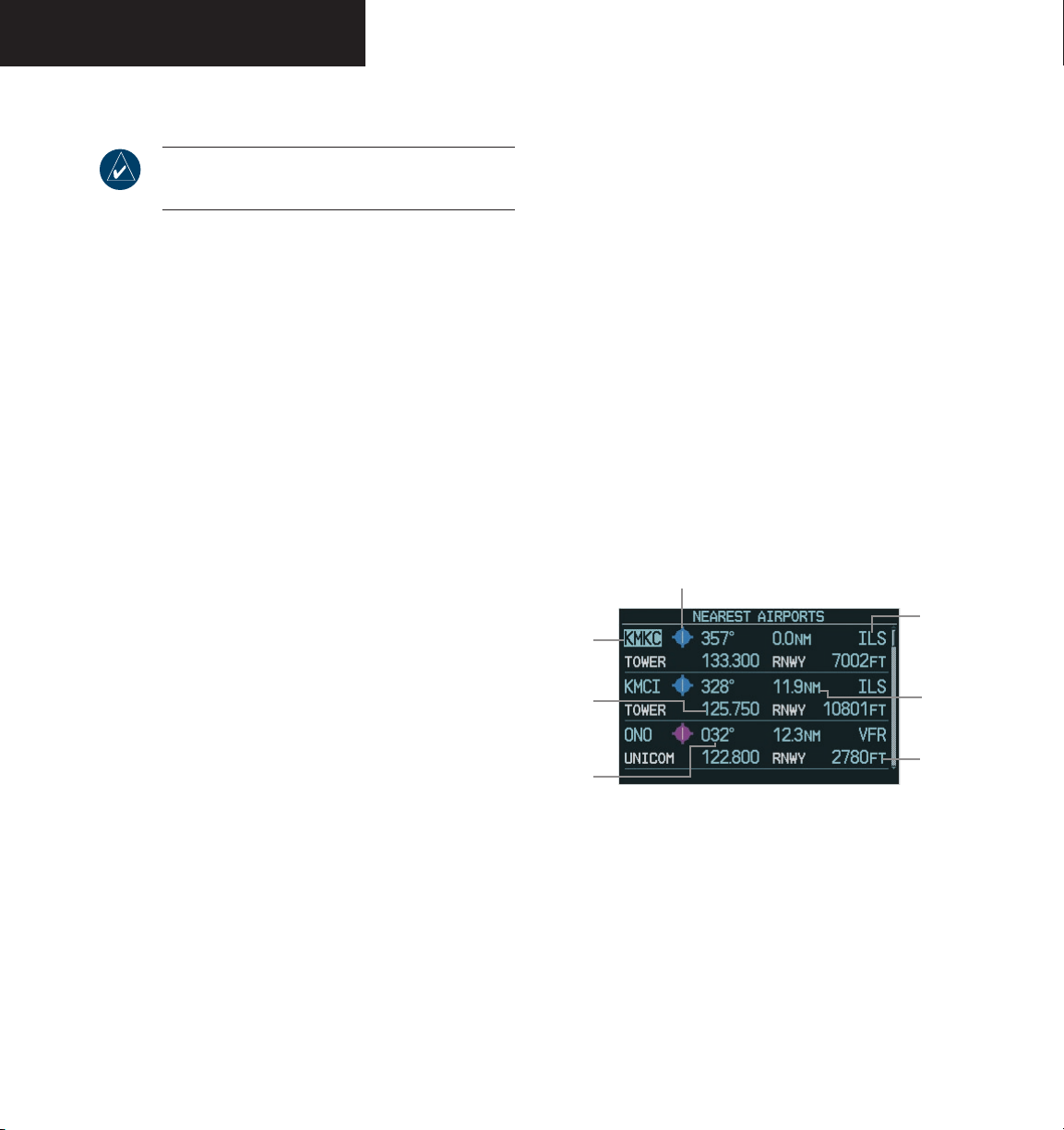
PRIMARY FLIGHT DISPLAY
Vspeeds and Vspeed Bug Status
NOTE: Default settings are automatically restored
when power is cycled.
Vspeed values for the aircraft can be found in the Aircraft Flight Manual (AFM). The Vspeeds can be changed
and the Vspeed bugs can be turned ON or OFF:
To change Vspeeds and turn the Vspeed
bug ON or OFF:
1. Press the
FMS
knob to highlight the field of the Vspeed
TMR/REF
softkey, then turn the
large
to be changed.
2. Turn the
speed and press the
small FMS
knob to select the desired
ENT
key (when a speed has
been changed, an asterisk appears next to the
speed). The ON/OFF field is now highlighted.
3. To change each setting individually, turn the
small FMS
knob in the direction of the green
arrowhead.
4. All Vspeed references can be changed simulta
neously by pressing the
MENU
key and select
-
‘All References ON’ or ‘All References OFF’, then
press the
ENT
key.
To restore all defaults:
1. From the Timer/References Window, press the
MENU
key
FMS
2. Turn the
Defaults’ and press the
3. Press the
knob to highlight ‘Restore
ENT
key.
TMR/REF
softkey to remove the
window.
Nearest Airports Window
Pressing the NRST softkey enables/disables the Nearest Airports Window. From the Nearest Airports Window,
information for a selected airport can be viewed, the active
primary communications frequency can be selected, and
direct-to navigation can be activated.
The Nearest Airports Window displays the 25 nearest
airports with the following information:
• Identifier
• Airport symbol
• Bearing to
• Distance from
• Best approach available
• Primary communication frequency
• Length of longest hard surface runway (or soft
surface, if no hard surface runway exists)
Airport Symbol
Best
Approach
Identifier
Primary
COM
Frequency
Bearing
To
Figure 2-48 Nearest Airports Window
Available
Distance
Runway
Length
Garmin G1000 Pilot’s Guide for the Diamond DA40 190-00592-00 Rev. A2-30
Page 59
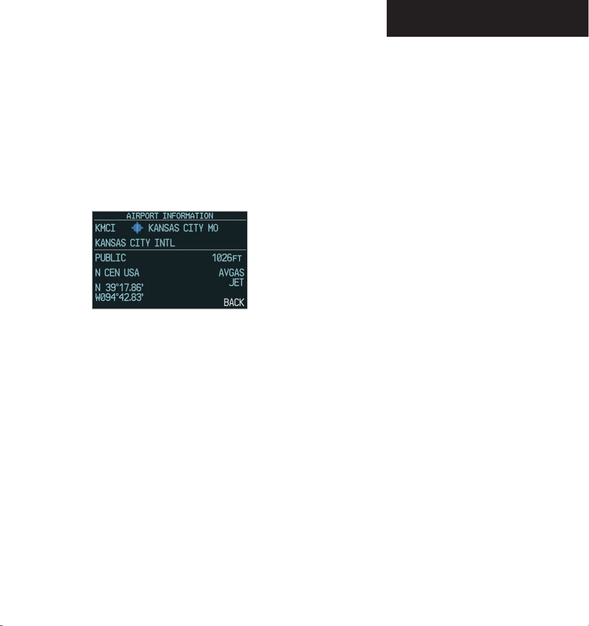
PRIMARY FLIGHT DISPLAY
To view information about an airport:
NRST
1. Press the
softkey to display a list of the
Nearest Airports.
2. Turn the
and press the
FMS
knob to select the desired airport
ENT
key. The airport information
is displayed with ‘BACK’ highlighted at the
bottom of the window.
3. When finished viewing the airport informa
tion, press the
ENT
key to return to the nearest
airports list.
Figure 2-49 Airport Information Window
To select an airport from the Airport Information Window by the airport identifier,
location, and name fields:
1. From the Nearest Airport window, turn the
large FMS
2. Turn the
tion, then press the
3. Turn the
then press the
knob to highlight the desired field.
FMS
knobs to select the desired loca-
ENT
key.
large FMS
knob to highlight ‘BACK’,
ENT
key.
To activate a Direct-to from the Nearest
Airports Window:
1. From the Nearest Airports Window, turn the
large FMS
then press the
knob to highlight the desired airport,
Direct-to
key. The Direct-to
Window appears.
2. Press the
-
To activate a Direct-to from the Airport
ENT
key twice to activate.
Information Window:
1. From the Airport Information Window, press
the
Direct-to
2. Press the
key.
ENT
key twice to activate.
To select a COM frequency:
From the Nearest Airports Window, turn the
large FMS
quency, then press the
knob to highlight the desired fre-
ENT
key. The frequency
is placed in the tuning box.
Garmin G1000 Pilot’s Guide for the Diamond DA40190-00592-00 Rev. A
2-31
Page 60
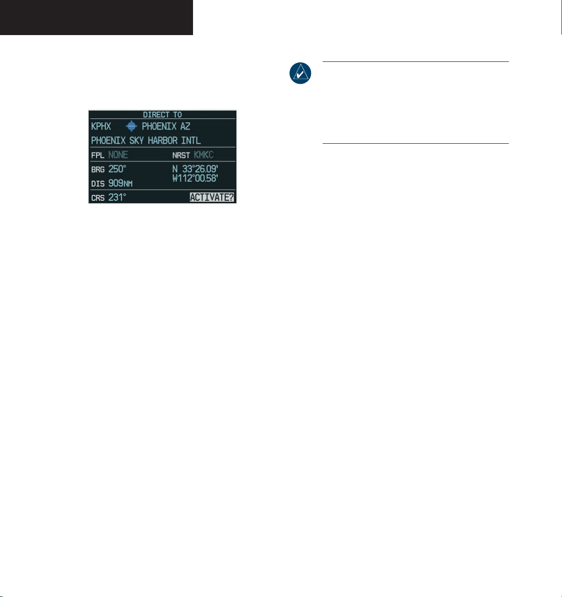
PRIMARY FLIGHT DISPLAY
Direct-to Window
The Direct-to Window is enabled/disabled by pressing
the Direct-to key.
NOTE: When entering an all-letter/alphabetical
airport identifier (only in the USA), the pilot must
precede it with the letter “K” (e.g., KMCI). If the
airport identifier is alpha-numeric, simply enter
the three-digit identifier (e.g., 51K). The full ICAO
identifier must be entered for all waypoints.
To select a Direct-to by identifier:
1. Press the
Direct-to
key, then turn the
to select the desired waypoint identifier. Press
the
ENT
key to confirm the selection.
FMS
knobs
Figure 2- Direct-to Window
The currently selected waypoint displays the following
information:
• Identifier
• Waypoint symbol
• Waypoint location
• Facility name
• Flight plan waypoint list
• Nearest waypoint List
• Bearing to waypoint
• Distance from waypoint
• Latitude/longitude
• Course to selected waypoint
Direct-to Navigation
Selection of a waypoint for Direct-to navigation may be
done in several ways:
• By specifying the identifier, waypoint location, or
facility name
• From a list of waypoints in the active flight plan
• From a list of the 25 nearest airports
ENT
2. Press the
key again to activate the direct-to.
To select a Direct-to by city or facility name:
1. Press the
Direct-to
key, then turn the
large FMS
knob to highlight the city (line to the right of
the identifier), or the facility (line directly below
the identifier) field.
FMS
2. Turn the
knobs to enter the city (line to
the right of the identifier field), or the facility
(line directly below the identifier field). Once
the desired city or facility name is displayed,
press the
3. Press the
ENT
key to confirm the selection.
ENT
key again to activate the direct-to.
To select a Direct-to from a list of
waypoints in an active flight plan:
1. Press the
Direct-to
key, then turn the
large FMS
knob to highlight the FPL field.
2. Turn the
small FMS
knob to display a selection
window showing all waypoints in the active
flight plan.
FMS
3. Turn the
knob to scroll through the list and
highlight the desired waypoint, then press the
ENT
key.
ENT
4. Press the
key again to activate the direct-to.
Garmin G1000 Pilot’s Guide for the Diamond DA40 190-00592-00 Rev. A2-32
Page 61
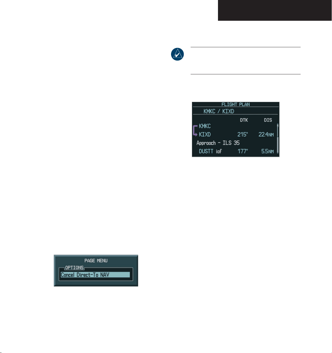
PRIMARY FLIGHT DISPLAY
To select a Direct-to from the Nearest Airports list:
1. Press the
Direct-to
key, then turn the
large FMS
knob to highlight the NRST field.
2. Turn the
small FMS
knob to display a selection
window showing the 25 nearest airports.
3. Turn the
FMS
knob to scroll through the list
and highlight the desired airport, then press
the
ENT
key.
ENT
4. Press the
key again to activate the direct-to.
To select a specific course to a waypoint:
1. Press the
Direct-to
key, then turn the
FMS
knobs
to select the desired destination waypoint, then
press the
2. Turn the
field. Turn the
course and press the
3. Press the
ENT
key.
large FMS
ENT
knob to highlight the ‘CRS’
FMS
knobs to select the desired
ENT
key.
key to activate the direct-to using
the selected course to the destination.
To cancel a Direct-to:
1. Press the
Direct-to
key, then press the
MENU
key to display the Direct-to Options Menu.
2. Press the
ENT
key to cancel direct-to navigation.
If a flight plan is still active, the G1000 resumes
flight plan navigation along the closest leg.
Flight Plan Window
ing the FPL key.
the PFD. The G1000 allows for the creation of up to 99
flight plans, with up to 31 waypoints in each flight plan.
lowing information:
NOTE: COM frequency and stored flight plans
cannot be loaded from the PFD Flight Plan
Window.
The Flight Plan Window is enabled/disabled by press-
Figure 2-52 Flight Plan Window
Flight plans can be created, edited and activated from
The Flight Plan Window on the PFD displays the fol
• Flight plan title
• Indication of the active leg (magenta line and arrow)
• Flight plan waypoints, including airport identifiers
• Leg distance
• Leg desired track
-
Figure 2-51 Cancel Direct-To NAV
Garmin G1000 Pilot’s Guide for the Diamond DA40190-00592-00 Rev. A
The following options are available for the Flight Plan
Window:
• Create New Flight Plan
• Activate Leg
• Store Flight Plan
• Invert Flight Plan
• Delete Flight Plan
• Load Departure
2-33
Page 62
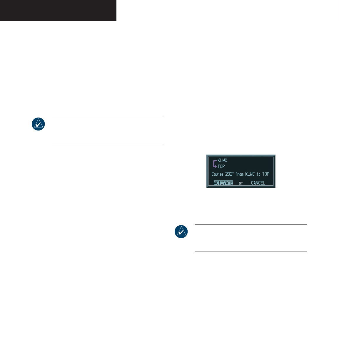
PRIMARY FLIGHT DISPLAY
• Load Arrival
• Load Approach
• Remove Departure
• Remove Arrival
• Remove Approach
• Closest Point of FPL
• Change Fields
• Restore Defaults
Create New Flight Plan
NOTE: An ‘active’ flight plan is created as soon as
the first two waypoints are entered on the Active
Flight Plan Page.
New flight plans can be created on the PFD and MFD.
The system can store up to 99 flight plans with up to 31
waypoints each.
To create a new flight plan:
1. Press the
key, then press the
FMS
knob to
FPL
activate the cursor. The waypoint field is now
highlighted.
2. Turn the
small FMS
knob to activate the
Waypoint Information window.
3. Turn the
the airport/waypoint and press the
FMS
knobs to enter the identifier of
ENT
key.
The system returns to the Flight Plan Window
with the cursor flashing on the next waypoint
field.
4. Repeat step 3 above to enter the identifier for
each additional waypoint.
Activate Leg
Activate leg selects the highlighted leg as the “active
leg” (the flight plan leg which is currently used for naviga
-
tion guidance).
To activate a flight plan along a specific
leg:
1. From the active Flight Plan Window, press
the
FMS
knob to active the cursor and turn
the
large FMS
knob to highlight the desired
destination waypoint.
MENU
2. Press the
press the
key, highlight ‘Activate Leg’ and
ENT
key. A confirmation window is
displayed with ‘ACTIVATE’ highlighted, press
the
ENT
key.
Figure 2-53 Activate Leg Confirmation Window
Store Flight Plan
NOTE: The active flight plan is erased when the
unit is turned off and when another flight plan
is activated.
When storing flight plans with an approach, departure, or arrival, the G1000 uses the waypoint information
from the current database to define the waypoints. If the
navigation database is changed or updated, the G1000 automatically updates the information if the procedure has
not been modified. If an approach, departure, or arrival
procedure is no longer available, the flight plan becomes
locked until the procedure is deleted from the flight plan
or until the correct navigation database is installed.
Garmin G1000 Pilot’s Guide for the Diamond DA40 190-00592-00 Rev. A2-34
Page 63
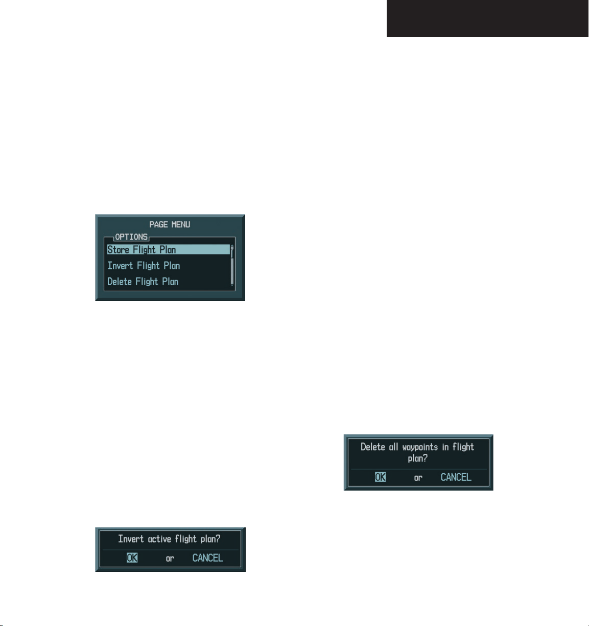
PRIMARY FLIGHT DISPLAY
To store a flight plan:
1. From the Flight Plan Window, once all the
waypoints have been entered, press the
MENU
key to display the page menu options.
FMS
2. Turn the
then press the
knob to select ‘Store Flight Plan’,
ENT
key. The Store Flight Plan
Window is displayed with ‘OK’ highlighted.
3. Press the
4. To cancel, turn the
‘CANCEL’ and press the
ENT
key to store the flight plan.
large FMS
Figure 2-54 Page Options Menu
knob to highlight
ENT
key.
Invert Flight Plan
Invert Flight Plan reverses the active flight plan. After
traveling along a flight plan, the pilot may wish to reverse
the route for navigation back to the original departure
point.
To activate an existing flight plan in
reverse:
Delete Flight Plan
The entire flight plan or selected waypoints within the
flight plan may be deleted.
To delete the entire flight plan:
1. From the Flight Plan Window, press the
key to display the page menu options.
2. Turn the
Plan’, then press the
FMS
knob to highlight ‘Delete Flight
ENT
key. The ‘Delete All
Waypoints in Flight Plan’ message is displayed
with ‘OK’ highlighted.
ENT
3. Press the
key to delete all waypoints in the
flight plan.
4. To cancel, turn the
‘CANCEL’ and press the
large FMS
ENT
knob to highlight
key.
To delete selected waypoints in the flight
plan:
1. From the Flight Plan Window, turn the
FMS
knob to select the desired waypoint.
CLR
2. Press the
key. The ‘Remove Waypoint
Name’ window is displayed with ‘OK’ high
lighted. Press the
ENT
key to delete the
selected waypoint.
3. To cancel, turn the
‘CANCEL’ and press the
large FMS
ENT
knob to highlight
key.
MENU
large
-
1. From the Flight Plan Window, press the
key to display the page menu options.
FMS
2. Turn the
Plan’, then press the
knob to highlight ‘Invert Flight
ENT
key. The flight plan
is now reversed and activated.
Figure 2-55 Invert Flight Plan Confirmation Window
Garmin G1000 Pilot’s Guide for the Diamond DA40190-00592-00 Rev. A
MENU
Figure 2--56 Delete Flight Plan Confirmation Window
2-35
Page 64
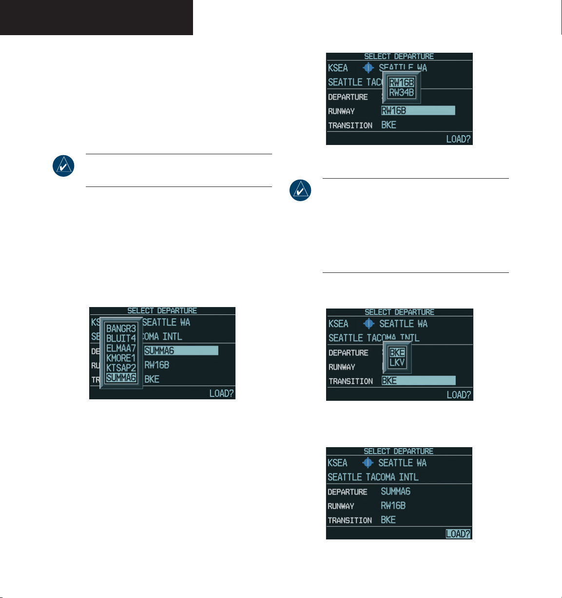
PRIMARY FLIGHT DISPLAY
Load Departure
Load Departure allows the pilot to select a published
standard instrument departure (SID) for the departure
airport, or replace the current departure with a new selec
tion. When using a direct-to, the G1000 uses the nearest
airport as a reference when displaying available depar
tures.
-
-
NOTE: The PROC key can also be used to load a
departure, an approach, or an arrival.
To select a departure for the departure
airport:
1. From the Flight Plan Window , press the
MENU
key to display the page menu options.
2. Turn the
ture’, then press the
FMS
knob to highlight ‘Load Depar-
ENT
key. A window
appears listing the available departures for the
departure airport.
Figure 2-57 Departure
3. Turn the
ture, then press the
FMS
knob to select the desired depar-
ENT
key.
4. A window may appear listing runways for the
FMS
departure. Turn the
desired runway, then press the
knob to select the
ENT
key. The
transition window is now displayed.
Figure 2-58 Departure Runway
NOTE: The runway window is not displayed for
every arrival. ‘ALL’ may appear in the runway
field, indicating that the arrival procedure applies
to all runways. For airports with parallel runways,
‘B’ may appear at the end of the runway designation to indicate that the arrival procedure applies
to both runways.
5. Turn the
tion waypoint, then press the
FMS
knob to select the desired transi-
ENT
Figure 2-59 Departure Transition
key.
6. With ‘LOAD?’ highlighted, press the
ENT
key.
Figure 2-60 Select Departure Window
Garmin G1000 Pilot’s Guide for the Diamond DA40 190-00592-00 Rev. A2-36
Page 65
PRIMARY FLIGHT DISPLAY
Load Arrival
Load Arrival allows the pilot to select a published stan-
dard terminal arrival route (STAR) for the destination air
-
port, or replace a current arrival with a new selection.
NOTE: The PROC key can also be used to load a
departure, an approach, or an arrival.
NOTE: When adding an arrival to an active flight
plan, the pilot may need to remove a duplicate
destination waypoint from the flight plan list.
To select an arrival for a direct-to or flight
plan destination airport:
1. From the Flight Plan Window, press the
MENU
key to display the page menu options.
2. Turn the
then press the
FMS
knob to highlight ‘Load Arrival’,
ENT
key. A window appears
listing the available arrivals for the destination
airport.
FMS
3. Turn the
then press the
knob to select the desired arrival,
ENT
key. A window appears
listing the available transitions for the arrival.
4. Turn the
tion waypoint, then press the
FMS
knob to select the desired transi-
ENT
key.
5. A window may appear listing runways for the
FMS
arrival. Turn the
runway, then press the
knob to select the desired
ENT
key.
Load Approach
Load Approach allows the pilot to select a published
instrument approach for the destination airport, or re
place the current approach with a new selection.
To select an approach for a direct-to or
flight plan destination airport:
1. From the Flight Plan Window, press the
key to display the page menu options.
2. Turn the
then press the
FMS
knob to highlight ‘Load Approach’,
ENT
key. A window appears listing the available approaches for the destina
tion airport.
FMS
3. Turn the
approach, then press the
appears listing the available transitions for the
knob to select the desired
ENT
key. A window
approach.
FMS
4. Turn the
tion or vectors, then press the
NOTE: The ‘Vectors’ option assumes that the pilot
will receive vectors from ATC to the final course
segment of the approach.
knob to select the desired transi-
ENT
key.
5. With ‘LOAD?’ highlighted, press the
to load the approach.
6. To activate the approach, turn the
knob to highlight ‘ACTIVATE?’, then press the
ENT
key.
-
MENU
-
ENT
key
large FMS
NOTE: The runway window is not displayed for
every arrival. ‘ALL’ may appear in the runway
field, indicating that the arrival procedure applies
to all runways. For airports with parallel runways,
‘B’ may appear at the end of the runway designation to indicate that the arrival procedure applies
to both runways.
6. With ‘LOAD?’ highlighted, press the
Garmin G1000 Pilot’s Guide for the Diamond DA40190-00592-00 Rev. A
ENT
key.
NOTE: ‘LOAD’ adds the approach to the flight
plan without immediately using the approach
for navigation guidance. This allows the pilot to
continue navigating the original flight plan until
cleared for the approach, but keeps the approach
available for quick activation when needed.
‘ACTIVATE’ adds the approach to the flight plan
and begins navigating the approach course.
2-37
Page 66
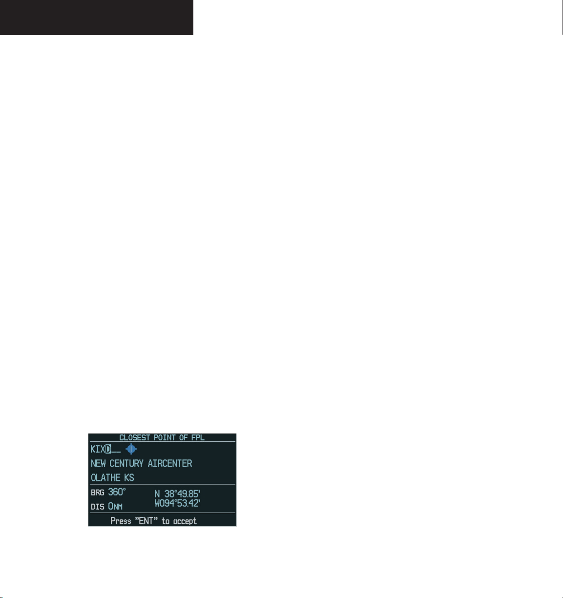
PRIMARY FLIGHT DISPLAY
Remove Departure, Arrival, or Approach
Remove Departure, Arrival, or Approach deletes the
current standard instrument departure (SID), terminal ar
rival route (STAR), or selected approach from the active
flight plan.
To remove a departure, an arrival, or an
approach from a direct-to or active flight
plan:
1. From the Flight Plan Window, press the
MENU
key to display the page menu options.
FMS
2. Turn the
knob to highlight ‘Remove Departure’, ‘Remove Arrival’, or ‘Remove Approach’,
then press the
ENT
key. A confirmation window
appears listing the procedure that is about to
be removed, with ‘OK’ highlighted.
ENT
3. Press the
4. To cancel, turn the
‘CANCEL’, then press the
key to remove the procedure.
large FMS
knob to highlight
ENT
key.
Closest Point of FPL
Closest Point of FPL calculates the bearing and clos
est distance at which a flight plan passes from a reference waypoint. It may also be used to create a new user
waypoint along the flight plan at the location closest to a
chosen reference waypoint.
To determine the closest point along the
active flight plan to a selected waypoint:
1. From the Flight Plan Window, press the
key to display the page menu options.
FMS
2. Turn the
of FPL’, then press the
knob to highlight ‘Closest Point
ENT
key. A window
appears with the reference waypoint field
highlighted.
FMS
reference waypoint, then press the
3. Turn the
knobs to enter the identifier of the
ENT
G1000 displays the bearing (BRG) and distance
(DIS) to the closest point along the flight plan,
from the selected reference waypoint.
4. To create a user waypoint at this location and
add it to the flight plan, press the
ENT
name for the new user waypoint is derived from
the identifier or the reference waypoint.
Change Fields
Change Fields allows the pilot to select the desired
data items to be displayed on the Flight Plan Window.
The user-selectable data fields can be changed to display
the following information:
• Cumulative Distance (CUM)
• Distance (DIS)
• Desired Track (DTK)
• En route Safe Altitude (ESA)
• Estimated Time of Arrival (ETA)
• Estimated Time En route (ETE)
MENU
key. The
key. The
Figure 2-61 Closest Point of FPL Window
Garmin G1000 Pilot’s Guide for the Diamond DA40 190-00592-00 Rev. A2-38
Page 67
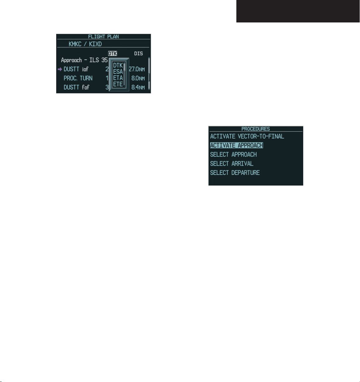
Figure 2-62 Change Fields on Flight Plan
To change a data field on the Flight Plan
Window:
1. From the Flight Plan Window, press the
MENU
key to display the page menu options.
2. Turn the
then press the
FMS
knob to highlight ‘Change Fields’,
ENT
key. The cursor flashes on
one of the data fields.
3. Turn the
large FMS
knob to highlight the field
to be changed.
4. Turn the
small FMS
knob to display a window
with optional data items.
5. Turn the
item, then press the
FMS
FMS
knob to select the desired data
ENT
key. Press the
knob to remove the cursor.
small
PRIMARY FLIGHT DISPLAY
Procedures Window
The Procedures Window is enabled and disabled by
pressing the PROC key. The following options are available from the Procedures Window:
• Activate Vector-To-Final
• Activate Approach
• Select Approach
• Select Arrival
• Select Departure
Figure 2-63 Procedures Window
Select Approach
Select Approach allows the pilot to choose a published
instrument approach for the destination airport, or replace
the current approach with a new selection.
Restore Defaults
Restore Defaults returns all data fields to the factory
default settings.
To restore factory default settings for data
fields on the Flight Plan Window:
1. From the Flight Plan Window, press the
key to display the page menu options.
FMS
2. Turn the
Defaults’, then press the
knob to highlight ‘Restore
ENT
key.
Garmin G1000 Pilot’s Guide for the Diamond DA40190-00592-00 Rev. A
MENU
To select an approach for a direct-to or
flight plan destination airport:
PROC
1. From an active flight plan, press the
key
to display the Procedures options window.
2. Turn the
Approach’, then press the
large FMS
knob to highlight ‘Select
ENT
key. A window
appears listing the available approaches for
the destination airport.
2-39
Page 68
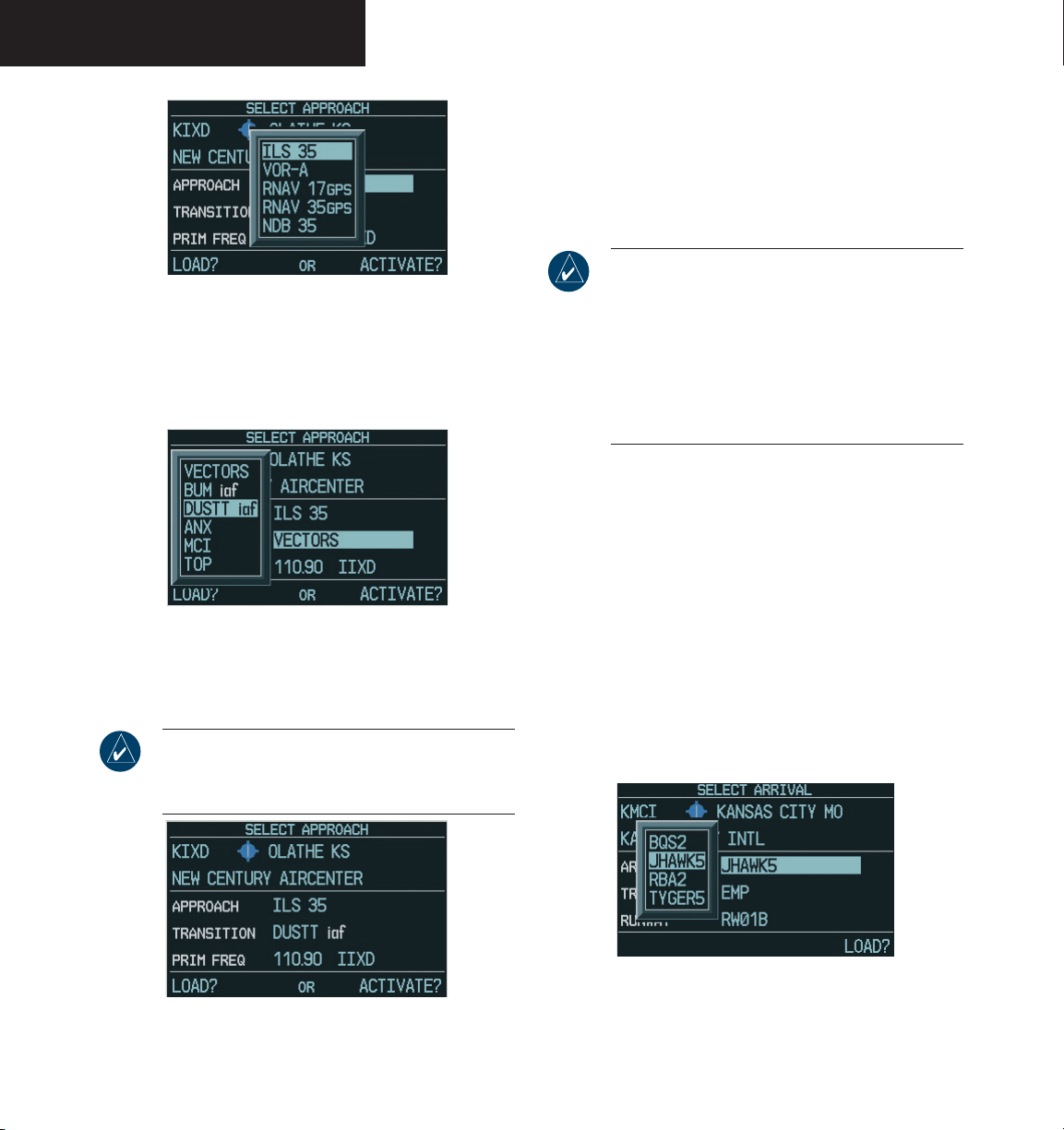
PRIMARY FLIGHT DISPLAY
Figure 2-64 Approach
3. Turn the
approach, then press the
FMS
knob to select the desired
ENT
key. A window
appears listing the available transitions for the
approach.
Figure 2-65 Approach Transition
4. Turn the
tion or vectors, then press the
NOTE: The ‘Vectors’ option assumes that the pilot
will receive vectors from ATC to the final course
segment of the approach.
FMS
knob to select the desired transi-
ENT
key.
5. With ‘LOAD?’ highlighted, press the
ENT
key
to load the approach.
6. To activate the approach, turn the
large FMS
knob to highlight ‘ACTIVATE?’, then press the
ENT
key.
NOTE: ‘LOAD’ adds the approach to the flight
plan without immediately using the approach
for navigation guidance. This allows the pilot to
continue navigating the original flight plan until
cleared for the approach, but keeps the approach
available for quick activation when needed.
‘ACTIVATE’ adds the approach to the flight plan
and begins navigating the approach course.
Select Arrival
Select Arrival allows the pilot to choose a published
standard terminal arrival route (STAR) for the destination
airport, or replace a current arrival with a new selection.
To select an arrival for a direct-to or flight
plan destination airport:
PROC
1. From an active flight plan, press the
key
to display the Procedures options window.
2. Turn the
Arrival’, then press the
large FMS
knob to highlight ‘Select
ENT
key. A window
appears listing the available arrivals for the
destination airport.
Figure 2-66 Select Approach Window
Garmin G1000 Pilot’s Guide for the Diamond DA40 190-00592-00 Rev. A2-40
Figure 2-67 Arrival
Page 69
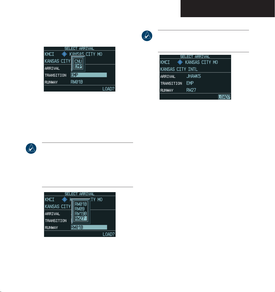
PRIMARY FLIGHT DISPLAY
3. Turn the
then press the
FMS
knob to select the desired arrival,
ENT
key. A window appears
listing the available transitions for the arrival.
Figure 2-68 Arrival Transition
4. Turn the
tion, then press the
FMS
knob to select the desired transi-
ENT
key.
5. A window may appear listing runways for the
FMS
arrival. Turn the
runway, then press the
NOTE: The runway window is not displayed for
every arrival. ‘ALL’ may appear in the runway
field, indicating that the arrival procedure applies
to all runways. For airports with parallel runways,
‘B’ may appear at the end of the runway designa
tion to indicate that the arrival procedure applies
to both runways.
Figure 2-69 Arrival Runway
6. With ‘LOAD?’ highlighted, press the
knob to select the desired
ENT
key.
ENT
key.
NOTE: When adding an arrival to an active flight
plan, the pilot may need to remove a duplicate
destination waypoint from the flight plan list.
Figure 2-70 Select Arrival Window
Select Departure
Select Departure allows the pilot to choose a published
standard instrument departure (SID) for the departure
airport, or replace the current departure with a new selec
tion. When using a direct-to, the G1000 uses the nearest
airport as a reference when displaying available departures.
-
To select a departure for the departure
airport:
1. From an active flight plan, press the
to display the Procedures options window.
2. Turn the
Departure’, then press the
large FMS
knob to highlight ‘Select
ENT
key. A window
appears listing the available departures for the
departure airport.
FMS
3. Turn the
ture, then press the
knob to select the desired depar-
ENT
key.
4. A window may appear listing runways for the
departure. Turn the
desired runway, then press the
FMS
knob to select the
ENT
transition window is now displayed.
PROC
key
key. The
-
Garmin G1000 Pilot’s Guide for the Diamond DA40190-00592-00 Rev. A
2-41
Page 70

PRIMARY FLIGHT DISPLAY
NOTE: The runway window is not displayed for
every departure. ‘ALL’ may appear in the runway
field, indicating that the departure procedure
applies to all runways. For airports with parallel
runways, ‘B’ may appear at the end of the runway
designation to indicate that the departure proce
dure applies to both runways.
5. Turn the
tion, then press the
FMS
knob to select the desired transi-
ENT
key.
6. With ‘LOAD?’ highlighted, press the
Activate Approach
Activate Approach allows the pilot to activate the ap
proach when ready to begin navigating the approach
course (cleared for the approach).
To activate the approach for a direct-to or
flight plan destination airport:
ENT
key.
Activate Vector-To-Final
Activate Vector-To-Final allows the pilot to activate the
final course segment of the approach. This option assumes
that the pilot will receive vectors from ATC to the final ap
proach fix (FAF) and provides guidance to intercept the
final course, before reaching the FAF.
-
To activate the approach with vectors to
final:
1. From an active flight plan, press the
to display the Procedures options window.
FMS
2. Turn the
To-Final’, then press the
knob to highlight ‘Activate Vector-
ENT
key.
-
PROC
-
key
1. From an active flight plan, press the
to display the Procedures options window.
2. Turn the
large FMS
Approach’, then press the
knob to highlight ‘Activate
ENT
key.
Garmin G1000 Pilot’s Guide for the Diamond DA40 190-00592-00 Rev. A2-42
PROC
key
Page 71
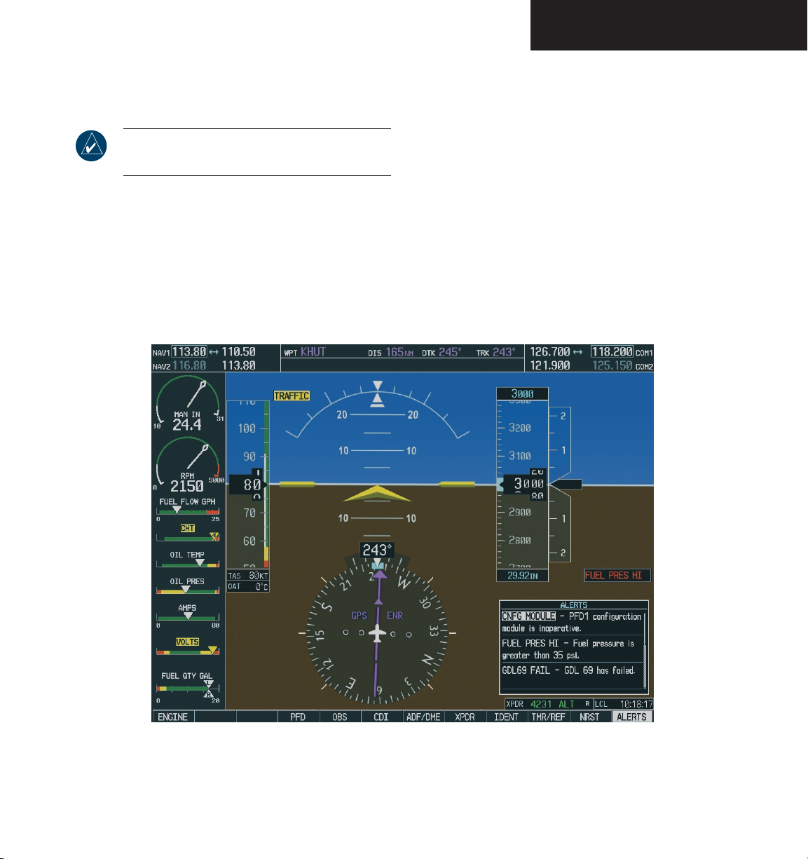
PRIMARY FLIGHT DISPLAY
2.7 REVERSIONARY MODE
NOTE: Refer to the System Overview for a
detailed description of Reversionary mode.
The PFD is designed to enter a reversionary (backup)
mode based on automatic fault monitoring and detection internal switching. Reversionary mode can also be
activated by manually pressing a dedicated DISPLAY
BACKUP button at the bottom of the Audio Panel (refer
to Audio Panel section).
In reversionary mode, the computer display units
(CDUs) are re-configured to present the PFD symbology
together with the engine parameters (engine parameters
are incorporated on the left side of the display). Reversionary PFD parameters are presented in the same format
as prior to re-configuration. In the event of a display failure, the pilot loses one NAV, one COM, and GPS:
• PFD failure – NAV1, COM1, and GPS1 are lost
• MFD failure – NAV2, COM2, and GPS2 are lost
Figure 2-71 PFD Reversionary Mode
Garmin G1000 Pilot’s Guide for the Diamond DA40190-00592-00 Rev. A
2-43
Page 72
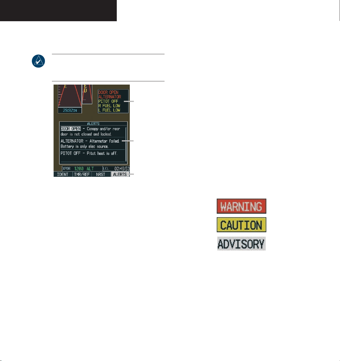
PRIMARY FLIGHT DISPLAY
2.8 ALERTS AND ANNUNCIATIONS
NOTE: For a detailed description of all annunciations and alerts, refer to the Annunciations and
Alerts section.
Annunciation
Window
Alerts Window
Alerts Softkey
Figure 2-72 G1000 Alerting System
Annunciation
ANNUNCIATION WINDOW
The Annunciation window appears to the right of the
Vertical Speed Indicator when a WARNING or CAUTION
alert is issued. Warning alerts are displayed in red and
caution alerts are displayed in yellow. When new alerts
appear, they are displayed with a separate white line at
the top of the Annunciation window, regardless of priority.
Once they are acknowledged, they are sequenced based
on priority.
SOFTKEY ANNUNCIATIONS
The ALERTS softkey label changes to display the appropriate annunciation when an alert is issued. The annunciation flashes and the appropriate aural alert sounds
until acknowledged by depressing the softkey. The softkey then reverts to the ALERTS label and, when pressed
again, displays a description of the annunciation in the
Alerts Window.
ALERTS WINDOW
The Alerts Window appears in the lower right corner
of the PFD when a warning, caution, or advisory alert
message occurs. This window allows system alert messages to be displayed simultaneously. The FMS knobs can
be used to scroll through the alerts. Pressing the ALERTS
softkey enables/disables the Alerts Window.
Alert messages are provided to make the pilot aware
of G1000 system problems or status and may not require
pilot action. An alert message is accompanied by a flash
ing white ALERTS softkey label to alert the pilot. Press-
ing the ALERTS softkey acknowledges the presence of an
alert and opens the Alerts Window.
Garmin G1000 Pilot’s Guide for the Diamond DA40 190-00592-00 Rev. A2-44
-
Figure 2-73 Alerts Softkey Annunciations
Warnings are time-critical and require immediate pilot
attention. A flashing “WARNING” softkey annunciation
and an aural tone (single chime every two seconds) are
used to alert the pilot of any warnings. The aural tone
and flashing “WARNING” annunciator continue until
acknowledged by the pilot (by pressing the WARNING
softkey).
Page 73
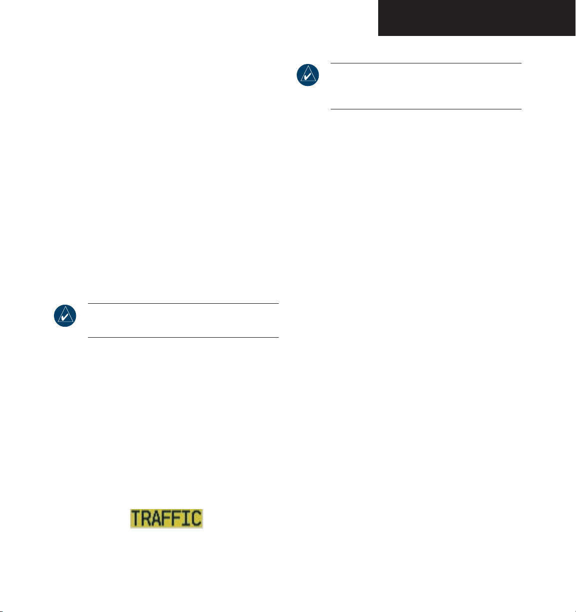
Caution indicates the existence of abnormal conditions on the aircraft that may require pilot intervention.
A flashing “CAUTION” softkey annunciation and a single
aural tone (one chime) are used to alert the pilot of any
cautions. The flashing “CAUTION” annunciator contin
ues to flash until acknowledged by the pilot (by pressing
the CAUTION softkey).
PRIMARY FLIGHT DISPLAY
NOTE: If a second TA appears or if the TAs displayed decrease and then increase, new aural
and visual alerts are generated.
An advisory provides general information to the pi
lot that may not need immediate attention. A flashing
“ADVISORY” softkey annunciation (no aural tone) is used
to alert the pilot of any message advisories. The flashing “ADVISORY” annunciator continues to flash until
acknowledged by the pilot (by pressing the ADVISORY
softkey).
TRAFFIC ANNUNCIATION
NOTE: Refer to the Appendix for more details
about Traffic Information Service (TIS).
The G1000 system displays Traffic Information Service
(TIS) traffic on the PFD Inset Map and the MFD Navigation Map Page. When a traffic advisory (TA) is detected,
the following automatically occurs:
• The Inset Map is enabled and displays the traffic
• A single “TRAFFIC” aural alert is generated
• A flashing black-on-yellow “TRAFFIC” annuncia
tion appears to the top left of the Attitude indicator (see Figure 2-2) for five seconds and remains
displayed until no TAs are detected in the area
-
Figure 2-74 Traffic Annunciation
Garmin G1000 Pilot’s Guide for the Diamond DA40190-00592-00 Rev. A
2-45
2-45
Page 74

PRIMARY FLIGHT DISPLAY
This page intentionally left blank
Garmin G1000 Pilot’s Guide for the Diamond DA40 190-00592-00 Rev. A2-46
Page 75

G1000
NAV/COM
TM
Page 76

190-00592-00 Rev. AGarmin G1000 Pilot’s Guide for the Diamond DA40
Page 77
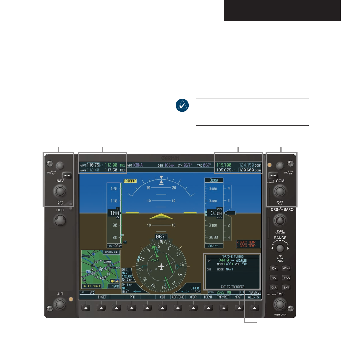
NAV/COM
3.1 NAV/COM INTRODUCTION
The NAV/COM frequency controls and windows are
located in the top corners of the Primary Flight Display
(PFD) and Multi Function Display (MFD). The NAV
controls and NAV frequency window are located on the
left side, the COM controls and COM frequency window
are on the right. The ADF/DME Tuning window is located
in the lower right corner on the PFD, as shown in the
figure below.
NAV
Controls
NAV Frequency Window COM Frequency Window
The NAV/COM interface includes:
• Windows and fields
• Radio selection
• Tuning box
• Frequency Transfer Arrows
• Radio status indications
• Controls
NOTE: Information on the optional ADF and DME
radios as well as the ADF/DME Tuning window is
presented later in this document.
COM
Controls
Figure 3-1 G1000 VHF NAV/COM Interface (PFD)
190-00592-00 Rev. A Garmin G1000 Pilot’s Guide for the Diamond DA40
ADF/DME Tuning Window
3-1
Page 78
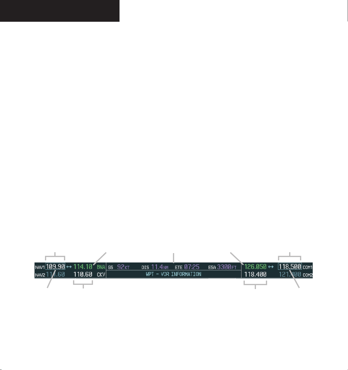
NAV/COM
WINDOWS AND FIELDS
The NAV and COM Frequency windows are located
at the top of the display on either side of the Navigation
Status bar on both the PFD and the MFD.
• The NAV
of the Navigation Status bar.
• The COM
right of the Navigation Status bar.
Each radio frequency window is composed of two
fields, a
standby field and an active field.
• In the NAV Frequency window, the active frequency
is on the right side, the standby frequency is on the
left.
• In the COM Frequency window, the active frequency
is on the left side, the standby frequency is on the
right.
Frequency window is displayed to the left
Frequency window is displayed to the
RADIO SELECTION
Frequencies in the active window are displayed in
either green or white.
• An active COM frequency is displayed in green
indicating that the COM radio is selected on the
audio panel (COM1 MIC or COM2 MIC keys).
White numbers indicate that the radio is not
selected.
• An active NAV frequency is displayed in green
indicating the NAV radio is selected for navigation
on the HSI. NAV radio selection is made with the
PFD CDI softkey.
• NAV1 selected: a single green arrow with ‘VOR1’ or
‘LOC1’ displayed on the HSI.
• NAV2 selected: a double green arrow with ‘
or ‘LOC2’ displayed on the HSI.
• Both active NAV frequencies displayed in white
indicate that GPS is in use.
VOR2’
Standby NAV
Frequency Field
Tuning Box
Selected NAV
Active NAV
Frequency Field
Radio
Navigation Status Bar
Figure 3-2 Frequency Fields
Selected COM
Radio
Frequency Field
Active COM
Standby COM
Frequency Field
Tuning Box
190-00592-00 Rev. AGarmin G1000 Pilot’s Guide for the Diamond DA403-2
Page 79
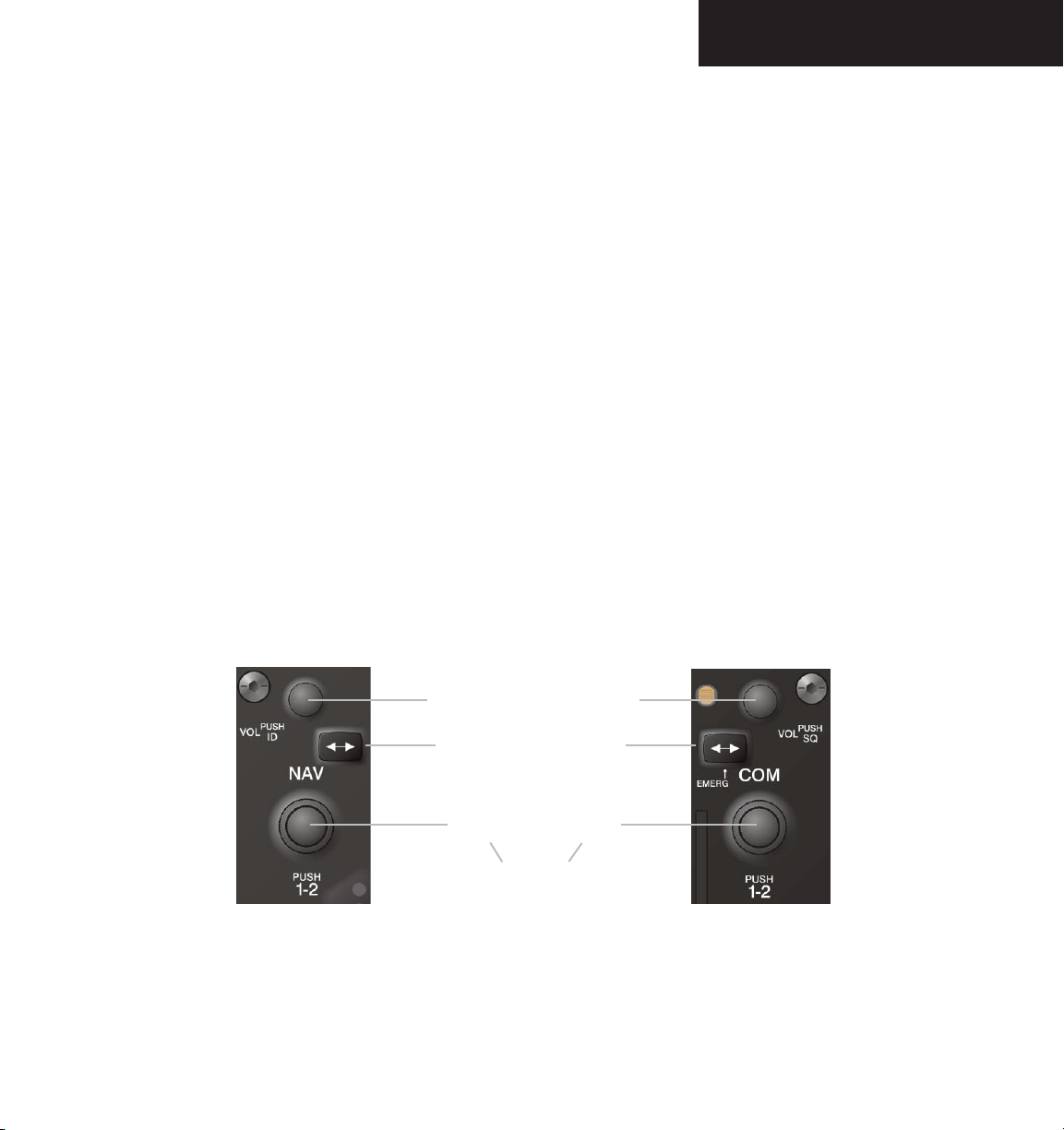
NAV/COM
CONTROLS
The NAV Frequency window is controlled by knobs
and keys on the left, the COM Frequency window by
knobs and keys on the right.
The NAV controls:
• VOL/PUSH ID knob
– Turn to adjust the NAV radio volume level.
– Press to turn the Morse code ID ON and OFF.
• Frequency Transfer key
– Press to transfer the NAV frequencies between
the active and standby fields.
• Dual NAV tuning knob
– Turn to tune a NAV frequency in the NAV
tuning box (large knob for MHz; small knob
for kHz).
– Press to transfer the NAV tuning box between
the NAV1 and NAV2 radios.
The COM controls:
• VOL/PUSH SQ knob
– Turn to adjust the COM radio volume.
– Press to turn automatic squelch ON and OFF.
• Frequency Transfer key
– Press to transfer the COM frequencies between
the active and standby fields.
– Press and hold for two seconds to tune the
emergency frequency (121.500 MHz) in the
active COM field.
• Dual COM tuning knob
– Turn to tune a COM frequency in the COM
tuning box (large knob for MHz; small knob
for kHz).
– Press to transfer the COM tuning box between
the COM1 and COM2 radios.
NAV Controls COM Controls
VOL/PUSH
ID Knob
Frequency Transfer Keys
Dual NAV
Knob
• Turn to tune desired
frequencies.
• Press to change tuning box
positions.
Figure 3-3 NAV/COM Controls
190-00592-00 Rev. A Garmin G1000 Pilot’s Guide for the Diamond DA40
VOL/PUSH
SQ Knob
Dual COM
Knob
3-3
Page 80
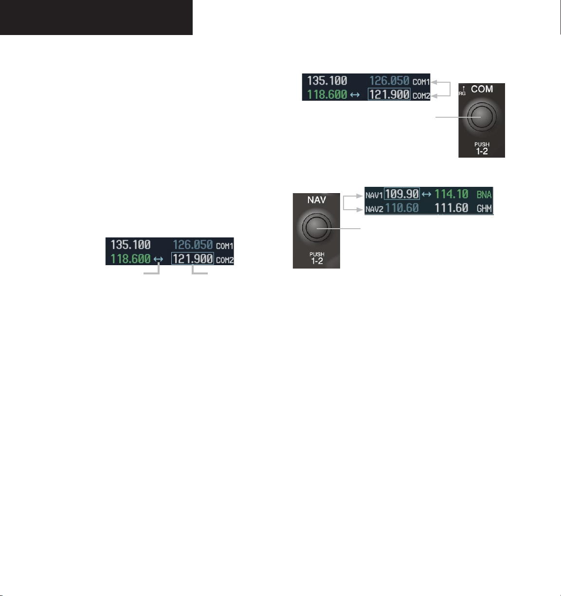
NAV/COM
TUNING BOX
A light blue tuning box is displayed around the radio
standby frequency window, on both the PFD and MFD.
Pressing the small COM or NAV knob transfers the tuning
box back and forth between the two windows.
Pushing the small COM knob switches the
tuning box from one COM radio to the other.
Frequencies located in the standby window are
displayed in either white or gray.
• The standby frequency appearing in the tuning box
is white.
• The other standby frequency is gray.
Frequency Transfer Arrow
Figure 3-4 Frequency Transfer Arrow and Tuning Box
Tuning Box
SWITCHING BETWEEN RADIOS
Pressing the small COM or NAV knob transfers the
tuning box between the radio frequency windows.
When a different COM transceiver is selected on the
audio panel, the COM frequency tuning box highlights
the frequency on both the PFD and MFD.
When a different NAV radio is selected on the HSI, the
NAV frequency tuning box highlights the frequency on
the PFD and MFD. The NAV frequency tuning box does
not change when GPS mode is selected.
Figure 3-5 Switching COM Radios
Pushing the small NAV knob switches the
tuning box from one NAV radio to the other.
Figure 3-6 Switching NAV Radios
MANUALLY TUNING A FREQUENCY
The dual COM and dual NAV frequency knobs are
used for manual COM and NAV radio tuning. The
frequencies are tuned in the standby field.
• The MHz frequency digits are tuned with the large
COM and NAV knobs.
• The kHz frequency digits are tuned with the small
COM and NAV knobs.
Turning the knobs clockwise increases frequency.
Turning the knobs counterclockwise decreases frequency.
190-00592-00 Rev. AGarmin G1000 Pilot’s Guide for the Diamond DA403-4
Page 81
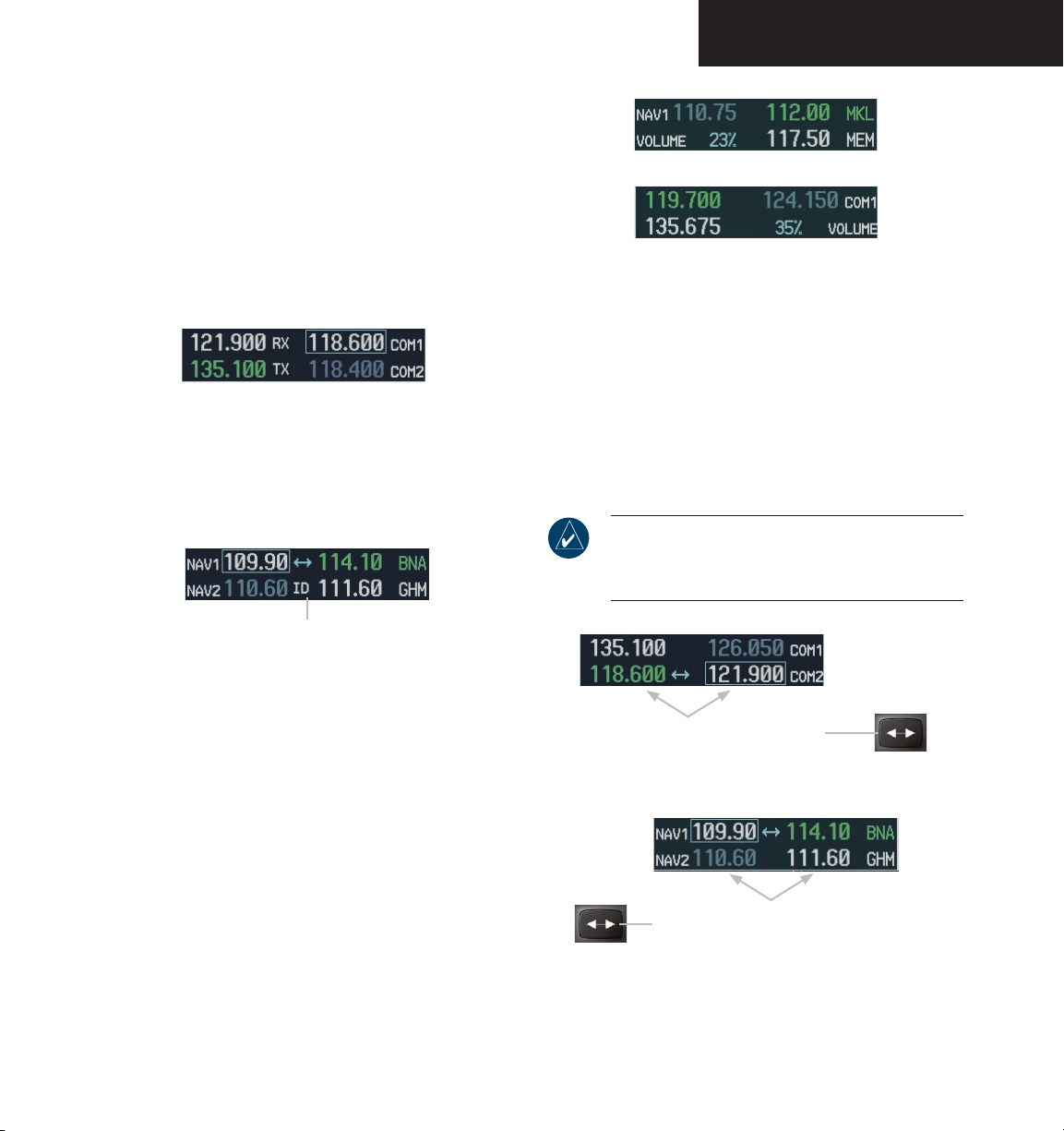
RADIO INDICATORS
• RX – During COM signal reception, a white RX
appears by the active COM frequency.
• TX – During COM transmission, a white TX
appears by the active COM frequency replacing the
Frequency Transfer Arrow.
Figure 3-7 COM Radio Status Indications
• ID – When the Morse code identifier is ON for a
NAV radio, a white ID appears to the left of the
active NAV frequency.
NAV/COM
Figure 3-9 COM and NAV Volume Levels
FREQUENCY TRANSFER ARROW
The Frequency Transfer Arrow is displayed between
the COM and NAV active and standby frequencies for
the active radio. Pressing the Frequency Transfer
transfers the frequencies. Pressing the small COM or
NAV knob transfers the frequency tuning box and the
Frequency Transfer Arrow between the radios.
NOTE: When a COM signal is received or
transmitted, the Frequency Transfer Arrow is
replaced by a white RX or TX
indication.
key
The Morse code identifier is
ON for the GHM VOR.
Figure 3-8 ID Indication
VOLUME
Pressing the COM Frequency Transfer
key transfers the COM frequencies.
Radio volume level can be adjusted from 0 to 100%
using the VOL/PUSH SQ knob for COM or VOL/PUSH
ID knob for NAV. Turning the knob clockwise increases
volume, counterclockwise decreases volume.
When adjusting, the level is displayed in place of the
standby frequencies. Volume level indication remains for
two seconds after the change.
Figure 3-10 Transferring COM and NAV Frequencies
190-00592-00 Rev. A Garmin G1000 Pilot’s Guide for the Diamond DA40
Pressing the NAV Frequency Transfer
key transfers the NAV frequencies.
3-5
Page 82
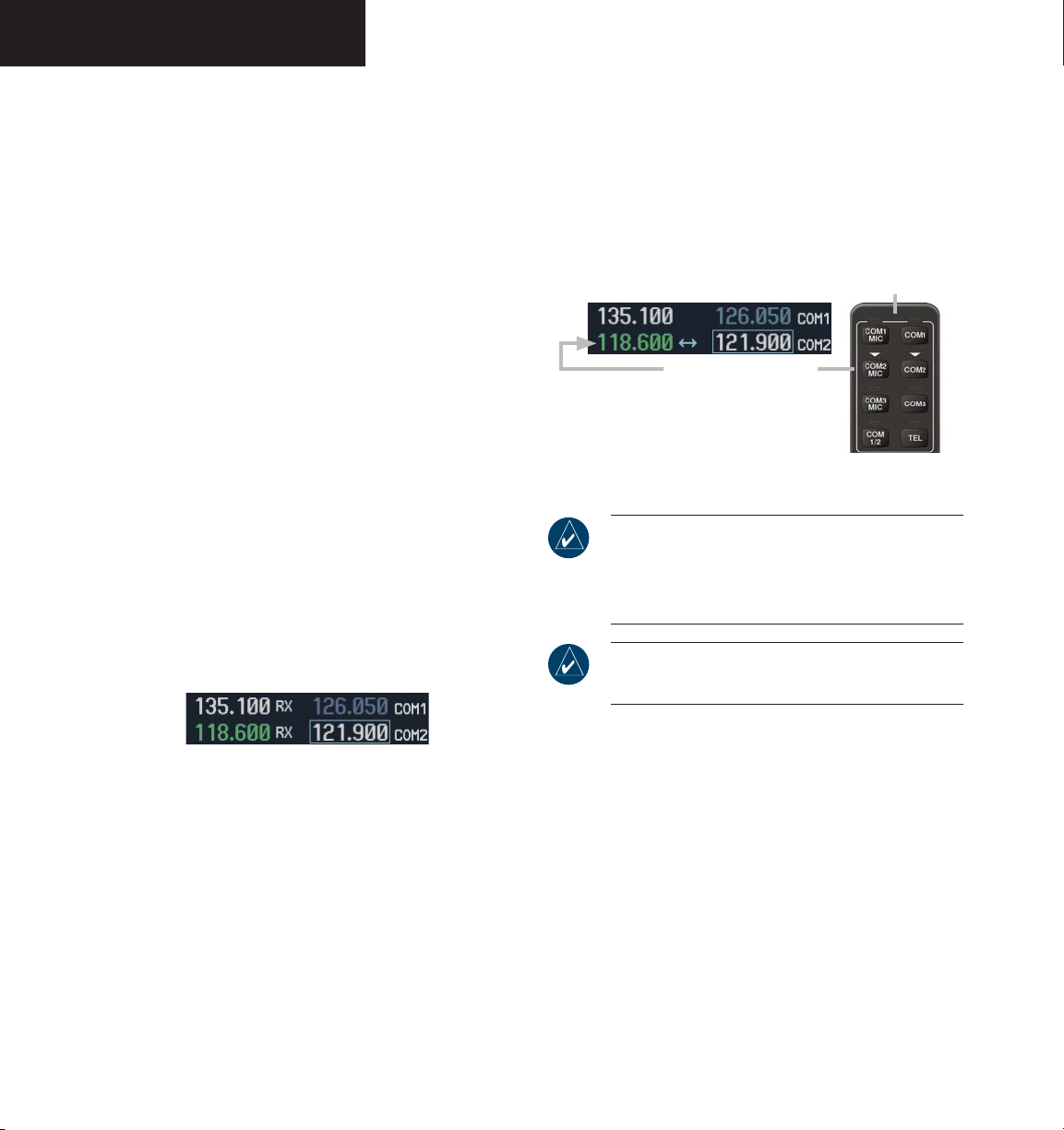
NAV/COM
3.2 COM OPERATION
FREQUENCY SPACING
The G1000 COM radios can tune either 25 kHz spacing
(118.000 to 136.975 MHz) or 8.33 kHz spacing (118.000
to 136.990 MHz) for 760-channel or 3040-channel
configuration.
COM channel spacing is configured through the MFD
on the System Setup Page of the AUX Page group.
AUTOMATIC SQUELCH
Automatic squelch quiets unwanted static noise when
no audio signal is received, while still providing reasonable
sensitivity to weak COM signals. To disable auto squelch,
press the VOL/PUSH SQ knob.
When automatic squelch is disabled, COM audio
reception is always on. Continuous static noise is heard
over the speaker and phones, and an
appears on the display.
RX indication
SELECTING A COM RADIO
The desired COM radio is selected using the COM
MIC keys on the audio panel. When the COM MIC key
is annunciated, the corresponding active COM frequency
is displayed in green in the COM Frequency window.
Top portion of the
audio panel
COM radio selection is
performed via the
Figure 3-12 Selecting a COM Radio
NOTE: When PA mode is selected on the audio
panel, the COM MIC annunciator is no longer lit
and the active COM frequency changes to white,
indicating that there is no COM activity.
NOTE: Refer to the Audio Panel section for more
details on transceiver selection.
audio
panel.
Figure 3-11 Overriding Automatic Squelch
To enable automatic squelch, press the VOL/PUSH
SQ knob again.
190-00592-00 Rev. AGarmin G1000 Pilot’s Guide for the Diamond DA403-6
Page 83
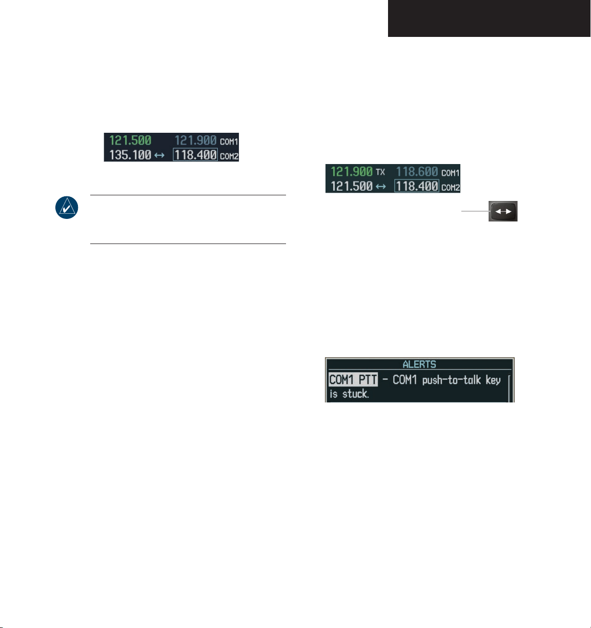
NAV/COM
EMERGENCY FREQUENCY (121.500 MHZ)
In case of a COM system tuning failure, the emergency
frequency (121.500 MHz) is automatically tuned in the
radio in which the tuning failure occurred.
Figure 3-13 COM Tuning Failure
NOTE: In case of a dual display failure, the COM
radios are automatically tuned to the emergency
frequency (121.500 MHz).
QUICK-TUNING AND ACTIVATING
121.500 MHZ
Pressing and holding the COM Frequency Transfer
key for two seconds automatically loads the emergency
COM frequency (121.500 MHz) in the active field of the
active COM radio (the one with the transfer arrow).
Press for two seconds to load 121.5 MHz.
Figure 3-14 Quickly Tuning 121.500 MHz
STUCK MICROPHONE
If the push-to-talk (PTT) switch becomes stuck, the
COM transmitter stops transmitting after 35 seconds of
continuous operation. An alert appears on the PFD to
advise the crew of a stuck microphone.
Figure 3-15 Stuck Microphone Alert
The COM1 MIC or COM2 MIC key annunciator on
the audio panel continues to blink as long as the PTT
switch remains stuck.
190-00592-00 Rev. A Garmin G1000 Pilot’s Guide for the Diamond DA40
3-7
Page 84
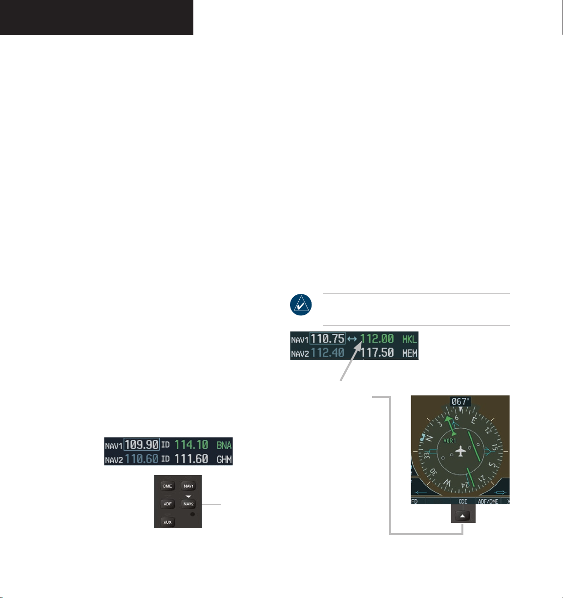
NAV/COM
3.3 NAV OPERATION
FREQUENCY RANGE
NAV RADIO SELECTION FOR NAVIGATION
pressing the CDI softkey located on the PFD. The three
navigation modes that can be selected are:
The NAV radios receive in the VOR/ILS frequency range
of 108.00 to 117.95 MHz with 50 kHz spacing. The NAV
Frequency window displays the following information:
• NAV1 and NAV2 active and standby frequencies
• NAV1 and NAV2 identifier indication (if the Morse
code identifier is received by the system)
• Color-coded indication of the selected NAV radio
• Morse code identifier status
MORSE CODE IDENTIFIER
Press the VOL/PUSH ID knob to turn the Morse code
identifier ON and OFF. When the identifier is ON, a
white ID indication appears to the left of the active NAV
frequency, and the Morse code is heard on the NAV audio.
The VOR/LOC Morse code identifier is displayed next to
the active NAV frequency.
The desired NAV radio is selected for navigation by
• VOR1 (or LOC1) – If NAV1 is selected, a single
green arrow (shown) labeled either ‘VOR1’ or
‘LOC1’ is displayed on the HSI and the active NAV1
frequency is displayed in green.
• VOR2 (or LOC2) – If NAV2 is selected, a double
green arrow (not shown) labeled either ‘VOR2’ or
‘LOC2’ is displayed on the HSI and the active NAV2
frequency is displayed in green.
• GPS – If GPS mode is selected, a single magenta
arrow (not shown) appears on the HSI and neither
NAV radio is selected.
NOTE: In GPS mode, both active NAV frequencies
are displayed in white.
When the identifier is OFF, the ID indication disappears
and the Morse code is off.
NAV audio is available with the ID filtered out for
listening to HIWAS and FSS transmissions on VOR
stations.
NAV2 radio is selected on the
audio panel. The Morse code
identifier for the GHM VOR
can be heard.
Figure 3-16 Morse Code Identifier Audio
NAV section
of the audio
panel
NAV radio selection is
performed via the
softkey.
CDI
Figure 3-17 Selecting a NAV Radio
190-00592-00 Rev. AGarmin G1000 Pilot’s Guide for the Diamond DA403-8
Page 85
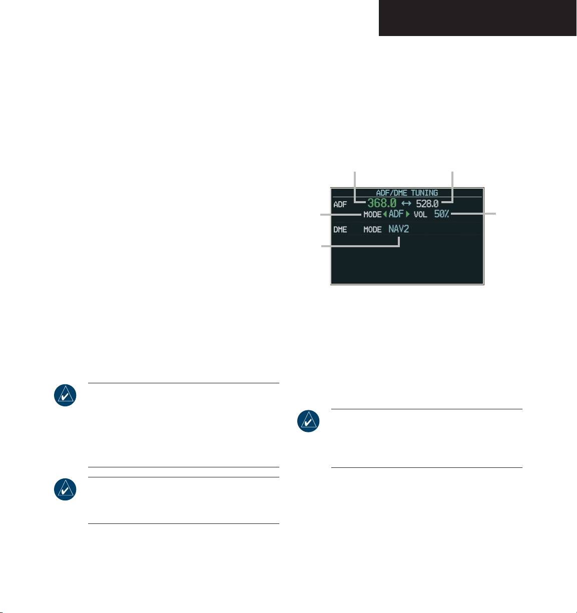
NAV/COM
3.4 OPTIONAL RADIOS
OVERVIEW
Optionally, the G1000 system can support up to two
(2) remotely-mounted Becker RA 3502 ADF receivers and
up to two (2) remotely-mounted Honeywell KN 63 DME
transceivers.
• The Becker RA 3502 ADF receiver operates in the
190.0 kHz to 1799.5 kHz frequency band with 0.5
kHz channel spacing.
• The Honeywell KN 63 is a 200-channel, 100-watt,
all-solid-state digital DME transceiver that provides
distance information to the G1000 system.
ADF/DME TUNING WINDOW
Tuning of the ADF and DME radios is performed via
the ADF/DME Tuning window. The ADF/DME Tuning
window is an Auxiliary window that is located to the right
of the HSI on the PFD. Pressing the ADF/DME softkey
transfers the ADF/DME Tuning window ON and OFF.
NOTE: Depending upon the nature of the optional
NAV radios installed, the Radio Tuning window
is entitled either ‘ADF TUNING’, ‘DME TUNING’,
or ‘ADF/DME TUNING’, and its associated softkey
is entitled either ‘ADF’, ‘DME’, or ‘ADF/DME’,
respectively.
The following information is displayed in the ADF/
DME Tuning window:
• Active and standby ADF frequencies
• ADF receiver mode
• ADF receiver volume
• DME tuning mode
Active ADF Frequency Standby ADF Frequency
ADF
Mode
DME
Mode
Figure 3-18 ADF/DME Tuning Window
ADF
Volume
Turning the large FMS knob moves the selection
cursor through the various editable fields (i.e., standby
ADF frequency, ADF receiver mode, ADF radio volume
and DME tuning mode), while pressing the FMS knob
activates/deactivates the selection cursor in the ADF/DME
Tuning window.
NOTE: When the ADF/DME Tuning window is
turned on (i.e., displayed), the selection cursor
is automatically activated in the window and is
displayed over the standby ADF frequency field.
NOTE: When another Auxiliary window is turned
on, the ADF/DME Tuning window is removed from
the PFD.
190-00592-00 Rev. A Garmin G1000 Pilot’s Guide for the Diamond DA40
3-9
Page 86
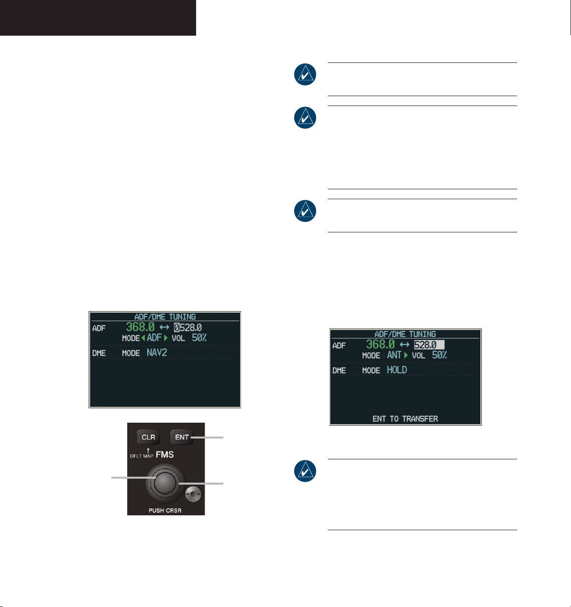
NAV/COM
Tuning and Transferring ADF Frequencies
ADF frequencies in the 190.0 kHz to 1799.5 kHz frequency range can be entered in the standby ADF frequency field of the ADF/DME Tuning window, using both the
dual FMS knob and the ENT key.
To enter an ADF frequency in the standby
field:
1. Turn the
large FMS
cursor over the standby ADF frequency field.
knob to place the selection
NOTE: The active ADF frequency field cannot be
edited directly.
NOTE: Pressing the CLR key while in data entry
mode (i.e., before having validated a standby
frequency being entered) causes the system to
cancel the current data entry for this field and
revert back to the previously entered standby
ADF frequency.
2. Turn the
entry and to change each digit, and turn the
large FMS
or previous character position.
3. Press the
standby frequency.
Turn the
small FMS
knob both to activate
data entry mode for
the standby ADF
frequency field and
to change each digit.
Figure 3-19 Entering ADF Standby Frequencies
small FMS
knob both to initiate data
knob to move the cursor to the next
ENT
key to validate data entry for the
Press the ENT
key to validate
the standby ADF
frequency entered.
Turn the large
FMS knob to move
the cursor to the
next or previous
character position.
NOTE: The G1000 system does not support tuning
of the 2182.0 kHz ADF emergency frequency.
To transfer the active and standby ADF frequencies:
1. Turn the
large FMS
knob to place the selection
cursor over the standby ADF frequency field.
ENT
2. Press the
Figure 3-20 Transferring ADF Frequencies
NOTE: Pressing the CLR key when the selection
cursor is flashing over the standby ADF frequency
field clears the existing standby frequency,
replaces it with ‘0000.0’ and puts the cursor in
data entry mode for this field.
key.
190-00592-00 Rev. AGarmin G1000 Pilot’s Guide for the Diamond DA403-10
Page 87
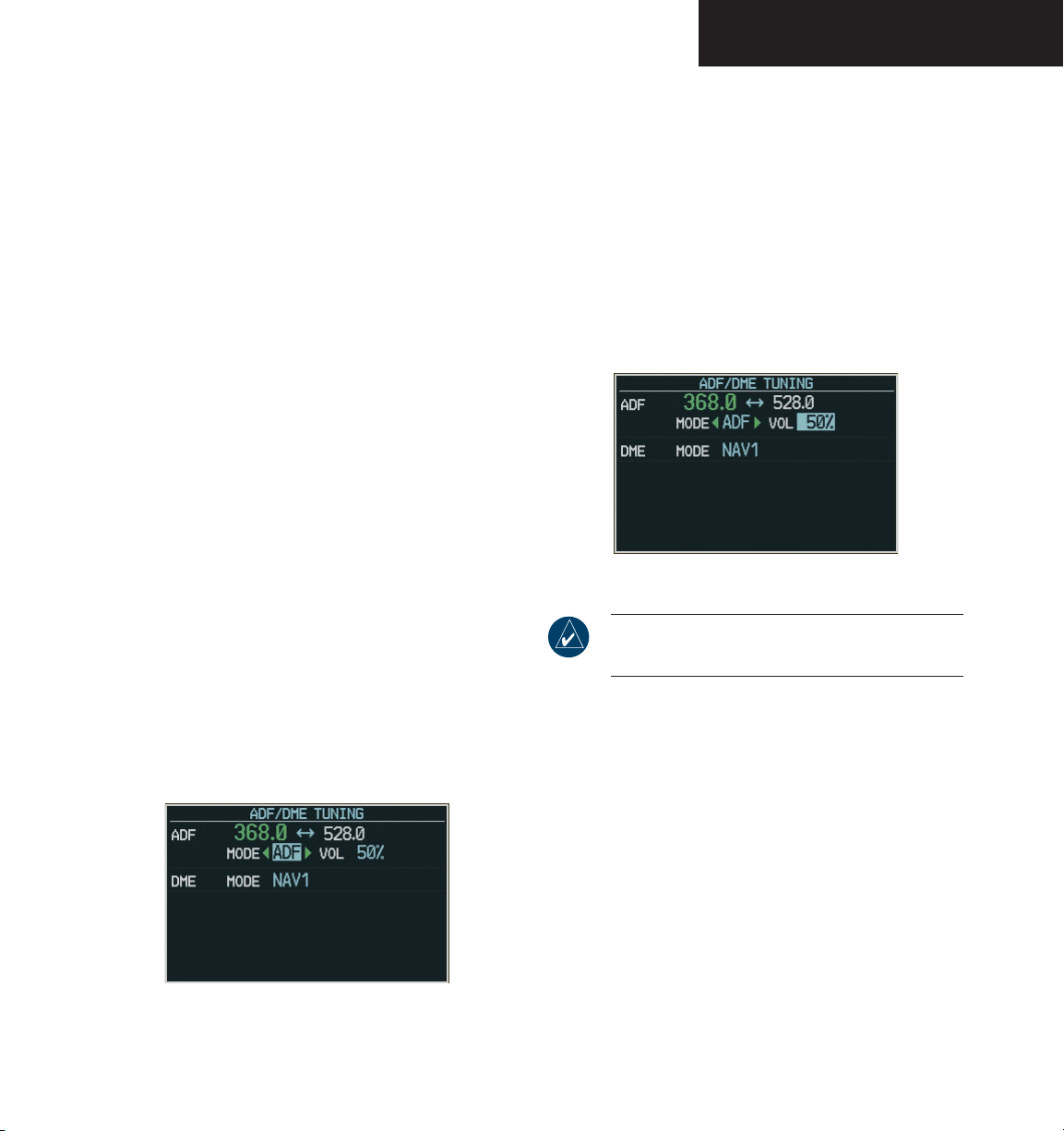
NAV/COM
Selecting the ADF Receiver Mode
The following modes can be selected:
• ANT (antenna) – The ADF bearing pointer is
deflected on the HSI by approximately 90 degrees
relative to the aircraft heading. In this mode, the
NDB Morse code identifier can only be heard if the
ADF key is selected on the audio panel.
• ADF – The ADF bearing pointer moves to point in
the direction of the NDB station. In this mode, the
NDB Morse code identifier can only be heard if the
ADF key is selected on the audio panel.
• BFO (Beat Frequency Oscillator) – Provides an
audible tone when a frequency is tuned. This mode
allows for the audio identification of the interrupted
carrier beacon stations that are used in various parts
of the world. In this mode, the NDB Morse code
identifier can only be heard if the ADF key is selected
on the audio panel.
To select an ADF receiver mode:
1. Turn the
large FMS
cursor over the ADF mode field.
knob to place the selection
Adjusting ADF Receiver Volume
ADF receiver volume level can be adjusted on the
ADF/DME Tuning window from 0 to 100% of available
volume in increments of one percentage point.
To adjust ADF receiver volume:
1. Turn the
large FMS
cursor over the ADF volume field.
2. Turn the
small FMS
desired.
Figure 3-22 Adjusting ADF Receiver Volume
NOTE: By default, ADF receiver volume level is
set to 50% of available volume.
knob to place the selection
knob to adjust volume as
2. Turn the
small FMS
knob to select the desired
ADF receiver mode.
Figure 3-21 Selecting ADF Receiver Mode
190-00592-00 Rev. A Garmin G1000 Pilot’s Guide for the Diamond DA40
3-11
Page 88
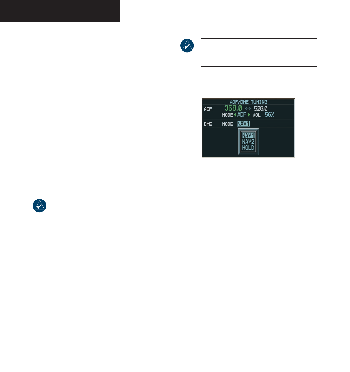
NAV/COM
Selecting the DME Transceiver Tuning Mode
The following DME transceiver tuning modes can be
selected:
• NAV1 – Tunes the DME frequency from the selected
NAV1 frequency.
• NAV2 – Tunes the DME frequency from the selected
NAV2 frequency.
• HOLD – When transitioning from NAV1 or NAV2
mode to HOLD mode, the DME frequency remains
set to the last selected NAV frequency.
To select a DME transceiver tuning mode:
NOTE: Please refer to the Primary Flight Display
section for information on the DME Information
window.
1. Turn the
large FMS
knob to place the selection
cursor over the DME tuning mode field.
2. Turn the
small FMS
knob to select the desired
DME tuning mode.
ENT
3. Press the
NOTE: Pressing the CLR key while in the process
of selecting DME tuning mode causes the system
to cancel data entry and revert back to the previously selected DME tuning mode.
key to validate the selection.
Figure 3-23 Selecting DME Tuning Mode
190-00592-00 Rev. AGarmin G1000 Pilot’s Guide for the Diamond DA403-12
Page 89
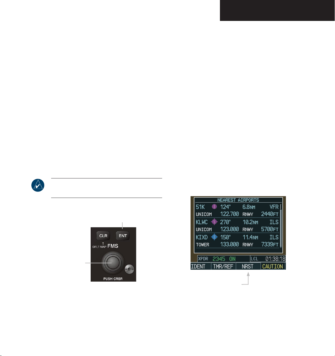
NAV/COM
3.5 FREQUENCY AUTO-TUNING
The G1000 system offers multiple auto-tuning
capabilities. The PFD allows auto-tuning of COM
frequencies associated with the nearest airports. The MFD
provides auto-tuning of both COM and NAV frequencies
from waypoint and nearest pages. In addition, the primary
NAV frequency is entered automatically in the NAV
window during approach loading or approach activation.
Frequencies can be automatically loaded into the
frequency windows in the following ways:
• By using the ENT key when the frequency is
highlighted on the appropriate page (PFD and
MFD).
• When loading or activating an approach (PFD and
MFD).
NOTE: Turn the FMS knob to scroll through a
list of frequencies.
AUTO-TUNING ON THE PFD
COM frequencies for the nearest airports may be
viewed and automatically loaded from the Nearest Airports
Window on the PFD.
To auto-tune a COM frequency for a nearby
airport:
NRST
1. Press the
Airports Window, which displays the list of
airport identifiers and COM frequencies.
2. Turn either
COM frequency.
3. Press the
into the COM tuning box.
When the desired frequency is entered in the tuning
box, it becomes a standby frequency. Pressing the
Frequency Transfer
active field.
softkey to open the Nearest
FMS
knob to highlight the desired
ENT
key to load the COM frequency
key places this frequency into the
Press the ENT key to load
a highlighted frequency into
the frequency window.
Turn the FMS knob
to scroll through a
list of frequencies.
Pressing the
Figure 3-24 Loading Frequencies
190-00592-00 Rev. A Garmin G1000 Pilot’s Guide for the Diamond DA40
the Nearest Airports window
NRST softkey opens
Figure 3-25 Nearest Airports Window (PFD)
3-13
Page 90
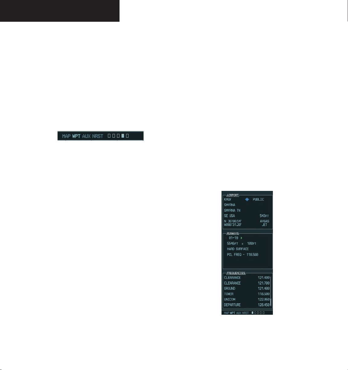
NAV/COM
AUTO-TUNING ON THE MFD
Frequencies can be selected and loaded from the
following MFD pages:
• WPT – Airport Information
• WPT – VOR Information
• NRST – Nearest Airports
• NRST – Nearest VOR
• NRST – Nearest (ARTCC, FSS, WX) Frequencies
Figure 3-26 MFD Page Group Icon
In NAV mode during any VOR/ILS approach activation,
the NAV frequency is automatically loaded into the
standby field of the selected NAV radio.
In GPS mode during any VOR/ILS approach activation,
the appropriate NAV frequency is automatically loaded
into the active field of NAV1.
WPT – Airport Information Window
The Airport Information Window displays runway
information and a list of frequencies for the selected airport
identifier as well as departure, arrival, and approach
information.
To display the entire list of frequencies for
an airport:
1. On the Airport Information Window, press the
INFO
softkey to display runway and frequency
information for a specific airport.
FMS
2. Press the
cursor in the window.
3. Turn the
identifier and press the
available frequencies for the selected airport
appears.
knob to activate the selection
FMS
knob to select the desired airport
ENT
key. A list of all
Figure 3-27 WPT – Airport Information Window
190-00592-00 Rev. AGarmin G1000 Pilot’s Guide for the Diamond DA403-14
Page 91
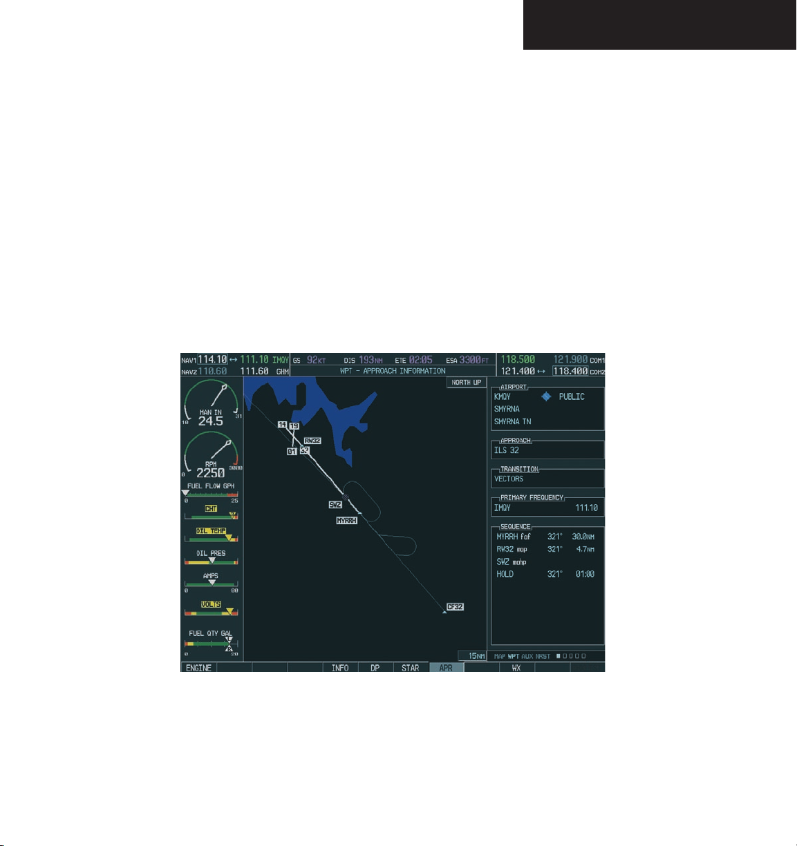
NAV/COM
To load a COM frequency into the COM
tuning box:
1. When the list of frequencies for the selected
airport is displayed, highlight the desired
frequency by turning the large
ENT
2. Press the
key.
FMS
knob.
The Pilot Controlled Lighting (PCL) frequency, located
in the Runways box of the INFO portion of the Airport
Information Page, may also be highlighted and loaded
into the COM tuning box.
To load the primary approach NAV
frequency into the NAV tuning box:
1 On the Airport Information Window, press the
APR
softkey to display approach information
for a specific airport.
FMS
2. Press the
knob to activate the selection
cursor in the window.
FMS
3. Turn the large
knob to highlight the
primary NAV frequency located in the Primary
Frequency box.
ENT
4. Press the
key.
Figure 3-28 WPT – Airport Information Page (APR)
190-00592-00 Rev. A Garmin G1000 Pilot’s Guide for the Diamond DA40
3-15
Page 92
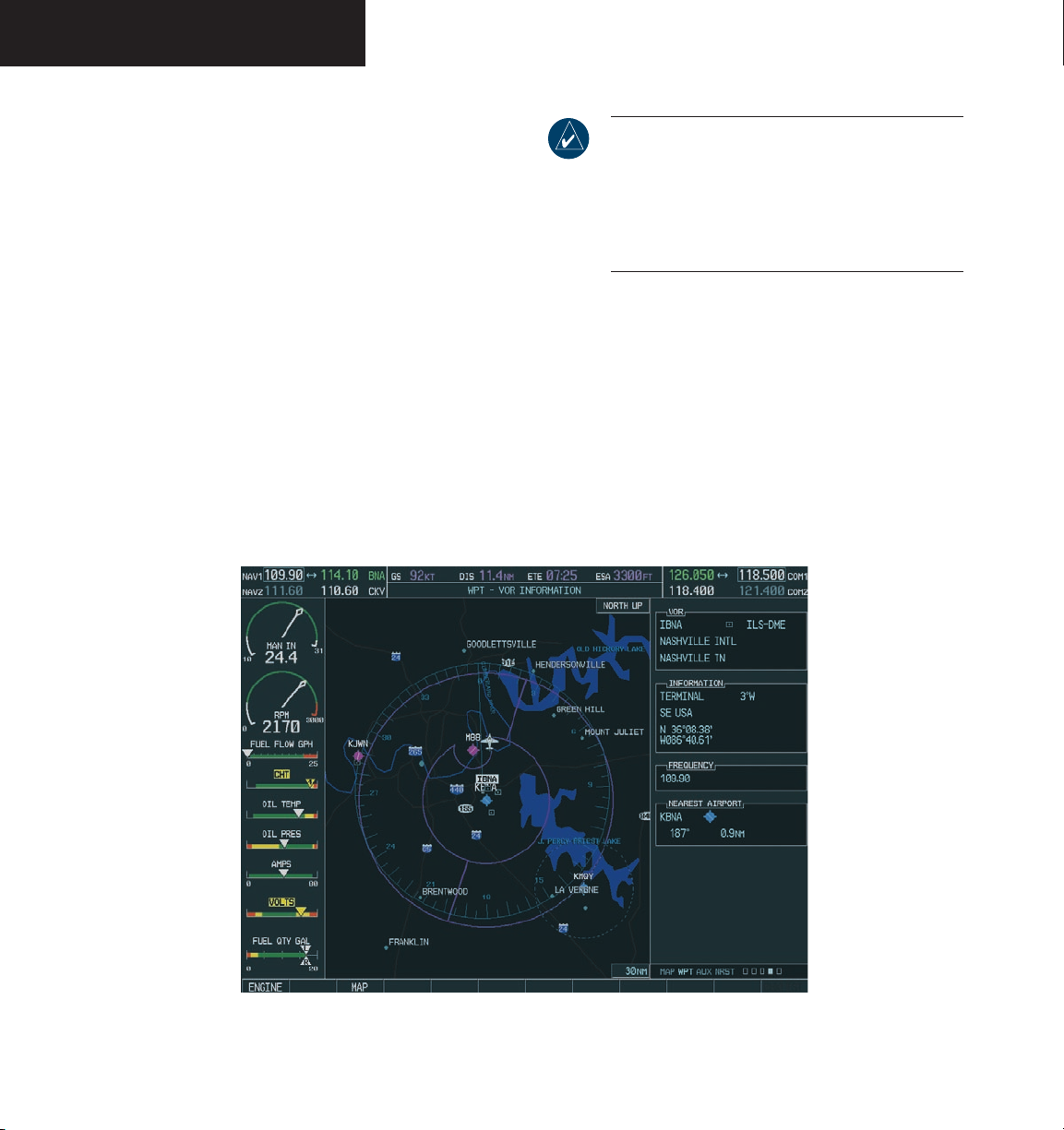
NAV/COM
WPT – VOR Information Page
The VOR Information Page displays information specific to individual VORs, including the airport that is nearest to the selected VOR.
To load a VOR frequency into the NAV
window:
1. On the VOR Information Page, press the
FMS
knob to activate the VOR Information
window.
FMS
2. Turn the
desired VOR and press the
the selection.
knob as needed to select the
ENT
key to validate
NOTE: If the MENU key is pressed when in the
VOR Information Page, the ‘View Recent VOR
List’ menu option is displayed for quick access to
recently used VORs. However, if no VOR frequencies have been tuned, this menu option is grayed
out.
3. Turn the
large FMS
frequency and press the
knob to highlight the VOR
ENT
key to load this
frequency into the tuning box of the NAV
Frequency window.
Figure 3-29 WPT – VOR Information Page
190-00592-00 Rev. AGarmin G1000 Pilot’s Guide for the Diamond DA403-16
Page 93
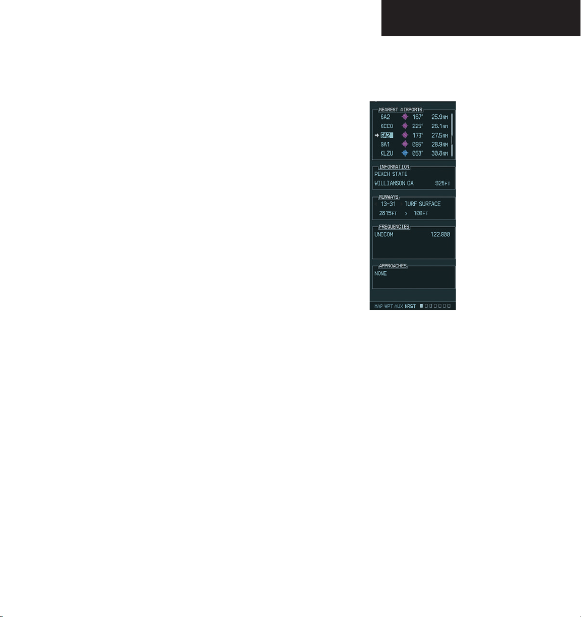
NRST – Nearest Airports Page
The Nearest Airports Page displays a list of the nearest
airports as well as related runway, frequency and approach
information. On this page, any frequency associated with
the selected airport can be loaded into the NAV or COM
Frequency window.
To display the entire list of frequencies for
a nearby airport and load a frequency from
that list:
1. On the Nearest Airports Page, press the
knob to activate the selection cursor in the
Nearest Airports window.
FMS
2. Turn the
knob to scroll through the list
of nearest airport identifiers until the desired
nearest airport is highlighted.
FREQ
3. Press the
softkey to activate the selection
cursor in the Frequencies box.
FMS
NAV/COM
FMS
4. Turn the
knob to scroll through the list of
Figure 3-30 NRST – Nearest Airport Page
frequencies for the selected airport.
5. When the desired frequency is highlighted,
ENT
press the
key to load this frequency into
the tuning box of the appropriate Frequency
window (NAV or COM).
190-00592-00 Rev. A Garmin G1000 Pilot’s Guide for the Diamond DA40
3-17
Page 94
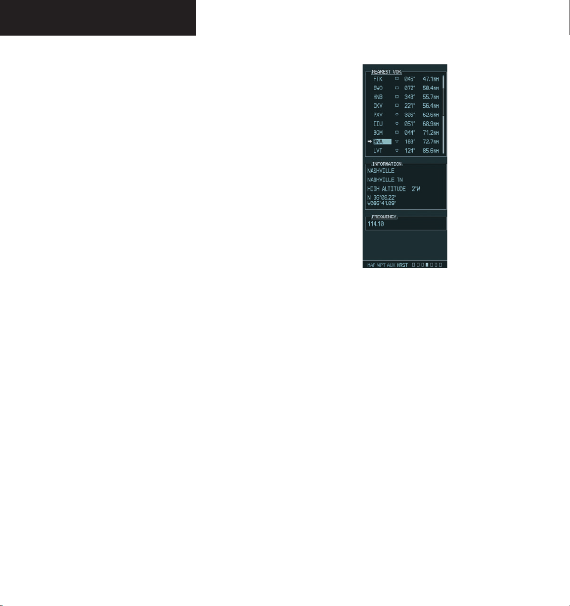
NAV/COM
NRST – Nearest VOR Page
The Nearest VOR Page displays a list of the nearest
VORs together with related information, including the associated VOR frequency.
To load a VOR frequency into the NAV
window:
FMS
1. On the Nearest VOR Page, press the
to activate the Nearest VOR window.
FMS
2. Turn the
knob to scroll through the list of
nearest VORs until the desired nearest VOR is
highlighted.
FREQ
3. Press the
softkey to activate the selection
cursor in the Frequency box and press the
key to load the frequency into the tuning box
of the NAV Frequency window.
knob
ENT
Figure 3-31 NRST – Nearest VOR Page
190-00592-00 Rev. AGarmin G1000 Pilot’s Guide for the Diamond DA403-18
Page 95
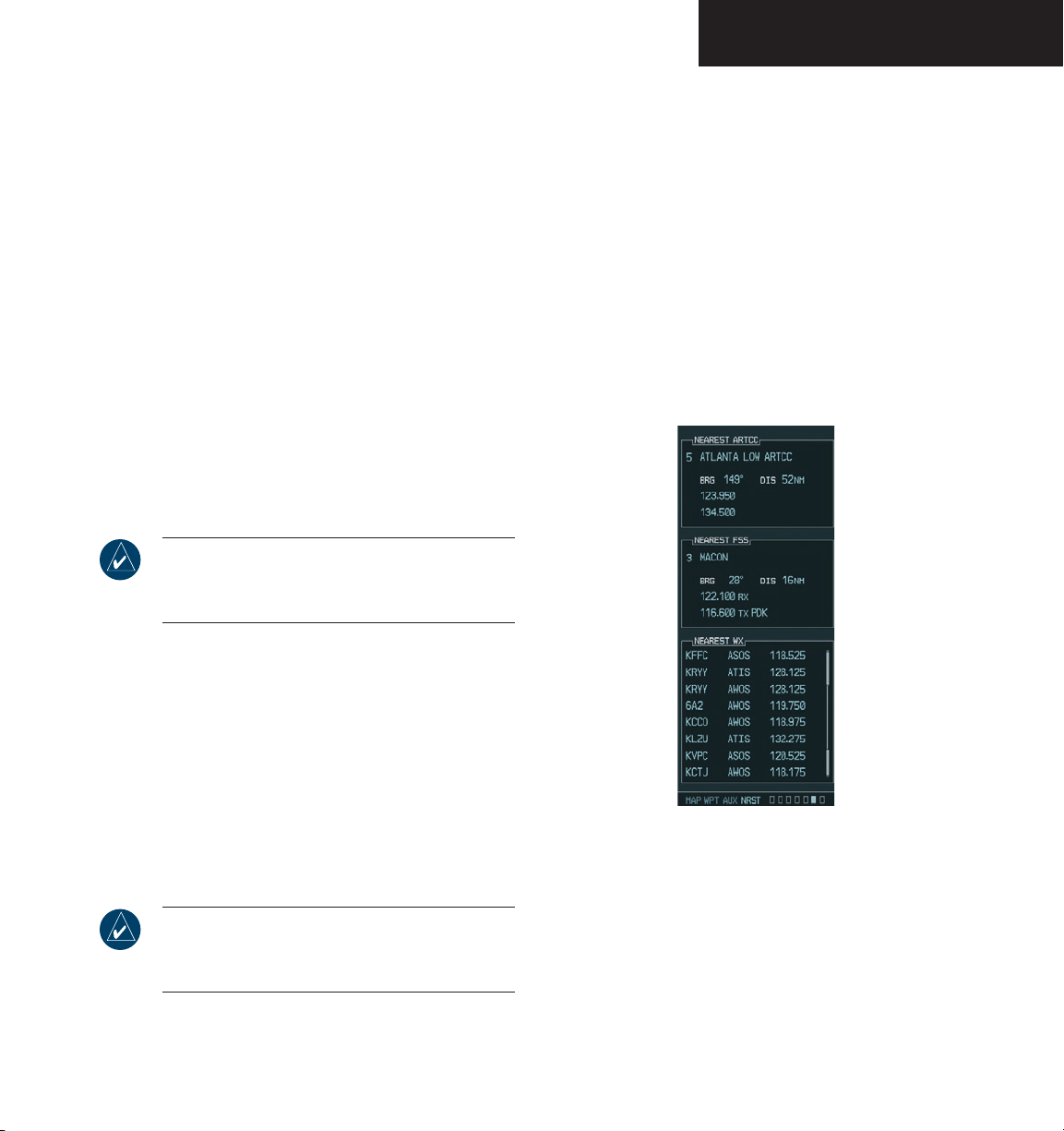
NAV/COM
NRST – Nearest Frequencies Page
The Nearest Frequencies Page displays a list of nearest
ARTCC, FSS and WX frequencies. For the purpose of frequency selection, the selection cursor can be activated on
the ARTCC, FSS, or WX box by using the ARTCC, FSS,
or WX softkeys, respectively.
To view a nearest ARTCC frequency and load
it into the standby frequency field:
ARTCC
1. Press the
tion cursor in the Nearest ARTCC box.
2. Turn the
small FMS
list of ARTCC names, then the
to highlight the desired ARTCC frequency.
3. Press the
frequency into the tuning box.
NOTE: The Nearest ARTCC box contains a numbered list of ARTCC names as well as associated
bearing and distance information.
softkey to activate the selec-
knob to scroll through the
large FMS
ENT
key to load the desired ARTCC
knob
To view a nearest WX frequency and load it
into the standby frequency field:
WX
1. Press the
softkey to activate the selection
cursor in the Nearest WX box.
FMS
2. Turn the
knob to highlight the desired WX
frequency.
ENT
3. Press the
key to load the desired WX fre-
quency into the tuning box.
To view a nearest FSS frequency and load it
into the standby frequency field:
FSS
1. Press the
softkey to activate the selection
cursor in the Nearest FSS box.
2. Turn the
small FMS
list of FSS names, then the
knob to scroll through the
large FMS
knob to
highlight the desired FSS frequency.
3. Press the
ENT
key to load the desired FSS
Figure 3-32 NRST – Nearest Frequencies Page
frequency into the tuning box.
NOTE: The Nearest FSS box contains a numbered
list of FSS names as well as associated bearing
and distance information.
190-00592-00 Rev. A Garmin G1000 Pilot’s Guide for the Diamond DA40
3-19
Page 96
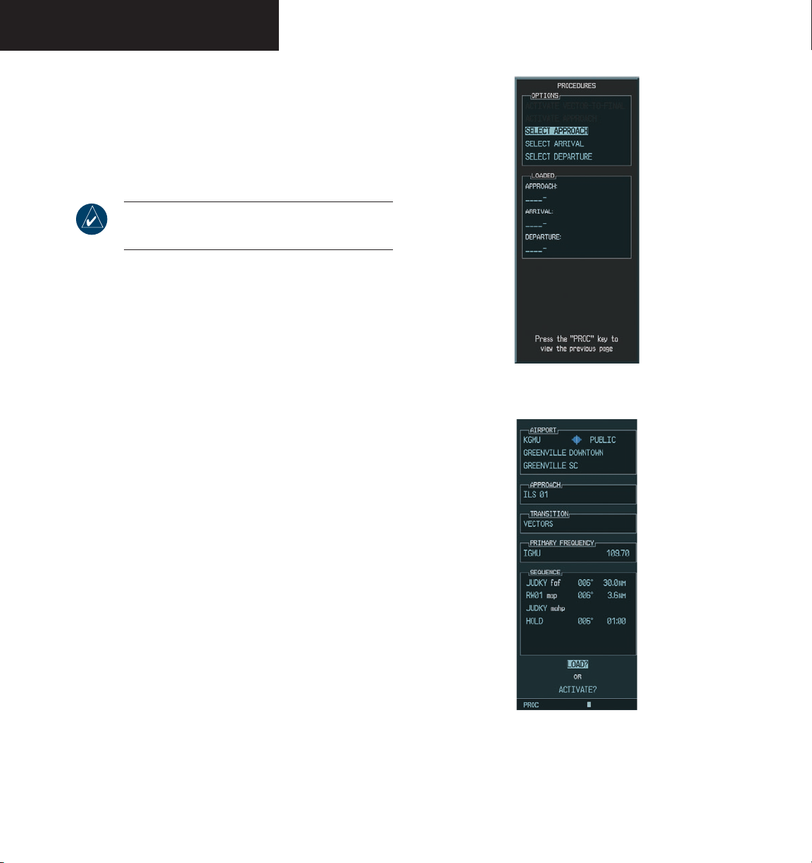
NAV/COM
AUTO-TUNING UPON APPROACH ACTIVATION (NAV FREQUENCIES)
NAV frequencies can be automatically loaded into the
NAV Frequency window upon approach activation, regardless of the display unit being used.
NOTE: The primary NAV frequency becomes
auto-tuned upon loading of an approach.
To auto-tune a NAV frequency if the desired
approach is not already loaded:
PROC
1. Press the
window.
key to open the Procedures
2. Turn the
large FMS
knob to highlight the
‘SELECT APPROACH’ menu option and press
the
ENT
key.
FMS
3. Use both the
knob and the
needed to select the desired airport, VOR/ILS
approach and transition.
4. Turn the
large FMS
knob to highlight either the
‘LOAD?’ or ‘ACTIVATE?’ prompt and press the
ENT
key. The primary NAV frequency for the
activated approach becomes loaded into the
standby field of the selected NAV radio.
ENT
Figure 3-33 Selecting an Approach
key as
Figure 3-34 Loading an Approach
190-00592-00 Rev. AGarmin G1000 Pilot’s Guide for the Diamond DA403-20
Page 97
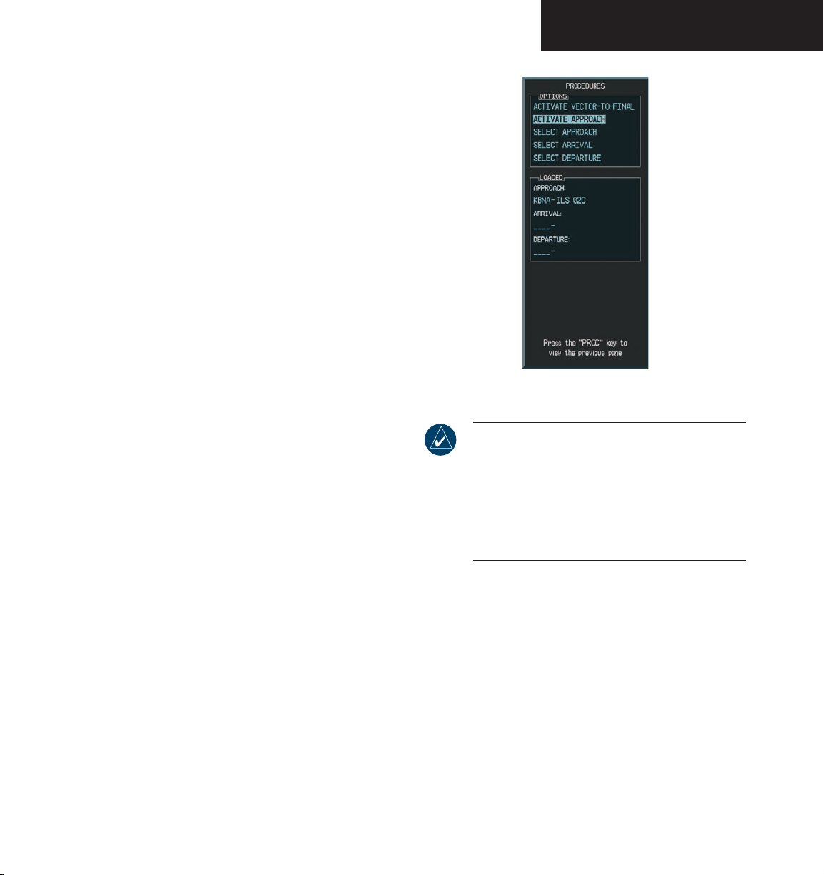
To auto-tune a NAV frequency if the desired
approach is already loaded:
PROC
1. Press the
key to open the Procedures
window.
NAV/COM
2. Turn the
large FMS
knob to highlight the
‘ACTIVATE APPROACH’ menu option and
press the
ENT
key. The approach primary NAV
frequency becomes automatically loaded into
the standby field of the selected NAV radio.
When loading or activating an approach, the primary
NAV frequency may be loaded into the NAV tuning box by
highlighting the frequency in the Select Approach window
using the
FMS
knob, then pressing the
ENT
key.
If the system is in GPS mode when a VOR/ILS
approach is loaded or activated, the approach primary
NAV frequency is automatically loaded into the active
field of NAV1.
The NAV frequency is also automatically loaded
upon vector-to-final activation. An approach can also
MENU
be activated with the
key when the Flight Plan
window is open.
Figure 3-35 Activating an Approach
NOTE: When a VOR/ILS approach has been acti-
vated in GPS mode, if the ILS CDI Capture option
on the AUX 4 Page is set to AUTO, the system
automatically switches to NAV mode as the final
approach course is intercepted (if within 15 nm
from the FAF). Please see the Multi Function
Display section for details on this feature.
190-00592-00 Rev. A Garmin G1000 Pilot’s Guide for the Diamond DA40
3-21
Page 98

NAV/COM
This page intentionally left blank
190-00592-00 Rev. AGarmin G1000 Pilot’s Guide for the Diamond DA403-22
Page 99

G1000
Transponder
TM
Page 100

Garmin G1000 Pilot’s Guide for the Diamond DA40 190-00592-00 Rev. A
 Loading...