


G950 |
™ |
Integrated Flight Deck |
|
Pilot’s Guide |
Tecnam P2006T


SYSTEM OVERVIEW
FLIGHT INSTRUMENTS
ENGINE INDICATION SYSTEM
AUDIO PANEL & CNS
FLIGHT MANAGEMENT
HAZARD AVOIDANCE
AUTOMATIC FLIGHT CONTROL SYSTEM
ADDITIONAL FEATURES
APPENDICES
INDEX

Copyright © 2010 Garmin Ltd. or its subsidiaries. All rights reserved.
This manual reflects the operation of System Software version 0935.01 or later. Some differences in operation may be observed when comparing the information in this manual to earlier or later software versions.
Garmin International, Inc., 1200 East 151st Street, Olathe, Kansas 66062, U.S.A.
Tel: 913/397.8200 |
Fax: 913/397.8282 |
Garmin AT, Inc., 2345 Turner Road SE, Salem, OR 97302, U.S.A. |
|
Tel: 503/391.3411 |
Fax: 503/364.2138 |
Garmin (Europe) Ltd., Liberty House, Bulls Copse Road, Hounsdown Business Park, Southampton, SO40 9RB, U.K |
|
Tel: 44/0870.8501241 |
Fax: 44/0870.8501251 |
Garmin Corporation, No. 68, Jangshu 2nd Road, Shijr, Taipei County, Taiwan |
|
Tel: 886/02.2642.9199 |
Fax: 886/02.2642.9099 |
For after-hours emergency, aircraft on ground (AOG) technical support for Garmin panel mount and integrated avionics systems, please contact Garmin’s AOG Hotline at 913.397.0836.
Website Address: www.garmin.com
Except as expressly provided herein, no part of this manual may be reproduced, copied, transmitted, disseminated, downloaded or stored in any storage medium, for any purpose without the express written permission of Garmin. Garmin hereby grants permission to download a single copy of this manual and of any revision to this manual onto a hard drive or other electronic storage medium to be viewed for personal use, provided that such electronic or printed copy of this manual or revision must contain the complete text of this copyright notice and provided further that any unauthorized commercial distribution of this manual or any revision hereto is strictly prohibited.
Garmin® is a registered trademark of Garmin Ltd. or its subsidiaries, and G950™ and SafeTaxi® are trademarks of Garmin Ltd. or its subsidiaries. These trademarks may not be used without the express permission of Garmin.
NavData® is a registered trademark of Jeppesen, Inc.; .S-TEC® is a registered trademark of S-TEC.
February 2010 |
Printed in the U.S.A |
Garmin G950 Pilot’s Guide for the Tecnam P2006T |
190-01146-00 Rev. A |

Limited Warranty
LIMITED WARRANTY
This Garmin product is warranted to be free from defects in materials or workmanship for two years from the date of purchase. Within this period, Garmin will, at its sole option, repair or replace any components that fail in normal use. Such repairs or replacement will be made at no charge to the customer for parts and labor, provided that the customer shall be responsible for any transportation cost. This warranty does not cover failures due to abuse, misuse, accident, or unauthorized alterations or repairs.
THE WARRANTIES AND REMEDIES CONTAINED HEREIN ARE EXCLUSIVE AND IN LIEU OF ALL OTHER WARRANTIES EXPRESS OR IMPLIED OR STATUTORY, INCLUDING ANY LIABILITY ARISING UNDER ANY WARRANTY OF MERCHANTABILITY OR FITNESS FOR A PARTICULAR PURPOSE, STATUTORY OR OTHERWISE. THIS WARRANTY GIVES YOU SPECIFIC LEGAL RIGHTS, WHICH MAY VARY FROM STATE TO STATE.
IN NO EVENT SHALL GARMIN BE LIABLE FOR ANY INCIDENTAL, SPECIAL, INDIRECT OR CONSEQUENTIAL DAMAGES, WHETHER RESULTING FROM THE USE, MISUSE, OR INABILITY TO USE THIS PRODUCT OR FROM DEFECTS IN THE PRODUCT. Some states do not allow the exclusion of incidental or consequential damages, so the above limitations may not apply to you.
Garmin retains the exclusive right to repair or replace the unit or software, or to offer a full refund of the purchase price, at its sole discretion. SUCH REMEDY SHALL BE YOUR SOLE AND EXCLUSIVE REMEDY FOR ANY BREACH OF WARRANTY.
Products sold through online auctions are not eligible for rebates or other secial offers from Garmin. Online auction confirmations are not accepted for warranty verification. To obtain warranty service, an original copy of the sales receipt from the original retailer is required. Garmin will not replace missing components from any package purchased through an online auction.
To obtain warranty service, contact your local Garmin Authorized Service Center. For assistance in locating a Service Center, visit the Garmin website at www.garmin.com or contact Garmin Customer Service at one of the numbers listed below:
Garmin International, Inc., 1200 East 151st Street, Olathe, Kansas 66062, U.S.A. |
|
|
Toll free: 800/800.1020 |
Tel: 913/397.8200 |
Fax: 913/397.8282 |
Garmin AT, Inc., 2345 Turner Road SE, Salem, OR 97302, U.S.A. |
|
|
Toll free: 800/525.6726 |
Tel: 503/391.3411 |
Fax: 503/364.2138 |
Garmin (Europe) Ltd., Liberty House, Bulls Copse Road, Hounsdown Business Park, Southampton, SO40 9RB, U.K |
||
Toll free (within U.K.): 0808 238 0000 |
Tel: 44/0870.8501241 |
Fax: 44/0870.8501251 |
Refer to the G950 Installation Manual for warranty registration instructions.
190-01146-00 Rev. A |
Garmin G950 Pilot’s Guide for the Tecnam P2006T |
i |

Warnings, Cautions, and Notes
WARNING: Navigation and terrain separation must NOT be predicated upon the use of the terrain avoidance feature. The terrain avoidance feature is NOT intended to be used as a primary reference for terrain avoidance and does not relieve the pilot from the responsibility of being aware of surroundings during flight. The terrain avoidance feature is only to be used as an aid for terrain avoidance. Terrain data is obtained from third party sources. Garmin is not able to independently verify the accuracy of the terrain data.
WARNING: The displayed minimum safe altitudes (MSAs) are only advisory in nature and should not be relied upon as the sole source of obstacle and terrain avoidance information. Always refer to current aeronautical charts for appropriate minimum clearance altitudes.
WARNING: The altitude calculated by G950 GPS receivers is geometric height above Mean Sea Level and could vary significantly from the altitude displayed by pressure altimeters, such as the GDC 74A Air Data Computer, or other altimeters in aircraft. GPS altitude should never be used for vertical navigation. Always use pressure altitude displayed by the G950 PFD or other pressure altimeters in aircraft.
WARNING: Do not use outdated database information. Databases used in the G950 system must be updated regularly in order to ensure that the information remains current. Pilots using any outdated database do so entirely at their own risk.
WARNING: Do not use basemap (land and water data) information for primary navigation. Basemap data is intended only to supplement other approved navigation data sources and should be considered as an aid to enhance situational awareness.
WARNING: Traffic information shown on the G950 Multi Function Display is provided as an aid in visually acquiring traffic. Pilots must maneuver the aircraft based only upon ATC guidance or positive visual acquisition of conflicting traffic.
WARNING: The Garmin G950 has a very high degree of functional integrity. However, the pilot must recognize that providing monitoring and/or self-test capability for all conceivable system failures is not practical. Although unlikely, it may be possible for erroneous operation to occur without a fault indication shown by the G950. It is thus the responsibility of the pilot to detect such an occurrence by means of crosschecking with all redundant or correlated information available in the cockpit.
 WARNING: For safety reasons, G950 operational procedures must be learned on the ground.
ii |
Garmin G950 Pilot’s Guide for the Tecnam P2006T |
190-01146-00 Rev. A |

Warnings, Cautions, and Notes
WARNING: The United States government operates the Global Positioning System and is solely responsible for its accuracy and maintenance. The GPS system is subject to changes which could affect the accuracy and performance of all GPS equipment. Portions of the Garmin G950 utilize GPS as a precision electronic NAVigation AID (NAVAID). Therefore, as with all NAVAIDs, information presented by the G950 can be misused or misinterpreted and, therefore, become unsafe.
WARNING: To reduce the risk of unsafe operation, carefully review and understand all aspects of the G950 Pilot’s Guide documentation and the Pilot’s Operating Handbook (POH) for the aircraft. Thoroughly practice basic operation prior to actual use. During flight operations, carefully compare indications from the G950 to all available navigation sources, including the information from other NAVAIDs, visual sightings, charts, etc. For safety purposes, always resolve any discrepancies before continuing navigation.
WARNING: The illustrations in this guide are only examples. Never use the G950 to attempt to penetrate a thunderstorm. Both the FAA Advisory Circular, Subject: Thunderstorms, and the Aeronautical Information Manual (AIM) recommend avoiding “by at least 20 miles any thunderstorm identified as severe or giving an intense radar echo.”
WARNING: Lamp(s) inside this product may contain mercury (HG) and must be recycled or disposed of according to local, state, or federal laws. For more information, refer to our website at www.garmin.com/ aboutGarmin/environment/disposal.jsp.
WARNING: Because of variation in the earth’s magnetic field, operating the G950 within the following areas could result in loss of reliable attitude and heading indications. North of 72° North latitude at all longitudes; South of 70° South latitude at all longitudes; North of 65° North latitude between longitude 75° W and 120° W. (Northern Canada); North of 70° North latitude between longitude 70° W and 128° W. (Northern Canada); North of 70° North latitude between longitude 85° E and 114° E. (Northern Russia); South of 55° South latitude between longitude 120° E and 165° E. (Region south of Australia and New Zealand)
WARNING: Do not use GPS to navigate to any active waypoint identified as a ‘NON WGS84 WPT’ by a system message. ‘NON WGS84 WPT’ waypoints are derived from an unknown map reference datum that may be incompatible with the map reference datum used by GPS (known as WGS84) and may be positioned in error as displayed.
190-01146-00 Rev. A |
Garmin G950 Pilot’s Guide for the Tecnam P2006T |
iii |

Warnings, Cautions, and Notes
CAUTION: The GDU 1040 PFD and GDU 1040 MFD displays use a lens coated with a special anti-reflective coating that is very sensitive to skin oils, waxes, and abrasive cleaners. CLEANERS CONTAINING AMMONIA WILL HARM THE ANTI-REFLECTIVE COATING. It is very important to clean the lens using a clean, lint-free cloth and an eyeglass lens cleaner that is specified as safe for anti-reflective coatings.
CAUTION: The Garmin G950 does not contain any user-serviceable parts. Repairs should only be made by an authorized Garmin service center. Unauthorized repairs or modifications could void both the warranty and the pilot’s authority to operate this device under FAA/FCC regulations.
nOTE: All visual depictions contained within this document, including screen images of the G950 panel and displays, are subject to change and may not reflect the most current G950 system. Depictions of equipment may differ slightly from the actual equipment.
NOTE:This device complies with part 15 of the FCC Rules. Operation is subject to the following two conditions:
(1) this device may not cause harmful interference, and (2) this device must accept any interference received, including interference that may cause undesired operation.
NOTE: Interference from GPS repeaters operating inside nearby hangars can cause an intermittent loss of attitude and heading displays while the aircraft is on the ground. Moving the aircraft more than 100 yards away from the source of the interference should alleviate the condition.
 NOTE: Use of polarized eyewear may cause the flight displays to appear dim or blank.
NOTE: This product, its packaging, and its components contain chemicals known to the State of California to cause cancer, birth defects, or reproductive harm. This notice is being provided in accordance with California’s Proposition 65. If you have any questions or would like additional information, please refer to our web site at www.garmin.com/prop65.
iv |
Garmin G950 Pilot’s Guide for the Tecnam P2006T |
190-01146-00 Rev. A |

Revision Information
|
|
|
Record of Revisions |
|
Part Number |
Revision |
Date |
Page Range |
Description |
190-01146-00 |
A |
2/10/10 |
i – I-6 |
Initial release for 9.15 software. |
|
|
|
|
|
190-01146-00 Rev. A |
Garmin G950 Pilot’s Guide for the Tecnam P2006T |
v |

Table of Contents
|
Section 1 System Overview |
|
1.1 |
Line Replaceable Units............................................ |
2 |
1.2 |
Secure Digital (SD) Cards........................................ |
6 |
1.3 |
System Power-up..................................................... |
7 |
1.4 |
System Operation.................................................... |
8 |
|
Display Operation.......................................................... |
8 |
|
G950 System Annunciations........................................... |
9 |
|
System Status............................................................. |
10 |
|
AHRS Operation.......................................................... |
12 |
|
GPS Receiver Operation............................................... |
13 |
1.5 |
G950 Controls........................................................ |
18 |
|
PFD/MFD Controls....................................................... |
18 |
|
Softkey Function......................................................... |
20 |
1.6 |
Accessing G950 Functionality.............................. |
25 |
|
Menus........................................................................ |
25 |
|
Data Entry.................................................................. |
25 |
|
Page Groups............................................................... |
27 |
|
System Settings........................................................... |
31 |
|
System Utilities........................................................... |
38 |
1.7 |
Display Backlighting.............................................. |
42 |
|
Section 2 Flight Instruments |
|
2.1 |
Flight Instruments.................................................. |
48 |
|
Airspeed Indicator....................................................... |
48 |
|
Attitude Indicator........................................................ |
50 |
|
Altimeter.................................................................... |
51 |
|
Vertical Speed Indicator (VSI)....................................... |
54 |
|
Vertical Deviation........................................................ |
54 |
|
Horizontal Situation Indicator (HSI)............................... |
55 |
|
Course Deviation Indicator (CDI)................................... |
60 |
2.2 |
Supplemental Flight Data..................................... |
67 |
|
Outside Air Temperature............................................... |
67 |
|
Wind Data.................................................................. |
68 |
|
Vertical Navigation (VNV) Indications............................ |
69 |
2.3 |
PFD Annunciations and Alerting Functions......... |
70 |
|
System Alerting........................................................... |
70 |
|
Marker Beacon Annunciations...................................... |
71 |
|
Traffic Annunciation..................................................... |
71 |
|
Altitude Alerting.......................................................... |
72 |
|
Low Altitude Annunciation........................................... |
72 |
|
Minimum Descent Altitude/Decision Height Alerting....... |
73 |
2.4 |
Abnormal Operations............................................ |
75 |
|
Abnormal GPS Conditions............................................ |
75 |
|
Unusual Attitudes........................................................ |
76 |
|
Section 3 Engine Indication System |
|
|
Section 4 Audio Panel and CNS |
|
4.1 |
Overview................................................................. |
79 |
|
PFD Controls and Frequency Display............................. |
80 |
|
GMA 1347 Audio Panel Controls................................... |
82 |
4.2 |
COM Operation...................................................... |
84 |
|
COM Transceiver Selection and Activation...................... |
84 |
|
COM Transceiver Manual Tuning................................... |
85 |
|
Quick-tuning and Activating 121.500 MHz..................... |
86 |
|
Auto-tuning the COM Frequency................................... |
87 |
|
Auto-tuning from the MFD........................................... |
88 |
|
Frequency Spacing....................................................... |
91 |
|
Automatic Squelch...................................................... |
92 |
|
Volume...................................................................... |
92 |
4.3 |
NAV Operation....................................................... |
93 |
|
NAV Radio Selection and Activation.............................. |
93 |
|
NAV Receiver Manual Tuning........................................ |
94 |
|
Auto-tuning a NAV Frequency from the MFD................. |
96 |
|
Auto-tuning NAV Frequencies on Approach Activation.. |
100 |
|
Marker Beacon Receiver............................................ |
101 |
4.4 GTX 33 Mode S Transponder.............................. |
102 |
|
|
Transponder Controls................................................. |
102 |
|
Transponder Mode Selection...................................... |
103 |
|
Entering a Transponder Code...................................... |
105 |
|
IDENT Function......................................................... |
106 |
|
Flight ID Reporting.................................................... |
107 |
4.5 |
Additional Audio Panel Functions...................... |
108 |
|
Power-Up................................................................. |
108 |
|
Mono/Stereo Headsets............................................... |
108 |
|
Speaker.................................................................... |
108 |
|
Intercom................................................................... |
109 |
|
Passenger Address (PA) System................................... |
111 |
|
Clearance Recorder and Player................................... |
111 |
|
Split COM Operation................................................. |
112 |
|
Entertainment Inputs................................................. |
113 |
4.6 Audio Panel Preflight Procedure........................ |
114 |
|
vi |
Garmin G950 Pilot’s Guide for the Tecnam P2006T |
190-01146-00 Rev. A |
Table of Contents
4.7 |
Abnormal Operation............................................ |
115 |
|
Stuck Microphone..................................................... |
115 |
|
COM Tuning Failure................................................... |
115 |
|
Audio Panel Fail-safe Operation.................................. |
115 |
|
PFD Failure (Reversionary Mode)............................... |
115 |
|
Section 5 Flight Management |
|
5.1 |
Introduction.......................................................... |
117 |
|
Navigation Status Box............................................... |
118 |
5.2 |
Using Map Displays............................................. |
120 |
|
Map Orientation....................................................... |
120 |
|
Map Range............................................................... |
122 |
|
Map Panning............................................................ |
124 |
|
Measuring Bearing and Distance................................ |
129 |
|
Topography.............................................................. |
130 |
|
Map Symbols............................................................ |
133 |
|
Airways.................................................................... |
139 |
|
Track Vector.............................................................. |
141 |
|
Wind Vector.............................................................. |
142 |
|
Nav Range Ring........................................................ |
143 |
|
Fuel Range Ring........................................................ |
144 |
|
Navigation Information Display.................................. |
145 |
5.3 |
Waypoints............................................................. |
151 |
|
Airports.................................................................... |
152 |
|
Intersections............................................................. |
158 |
|
NDBs....................................................................... |
160 |
|
VORs........................................................................ |
162 |
|
User Waypoints......................................................... |
164 |
5.4 |
Airspaces............................................................... |
170 |
5.5 Direct-to-Navigation .......................................... |
174 |
|
5.6 |
Flight Planning..................................................... |
181 |
|
Flight Plan Creation................................................... |
182 |
|
Adding Waypoints to an Existing Flight Plan................ |
187 |
|
Adding Airways to a Flight Plan.................................. |
189 |
|
Adding Procedures to a Stored Flight Plan................... |
192 |
|
Flight Plan Storage.................................................... |
199 |
|
Flight Plan Editing..................................................... |
201 |
|
Along Track Offsets.................................................... |
204 |
|
Parallel Track............................................................. |
206 |
|
Activating a Flight Plan Leg........................................ |
209 |
|
Inverting a Flight Plan................................................ |
210 |
|
Flight Plan Views....................................................... |
211 |
|
Closest Point of FPL................................................... |
213 |
5.7 |
Vertical Navigation.............................................. |
214 |
|
Altitude Constraints................................................... |
216 |
5.8 |
Procedures............................................................ |
220 |
|
Departures................................................................ |
220 |
|
Arrivals .................................................................... |
223 |
|
Approaches ............................................................. |
225 |
5.9 |
Trip Planning......................................................... |
231 |
|
Trip Planning............................................................. |
231 |
5.10 |
RAIM Prediction................................................... |
235 |
5.11 |
Navigating a Flight Plan..................................... |
239 |
5.12 |
Abnormal Operation............................................ |
267 |
|
Section 6 Hazard Avoidance |
|
6.1 |
Terrain Proximity.................................................. |
269 |
|
Displaying Terrain Proximity Data................................ |
270 |
|
Terrain Proximity Page............................................... |
272 |
6.2 |
Traffic Information Service (TIS)........................ |
274 |
|
Displaying TRAFFIC Data............................................ |
275 |
|
Traffic Map Page....................................................... |
278 |
|
TIS Alerts.................................................................. |
279 |
|
System Status........................................................... |
280 |
Section 7 Automatic Flight Control System |
||
7.1 |
S-TEC Fifty Five X Autopilot (Optional)............. |
283 |
|
Flight Director Mode Annunciation.............................. |
283 |
|
Altitude Preselect...................................................... |
283 |
|
Section 8 Additional Features |
|
8.1 |
SafeTaxi................................................................. |
285 |
|
SafeTaxi Database Cycle Number and Revision............. |
288 |
8.2 |
Scheduler.............................................................. |
291 |
|
Appendices |
|
Annunciations and Alerts.............................................. |
293 |
|
|
G950 System Message Advisories............................... |
299 |
|
Flight Plan Import/Export Messages............................ |
307 |
SD Card Use and Databases......................................... |
309 |
|
|
Jeppesen Databases.................................................. |
309 |
Glossary.......................................................................... |
313 |
|
Frequently Asked Questions......................................... |
321 |
|
General TIS Information................................................ |
325 |
|
Map Symbols.................................................................. |
327 |
|
|
Index |
|
190-01146-00 Rev. A |
Garmin G950 Pilot’s Guide for the Tecnam P2006T |
vii |

Table of Contents
Blank Page
viii |
Garmin G950 Pilot’s Guide for the Tecnam P2006T |
190-01146-00 Rev. A |

System Overview
Section 1 System Overview
The G950 Integrated Flight Deck System presents flight instrumentation, position, navigation, communication, and identification information to the pilot using flat-panel color displays. The system is distributed across the following Line Replaceable Units (LRUs):
• GDU 1040 Primary Flight Display (PFD) |
• GDC 74A Air Data Computer (ADC) |
• GDU 1040 Multi Function Display (MFD) |
• GTX 33 Mode S Transponder |
• GMA 1347 Audio Panel with Integrated Marker |
• GRS 77 Attitude and Heading Reference System |
Beacon Receiver |
(AHRS) |
• GIA 63W Integrated Avionics Units (IAU) |
• GMU 44 Magnetometer |
Figure 1-1 shows interactions between the LRUs. Additional/optional equipment are shown in Figure 1-2. The G950 is capable of interfacing with the following optional equipment:
•S-TEC 55X Autopilot
•KN 63 DME
•KR 87 ADF
INDEX APPENDICES ADDITIONALFEATURES AFCS AVOIDANCEHAZARD MANAGEMENTFLIGHT PANELCNSAUDIO& EIS INSTRUMENTSFLIGHT OVERVIEWSYSTEM
190-01146-00 Rev. A |
Garmin G950 Pilot’s Guide for the Tecnam P2006T |
1 |

ADDITIONAL HAZARD FLIGHT AUDIO PANEL FLIGHT SYSTEM INDEX APPENDICES FEATURES AFCS AVOIDANCE MANAGEMENT & CNS EIS INSTRUMENTS OVERVIEW
System Overview
1.1 Line Replaceable Units
•GDU 1040 (2) – The left-hand GDU is configured as a Primary Flight Display (PFD) and the right-hand GDU as a Multi Function Display (MFD). Both feature 10.4-inch LCD screens with 1024 x 768 resolution. The displays communicate with each other through a High-Speed Data Bus (HSDB) Ethernet connection. Each display is also paired with an Ethernet connection to an IAU.
•GMA 1347 (1) – The Audio Panel integrates navigation/communication radio (NAV/COM) digital audio, intercom, and marker beacon controls, and is installed between the displays. This unit also provides manual control of display reversionary mode (red DISPLAY BACKUP Button; see Section 1.5, System Operation) and communicates with both IAUs using an RS-232 digital interface.
•GIA 63W (2) – The Integrated Avionics Units (IAU) function as the main communication hubs, linking all LRUs with the on-side display. Each IAU contains a GPS WAAS receiver, VHF COM/NAV/GS receivers, and system integration microprocessors, and is paired with the on-side display via HSDB connection. The IAUs are not paired together and do not communicate with each other directly.
2 |
Garmin G950 Pilot’s Guide for the Tecnam P2006T |
190-01146-00 Rev. A |

System Overview
•GDC 74A (1) – The Air Data Computer (ADC) processes data from the pitot/static system and outside air temperature (OAT) sensor. The ADC provides pressure altitude, airspeed, vertical speed, and OAT information to the G950 System, and it communicates with the primary IAU, displays, and AHRS using an ARINC 429 digital interface.
EIS FLIGHT SYSTEM INSTRUMENTS OVERVIEW
•GTX 33 (1) – The solid-state Transponder provides Modes A, C, and S capability and communicates with both IAUs through an RS-232 digital interface.
•GRS 77 (1) – The Attitude and Heading Reference System (AHRS) provides aircraft attitude and heading information via ARINC 429 to both PFDs and the primary IAU. The AHRS contains advanced sensors (including accelerometers and rate sensors) and interfaces with the Magnetometer to obtain magnetic field information, with the ADC to obtain air data, and with both IAUs to obtain GPS information. AHRS operation is discussed in Section 1.4, System Operation.
•GMU 44 (1) – The Magnetometer measures local magnetic field and sends data to the AHRS for processing to determine aircraft magnetic heading. This unit receives power directly from the AHRS and communicates with it via an RS-485 digital interface.
ADDITIONAL AFCS HAZARD FLIGHT PANEL AUDIO FEATURES AVOIDANCE MANAGEMENT CNS &
INDEX APPENDICES
190-01146-00 Rev. A |
Garmin G950 Pilot’s Guide for the Tecnam P2006T |
3 |

ADDITIONAL HAZARD FLIGHT AUDIO PANEL FLIGHT SYSTEM INDEX APPENDICES FEATURES AFCS AVOIDANCE MANAGEMENT & CNS EIS INSTRUMENTS OVERVIEW
System Overview
GDU 1040 |
GMA 1347 |
GDU 1040 |
Primary Flight Display |
Audio Panel |
Multi-Function Display |
|
Reversionary |
Reversionary |
|
|
Control |
Control |
|
|
GDC 74A |
|
|
|
|
Air Data |
|
|
Computer |
|
|
No. 1 GIA 63W |
|
OAT |
No. 2 GIA 63W |
Integrated Avionics Unit |
|
Airspeed |
Integrated Avionics Unit |
|
Altitude |
||
|
|
|
|
|
Vertical Speed |
|
|
System Inegration Processors |
|
|
System Integration Processors |
I/O Processors |
|
|
I/O Processors |
VHF COM |
|
GRS 77 |
VHF COM |
VHF NAV/LOC |
|
VHF NAV/LOC |
|
GPS |
|
AHRS |
GPS |
Glideslope |
|
Glideslope |
|
|
|
||
|
|
Attitude |
|
GPS Output |
Rate of Turn |
GPS Output |
|
|
Slip/Skid |
||
|
|
|
|
GMU 44
Magnetometer
Heading
GTX 33
Transponder
Figure 1-1 Basic G950 Block Diagram
4 |
Garmin G950 Pilot’s Guide for the Tecnam P2006T |
190-01146-00 Rev. A |
System Overview
|
|
|
|
|
|
|
|
|
|
|
No. 2 GIA 63W |
||||
|
|
|
|||||
No. 1 GIA 63W |
|||||||
Integrated Avionics Unit |
Integrated Avionics Unit |
||||||
System Integration Processors |
System Integration Processors |
||||||
I/O Processors |
|
I/O Processors |
|||||
VHF COM |
|
VHF COM |
|||||
VHF NAV/LOC |
|
VHF NAV/LOC |
|||||
GPS |
|
|
GPS |
||||
Glideslope |
|
Glideslope |
|||||
|
|
|
|
|
|
|
|
|
|
|
|
|
|
|
|
KN 63 |
KR 87 |
DME |
ADF |
(optional) |
(optional) |
Figure 1-3 G950 With Optional/Additional Equipment
NOTE: For information on non-Garmin optional/additional equipment shown in Figure 1-3, consult the applicable optional interface user’s guide. This document assumes that the reader is already familiar with the operation of this additional equipment.
INDEX APPENDICES ADDITIONALFEATURES AFCS AVOIDANCEHAZARD MANAGEMENTFLIGHT PANELCNSAUDIO& EIS INSTRUMENTSFLIGHT OVERVIEWSYSTEM
190-01146-00 Rev. A |
Garmin G950 Pilot’s Guide for the Tecnam P2006T |
5 |

ADDITIONAL HAZARD FLIGHT AUDIO PANEL FLIGHT SYSTEM INDEX APPENDICES FEATURES AFCS AVOIDANCE MANAGEMENT & CNS EIS INSTRUMENTS OVERVIEW
System Overview
1.2 Secure Digital (SD) Cards
 NOTE: Ensure the G950 System is powered off before inserting an SD card.
 NOTE: Refer to Appendix B for instructions on updating the aviation database.
The PFD and MFD data card slots use Secure Digital (SD) cards and are located on the upper right side of the display bezels. Each display bezel is equipped with two SD card slots. SD cards are used for aviation database and system software updates as well as terrain database storage.
Installing an SD card:
1)Insert the SD card in the SD card slot (the front of the card should be flush with the face of the display bezel).
2)To eject the card, gently press on the SD card to release the spring latch.
SD Card Slots
Figure 1-3 Display Bezel SD Card Slots
6 |
Garmin G950 Pilot’s Guide for the Tecnam P2006T |
190-01146-00 Rev. A |

System Overview
1.3 System Power-up
 NOTE: Refer to Appendix A for system-specific annunciations and alerts.
The G950 System is integrated with the aircraft electrical system and receives power directly from electrical busses. The PFD, MFD, and supporting sub-systems include both power-on and continuous built-in test features that exercise the processor, RAM, ROM, external inputs, and outputs to provide safe operation.
During system initialization, test annunciations are displayed, as shown in Figure 1-4. All system annunciations should disappear typically within the first minute of power-up. Upon power-up, key annunciator lights also become momentarily illuminated on the Audio Panel, the MFD Control Unit, and the display bezels.
On the PFD, the AHRS begins to initialize and displays “AHRS ALIGN: Keep Wings Level”. The AHRS should display valid attitude and heading fields typically within the first minute of power-up. The AHRS can align itself both while taxiing and during level flight.
When the MFD powers up, the Power-up screen (Figure 1-5) displays the following information:
•System version
•Copyright
•Land database name and version
•SafeTaxi database information (see Additional Features)
•Terrain, Airport Terrain, Obstacle, and Aviation database name, version, and effective dates
Current database information includes valid operating dates, cycle number, and database type. When this information has been reviewed for currency (to ensure that no databases have expired), the pilot is prompted to continue.
Pressing the ENT Key (or right-most softkey) acknowledges this information, and the Navigation Map Page is displayed upon pressing the key a second time. When the system has acquired a sufficient number of satellites to determine a position, the aircraft’s current position is shown on the Navigation Map Page.
Figure 1-4 PFD Initialization |
Figure 1-5 Example MFD Power-up Screen |
INDEX APPENDICES ADDITIONALFEATURES AFCS AVOIDANCEHAZARD MANAGEMENTFLIGHT PANELCNSAUDIO& EIS INSTRUMENTSFLIGHT OVERVIEWSYSTEM
190-01146-00 Rev. A |
Garmin G950 Pilot’s Guide for the Tecnam P2006T |
7 |
HAZARD FLIGHT AUDIO PANEL FLIGHT SYSTEM AFCS AVOIDANCE MANAGEMENT & CNS EIS INSTRUMENTS OVERVIEW
System Overview
1.4 System Operation
NOTE: The G950 system alerts the pilot when backup paths are utilized by the LRUs. Refer to the Appendices for further information regarding system-specific alerts.
The displays are connected together via a single Ethernet bus for high-speed communication. As shown in Figure 1-1, each IAU is connected to the on-side display. This section discusses normal and reversionary G950 display operation, AHRS modes, GPS receiver operation, and G950 System Annunciations.
Display Operation
NOTE: In normal operating mode, backlighting can only be adjusted from the PFD (see Section 1.7). In reversionary mode, it can be adjusted from the remaining display(s).
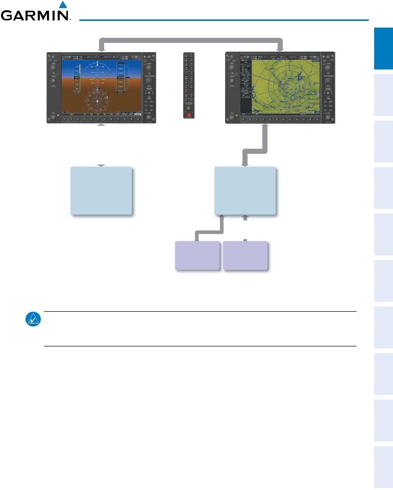
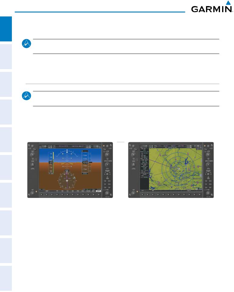
In normal operating mode, the PFD presents graphical flight instrumentation (attitude, heading, airspeed, altitude, vertical speed), replacing the traditional flight instrument cluster (see the Flight Instruments Section for more information). The MFD normally displays a full-color moving map with navigation information (see the Flight Management Section), while the left portion of the MFD is dedicated to the Engine Indication System (see the EIS Section). Both displays offer control for COM and NAV frequency selection.
Figure 1-6 G950 System Normal Operation
ADDITIONAL INDEX APPENDICES FEATURES
In the event of a display failure, the G950 System automatically switches to reversionary (backup) mode. In reversionary mode, all important flight information is presented on the remaining display(s) in the same format as in normal operating mode.
•PFD failure – MFD enters reversionary mode.
•MFD failure – PFD enters reversionary mode.
If a display fails, the appropriate IAU-display Ethernet interface is cut off. Thus, the IAU can no longer communicate with the remaining display (refer to Figure 1-1), and the NAV and COM functions provided to the failed display by the IAU are flagged as invalid on the remaining display. The system reverts to backup paths for the AHRS, ADC, Engine/Airframe Unit, and Transponder, as required. The change to backup paths is completely automated for all LRUs and no pilot action is required.
8 |
Garmin G950 Pilot’s Guide for the Tecnam P2006T |
190-01146-00 Rev. A |
System Overview
If the system fails to detect a display problem, reversionary mode may be manually activated by pressing the display backup button installed in the cockpit. Pressing this button again deactivates reversionary mode.
NAV1 and COM1 (provided by the failed PFD) Flagged Invalid
Figure 1-8 G950 Reversionary Mode (Failed PFD)
G950 System Annunciations
When an LRU or an LRU function fails, a large red ‘X’ is typically displayed over the instrument experiencing failed data (Figure 1-10 displays all possible flags and responsible LRUs). Upon G950 power-up, certain instruments remain invalid as equipment begins to initialize. All instruments should be operational within one minute of power-up. If any instrument remains flagged, the G950 should be serviced by a Garmin-authorized repair facility.
|
|
|
|
|
|
|
|
|||||||||||
GIA 63W Integrated |
|
|
|
|
GIA 63W Integrated |
|||||||||||||
|
Avionics Units |
|
|
|
|
|
|
|
|
|
|
|
|
|
Avionics Units |
|||
|
|
|
|
|
|
|
|
|
|
|
|
|
|
|
|
|
|
|
|
|
|
|
|
|
|
|
|
|
|
|
|
|
GDC 74A Air |
||||
|
|
|
|
|
|
|
|
|
|
|
|
|
|
|
Data Computer |
|
||
|
|
|
|
|
|
|
|
|
|
|
|
|
|
|
|
|
|
|
|
|
|
|
|
|
|
|
|
|
|
|
|
||||||
|
GDC 74A Air |
|
|
|
|
|
|
|
|
|
|
|
||||||
|
|
|
|
|
|
|
|
|
|
GRS 77 AHRS |
||||||||
|
|
|
|
|
|
|||||||||||||
|
Data Computer |
|
|
|
|
|
|
|
OR |
|
||||||||
|
|
|
|
|
|
|
|
|||||||||||
|
|
|
|
|
|
|
|
|
|
|
|
|
|
|
|
GMU 44 |
|
|
|
|
|
|
|
|
|
|
|
|
|
|
|
|
|
Magnetometer |
|
||
|
|
|
|
|
|
|
|
|
|
|
|
|
|
|
|
|
|
|
|
|
|
|
|
|
|
|
|
|
|
GIA 63W Integrated |
||
|
|
|
|
|
Avionics Units |
|
|
|
|
|
|
|
|
|
|
|
|
GTX 33 Transponder |
||
|
|
|
|
|
OR |
|
|
|
|
|
|||
|
|
|
|
|
GIA 63W Integrated |
|
Figure 1-10 G900X System Failure Annunciations |
|
Avionics Units |
||||
|
|
|||||
INDEX APPENDICES ADDITIONALFEATURES AFCS AVOIDANCEHAZARD MANAGEMENTFLIGHT PANELCNSAUDIO& EIS INSTRUMENTSFLIGHT OVERVIEWSYSTEM
190-01146-00 Rev. A |
Garmin G950 Pilot’s Guide for the Tecnam P2006T |
9 |

ADDITIONAL HAZARD FLIGHT AUDIO PANEL FLIGHT SYSTEM INDEX APPENDICES FEATURES AFCS AVOIDANCE MANAGEMENT & CNS EIS INSTRUMENTS OVERVIEW
System Overview
System Status
The System Status Page displays the statuses, serial numbers, and software version numbers for all detected system LRUs. Active LRUs are indicated by green check marks; failed, by red ‘X’s. Failed LRUs should be noted and a service center or Garmin-authorized dealer informed.
Viewing LRU information:
1)Use the FMS Knob to select the AUX - System Status Page.
2)To place the cursor in the ‘LRU Info’ Box,
a)Press the LRU Softkey.
Or:
a)Press the MENU Key.
b)With ‘Select LRU Window’ highlighted, press the ENT Key.
3)Use the FMS Knob to scroll through the box to view LRU status information.
Figure 1-11 Example System Status Page
10 |
Garmin G950 Pilot’s Guide for the Tecnam P2006T |
190-01146-00 Rev. A |

System Overview
Pertinent information on all system databases is also displayed on this page. Refer to the Appendices and Additional Features sections for more information about databases.
Viewing database information:
1)Use the FMS Knob to select the AUX - System Status Page.
2)To place the cursor in the ‘Database’ Box,
a)Press the DBASE Softkey.
Or:
a)Press the MENU Key.
b)Highlight ‘Select Dbase Window’ and press the ENT Key.
3)Use the FMS Knob to scroll through the box to view database status information.
The G950 uses aural tones to convey the priority of airframe-specific alerts. The alerting system’s annunciation tone may be tested from the System Status Page. Refer to the Appendices for airframe-specific alerts.
Testing the system annunciation tone:
1)Use the FMS Knob to select the AUX - System Status Page.
2)Press the ANN TEST Softkey.
Or:
a)Press the MENU Key.
b)Highlight ‘Enable Annunciator Test Mode’ and press the ENT Key.
INDEX APPENDICES ADDITIONALFEATURES AFCS AVOIDANCEHAZARD MANAGEMENTFLIGHT PANELCNSAUDIO& EIS INSTRUMENTSFLIGHT OVERVIEWSYSTEM
190-01146-00 Rev. A |
Garmin G950 Pilot’s Guide for the Tecnam P2006T |
11 |

FLIGHT SYSTEM INSTRUMENTS OVERVIEW
System Overview
AHRS Operation
 NOTE: Aggressive maneuvering while AHRS is not operating normally may degrade AHRS accuracy.
The Attitude and Heading Reference System (AHRS) performs attitude, heading, and vertical acceleration calculations for the G950 System, utilizing GPS, magnetometer, and air data in addition to information from its internal sensors. Attitude and heading information are updated on the PFD while the AHRS receives appropriate combinations of information from the external sensor inputs.
ADDITIONAL HAZARD FLIGHT AUDIO PANEL INDEX APPENDICES FEATURES AFCS AVOIDANCE MANAGEMENT & CNS EIS
GPS Data
|
availab |
|
|
unavailab |
|
Magnetometer Data |
|
|
|||
Magnetometer Data |
|||||
|
availab |
|
|
|
|
unavailab |
|
|||
|
|
|
|
Air Data |
||||||
|
|
|
|
availab |
|
|
|
unavailab |
|
|
|
|
|
AHRS noAHRS no-Mag/ |
|||||||
AHRS Normal |
||||||||||
Mag Mode |
|
no-Air Mode |
||||||||
Operation |
|
|||||||||
|
|
Heading Invalid |
||||||||
|
|
|
|
|
||||||
|
|
|
availab |
|
unavailab |
|
|
Air Data |
|
||||
|
|
|
||||
|
availab |
|
|
una |
|
|
|
|
|
v |
|
|
|
|
|
|
|
ailab |
|
|
|
|
|
|
le |
|
|
AHRS |
|
|
|
|||
no-GPS |
Attitude/Heading Invalid |
|||||
Mode |
||||||
Figure 1-12 AHRS Operation
Loss of GPS, magnetometer, or air data inputs is communicated to the pilot by message advisory alerts. Any failure of the internal AHRS inertial sensors results in loss of attitude and heading information (indicated by red ‘X’ flags over the corresponding flight instruments).
Two GPS inputs are provided to the AHRS. If GPS information from one of the inputs fails, the AHRS uses the remaining GPS input and an alert message is issued to inform the pilot. If both GPS inputs fail, the AHRS can continue to provide attitude and heading information to the PFD as long as magnetometer and airspeed data are available and valid.
If the magnetometer input fails, the AHRS continues to output valid attitude information; however, the heading output on the PFD is flagged as invalid with a red ‘X’.
Failure of the air data input has no effect on the AHRS output while AHRS is receiving valid GPS information. Invalid/unavailable airspeed data in addition to GPS failure results in loss of all attitude and heading information.
12 |
Garmin G950 Pilot’s Guide for the Tecnam P2006T |
190-01146-00 Rev. A |

System Overview
GPS Receiver Operation
Each Integrated Avionics Unit (IAU) contains a GPS receiver. Internal system checking is performed to ensure both GPS receivers are providing accurate data to the PFD. When both GPS receivers are providing accurate data, the GPS receiver producing the better solution is used by the system. Information collected by the specified receiver (GPS1 for the #1 IAU or GPS2 for the #2 IAU) may be viewed on the AUX - GPS Status Page.
Viewing GPS receiver status information:
1)Use the large FMS Knob on the MFD to select the Auxiliary Page Group (see Section 1.6 for information on navigating MFD page groups).
2)Use the small FMS Knob to select GPS Status Page (third page in the AUX Page Group).
3)To change the selected GPS receiver: Press the desired GPS Softkey.
Or:
a)Press the MENU Key.
b)Use the FMS Knob to highlight the receiver which is not selected and press the ENT Key.
|
|
|
Satellite Constellation |
Satellite Signal |
|
Diagram |
|
Information |
GPS
Receiver
Status
RAIM
Availability
Prediction
Satellite
Signal
Strength
Bars
Figure 1-13 GPS Status Page
INDEX APPENDICES ADDITIONALFEATURES AFCS AVOIDANCEHAZARD MANAGEMENTFLIGHT PANELCNSAUDIO& EIS INSTRUMENTSFLIGHT OVERVIEWSYSTEM
190-01146-00 Rev. A |
Garmin G950 Pilot’s Guide for the Tecnam P2006T |
13 |

ADDITIONAL HAZARD FLIGHT AUDIO PANEL FLIGHT SYSTEM APPENDICES FEATURES AFCS AVOIDANCE MANAGEMENT & CNS EIS INSTRUMENTS OVERVIEW
System Overview
GPS sensor annunciations are most often seen after system power-up when one GPS receiver has acquired satellites before the other or one of the GPS receivers has not yet acquired an SBAS signal. While the aircraft is on the ground, the SBAS signal may be blocked by obstructions causing one GPS receiver to have difficulty acquiring a good signal. Also, while airborne, turning the aircraft may result in one of the GPS receivers temporarily losing the SBAS signal. If no failure message exists, check the GPS Status Page and compare the information for GPS1 and GPS2. Discrepancies may indicate a problem.
GPS receiver status
The GPS solution type (ACQUIRING, 2D NAV, 2D DIFF NAV, 3D NAV, 3D DIFF NAV) for the active GPS receiver (GPS1 or GPS2) is shown in the upper right of the GPS Status Page. When the receiver is in the process of acquiring enough satellite signals for navigation, the receiver uses satellite orbital data (collected continuously from the satellites) and last known position to determine the satellites that should be in view. ACQUIRING is indicated as the solution until a sufficient number of satellites have been acquired for computing a solution.
When the receiver is in the process of acquiring a 3D differential GPS solution, 3D NAV is indicated as the solution until the 3D differential fix has finished acquisition. Satellite-Based Augmentation System (SBAS) status should be indicated as INACTIVE at this point. When acquisition is complete, the solution status changes to 3D DIFF NAV and SBAS becomes active.
• SBAS Selection (SBAS Softkey is pressed)
In certain situations, such as when the aircraft is outside or on the fringe of the SBAS coverage area, it may be desirable to disable WAAS or MSAS (although it is not recommended). When disabled, the SBAS field in the GPS Status box indicates DISABLED. There may be a small delay for the GPS Status box to be updated upon WAAS and MSAS enabling/disabling.
Disabling WAAS or MSAS
1)Select the GPS Status Page.
2)If necessary, press the SBAS Softkey.
3)Press the FMS Knob, and turn the large FMS Knob to hightlight ‘MSAS’ or ‘WAAS’.
4)Press the ENT Key to uncheck the box.
5)Press the FMS Knob to remove the cursor
Figure 1-14 Enable/Disable SBAS
INDEX
14 |
Garmin G950 Pilot’s Guide for the Tecnam P2006T |
190-01146-00 Rev. A |

System Overview
RAIM Prediction
Receiver Autonomous Integrity Monitoring (RAIM) is a GPS receiver function that performs a consistency check on all tracked satellites. RAIM ensures that the available satellite geometry allows the receiver to calculate a position within a specified RAIM protection limit (2.0 nautical miles for oceanic and enroute, 1.0 nm for terminal, and 0.3 nm for non-precision approaches). During oceanic, enroute, and terminal phases of flight, RAIM is available nearly 100% of the time.
The RAIM prediction function also indicates whether RAIM is available at a specified date and time. RAIM computations predict satellite coverage within ±15 min of the specified arrival date and time. In most cases performing RAIM prediction is not necessary. However, in some cases, the selected approach may be outside the WAAS coverage area and it may be necessary to perform a RAIM prediction for the intended approach.
Because of the tighter protection limit on approaches, there may be times when RAIM is not available. The G950 automatically monitors RAIM and warns with an alert message when it is not available. If RAIM is not predicted to be available for the final approach course, the approach does not become active, as indicated by the messages “Approach is not active”. If RAIM is not available when crossing the FAF, the missed approach procedure must be flown.
Predicting RAIM availability:
1)Select the GPS Status Page.
2)Press the RAIM Softkey.
3)Press the FMS Knob. The ‘WAYPOINT’ field is highlighted.
4)Turn the small FMS Knob to display the Waypoint Information Window.
5)Enter the desired waypoint:
a)Use the FMS Knob to enter the desired waypoint by identifier, facility, or city name and press the ENT Key. Refer to Section 1.7 for instructions on entering alphanumeric data into the G950.
Or:
a)Turn the small FMS Knob counter-clockwise to display a list of flight plan waypoints (the FPL list is populated only when navigating a flight plan).
b)Turn the small FMS Knob clockwise to display the NRST, RECENT, or AIRWAY waypoints, if required.
c)Turn the large FMS Knob clockwise to select the desired waypoint. The G950 automatically fills in the identifier, facility, and city fields with the information for the selected waypoint.
d)Press the ENT Key to accept the waypoint entry.
6)Enter an arrival time and press the ENT Key.
7)Enter an arrival date and press the ENT Key.
8)With the cursor highlighting ‘COMPUTE RAIM?’, press the ENT Key. Once RAIM availability is computed, one of the following is displayed:
•‘COMPUTE RAIM?’—RAIM has not been computed for the current waypoint, time, and date combination
•‘COMPUTING AVAILABILITY’—RAIM calculation in progress
•‘RAIM AVAILABLE’—RAIM is predicted to be available for the specified waypoint, time, and date
•‘RAIM NOT AVAILABLE’—RAIM is predicted to be unavailable for the specified waypoint, time, and date
INDEX APPENDICES ADDITIONALFEATURES AFCS AVOIDANCEHAZARD MANAGEMENTFLIGHT PANELCNSAUDIO& EIS INSTRUMENTSFLIGHT OVERVIEWSYSTEM
190-01146-00 Rev. A |
Garmin G950 Pilot’s Guide for the Tecnam P2006T |
15 |

ADDITIONAL HAZARD FLIGHT AUDIO PANEL FLIGHT SYSTEM INDEX APPENDICES FEATURES AFCS AVOIDANCE MANAGEMENT & CNS EIS INSTRUMENTS OVERVIEW
System Overview
Predicting RAIM availability at present position
1)Select the GPS Status Page.
2)If necessary, press the RAIM Softkey.
3)Press the FMS Knob. The ‘WAYPOINT’ field is highlighted.
4)Press the MENU Key.
5)With ‘Set WPT to Present Position’ highlighted, press the ENT Key.
6)Press the ENT Key to accept the waypoint entry.
7)Use the FMS Knob to enter an arrival time and press the ENT Key.
8)Use the FMS Knob to enter an arrival date and press the ENT Key.
9)With the cursor highlighting ‘COMPUTE RAIM?’, press the ENT Key. Once RAIM availability is computed, one of the following is displayed:
•‘COMPUTE RAIM?’—RAIM has not been computed for the current waypoint, time, and date combination
•‘COMPUTING AVAILABILITY’—RAIM calculation in progress
•‘RAIM AVAILABLE’—RAIM is predicted to be available for the specified waypoint, time, and date
•‘RAIM NOT AVAILABLE’—RAIM is predicted to be unavailable for the specified waypoint, time, and date
Satellite Information
Satellites currently in view are shown at their respective positions on a satellite constellation diagram. This sky view is always oriented north-up, with the outer circle representing the horizon, the inner circle representing 45° above the horizon, and the center point showing the position directly overhead. Each satellite is represented by an oval containing the Pseudo-random noise (PRN) number (i.e., satellite identification number). Satellites whose signals are currently being used are represented by solid ovals.
The GPS Status Page can be helpful in troubleshooting weak (or missing) signal levels due to poor satellite coverage or installation problems. As the GPS receiver locks onto satellites, a signal strength bar is displayed for each satellite in view, with the appropriate satellite PRN number (01-32 or 120-138 for WAAS) below each bar. The progress of satellite acquisition is shown in three stages, as indicated by signal bar appearance:
-No bar—Receiver is looking for the indicated satellite
-Hollow bar—Receiver has found the satellite and is collecting data
-Light blue bar—Receiver has collected the necessary data and the satellite signal can be used
-Green bar—Satellite is being used for the GPS solution
-Checkered bar—Receiver has excluded the satellite (Fault Detection and Exclusion)
-“D” indication—Denotes the satellite is being used as part of the differential computations
Each satellite has a 30-second data transmission that must be collected (signal strength bar is hollow) before the satellite may be used for navigation (signal strength bar becomes solid).
Using the current satellite signal information, they system calculates the aircraft’s GPS position, time, altitude, ground speed, and track for the aircraft (displayed below the satellite signal accuracy measurements for reference). The following quantities denote the accuracy of the aircraft’s GPS fix:
16 |
Garmin G950 Pilot’s Guide for the Tecnam P2006T |
190-01146-00 Rev. A |

System Overview
•Estimated Position Uncertainty (EPU)—A statistical error indication; the radius of a circle centered on an estimated horizontal position in which actual position has 95% probability of lying
•Horizontal Dilution of Precision (HDOP)—Measures satellite geometry quality (i.e., number of satellites received and where they are relative to each other) on a range from 0.0 to 9.9, with lower numbers denoting better accuracy
•Horizontal and Vertical Figures of Merit (HFOM and VFOM)—Measures of horizontal and vertical position uncertainty; the current 95% confidence horizontal and vertical accuracy values reported by the GPS receiver
INDEX APPENDICES ADDITIONALFEATURES AFCS AVOIDANCEHAZARD MANAGEMENTFLIGHT PANELCNSAUDIO& EIS INSTRUMENTSFLIGHT OVERVIEWSYSTEM
190-01146-00 Rev. A |
Garmin G950 Pilot’s Guide for the Tecnam P2006T |
17 |

ADDITIONAL HAZARD FLIGHT AUDIO PANEL FLIGHT SYSTEM INDEX APPENDICES FEATURES AFCS AVOIDANCE MANAGEMENT & CNS EIS INSTRUMENTS OVERVIEW
System Overview
1.5 G950 Controls
The G950 controls have been designed to simplify operation of the system and minimize workload and the time required to access sophisticated functionality. Controls are located on the PFD and MFD bezels, and the Audio Panel. PFD and MFD controls and softkeys are discussed in this section. Audio Panel controls are described in the Audio Panel and CNS section; see the Audio Panel and CNS Section for more information about NAV/COM controls.
PFD/MFD Controls
1 |
2 |
3 |
4 |
5 |
6 |
7 |
8 |
9 |
10 |
13 |
11 |
14 |
12 |
15 |
16 |
|
18 |
17 |
Figure 1-15 PFD/MFD Controls
1 NAV VOL/ID Knob Turn to control NAV audio volume (shown in the NAV Frequency Box as a percentage)
Press to toggle Morse code identifier audio ON/OFF
2NAV Frequency Transfers the standby and active NAV frequencies
Transfer Key
3 |
NAV Knob |
Turn to tune NAV receiver standby frequencies (large knob for MHz; small for kHz) |
|
|
Press to toggle light blue tuning box between NAV1 and NAV2 |
4 |
Heading Knob |
Turn to manually select a heading |
Press to display a digital heading momentarily to the left of the HSI and synchronize the Selected Heading to the and current heading
18 |
Garmin G950 Pilot’s Guide for the Tecnam P2006T |
190-01146-00 Rev. A |
 Loading...