


 Loading...
GHP™ 10 Marine Autopilot System Installation Instructions
To obtain the best possible performance and to avoid damage to your boat, install your GHP 10 marine autopilot system according to the following instructions. Read all installation instructions before proceeding with the installation. If you experience difficulty during the installation, contact Garmin Product Support, or seek the advice of a professional installer.
Product Registration
Help us better support you by completing our online registration today! Connect to our Web site at http://my.garmin.com. Keep the original sales receipt, or a photocopy, in a safe place.
For future reference, write the serial number assigned to each component of your GHP 10 system in the spaces provided on page 2. The serial numbers are located on a sticker on each component.
Contact Garmin
Contact Garmin if you have any questions while using your GHP 10. In the USA contact Garmin Product Support by phone: (913) 397-8200 or (800) 800-1020, or go to www.garmin.com/support/.
In Europe, contact Garmin (Europe) Ltd. at +44 (0) 870.8501241 (outside the UK) or 0808 2380000 (within the UK).
 Warnings
•You are responsible for the safe and prudent operation of your vessel. The GHP 10 is a tool that will enhance your capability to operate your boat. It does not relieve you from the responsibility of safely operating your boat. Avoid navigational hazards and never leave the helm unattended.
•Always be prepared to promptly regain manual control of your boat.
•Learn to operate the GHP 10 on calm and hazard-free open water.
•Use caution when operating the GHP 10 at high speeds near hazards in the water, such as docks, pilings, and other boats.
•See the Important Safety and Product Information guide in the product box for product warnings and other important information.
 Cautions
•Always wear safety goggles, ear protection, and a dust mask when drilling, cutting, or sanding.
•When drilling or cutting, always check the opposite side of the surface. Be aware of fuel tanks, electrical cables, and hydraulic hoses.
June 2008 |
190-00894-02 Rev. A |
Printed in Taiwan |

GHP 10 Package Contents and Tools Needed
The GHP 10 autopilot system consists of multiple components. Familiarize yourself with all of the components before beginning installation. You must know how the components operate together in order to correctly plan the installation on your boat.
As you familiarize yourself with the GHP10 components, confirm that your package includes the following items.All the components except for the hydraulic pump are included in the GHP 10 core box. The pump is packaged separately. If any parts are missing, contact your Garmin dealer immediately.
The Main Components
The GHP10 autopilot system consists of five main components: the Electronic Control Unit (ECU), the Course Computer Unit
(CCU), a hydraulic pump, the Shadow Drive™, and the GHC™ 10 user control interface.
The Course Computer Unit (CCU)
The CCU acts as the “brain” of the GHP 10. The CCU contains the sensory equipment used to determine
heading and engine speed. The CCU connects to the Electronic Control Unit (ECU), to the GHC 10, and
to the tachometer of your boat with a single cable. The CCU also connects to a NMEA 2000® network to
communicate with the GHC 10, and to an optional NMEA 2000-compatible GPS device.
Garmin part number: 010-11052-00
Serial number
The Electronic Control Unit (ECU)
The ECU connects to the CCU and to the pump. The ECU controls the pump based on information from the CCU. The ECU powers both the CCU and the pump.
Garmin part number: 010-11053-00


 Serial number
The Hydraulic Pump (and motor)
The hydraulic pump (and motor) steers your boat by interacting with the hydraulic steering system, based on commands you enter using the GHC 10. The pump is not included in the GHP 10 core package box because the type of pump you use with your GHP 10 is determined by the engine and steering system of your boat. The pump is in a separate box.
|
|
Garmin part numbers: 010-11097-00 (2.0 L pump), 010-11098-00 |
1.2 L/2.0 L Pump |
2.1 L Pump |
(1.2 L pump), and 010-11099-00 (2.1 L pump) |
Serial number
The Shadow Drive
The Shadow Drive is a sensor you install in the hydraulic steering lines of your boat. While the GHP 10 is engaged, the Shadow Drive temporarily disengages the autopilot when you manually take control of the
helm. When you manually steer the boat in a straight line again, the Shadow Drive allows the autopilot to
resume control.
Garmin part number: 010-11054-00
Serial number
|
GHP 10 Marine Autopilot System Installation Instructions |

The GHC 10
Use the GHC 10 to operate the GHP 10 autopilot system. Using the GHC 10, you engage and steer the GHP 10. You also set up and customize the GHP 10 using the GHC 10. The GHC 10 connects to a NMEA 2000 network to communicate with the CCU and with an optional NMEA 2000-compatible GPS device (to use waypoint and route information). If a NMEA 2000-compatible GPS device is not
available, you can wire the GHC 10 to an optional NMEA 0183-compatible GPS device instead. Garmin part number: 010-00688-00
Serial number
Cables and Connectors
The GHP 10 autopilot system contains multiple cables. These cables connect the components to power, to each other, to an alarm, and to optional devices such as a NMEA 0183-compatible GPS device.
CCU/ECU Interconnect Cable
This cable connects the CCU to the ECU. A portion of this cable contains color-coded wires with bare ends. These wires connect the CCU to the tachometer of your boat, to the Shadow Drive, and to the alarm. (Garmin part number: 010-11055-00)
The Alarm
The alarm is wired to the CCU and provides audible alerts from the GHP 10. See page 18. (Garmin part number: 010-11056-00)
ECU Power Cable
This cable powers the ECU. Wire this to the battery of your boat as one of the last connections made in the GHP 10 installation. See page 24. (Garmin part number: 010-11057-00)
GHC 10 Power/Data Cable
This cable is included in the GHC 10 box. Wire this cable to the battery of your boat as one of the last connections made in the GHP 10 installation. This cable is used to wire to an optional NMEA 0183-compatible GPS device. See page 20.
(Garmin part number: 320-00023-07)
GHP 10 Marine Autopilot System Installation Instructions |
|

NMEA 2000 Cables and Connectors
The NMEA 2000 cables connect the CCU and the GHC 10 to the NMEA 2000 network. Use the NMEA 2000 power cable and two terminators to create a NMEA 2000 network on your boat if one does not exist. For more information on NMEA 2000, see page 21.
NMEA 2000 drop cable, 6 ft. (2 m) (×2), Garmin part number: 320-00387-00 |
NMEA 2000 T-connector (×3), Garmin part |
|
|
number: 330-00563-00 |
|
NMEA 2000 power cable, Garmin part number: 320-00389-00 (×1) |
NMEA 2000 terminators, male Garmin part |
|
|
number: 330-00564-00 |
(×1); female Garmin part |
|
number: 330-00565-00 |
(×1) |
CCU/ECU Interconnect Extension Cables (Not Included)
When installing the GHP 10 system, you may need to mount the CCU farther than 91/2 ft. (3 m) from the ECU. Garmin offers two optional extension cables for purchase if this is necessary, a 161/2 ft. (5 m) cable (Garmin part number 010-11156-00) and a 49 ft. (15 m) cable (Garmin part number: 010-11156-01). Contact your local Garmin dealer or Garmin Product Support for ordering information.
Tools Needed
•Safety glasses
•Drill and drill bits
•Jigsaw or 317/32 in. (90 mm) hole saw
•Center punch and hammer
•Scissors
•Wrenches
•Pliers
•Wire cutters/stripers
•File and sandpaper
•Phillips head and flathead screwdrivers
•Cable ties
•Waterproof wire connectors (wire nuts)
•Surface-specific mounting hardware (screws)
•Marine sealant
•Anti-seize lubricant (optional)
•Compass (to test for magnetic interference)
•Hydraulic supplies
◦Hose cutter
◦Additional hydraulic hose with machine-crimped or field-replaceable fittings that have a minimum rating of
1000 lb/in2
◦Additional hydraulic fluid
◦Rags
◦Thread sealant (Loctite® Pro Lock Tight® multipurpose anaerobic gel, part number 51604, or equivalent)
◦Helm/hydraulic bleeding equipment
Note: Mounting screws are provided for the GHC 10, for the CCU, for the ECU, and for the pump. If the provided screws are not appropriate for the mounting surface, you will need to provide the correct types of screws.
|
GHP 10 Marine Autopilot System Installation Instructions |

Installation Preparation
Before installing the GHP 10 autopilot system, it is important for you to completely understand where all the components will be located on your boat. Temporarily place all the components where you plan to install them. Ensure that all cables and hydraulic hoses can reach the necessary components before mounting any components.
Hydraulic Considerations – 2.0 L and 1.2 L Pumps
Different boats have different hydraulic considerations you must examine before mounting the pump or cutting any hoses. Before starting the hydraulic installation, verify the type of hydraulic steering in your boat, and where to install the appropriate type of pump.
 Caution: If the hydraulic steering of your boat does not match the hydraulic layouts in this manual, contact Garmin Product Support.
Single-Helm Boats (Without Power Assist)
Balanced cylinder
Starboard fitting |
Port fitting |
Helm
 P R S
P R S 
2.0 L/1.2 L pump |
Shadow drive |
(and motor) |
|
Port line
Return line
Starboard line
Notes:
•2.0 L/1.2 L pump (and motor):
◦An unbalanced cylinder requires an unbalanced valve on the pump (See page 30)
◦Mount the pump horizontally if possible. Do not mount the pump vertically with the pump end (hydraulic connections) down.
•Shadow Drive
◦Mount the Shadow Drive horizontally and as level as possible.
◦Install the Shadow Drive in either the port or the starboard hydraulic steering line.
◦Always install a length of hose between the helm and the Shadow Drive.
◦Do not install the Shadow Drive directly to the helm.
◦Install the Shadow Drive between the pump and the helm.
◦Do not install the Shadow Drive between the pump and the cylinder.
Caution: Do not turn the system on until you bleed all the air from the helm, the Shadow Drive, the pump, and all the hydraulic lines. See page 24.
GHP 10 Marine Autopilot System Installation Instructions |
|

Dual-Helm Boats
Balanced cylinder
Starboard fitting |
Port fitting |
Upper helm
 P R S
P R S
Lower helm
2.0 L/1.2 L pump (and motor)
 P R S
P R S
Shadow drive
Port line
Return line
Starboard line
Notes:
•2.0 L/1.2 L pump (and motor):
◦An unbalanced cylinder requires an unbalanced valve on the pump (See page 30)
◦Mount the pump horizontally if possible. Do not mount the pump vertically with the pump end (hydraulic connections) down.
•Shadow Drive
◦Mount the Shadow Drive horizontally and as level as possible.
◦Install the Shadow Drive in either the port or the starboard hydraulic steering line.
◦Always install a length of hose between the helm and the Shadow Drive.
◦Install the Shadow Drive between the pump and both helms.
◦Do not install the Shadow Drive directly to the helm.
◦Do not install the Shadow Drive between the pump and the cylinder.
◦Do not install the Shadow Drive between the two helms.
Caution: Do not turn the system on until you bleed all the air from the helm, the Shadow Drive, the pump, and all the hydraulic lines. See page 24.
|
GHP 10 Marine Autopilot System Installation Instructions |

SeaStar Power Assist-Enabled Boats
Notes:
•Power Assist module:
◦It may be necessary to remove the Power Assist module to gain access to the fittings, the hoses, and the bleed-tee fitting.
◦Remove the bleed-tee fitting from the Power Assist module and relocate it to the return port on the pump.
•2.0 L/1.2 L pump (and motor):
◦Install the pump to the steering lines between the cylinder and the Power Assist module.
◦Do not install the pump to the steering lines between the helm and the Power Assist module.
◦An unbalanced cylinder requires an unbalanced valve on the pump (See page 30)
◦Mount the pump horizontally if possible. Do not mount the pump vertically with the pump end (hydraulic connections) down.
•Shadow Drive
Starboard line
Return line
Port line
 S R P
S R P 
Helm
Bleed-tee fitting
(relocate to the pump)
2.0 L/1.2 L pump (and motor)
Shadow drive
H1 |
H2 |
Sea Star |
|
Power Assist |
|||
|
|
||
C1 |
C2 |
module |
|
|
Return line
◦Mount the Shadow Drive horizontally and as level as possible.
◦Install the Shadow Drive in either the port or the starboard hydraulic
steering line.
◦ Always install a length of hose |
Port fitting |
Starboard fitting |
|
between the helm and the Shadow |
|||
|
|
||
Drive. |
|
|
|
◦ Do not install the Shadow Drive |
|
Balanced cylinder |
|
directly to the helm. |
|
||
|
|
◦Install the Shadow Drive between the helm and the Power Assist module.
◦Do not install the Shadow Drive between the Power Assist module and the pump.
◦Do not install the Shadow Drive between the Power Assist module and the cylinder.
Caution: Do not turn the system on until you bleed all the air from the Power Assist module, the helm, the Shadow Drive, the pump, and all the hydraulic lines. See page 24.
GHP 10 Marine Autopilot System Installation Instructions |
|

Hydraulic Considerations – 2.1 L Pump
Different boats have different hydraulic considerations you must examine before mounting the pump or cutting any hoses. Before starting the hydraulic installation, verify the type of hydraulic steering in your boat, and where to install the appropriate type of pump.
 Caution: If the hydraulic steering of your boat does not match the hydraulic layouts in this manual, contact Garmin Product Support.
Single-Helm Boats
Balanced cylinder
Starboard fitting |
Port fitting |
2.1 L pump |
Helm |
(and motor) |
|
 P R S
P R S 
 Shadow drive
Port line
Return line
Starboard line
Notes:
•2.1 L pump (and motor):
◦Do not use the 2.1 L pump on a system with an unbalanced cylinder.
◦Mount the pump horizontally if possible. Do not mount the pump vertically with the pump end (hydraulic connections) down.
•Shadow Drive
◦Mount the Shadow Drive horizontally and as level as possible.
◦Install the Shadow Drive in either the port or the starboard hydraulic line.
◦Always install a length of hose between the helm and the Shadow Drive.
◦Install the Shadow Drive between the pump and the helm.
◦Do not install the Shadow Drive directly to the helm.
◦Do not install the Shadow Drive between the pump and the cylinder.
Caution: Do not turn on the system until you bleed all the air from the Power Assist module, the helm, the Shadow Drive, the pump, and all the hydraulic lines. See page 24.
|
GHP 10 Marine Autopilot System Installation Instructions |
Dual-Helm Boats
Balanced cylinder
Starboard fitting |
Port fitting |
Upper helm
2.1 L pump |
Lower helm |
|
(and motor) |
||
|
 P R S
P R S 
 P R S
P R S
Shadow drive
Port line
Return line
Starboard line
Notes:
•2.1 L pump (and motor):
◦Do not use the 2.1 L pump on a system with an unbalanced cylinder.
◦Mount the pump horizontally if possible. Do not mount the pump vertically with the pump end (hydraulic connections) down.
•Shadow Drive
◦Mount the Shadow Drive horizontally and as level as possible.
◦Install the Shadow Drive in either the port or the starboard hydraulic line.
◦Always install a length of hose between the helm and the Shadow Drive.
◦Install the Shadow Drive between the pump and the helm.
◦Do not install the Shadow Drive directly to the helm.
◦Do not install the Shadow Drive between the pump and the cylinder.
Caution: Do not turn on the system until you bleed all the air from the Power Assist module, the helm, the Shadow Drive, the pump, and all the hydraulic lines. See page 24.
GHP 10 Marine Autopilot System Installation Instructions |
|

SeaStar Power Assist-Enabled Boats
Notes:
•Power Assist module:
◦It may be necessary to remove the Power Assist module to gain access to the fittings, the hoses, and the bleed-tee fitting
◦You may need to add a tee fitting in the return line at the Power Assist module to connect the pump.
•2.1 L pump (and motor):
◦Install the pump to the steering lines between the cylinder and the Power Assist module.
◦Do not install the pump to the steering lines between the helm and the Power Assist module.
◦Do not use the 2.1 L pump on a system with an unbalanced cylinder.
◦Mount the pump horizontally if possible. Do not mount the pump vertically with the pump end (hydraulic connections) down.
•Shadow Drive
◦Mount the Shadow Drive horizontally and as level as possible.
◦Install the Shadow Drive in either the port or the starboard hydraulic steering line.
◦Always install a length of hose between the helm and the Shadow Drive.
◦Install the Shadow Drive between the helm and the Power Assist module.
◦Do not install the Shadow Drive directly to the helm.
◦Do not install the Shadow Drive between the Power Assist module and the pump.
◦Do not install the Shadow Drive between the Power Assist module and the cylinder.
Starboard line
Return line
 Port line
Shadow drive
|
S R P |
|
|
|
|||
|
|
|
|
|
|
|
|
|
|
|
|
|
|
||
Helm |
|
|
|
||||
|
|
|
|||||
Return line |
|
|
|
||||
H1 |
H2 |
||||||
|
|
|
Sea Star |
||||
|
|
|
|
|
|
||
|
|
|
Power Assist |
|
|
|
|
|
|
|
module |
C1 |
C2 |
||
2.1 L pump (and motor)
|
|
|
|
|
|
|
|
|
|
|
|
Port fitting |
Starboard fitting |
||
Balanced cylinder
Caution: Do not turn the system on until you bleed all the air from the Power Assist module, the helm, the Shadow Drive, the pump, and all the hydraulic lines. See page 24.
10 |
GHP 10 Marine Autopilot System Installation Instructions |
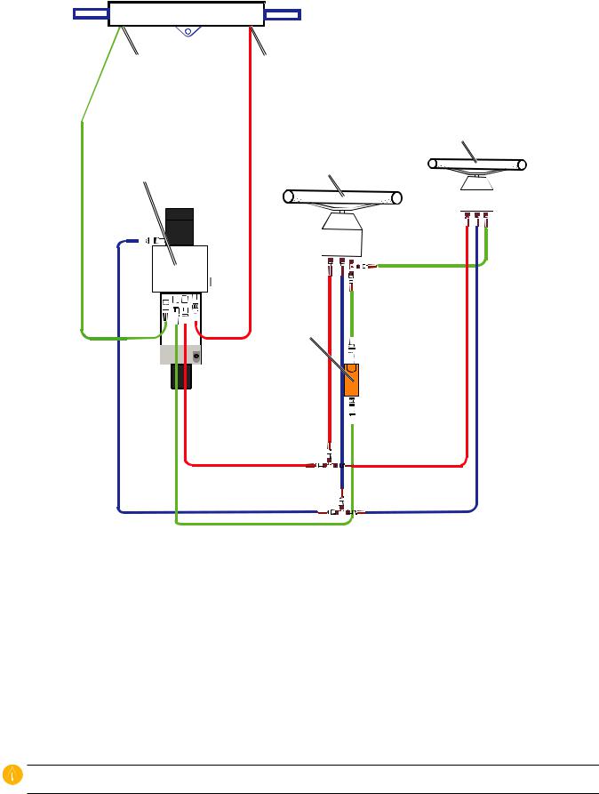
Electrical/Data Connection and Mounting Considerations
The GHP 10 components connect to each other and to power using the included cables. Ensure that the correct cables reach each component, and that each component is in an acceptable location, before mounting any components. Read the following considerations and consult the diagram on the next page before you begin installation.
The Pump and the ECU
•The pump must be located within 19 in. (0.5 m) of the ECU, mounted horizontally if possible. If you cannot mount the pump horizontally, do not mount the pump vertically with the pump head (connectors) down.
•The cables from the pump to the ECU cannot be extended.
•The ECU power cable connects to the boat battery.
The CCU and the ECU
•Do not mount the CCU or the ECU in a location where they will be submerged or exposed to wash-down.
•Mount the CCU in the forward half of the boat, no higher than 10 ft. (3.05 m) above the waterline.
•You can mount the CCU below the waterline, as long as it is not in a location where it will be submerged or exposed to washdown.
•Mount the CCU bracket on a vertical surface or under a horizontal surface, so that the connected wires hang straight down.
•Do not mount the CCU near magnetic material, magnets (speakers and electric motors), or high-current wires. Mount the CCU at least 24 in. (0.61 m) away from movable or changing magnetic disturbances such as anchors, anchor chain, wiper motors, tool boxes, and the autopilot pump. Use a handheld compass to test for magnetic interference in the area.
•The CCU/ECU interconnect cable connects the CCU to the ECU, and is 91/2 ft. (3 m) long. If you cannot mount the CCU within 91/2 ft. (3 m) of the ECU, extension cables are available in lengths of 161/2 ft. (5 m) and 49 ft. (15 m). (See page 4).
•The CCU/ECU interconnect cable connects the CCU to the Shadow Drive, the alarm buzzer, the tachometer of the boat, and the yellow CCU signal wire of the GHC 10 using wires with bare ends. See page 17 for wiring instructions and diagrams.
The CCU and the GHC 10
•The CCU and the GHC 10 connect to a NMEA 2000 network. If you do not have a NMEA 2000 network on your boat, the equipment necessary to build one is provided. For instructions on setting up the NMEA 2000 network, see page 21.
•You can connect an optional NMEA 2000-compatible GPS device to the NMEA 2000 network to use waypoint and route data with the GHP 10.
The GHC 10
•Wire the GHC 10 to the battery of the boat and to the yellow CCU signal wire of the CCU/ECU interconnect cable.
•If you do not have an optional NMEA 2000-compatible GPS device, you can wire an optional NMEA 0183-compatible GPS device to the power/data cable of the GHC 10 instead (see page 23).
The Shadow Drive
•Install the Shadow Drive closer to the helm than to the pump.
•Mount the Shadow Drive horizontally, as level as possible.
•Mount the Shadow Drive at least 12 in. (0.3 m) away from magnetic material such as speakers and electric motors, including the autopilot pump.
GHP 10 Marine Autopilot System Installation Instructions |
11 |
Loading...