


 Loading...
GMR™ 18 XHD/24 XHD/18 HD+
INSTALLATION
INSTRUCTIONS
Important Safety Information
 WARNING
Failure to follow these warnings, cautions, and notices could result in personal injury, damage to the vessel or device, or poor product performance.
See the Important Safety and Product Information guide in the product box for product warnings and other important information.
The radar transmits electromagnetic energy. To avoid possible personal injury, damage to the vessel or device, or poor product performance, ensure that the radar is installed according to the recommendations in these instructions and that all personnel are clear of the path of the radar beam before transmitting. When properly installed and operated, the use of this radar conforms to the requirements of ANSI/IEEE C95.1-1992 Standard for Safety Levels with Respect to Human Exposure to Radio Frequency Electromagnetic Fields.
To avoid possible personal injury, do not look directly at the antenna at close range when the radar is transmitting. Eyes are the most sensitive part of the body to electromagnetic energy.
When connecting the power cable, do not remove the in-line fuse holder. To prevent the possibility of injury or product damage caused by fire or overheating, the appropriate fuse must be in place as indicated in the product specifications. In addition, connecting the power cable without the appropriate fuse in place voids the product warranty.
 CAUTION
This device should be used only as a navigational aid. Using the device for any purpose requiring precise measurement or direction, distance, location, or topography may result in personal injury or damage to the vessel.
To avoid possible personal injury, always wear safety goggles, ear protection, and a dust mask when drilling, cutting, or sanding.
Opening the device may result in personal injury and/or damage to the device. This device contains no user-serviceable parts, and should be opened only by a Garmin® authorized service technician. Any damage resulting from opening the unit by anyone other than a Garmin authorized service technician will not be covered by the Garmin warranty.
•4 mm (13/32 in.) hex wrench
•13 mm (1/2 in.) wrench and torque wrench
•Marine sealant
Mounting Considerations
To complete the installation, you need the appropriate fasteners, tools, and mounts. These items are available at most marine dealers.
•It is highly recommended that the device is mounted out of range of personnel, with the horizontal beam width above head height. To avoid exposure to harmful radio frequency (RF) levels, the device should not be mounted closer to people than the maximum safe distance value listed in the product specifications.
•The device should be mounted high above the ship’s keel line with minimal blockage between the vessel and the radar beam. Obstructions may cause blind and shadow sectors, or generate false echoes. The higher the installation position, the farther the radome can detect targets.
•The device should be mounted on a flat surface or a platform that is parallel to the vessel's water line and is sturdy enough to support the device's weight. The weight for each model is listed in the product specifications.
•Most radar beams spread vertically 12.5° above  and 12.5° below
  the radome's radiating element. On vessels with higher bow angles at cruise speed, the installation angle can be lowered to point the beam slightly downward to the waterline while at rest. Use shims if necessary.
•The radome has two mounting options when installed on a standard marine mount. One mounting option is closer to the
center of the radome  , and the second option is offset towards the back
  to move the radar further away from the mast.
NOTICE
When drilling or cutting, always check what is on the opposite side of the surface to avoid damaging the vessel.
Software Update
You must update the Garmin chartplotter software when you install this device. For instructions on updating the software, see your chartplotter owner's manual at support.garmin.com.
Tools Needed
•Drill
•9.5 mm (3/8 in.) drill bit
•32 mm (1 1/4 in.) drill bit (optional)
•The device should be mounted away from heat sources such as smoke stacks and lights.
2302 


 TA-2013/1848
August 2020 |
GUID-FEFFD103-E5C5-42E2-9628-C69074C658E1 v5 |
•The device should be mounted at a different level than horizontal spreaders and mast crosstrees.
•To avoid interference with a magnetic compass, the device should not be mounted closer to a compass than the compass-safe distance value listed in the product specifications.
•Other electronics and cables should be mounted more than 2 m (6 ½ ft.) from the radar beam path.
•GPS antennas should be either above or below the radar beam path.
•The device should be mounted at least 1 m (40 in.) from any transmitting equipment.
•The device should be mounted at least 1 m (40 in.) away from cables carrying radio signals such as VHF radios, cables, and antennas.
For Single Side Band (SSB) radios, increase the distance to 2 m (6 ½ ft.).
Mounting the Radar
Before you mount the radar, you must review the mounting location considerations and select a mounting location.
NOTE: The supplied M8 x 1.25 x 60 threaded rods can be used
on mounting thicknesses of 5 to 30 mm (3/16 to 1 3/16 in.) (recommended). For surfaces over 30 mm (1 3/16 in.), use longer
threaded rods.
1If you are not installing the device on a pre-drilled Garmin
compatible radar mount, use the included mounting template to drill four 9.5 mm (3/8 in.) mounting holes.
2Connect the power cable to the power port  and the network cable to the network port
  .
.
3Press the cables into any of the guide grooves  on the bottom of the case, and secure them using a cable holddown plate
  .
.
The cables should be bent or twisted as little as possible.
4Using the arrow on the bottom as a reference, position the radome on the mounting surface aligned to the front of the vessel.
NOTE: If you choose not to align the dome with the front of the vessel, you can adjust the front-of-boat offset after the dome is installed (Setting the Front-of-Boat Offset,
page 3).
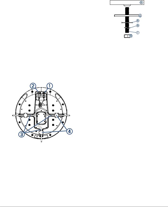
5Apply the included anti-seize compound to the threads of the four M8 x 1.25 x 60 threaded rods.
6Insert the four threaded rods into the mounting holes on the bottom of the radome.
Up to 50 mm (2 in.) of the threaded rods may extend below the radome.
7Apply a bead of marine sealant on the mounting surface around each mounting hole.
8Fasten the radome  to the mounting surface
  using the threaded rods
  , flat washers
  , spring washers
  , and hex nuts
  .
.
9Using a torque wrench, tighten the nuts to 13.7 to 18.6 N-m (10 to 14 lbf-ft.).
Cable Considerations
It may be necessary to drill 32 mm (11/4) in. holes for routing the power or network cables.
•When routing both the power and network cables through the same hole, you must route the network cable before the power cable.
•You must apply marine sealant to the hole after the cables are in place to ensure a waterproof seal.
If the routing hole must be made in a visible location, decorative cable grommets can be purchased from Garmin or a Garmin dealer (optional).
•If needed, the grommet can be trimmed to enable you to route both the network and the power cable through the same hole.
•The optional grommet does NOT provide a waterproof seal. You must apply marine sealant to the grommet after the cables are in place to ensure a waterproof seal.
When installing the network and power cables, you should observe these considerations.
•Cutting the Garmin Marine Network cable is not recommended, but a field install kit can be purchased from Garmin or a Garmin dealer if cutting the network cable is necessary.
•To ensure safety, appropriate tie-wraps, fasteners, and sealant should be used to secure the cable along the route and through any bulkheads or the deck.
•Cables should not be run near moving objects and high-heat sources or through doorways and bilges.
•To avoid interference with other equipment, network and power cables should not be run next to or parallel to other cables, such as radio antenna lines or power cables. If this is not possible, the cables should be shielded with metal conduit or a form of EMI shielding.
•The power cable should be installed as close to the battery source as possible.
◦If it is necessary to extend the power cable, the appropriate gauge of wire must be used (Power Cable Extensions, page 3).
◦Incorrectly extended runs of cable may cause the radar to malfunction due to insufficient power transmission.
2
Loading...