


G3000
®
Integrated Avionics System
G3000
Pilot’s Guide
Daher TBM 930
System Software Version 2234.05 or later


Copyright © 2016, 2020 Garmin Ltd. or its subsidiaries. All rights reserved.
This manual reflects the operation of System Software version 2234.05 or later for the Daher TBM 930. Some differences in operation may be
observed when comparing the information in this manual to earlier or later software versions.
Garmin International, Inc.
1200 East 151st Street
Olathe, Kansas 66062, U.S.A.
Garmin AT, Inc.
2345 Turner Road SE
Salem, OR 97302, U.S.A.
Garmin (Europe) Ltd.
Liberty House, Hounsdown Business Park
Southampton, Hampshire SO40 9LR U.K.
Garmin Corporation
No. 68, Zhangshu 2nd Road
Xizhi District, New Taipei City, Taiwan
Contact Garmin Product Support or view warranty information at flygarmin.com.
Except as expressly provided herein, no part of this manual may be reproduced, copied, transmitted, disseminated, downloaded or stored in any
storage medium, for any purpose without the express written permission of Garmin. Garmin hereby grants permission to download a single copy
of this manual and of any revision to this manual onto a hard drive or other electronic storage medium to be viewed for personal use, provided
that such electronic or printed copy of this manual or revision must contain the complete text of this copyright notice and provided further that any
unauthorized commercial distribution of this manual or any revision hereto is strictly prohibited.
Garmin® and G3000®, WATCH®, FliteCharts®, Connext® and SafeTaxi® are registered trademarks of Garmin Ltd. or its subsidiaries. These
trademarks may not be used without the express permission of Garmin.
NavData® is a registered trademark of Jeppesen, Inc.; Stormscope® is a registered trademark of L-3 Communications. SiriusXM Weather and
SiriusXM Satellite Radio are provided by SiriusXM Satellite Radio, Inc.
AC-U-KWIK® is a registered trademark of Penton Business Media
Inc. NavData® is a registered trademark of Jeppesen, Inc.; Wi-Fi® is a registered trademark of the Wi-Fi Alliance. The Bluetooth®
word mark and logos are owned by the Bluetooth SIG, Inc. and any use of such marks by Garmin is under license.
AOPA Membership Publications, Inc. and its related organizations (hereinafter collectively “AOPA”) expressly disclaim all warranties,
with respect to the AOPA information included in this data, express or implied, including, but not limited to, the implied warranties
of merchantability and fitness for a particular purpose. The information is provided “as is” and AOPA does not warrant or make any
representations regarding its accuracy, reliability, or otherwise. Under no circumstances including negligence, shall AOPA be liable for
any incidental, special or consequential damages that result from the use or inability to use the software or related documentation, even
if AOPA or an AOPA authorized representative has been advised of the possibility of such damages. User agrees not to sue AOPA and, to
the maximum extent allowed by law, to release and hold harmless AOPA from any causes of action, claims or losses related to any actual
or alleged inaccuracies in the information. Some jurisdictions do not allow the limitation or exclusion of implied warranties or liability for
incidental or consequential damages so the above limitations or exclusions may not apply to you.
AC-U-KWIK and its related organizations (hereafter collectively “AC-U-KWIK Organizations”) expressly disclaim all warranties with
respect to the AC-U-KWIK information included in this data, express or implied, including, but not limited to, the implied warranties of
merchantability and fitness for a particular purpose. The information is provided “as is” and AC-U-KWIK Organizations do not warrant or
make any representations regarding its accuracy, reliability, or otherwise. Licensee agrees not to sue AC-U-KWIK Organizations and, to
the maximum extent allowed by law, to release and hold harmless AC-U-KWIK Organizations from any cause of action, claims or losses
related to any actual or alleged inaccuracies in the information arising out of Garmin’s use of the information in the datasets. Some
jurisdictions do not allow the limitation or exclusion of implied warranties or liability for incidental or consequential damages so the
above limitations or exclusions may not apply to licensee.
Printed in the U.S.A
190-02046-02 Rev. A
Garmin G3000 Pilot’s Guide for the Daher TBM 930

Blank Page
Garmin G3000 Pilot’s Guide for the Daher TBM 930
190-02046-02 Rev. A
WARNINGS, CAUTIONS, AND NOTES
WARNING: Do not operate this equipment without first obtaining qualified instruction.
WARNING: Always refer to current aeronautical charts and NOTAMs for verification of displayed aeronautical
information. Displayed aeronautical data may not incorporate the latest NOTAM information.
WARNING: Do not use geometric altitude for compliance with air traffic control altitude requirements. The
primary barometric altimeter must be used for compliance with all air traffic control altitude regulations,
requirements, instructions, and clearances.
WARNING: Do not use basemap information (land and water data) as the sole means of navigation.
Basemap data is intended only to supplement other approved navigation data sources and should be
considered only an aid to enhance situational awareness.
WARNING: Do not rely solely upon the display of traffic information to accurately depict all of the traffic
within range of the aircraft. Due to lack of equipment, poor signal reception, and/or inaccurate information
from aircraft or ground stations, traffic may be present that is not represented on the display.
WARNING: Do not use data link weather information for maneuvering in, near, or around areas of
hazardous weather. Information contained within data link weather products may not accurately depict
current weather conditions.
WARNING: Do not use the indicated data link weather product age to determine the age of the weather
information shown by the data link weather product. Due to time delays inherent in gathering and processing
weather data for data link transmission, the weather information shown by the data link weather product
may be older than the indicated weather product age.
WARNING: Do not use terrain avoidance displays as the sole source of information for maintaining
separation from terrain and obstacles. Garmin obtains terrain and obstacle data from third party sources
and cannot independently verify the accuracy of the information.
WARNING: Do not rely on the displayed minimum safe altitude (MSAs) as the sole source of obstacle
and terrain avoidance information. Always refer to current aeronautical charts for appropriate minimum
clearance altitudes.
WARNING: Do not use GPS to navigate to any active waypoint identified as a ‘NON WGS84 WPT’ by a
system message. ‘NON WGS84 WPT’ waypoints are derived from an unknown map reference datum that
may be incompatible with the map reference datum used by GPS (known as WGS84) and may be positioned
in error as displayed.
190-02046-02 Rev. A
Garmin G3000 Pilot’s Guide for the Daher TBM 930
WARNINGS, CAUTIONS, AND NOTES
WARNING: Do not rely on the autopilot to level the aircraft at the MDA/DH when flying an approach with
vertical guidance. The autopilot will not level the aircraft at the MDA/DH even if the MDA/DH is set in the
altitude preselect.
WARNING: Do not rely on the accuracy of attitude and heading indications in the following geographic
areas (due to variations in the earth’s magnetic field): North of 72° North latitude at all longitudes; South
of 70° South latitude at all longitudes; North of 65° North latitude between longitude 75° W and 120° W.
(Northern Canada); North of 70° North latitude between longitude 70° W and 128° W. (Northern Canada);
North of 70° North latitude between longitude 85° E and 114° E. (Northern Russia); South of 55° South
latitude between longitude 120° E and 165° E. (Region south of Australia and New Zealand).
WARNING: Use appropriate primary systems for navigation, and for terrain, obstacle, and traffic avoidance.
Garmin SVT is intended as an aid to situational awareness only and may not provide either the accuracy or
reliability upon which to solely base decisions and/or plan maneuvers to avoid terrain, obstacles, or traffic.
WARNING: Do not use the Garmin SVT runway depiction as the sole means for determining the proximity
of the aircraft to the runway or for maintaining the proper approach path angle during landing.
WARNING: Do not operate the weather radar in a transmitting mode when personnel or objects are within
the MPEL boundary.
WARNING: Always position the weather radar gain setting to Calibrated for viewing the actual intensity of
precipitation. Changing the gain in weather mode causes precipitation intensity to be displayed as a color
not representative of the true intensity.
WARNING: Do not consider the overflight of thunderstorms to be safe, as extreme turbulence may exist
significantly above observed returns.
WARNING: Do not assume weather radar transmission is disabled unless all display panes displaying
weather radar are set to Standby Mode, and are displaying ‘STANDBY’ in the center of each weather radar
display. Transmission is also disabled by touching the Radar On Button or pressing the Radar On Softkey to
set the weather radar system to Off Mode, as indicated by a gray annunciator.
WARNING: Do not rely only on the Turbulence Detection function for hazardous weather avoidance, or to
maneuver in, near, or around areas of hazardous weather.
WARNING: Do not rely on information from a lightning detection system display as the sole basis for
hazardous weather avoidance. Range limitations and interference may cause the system to display inaccurate
or incomplete information. Refer to documentation from the lightning detection system manufacturer for
detailed information about the system.
Garmin G3000 Pilot’s Guide for the Daher TBM 930
190-02046-02 Rev. A

WARNINGS, CAUTIONS, AND NOTES
WARNING: Do not use TAWS information for primary terrain or obstacle avoidance. TAWS is intended only
to enhance situational awareness.
WARNING: Do not rely solely upon the display of traffic information for collision avoidance maneuvering.
The traffic display does not provide collision avoidance resolution advisories and does not under any
circumstances or conditions relieve the pilot’s responsibility to see and avoid other aircraft.
WARNING: Do not use a QFE altimeter setting with this system. System functions will not operate properly
with a QFE altimeter setting. Use only a QNH altimeter setting for height above mean sea level, or the
standard pressure setting, as applicable.
WARNING: Do not use SurfaceWatch™ information as the primary method of flight guidance during
airborne or ground operations. SurfaceWatch does not have NOTAM or ATIS information regarding the
current active runway, condition, or information about the position of hold lines.
CAUTION: Do not clean display surfaces with abrasive cloths or cleaners containing ammonia. They will
harm the anti-reflective coating.
CAUTION: Do not allow repairs to be made by anyone other than an authorized Garmin service center.
Unauthorized repairs or modifications could void both the warranty and affect the airworthiness of the
aircraft.
CAUTION: Never disconnect power to the system when loading a database. Power interruption during the
database loading process could result in maintenance being required to reboot the system.
CAUTION: Avoid areas on the radar display that appear “shadowed” (gray). The accuracy of the intensity
of returns in the shaded areas should be treated as suspect. Exercise extreme caution, making maneuvering
decisions with this information in mind.
CAUTION: When all display panes displaying weather radar are set to Standby Mode, the antenna is parked
at the center line. It is always a good idea to put the radar in Standby Mode before taxiing the aircraft to
prevent the antenna from bouncing on the bottom stop and possibly causing damage to the radar assembly.
NOTE All visual depictions contained within this document, including screen images of the system panel
and displays, are subject to change and may not reflect the most current system and aviation databases.
Depictions of equipment may differ slightly from the actual equipment.
NOTE: Do not rely solely upon data link services to provide Temporary Flight Restriction (TFR) information.
Always confirm TFR information through official sources such as Flight Service Stations or Air Traffic Control.
190-02046-02 Rev. A
Garmin G3000 Pilot’s Guide for the Daher TBM 930

WARNINGS, CAUTIONS, AND NOTES
NOTE: The United States government operates the Global Positioning System and is solely responsible for
its accuracy and maintenance. The GPS system is subject to changes which could affect the accuracy and
performance of all GPS equipment. Portions of the system utilize GPS as a precision electronic NAVigation
AID (NAVAID). Therefore, as with all NAVAIDs, information presented by the system can be misused or
misinterpreted and, therefore, become unsafe.
NOTE: This device complies with part 15 of the FCC Rules. Operation is subject to the following two
conditions: (1) this device may not cause harmful interference, and (2) this device must accept any
interference received, including interference that may cause undesired operation.
NOTE: Use of polarized eyewear may cause the flight displays to appear dim or blank.
NOTE: This product, its packaging, and its components contain chemicals known to the State of California
to cause cancer, birth defects, or reproductive harm. This notice is being provided in accordance with
California’s Proposition 65. If you have any questions or would like additional information, please refer to
our web site at www.garmin.com/prop65.
NOTE: Operating the system in the vicinity of metal buildings, metal structures, or electromagnetic fields
can cause sensor differences that may result in nuisance miscompare annunciations during start up, shut
down, or while taxiing. If one or more of the sensed values are unavailable, the annunciation indicates no
comparison is possible.
NOTE: The system responds to a terminal procedure based on data coded within that procedure in the
Navigation Database. Differences in system operation may be observed among similar types of procedures
due to differences in the Navigation Database coding specific to each procedure.
NOTE: The FAA has asked Garmin to remind pilots who fly with Garmin database-dependent avionics of the
following:
It is the pilot’s responsibility to remain familiar with all FAA regulatory and advisory guidance and information
related to the use of databases in the National Airspace System.
Garmin equipment will only recognize and use databases that are obtained from Garmin or Jeppesen. Databases
obtained from Garmin or Jeppesen that have a Type 2 Letter of Authorization (LOA) from the FAA are assured
compliance with all data quality requirements (DQRs). A copy of the Type 2 LOA is available for each applicable
database and can be viewed at flygarmin.com by selecting ‘Aviation Database Declarations.’
Use of a current Garmin or Jeppesen database in your Garmin equipment is required for compliance with
established FAA regulatory guidance, but does not constitute authorization to fly any and all terminal procedures
that may be presented by the system. It is the pilot’s responsibility to operate in accordance with established
pertinent aircraft documents and regulatory guidance or limitations as applicable to the pilot, the aircraft, and
installed equipment.
Garmin G3000 Pilot’s Guide for the Daher TBM 930
190-02046-02 Rev. A

WARNINGS, CAUTIONS, AND NOTES
NOTE: The pilot/operator must review and be familiar with Garmin’s database exclusion list as discussed
in SAIB CE-14-04 to determine what data may be incomplete. The database exclusion list can be viewed at
flygarmin.com by selecting ‘Database Exclusions List.’
NOTE: The pilot/operator must have access to Garmin and Jeppesen database alerts and consider their
impact on the intended aircraft operation. The database alerts can be viewed at flygarmin.com by selecting
‘Aviation Database Alerts.’
NOTE: If the pilot/operator wants or needs to adjust the database, contact Garmin Product Support.
NOTE: Garmin requests the flight crew report any observed discrepancies related to database information.
These discrepancies could come in the form of an incorrect procedure; incorrectly identified terrain, obstacles
and fixes; or any other displayed item used for navigation or communication in the air or on the ground. Go
to flygarmin.com and select ‘Aviation Data Error Report’.
NOTE: Electronic aeronautical charts displayed on this system have been shown to meet the guidance in AC
120-76D as a Type B Electronic Flight Bag (EFB) for FliteCharts and ChartView. The accuracy of the charts
is subject to the chart data provider. Own-ship position on airport surface charts cannot be guaranteed to
meet the accuracy specified in AC 120-76D. Possible additional requirements may make a secondary source
of aeronautical charts, such as traditional paper charts or an additional electronic display, necessary on the
aircraft and available to the pilot. If the secondary source of aeronautical charts is a Portable Electronic
Device (PED), its use must be consistent with the guidance in AC 120-76D.
NOTE: The navigation databases used in Garmin navigation systems contain Special Procedures. Prior
to flying these procedures, pilots must have specific FAA authorization, training, and possession of the
corresponding current, and legitimately-sourced chart (approach plate, etc.). Inclusion of the Special
Procedure in the navigation database DOES NOT imply specific FAA authorization to fly the procedure.
NOTE: Terrain and obstacle alerting is not available north of 89º North latitude and south of 89º South
latitude. This is due to limitations present within the Terrain database and the system’s ability to process
the data representing the affected areas.
NOTE: The nose of the ‘own ship’ symbol represents the location of the aircraft. The center of any traffic
symbol represents the location of that traffic. The traffic and own ship symbols are an abstract representation
and do not reflect the physical extent of the aircraft/traffic, and should not replace other methods for
identifying traffic.
NOTE: When using Stormscope, there are several atmospheric phenomena in addition to nearby
thunderstorms that can cause isolated discharge points in the strike display mode. However, clusters of
two or more discharge points in the strike display mode do indicate thunderstorm activity if these points
reappear after the screen has been cleared.
190-02046-02 Rev. A
Garmin G3000 Pilot’s Guide for the Daher TBM 930
WARNINGS, CAUTIONS, AND NOTES
NOTE: Intruder aircraft at or below 500 ft. AGL may not appear on the Garmin SVT display or may appear
as a partial symbol.
NOTE: Interference from GPS repeaters operating inside nearby hangars can cause an intermittent loss of
attitude and heading displays while the aircraft is on the ground. Moving the aircraft more than 100 yards
away from the source of the interference should alleviate the condition.
NOTE: Operate G3000 system power through at least one cycle in a period of four days of continuous
operation to avoid an autonomous system reboot.
Garmin G3000 Pilot’s Guide for the Daher TBM 930
190-02046-02 Rev. A

RECORD OF REVISIONS
Record of Revisions
Part Number Revision Date Page Range Description
190-02046-00 A
2/16
All
Production release.
B
190-02046-01 A 5/25 All Added support for HF Radio
190-02046-02 A 5/29/20 All Updated to GDU 20.92
3/16
All
Removed references to Baro-VNAV
Removed reference to takeoff configuration of landing gear and
flaps from the Negative Climb Rate TAWS discussion
Removed references to GDL 59
Removed references to Wi-Fi
Removed APR Advisory System Message
Added Animated NEXRAD for SiriusXM Weather
Added SELCAL
Added other GDU 6.56 parameters
Removed references to CCD VNAV functions.
190-02046-02 Rev. A
Garmin G3000 Pilot’s Guide for the Daher TBM 930

RECORD OF REVISIONS
Blank Page
Garmin G3000 Pilot’s Guide for the Daher TBM 930
190-02046-02 Rev. A

TABLE OF CONTENTS
SECTION 1 SYSTEM OVERVIEW
1.1 System Description ..............................................1
1.2 System Controls ...................................................4
PFD Controls .......................................................................4
Touchscreen Controller ......................................................10
Secure Digital Cards .......................................................... 30
1.3 System Operation ..............................................32
System Power-On .............................................................. 32
Normal Operation .............................................................33
Reversionary Display Operation ........................................34
Touchscreen Controller Failure ..........................................35
AHRS Operation ................................................................ 35
GPS Receiver Operation ....................................................37
Annunciations ................................................................... 40
1.4 Initialization ....................................................... 41
1.5 System Management .........................................43
Avionics Settings ............................................................... 43
Avionics Status..................................................................53
SiriusXM Information ........................................................ 54
1.6 Utilities...............................................................55
Timer .................................................................................55
Trip Statistics ..................................................................... 56
Scheduled Messages ......................................................... 60
Screen Cleaning ................................................................61
Crew Profiles ..................................................................... 61
1.7 Display Backlighting ..........................................64
2.4 PFD Annunciations and Alerting Functions ...... 108
Marker Beacon Annunciations ........................................108
Altitude Alerting .............................................................. 108
Low Altitude Annunciation .............................................. 109
Minimum Altitude Alerting .............................................. 109
Radio Altimeter (RA) ....................................................... 110
2.5 Abnormal Operations .......................................112
Abnormal GPS Conditions ............................................... 112
Comparator Annunciations .............................................113
Reversionary Sensor Annunciations ................................114
Garmin SVT Troubleshooting ...........................................115
Unusual Attitudes ...........................................................115
SVT Unusual Attitudes ....................................................116
SECTION 3 ENGINE INDICATION & CREW ALERTING
SYSTEMS
3.1 Engine Indication System (EIS) ........................118
3.2 Synoptics .......................................................... 124
Electrical System .............................................................125
Fuel System ..................................................................... 128
General Systems .............................................................129
3.3 Landing Field Elevation ...................................131
3.4 Crew Alerting System (CAS) ............................. 132
CAS Messages and Prioritization ....................................133
3.5 Reversionary Mode ..........................................134
SECTION 4 AUDIO AND CNS
SECTION 2 FLIGHT INSTRUMENTS
2.1 Flight Instruments .............................................. 68
Airspeed Indicator ............................................................. 68
Attitude Indicator .............................................................. 70
Altimeter ........................................................................... 71
Vertical Speed Indicator (VSI) ............................................74
Vertical Deviation Indicator (VDI) ......................................75
Horizontal Situation Indicator (HSI) ................................... 78
2.2 Garmin SVT (Synthetic Vision Technology) ......... 92
SVT Operation ................................................................... 93
SVT Features .....................................................................95
Field of View ...................................................................103
2.3 Supplemental Flight Data ................................104
Temperature Displays ...................................................... 104
Generic Timer ..................................................................104
Wind Data ....................................................................... 105
Angle of Attack (AOA) Indicator ...................................... 106
Vertical Navigation (VNV) Indications .............................107
4.1 Overview .......................................................... 135
Touchscreen Controller Audio and CNS Controls .............136
PFD COM/NAV display ....................................................138
MFD COM display ........................................................... 139
COM Transceiver Selection and Activation ......................140
COM Frequency Tuning ...................................................143
Frequency Spacing ..........................................................151
Automatic Squelch .......................................................... 152
Volume ............................................................................153
HF COM Transceiver ........................................................155
SELCAL ............................................................................ 156
4.2 NAV Operation ................................................. 159
NAV Radio Selection and Activation................................159
NAV Receiver Tuning ....................................................... 160
Marker Beacon Receiver .................................................168
ADF/DME Tuning ............................................................. 170
4.3 Transponder(s) .................................................176
Transponder Controls ...................................................... 176
Transponder Selection ..................................................... 177
190-02046-02 Rev. A i
Garmin G3000 Pilot’s Guide for the Daher TBM 930

TABLE OF CONTENTS
Transponder Mode Selection ........................................... 177
Entering a Transponder Code ..........................................180
IDENT Function ...............................................................181
4.4 Additional Audio Functions ..............................182
Mono/Stereo Headsets .................................................... 182
Speaker ...........................................................................182
Intercom ..........................................................................182
Passenger Address (PA) System .......................................186
Clearance Recorder and Player .......................................186
3D Audio ......................................................................... 188
Simultaneous COM Operation ........................................189
Auxiliary Audio ...............................................................190
Audio Feedback (Clicks) ..................................................192
Telephone (TEL) ...............................................................193
4.5 Abnormal Operation ........................................194
Stuck Microphone ........................................................... 194
COM Failure ....................................................................194
COM Tuning Failure .........................................................195
Audio Controller Fail-Safe Operation ..............................195
Touchscreen Controller Failure ........................................195
SECTION 5 FLIGHT MANAGEMENT
5.1 Introduction .....................................................197
Navigation Status Box / MFD Navigation Data Bar ......... 199
5.2 Using Map Displays .......................................... 201
Map Settings Synchronization ......................................... 201
Map Orientation .............................................................202
Map Range .....................................................................204
Map Panning ...................................................................206
Measuring Bearing and Distance ....................................210
Absolute Terrain .............................................................. 212
Map Symbols ..................................................................215
Airways ...........................................................................221
Additional Navigation Map Items ................................... 222
5.3 Waypoints ........................................................227
Airports ........................................................................... 227
Non-Airport and User Created Waypoints ....................... 233
5.4 Airspaces ..........................................................242
Nearest Airspace ............................................................. 243
Smart Airspace ................................................................ 246
5.5 Direct-to Navigation .......................................247
5.6 Flight Planning ................................................. 252
Introduction ....................................................................252
Creating a Flight Plan .....................................................257
Flight Plan Waypoint and Airway Modifications ..............259
Flight Plan Operations ....................................................271
Managing Flight Plans ....................................................287
5.7 Vertical Navigation ..........................................295
Constraints ...................................................................... 296
Vertical Situation Display ................................................300
5.8 Procedures .......................................................307
Preview Only Procedures ................................................309
Departures ......................................................................310
Arrivals ...........................................................................313
Approaches ..................................................................... 315
5.9 Trip Planning ....................................................328
Trip Statistics ................................................................... 329
Fuel Statistics .................................................................. 330
Other Statistics ................................................................ 330
5.10 Weight and Fuel Planning ................................332
Weight Caution And Warning Conditions ........................336
5.11 Abnormal Operation ........................................337
Dead Reckoning Navigation ............................................337
SECTION 6 HAZARD AVOIDANCE
6.1 Data Link Weather............................................340
Activating Data Link Weather Services ............................ 341
Registering the system for Garmin Connext Services ...... 342
Accessing FIS-B Weather Information .............................342
Weather Product Age ...................................................... 344
Displaying Data Link Weather Products ..........................348
Connext Weather Data Requests .....................................355
Weather Product Overview .............................................359
Data Link Weather Products ............................................ 371
FIS-B Weather Abnormal Operations ............................... 394
Garmin Connext Abnormal Operations ...........................395
6.2 Stormscope Lightning Detection System ......... 396
Using the Stormscope Pane .............................................396
Stormscope Information on Navigation Maps ................. 399
Abnormal Operations ...................................................... 402
System Status..................................................................402
6.3 Airborne Color Weather Radar ......................... 403
System Description .......................................................... 403
Principles of Airborne Weather Radar..............................403
NEXRAD and Airborne Weather Radar ............................ 404
Antenna Beam Illumination ............................................405
Safe Operating Distance .................................................410
Basic Antenna Tilt and Range Setup ................................411
Weather Display And Interpretation ................................ 414
Ground Mapping and Interpretation ............................... 428
Additional Radar Displays ............................................... 429
System Status..................................................................435
6.4 Vertical Situation Display Terrain .....................437
VSD Inset Window...........................................................439
Track Mode Boundary ..................................................... 440
Garmin G3000 Pilot’s Guide for the Daher TBM 930
190-02046-02 Rev. Aii

TABLE OF CONTENTS
6.5 Terrain Displays ................................................ 442
Relative Terrain Symbology .............................................443
Displaying Relative Terrain Information ..........................445
Terrain Pane ....................................................................445
Terrain-SVT and TAWS-B Terrain And Obstacle alerts ......449
Forward Looking Terrain Avoidance ................................451
Additional TAWS-B Alerting ............................................454
System Status..................................................................456
TAWS-B Abnormal operations ......................................... 458
6.6 Traffic Information Service (TIS) ......................460
Traffic Map Pane .............................................................461
Displaying Traffic Data on Navigation Maps ...................462
TIS Alerts ......................................................................... 464
Additional Traffic Displays ............................................... 466
System Status..................................................................467
6.7 Traffic Advisory System (TAS) ...........................469
Theory of Operation ........................................................469
Traffic Alerts .................................................................... 473
Operations ......................................................................476
Additional Traffic Displays ............................................... 477
6.8 ADS-B Traffic ....................................................481
ADS-B System Overview .................................................481
ADS-B Traffic Advisory System (ATAS) .............................484
Airborne and Surface Applications ..................................485
Operation ........................................................................ 486
System Status..................................................................491
SECTION 7 AUTOMATIC FLIGHT CONTROL SYSTEM
7.1 Overview .......................................................... 495
Basic Autopilot Operation ............................................... 496
AFCS Preflight Test (PFT) .................................................496
7.2 AFCS Controls ..................................................497
AFCS Controller ............................................................... 497
Additional AFCS Controls ................................................ 498
7.3 Flight Director Operation .................................499
Activating the Flight Director ..........................................499
AFCS Status Box..............................................................500
Flight Director Modes......................................................500
Flight Director Selection .................................................. 501
Command Bars ...............................................................501
LEVEL MODE ................................................................... 502
7.4 AFCS Modes .....................................................503
Vertical Modes ................................................................503
Lateral Modes ................................................................. 509
Combination Modes ........................................................ 514
7.5 Autopilot and Yaw Damper Operation .............525
Flight Control .................................................................. 525
Engaging the Autopilot and Yaw Damper .......................526
Control Wheel Steering (CWS) ........................................526
Disengaging the Autopilot and Yaw Damper ...................526
7.6 AFCS Annunciations and Alerts ........................ 528
AFCS Status Alerts...........................................................528
7.7 Abnormal Operation ........................................529
Suspected Autopilot Malfunction .................................... 529
Overpowering Autopilot Servos ......................................529
Overspeed Protection ...................................................... 529
Underspeed Protection .................................................... 530
Emergency Descent Mode ............................................... 532
SECTION 8 ADDITIONAL FEATURES
8.1 Overview .......................................................... 533
8.2 SafeTaxi (Optional) ...........................................534
8.3 SurfaceWatch (Optional) ..................................537
Information Display ......................................................... 538
Alerts ..............................................................................538
SurfaceWatch Setup ........................................................540
8.4 Electronic Charts ..............................................542
ChartView (Optional) ......................................................543
FliteCharts ....................................................................... 549
8.5 Satellite Telephone and Datalink Services (Optional) 556
Registering the System with Garmin Connext ................. 556
Contacts .......................................................................... 557
Telephone Communication (Optional) .............................560
Text Messaging (SMS) ..................................................... 567
8.6 Connext Setup (Optional) ................................577
8.7 SiriusXM Satellite Radio (Optional) .................581
Activating SiriusXM Satellite Services .............................581
Using SiriusXM Radio ...................................................... 582
8.8 Data Logging ...................................................586
Flight Data Logging.........................................................586
CMC Data Logging (Optional) ......................................... 587
8.9 Electronic Checklists (Optional) .......................588
Checklist features............................................................588
Operation ........................................................................ 589
8.10 Electronic Documents (Optional) ..................... 593
Installed Documents .......................................................593
User Documents .............................................................. 593
Viewing Electronic Documents ........................................593
190-02046-02 Rev. A iii
Garmin G3000 Pilot’s Guide for the Daher TBM 930

TABLE OF CONTENTS
8.11 Electronic Stability & Protection (ESP) (Optional) 601
Roll Engagement ............................................................. 601
Pitch Engagement ........................................................... 603
Angle of Attack Protection ..............................................604
High Airspeed Protection ................................................605
8.12 Database Cycle Number and Revisions ............606
Cycle Number and Revision ............................................606
8.13 Abnormal Operation ........................................609
Datalink Troubleshooting ................................................609
APPENDICES
Annunciations and Alerts .........................................611
CAS (Crew Alerting System) Messages............................611
VOICE Alerts ....................................................................613
System Message Annunciations ...................................... 614
System Messages ............................................................ 615
Database Management ............................................631
Loading Updated Databases ...........................................632
Database Updates Using a Supplemental Data Card ......633
Database Updates Using The Wireless Transceiver .......... 636
Database Synchronization Feature ................................641
Database Deletion Feature ............................................642
Magnetic Field Variation Database Update .....................643
Aviation Terms and Acronyms...................................647
Frequently Asked Questions ..................................... 659
INDEX
Index ......................................................................... I-1
Garmin G3000 Pilot’s Guide for the Daher TBM 930
190-02046-02 Rev. Aiv

SYSTEM OVERVIEW
SECTION 1 SYSTEM OVERVIEW
1.1 SYSTEM DESCRIPTION
This section provides an overview of the Garmin G3000 as installed in the Daher TBM 930 aircraft. It is
integrated flight control system that presents flight instrumentation, position, navigation, communication, and
identification information to the flight crew using flat-panel color displays and Touchscreen Controllers. The
system consists of the following Line Replaceable Units (LRUs):
• GDU 1200W (3) – Each GDU is configured as one of two Primary Flight Displays (PFDs) or one Multi-
function Display (MFD). The GDU 1200W features a 12-inch light emitting diode (LED) backlit widescreen
display with a 1280 x 800 resolution. The unit installed on the left/pilot side is designated as PFD1, and the
one installed on the right/copilot side is designated as PFD2. The unit installed in the center is designated as
the MFD. The displays communicate with each other and the Touchscreen Controllers through a High-Speed
Data Bus (HSDB) Ethernet connection
• GTC 580 (2)
to FMS functions, data entry capability, and communications control to the system. The unit installed on the
left/pilot side is designated as GTC1, and the one installed on the right/copilot side is designated as GTC2. Each
touchscreen controller communicates with the on-side PFD, the MFD. GTC1 communicates with the GMA 36
using an HDSB connection.
• GMA 36 (1)
intercom, and marker beacon audio. The GMA 36 is connected to GTC1 using an HSDB interface and to the
each IAU using an RS-232 and digital audio connections.
• GIA 63W
LRUs with each on-side GDU 1200W. Each IAU contains a GPS Satellite-Based Augmentation System (SBAS)
receiver, a very high frequency (VHF) communication/navigation/glideslope (COM/NAV/GS) receiver, a Flight
Director (FD) and system integration microprocessors. The IAUs communicate with each other through using
usign HSDB and additional backup paths.
• GDC 74B – Processes data from the pitot/static system as well as the OAT probe. This unit provides pressure
altitude, airspeed, vertical speed and OAT information to the G3000 system, and it communicates with the on-
side GIA 63W, on-side GDU 1200W and on-side GRS 77, using an ARINC 429 digital interface (it also interfaces
directly with the OAT). The GDC 74B is designed to operate in Reduced Vertical Separation Minimum (RVSM)
airspace.
• GEA 71 (2)
This unit communicate with both IAUs using an RS-485 digital interface.
• GTX 33 with ES
with ES
figure). These solid-state transponders provide Modes A/C/S and ADS-B Out capability. The GTX 345R also
provides ADS-B In capability. The GTX 33 with ES and GTX 33D with ES feature extended squitter capabilities.
The GTX 33D also features diversity. The transponder(s) communicate with the onside IAU(s).
• GRS 77
information via ARINC 429 protocol to the on-side and cross-side IAU, and to the on-side GDU 1200W. An
RS-232 backup path connects each AHRS to each IAU. The AHRS contains advanced sensors (including
accelerometers and rate sensors) and interfaces with the Magnetometer to obtain magnetic field information,
with the ADC to obtain air data, and with both IAUs to obtain GPS information. AHRS operation is discussed
in System Operation, later in this section.
– The Touchscreen Controller provides MFD control, Display Pane control on the PFD, in addition
– The Remote Audio Unit integrates navigation/communication radio (NAV/COM) digital audio,
(2) – The Integrated Avionics Units (IAU) function as the main communications hub, linking several
– The Engine Airframe Unit receives and processes signals from the engine and airframe sensors.
(1) (standard) GTX 345R (1) (standard)
(1) (optional) or GTX 345R (1) (optional) – One or two transponders are installed (see the following
(2) – The Attitude and Heading Reference System (AHRS) provides aircraft attitude and heading
or GTX 33D with ES
(1) (standard) and
GTX 33
190-02046-02 Rev. A
Garmin G3000 Pilot’s Guide for the Daher TBM 930
1
SYSTEM OVERVIEW
• GMU 44
to determine aircraft magnetic heading. The magnetometer receives power directly from the AHRS and
communicates with it via an RS-485 and RS-232 digital interface.
• GDL 69A SXM (1 optional)
digital audio entertainment. The Data Link Receiver communicates with the MFD via a HSDB connection. A
subscription to SiriusXM Weather and/or SiriusXM Satellite Radio service is required to enable the GDL 69A
capability.
• GMC 710
to PFD1 and PFD2.
• GRA 55 (1 optional)
of radar altitude information.
• GTA 82 – The GTA 82 Trim Adapter is a remote mounted device that is used to allow the AFCS to drive the
yaw trim actuator.
• GTS 820 – The GTS 820 Traffic Advisory System (TAS) uses active interrogations of Mode S and Mode C
transponders to provide Traffic Advisories to the pilot independent of the air traffic control system.
• GSA 81
units interface with each GIA 63W.
• GWX 70 (1 optional) – The GWX 70 provides airborne real-time weather and ground mapped radar data to
the displays. The unit is connected to the MFD with an HSDB connection.
• GSR 56 (1 optional) – The Iridium Transceiver operation for voice communication is by means of pilot and
copilot headsets in the cockpit. The system is also capable of SMS text messaging. Connection to the system
is through the RS-232 bus.
The Daher TBM 930 is also equipped with a Garmin Automated Flight Control System (AFCS), which includes
the Flight Director (FD), Autopilot (AP), manual electric trim, and control wheel steering (CWS) functions of the
G3000 system.
(2) – The Magnetometer measures local magnetic field and sends data to the AHRS for processing
– The Satellite Data Link Radio Receiver receives weather information, as well as
– The AFCS Controller provides AFCS control through an RS-232 digital interface. The unit connects
– The Radar Altimeter provides altitude above the ground information and rate of change
(4) – The GSA 81 servos are used for the automatic control of roll, yaw, pitch, and pitch trim. These
NOTE: Refer to the Automatic Flight Control System (AFCS) Section for details on the Garmin AFCS.
Figure 1-1 shows interconnection of the LRUs.
NOTE: For information on optional equipment not shown in Figure 1-1, consult the applicable optional
interface user’s guide. This document assumes the reader is already familiar with the operation of this
additional equipment
Garmin G3000 Pilot’s Guide for the Daher TBM 930
190-02046-02 Rev. A2

SYSTEM OVERVIEW
BARO Set
#1
GDU 1200W
(PFD1)
#1 GIA 63W
(Integrated
Avionics
Unit)
VHF COM
GPS/SBAS
VOR/LOC
G/S
AFCS Mode
Logic
Flight
Director
Servo
Management
#2 GIA 63W
(Integrated
Avionics
Unit)
VHF COM
GPS/SBAS
VOR/LOC
G/S
AFCS Mode
Logic
Flight
Director
Servo
Management
#2
GDU 1200W
(PFD2)
Non-Garmin Equipment
RA-3502
(ADF)
ELT
FDR
WX-500
(Lightning
Detection)
#1 GTX 33 w/ES
(Transponder)
or
#3
GDU 1200W
(MFD)
#1 GDC 74B
(Air Data
Computer)
#2 GDC 74B
(Air Data
Computer)
#1 GRS 77
(Attitude &
Heading)
#2 GRS 77
(Attitude &
Heading)
Optional
Garmin Equipment
Optional
Non-Garmin Equipment
AOA Computer
KN-63
(DME)
#1 GMU 44
(Magnetometer)
#2 GMU 44
(Magnetometer)
Garmin Equipment
#1 GTC 580
(Touchscreen
Controller)
#2 GTC 580
(Touchscreen
Controller)
GMA 36
(Audio
Processor)
CVR
HF Radio
GDL 69A SXM
(XM Weather/
Audio Datalink)
GWX 70
(Weather
Radar)
GMC 710
(AFCS Mode
Controller)
GRA 55
(Radar
Altimeter)
GSA 81 (4)
Pitch/Roll/Yaw/Pitch
Trim Servos
#1 GEA 71
(Engine & Airframe I/F)
GTA 82
Yaw Trim
GTS 820
(TAS)
#2 GEA 71
(Engine & Airframe I/F)
BARO Set
#1 GTX 33D w/ES
(Transponder)
Flight Stream
510
(SD Card
Wireless
Transceiver)
#1 GTX 345R
(Transponder)
GSR 56
(Iridium)
or
#2 GTX 33 w/ES
(Transponder)
#2 GTX 345R
(Transponder)
or
GASC (Global
Air System
Controller)
Figure 1-1 Basic System Block Diagram
190-02046-02 Rev. A
Garmin G3000 Pilot’s Guide for the Daher TBM 930
3

SYSTEM OVERVIEW
1.2 SYSTEM CONTROLS
The system controls simplify operation, minimize crew workload, and reduce the time required to access
sophisticated functionality. Controls are located on the PFD bezels, Touchscreen Controllers and on the Automatic
Flight Control System (AFCS) Controller. The PFD bezels and Touchscreen Controllers are discussed in this
section. AFCS controls are described in the AFCS section. See the Audio and Communication/Navigation/
Surveillance (CNS) Section for detailed information about NAV/COM controls.
AFCS Controller
PFD1 MFD
PFD CONTROLS
GTC1
Figure 1-2 Garmin System Controls
GTC2
PFD2
PFD Softkeys
Figure 1-3 PFD Controls
Garmin G3000 Pilot’s Guide for the Daher TBM 930
190-02046-02 Rev. A4
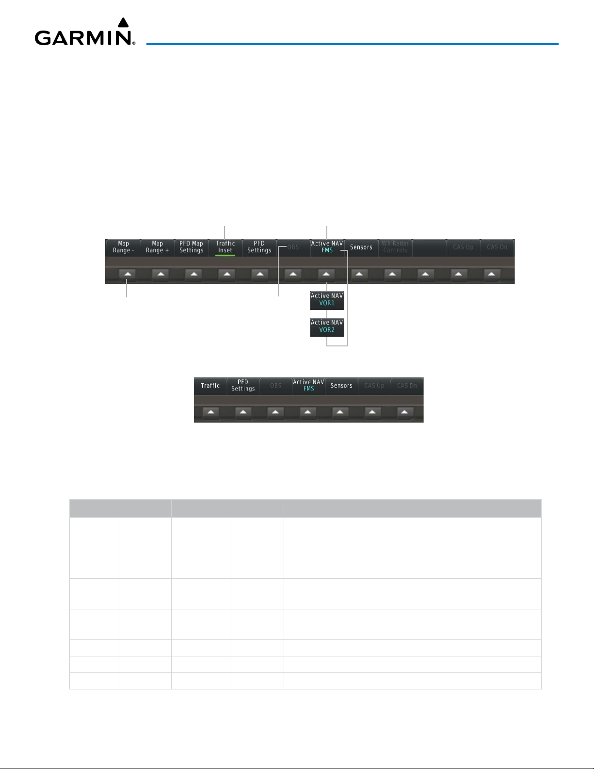
SYSTEM OVERVIEW
Selection softkeys are located along the bottom of PFD1. The softkeys shown depend on the softkey level
previously selected. The bezel keys below the softkey labels can be used to select the appropriate softkey. There
are three types of softkeys. One selects a simple on/off state, indicated by an annunciator on the softkey label
displayed as green (on) or gray (off). The next type of softkey selects among several options, indicated by the
softkey label changing (with the exception of the Map Range keys) to reflect the name of the chosen option.
The last type of softkey, when pressed displays another set of softkeys available for the selected function. Also,
these softkeys revert to the previous level after 45 seconds of inactivity. When a softkey function is disabled,
the softkey label is subdued. When the PFD is in split mode, an alternate softkey configuration is shown with
a reduced number of softkeys displayed on the left pane.
Selected
Function
On
Softkey Names
(FMS selected for
the CDI)
Bezel-Mounted
Softkeys (Press)
Subdued Softkey
(function
unavailable)
Full Mode
Split or Reversionary Mode
Figure 1-4 Top Level PFD Softkeys
Each softkey sublevel has a BACK Softkey which can be selected to return to the previous level.
Level 1 Level 2 Level 3 Level 4
Map
Description
Decreases the PFD Map display range
Range -
Map
Increases the PFD Map display range
Range +
PFD Map
Displays the PFD Map display settings softkeys
Settings
Map
Displays softkeys used to select map layouts
Layout
Map Off
Inset Map
HSI Map
Removes the PFD Map from the display
• Displays the Inset Map
• Displays the HSI Map
190-02046-02 Rev. A
Garmin G3000 Pilot’s Guide for the Daher TBM 930
5

SYSTEM OVERVIEW
Level 1 Level 2 Level 3 Level 4
Inset Traffic
HSI Traffic
Detail
Weather
Legend
Traffic
Storm-
scope
Terrain • Off: Removes terrain information from the PFD Map.
Data Link
Settings
Description
Overlays a dedicated traffic display on the Inset Map.
Overlays a dedicated traffic display on the HSI.
Selects desired amount of map detail; cycles through declutter
levels:
• All (No Declutter): All map features visible
• DCLTR 1: Declutters land data
• DCLTR 2: Declutters land and SUA data
• Least: Removes everything except for the active flight plan
Displays/removes the name of the selected data link weather
provider (SiriusXM, Connext, FIS-B) and the weather product icon
and age box (for enabled weather products).
Adds or removes the display of traffic on the PFD Map. The softkey
annunciator is green when the traffic function is on. When the
traffic function is off, the annunciator is gray.
Adds or removes the display of Stormscope information on the PFD
Map. The softkey annunciator is green when the function is on.
When the function is off, the annunciator is gray.
• Absolute: Displays Absolute terrain information on the PFD
Map.
• Relative: Displays relative terrain information on the PFD Map.
• Displays Data Link settings softkeys.
Data Link Selects the data link source for the PFD Map:
• Connext: Selects Garmin Connext (optional) as the weather
source for the display of weather data on the PFD Map.
• SiriusXM: Selects SiriusXM (optional) as the weather source for
the display of weather data on the PFD Map.
• FIS-B: Selects FIS-B (optional) as the weather source for the
display of weather data on the PFD Map.
NEXRAD Selects type of NEXRAD coverage:
• CONUS: Selects NEXRAD coverage for continental U.S.
• Regional: Selects NEXRAD coverage for a region which
provides a higher resolution.
• Combined: Combines CONUS and Regional coverages.
Source Selects USA or Canada as the source when SiriusXM is enabled as
the datalink setting.
Storm Cell
Movement
NEXRAD
Animation
Adds or removes the display of storm cell movement. Available
when SiriusXM is selected as the weather source.
Animates NEXRAD Data. Available when SiriusXM is selected as the
weather source.
Garmin G3000 Pilot’s Guide for the Daher TBM 930
190-02046-02 Rev. A6

SYSTEM OVERVIEW
Level 1 Level 2 Level 3 Level 4
WX
Overlay
SiriusXM
Lightning
Or
Description
Selects the display of weather information on the PFD Map:
• SiriusXM: Selects SiriusXM as the weather source for the
display of weather data when SiriusXM is selected as the weather
source using the Data Link softkey.
• Connext: Selects Connext as the weather source for the
display of weather data when Connext is selected as the weather
source using the Data Link softkey.
• WX Radar: Displays airborne weather radar map overlay on
the Inset or HSI Map.
• FIS-B: Selects FIS-B as the weather source for the display of
weather data when FIS-B is selected as the weather source using
the Data Link softkey.
• Off: Removes weather data from HSI Map.
Softkey is available when SiriusXM is selected as the weather source
under Data Link Settings. Adds/removes the display of SiriusXM
information on the PFD Map. The softkey annunciator is green
when the lightning function is on. When the lightning function is
off, the annunciator is gray.
Traffic
Map
PFD
Settings
Connext
Lightning
METAR
Attitude
Overlays
Pathways
Synthetic
Terrain
Horizon
Heading
Airport
Signs
Softkey is available when Connext is selected as the weather
source Data Link Settings. Adds/removes the display of Connext
information on the PFD Map. The softkey annunciator is green
when the lightning function is on. When the lightning function is
off, the annunciator is gray.
Adds or removes the display of SiriusXM, Connext, or FIS-B sourced
METAR data on the PFD Map. The softkey annunciator is green
when the METAR data is enabled. When the METAR data is off, the
annunciator is gray.
Replaces the PFD Map with a dedicated traffic display. The softkey
annunciator is green when the dedicated traffic display on. When
the PFD Map is on, the softkey annunciator is gray.
Displays the PFD settings softkeys.
Displays the softkeys for enabling or disabling Synthetic Vision
features.
Displays Pathway Boxes on the Synthetic Vision Display.
Enables synthetic terrain depiction.
Displays compass heading along the Zero-Pitch line.
Displays position markers for airports within approximately 15 nm of
the current aircraft position. Airport identifiers are displayed when
the airport is within approximately 9 nm.
190-02046-02 Rev. A
Garmin G3000 Pilot’s Guide for the Daher TBM 930
7

SYSTEM OVERVIEW
Level 1 Level 2 Level 3 Level 4
PFD Mode
Bearing 1
Bearing 2
Other PFD
Settings
Wind
Option 1
Option 2
Description
Enables or disables a multi-function Display Pane to the right or left
(depending on pilot-side or copilot-side) on the PFD.
• FULL: Display Pane is disabled. The PFD display occupies the full
screen.
• Split: Display Pane is enabled. The PFD screen is split between
the PFD display and the Display Pane.
Cycles the Bearing 1 Information Window through NAV1, NAV2,
FMS/waypoint identifier and GPS-derived distance information,
ADF1/frequency, and Off.
Cycles the Bearing 2 Information Window through NAV1, NAV2, FMS/
waypoint identifier and GPS-derived distance information, ADF1/
frequency, and Off.
Displays additional PFD settings softkeys.
Displays the wind option softkeys
Headwind/tailwind and crosswind arrows with numeric speed
components.
Total wind direction arrow with numeric speed.
OBS
Active
NAV
Sensors
ADC
Settings
AOA
Altitude
Units
COM1
121.5
ADC 1
Option 3
Off
Meters
IN
HPA
Total wind direction arrow with digital numeric direction and speed.
Information not displayed.
Selects the display mode for the Angle of Attack (AOA) indicator on
the PFD
• On: Displays AOA indicator on the PFD
• Off: Removes AOA indicator from the PFD
Displays softkeys to select altitude unit parameters.
When enabled, adds altimeter meters overlay.
Press to display the BARO setting as inches of mercury
Press to display the BARO setting as hectopascals.
Sets COM1 to 121.50 MHz.
Selects OBS mode on the CDI when navigating by FMS (only
available with active leg). When OBS is on, the softkey annunciator
is green.
Cycles through FMS, VOR1, and VOR2 navigation modes on the CDI.
Displays the sensor selection softkeys.
Displays the ADC selection softkeys.
Selects the number 1 ADC. The softkey annunciator is green when
selected.
Garmin G3000 Pilot’s Guide for the Daher TBM 930
190-02046-02 Rev. A8

SYSTEM OVERVIEW
Level 1 Level 2 Level 3 Level 4
ADC 2
AHRS
Settings
AHRS 1
AHRS 2
WX Radar
Controls
Mode
Display
Description
Selects the number 2 ADC. The softkey annunciator is green when
selected.
Displays the AHRS selection softkeys.
Selects the number 1 AHRS. The softkey annunciator is green when
selected.
Selects the number 2 AHRS. The softkey annunciator is green when
selected.
Displays the WX Radar softkeys.
Selects the display mode for the display of weather radar on the
HSI map:
• Standby: Sets the weather radar displayed on the HSI map
to Standby when airborne.
• On: Enables display of weather radar on the HSI Map.
If enabled (Mode Softkey On), selects the mode of weather radar
displayed. If not enabled, this softkey is subdued.
• Ground: Allows ground mapping returns to be displayed on
the HSI map.
•
Weather:
map.
Allows weather returns to be displayed on the HSI
Tilt Down
Tilt Up
Gain -
Gain +
GND Clutter
Suppression
Features
WX WATCH
Altitude
COMP Tilt
Turbulence
Detection
Pressing the softkey once adjusts the antenna tilt angle down in
0.25º increments. Pressing and holding the softkey continues
adjustment.
Pressing the softkey once adjusts the antenna tilt angle up in
0.25º increments. Pressing and holding the softkey continues
adjustment.
Pressing the softkey once decreases the gain in increments of 0.5.
Pressing and holding the softkey continues adjustment. A manual
setting of ‘0.0’ is equivalent to the calibrated gain setting.
Pressing the softkey once increases the gain in increments of 0.5.
Pressing and holding the softkey continues adjustment. A manual
setting of ‘0.0’ is equivalent to the calibrated gain setting. NEXRAD
(Optional) Toggles ground clutter suppression.
Displays softkeys for enabling/disabling Altitude Compensated Tilt
and Antenna Stabilization.
Toggles the Weather Attenuated Color Highlight feature.
Toggles the Altitude Compensated Tilt (ACT) feature. Used to
automatically adjust tilt as aircraft climbs or descends.
(Optional) Toggles Turbulence Detection.
190-02046-02 Rev. A
Garmin G3000 Pilot’s Guide for the Daher TBM 930
9
SYSTEM OVERVIEW
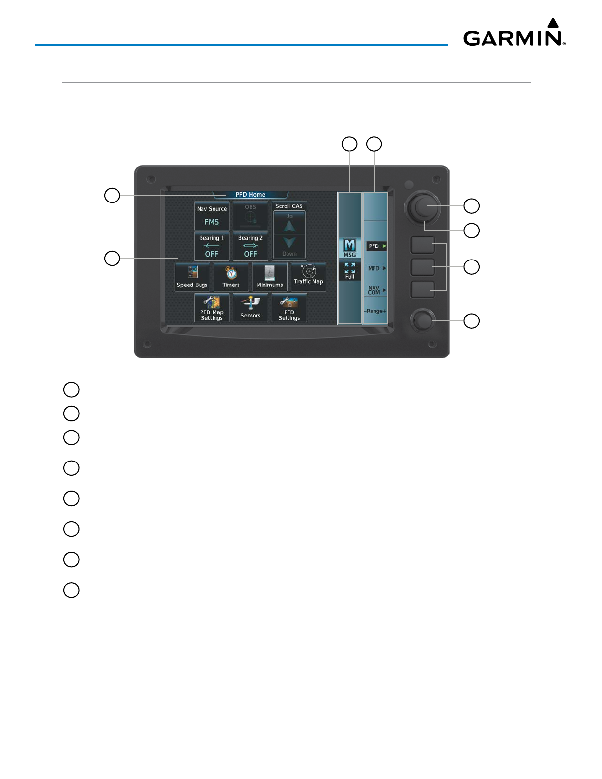
TOUCHSCREEN CONTROLLER
The two Touchscreen Controllers, designated from left to right as GTC1 and GTC2 are a pedestal-mounted
user interface allowing for ease of data entry, as well as operation of the PFD, Display Panes, and NAV/COM
system. Many procedures in this Pilot’s Guide are performed using the Touchscreen Controllers.
3 4
1
5
6
2
Figure 1-5 GTC 580 Touchscreen Controller
1
Screen Title Displays the title of the current screen
2
Screen Displays set of context sensitive controls and data
3
Button Bar Displays System level buttons (e.g. MFD Home, MSG, Full/Half/Split, Scroll Up/Down,
7
8
Back, Enter, Cancel)
4
Label Bar Displays labels to show status and current functions of knobs and softkeys, when functions
are available.
5
Small Upper Knob Provides functions as labeled on the Label Bar (e.g. Display Pane selection, COM Freq/
switching/Hold, Data Entry/map panning)
6
Large Upper Knob Provides functions as labeled on the Label Bar (e.g. Display Pane selection, COM Freq/
switching, Data Entry/map panning)
7
Softkeys Provides functions as labeled on the Label Bar (e.g. PFD/MFD/NAV Com Control Mode
selection)
8
Lower Knob Provides functions as labeled on the screen (e.g. COM volume/squelch/map range
adjustment/checklist item control)
The Touchscreen Controller uses a grid of infrared beams and sensors to detect the location of touch input,
even when the operator is wearing gloves. Objects or debris on the glass surface can interfere with these
infrared beams and cause unintended activation of buttons. A screen cleaning procedure, described later in this
section, is available to temporarily disable the touch recognition capability to facilitate screen cleaning.
In normal operations, both Touchscreen Controllers can control the PFD, MFD and NAV/COM system. The
pilot selects a control mode for a given controller (i.e. PFD, MFD, NAV/COM) by pressing context-sensitive
softkeys located on the right portion of each controller bezel. These softkeys are aligned with labels for each
control mode currently available on a given controller. A box appears around the selected control mode, and a
green arrow points to the currently selected softkey.
Garmin G3000 Pilot’s Guide for the Daher TBM 930
190-02046-02 Rev. A10

SYSTEM OVERVIEW
The Touchscreen Controller’s functions are arranged by screen. Each screen has a title which appears at the
top of the screen area. The contents of each screen change dynamically in response to the selected control
mode, and to pilot or system input. At the top level of each mode is a corresponding MFD Home containing
mode-specific controls. PFD Home is MFD Home for PFD control mode. MFD Home is MFD Home for MFD
(i.e. Display Pane) control mode. ‘NAV/COM’ Home is MFD Home for NAV/COM control mode.
The Touchscreen Controller’s available functions for the selected control mode are accessible from MFD
Home. The MFD Home may be accessed any time it is not currently displayed by touching the Home Button
in the Button Bar below the screen area. Procedures in this Pilot’s Guide generally begin from MFD Home as
a reference point; however it is not necessary to return to MFD Home before performing each procedure if the
appropriate screen is already displayed.
As the Touchscreen Controller is used, certain selections will cause another screen to be displayed. To return
to the previous screen, touch the Back or Cancel Button (as applicable) in the Button Bar, or touch the Home
Button to return to MFD Home. If MFD Home was the previous screen, pressing either the Back or Home
Button will also return to MFD Home.
The Button Bar is also where the Home, Cancel, and Back buttons are displayed. If the system issues a
message, the MSG Button is shown. Touching this button will display the ‘Messages’ Screen. The Button Bar
also contains buttons for controlling the size of MFD Display Panes (Full or Half Mode), and PFD Display Panes
(Full or Split Mode), discussed later in this section. The following buttons may be displayed on the Button Bar,
depending on current availability and/or settings.
Returns to MFD Home Selects split display mode on the PFD.
Returns to the previous screen Selects half-display mode on the MFD.
Displays the System Messages
Window on Touchscreen
Controller. Flashes when a new
system message is issued.
Displays the Telephone Window
on Touchscreen Controller.
Flashes when a new telephone
call is received.
Displays the ‘Initialization’ Screen
on Touchscreen Controller.
Button appears on MFD Home if
initialization tasks have not been
completed.
Displays the SMS Text Inbox
Window on Touchscreen
Controller. Flashes when a new
SMS message is received.
Scrolls up in a list
Scrolls down in a list
Cancels data entry and returns to the
previous screen
Accepts entered data into the system.
190-02046-02 Rev. A
Garmin G3000 Pilot’s Guide for the Daher TBM 930
11

SYSTEM OVERVIEW
Selects full-display mode when
controlling the MFD. Selects full
display mode when controlling
the PFD.
Table 1-1 Button Bar Buttons with Functions
Displays the Connext Notifications
Window on the Touchscreen Controller.
Flashes when a new Connext message
is received.
The Label Bar, on the right side of the Touchscreen Controller, displays the current function of each control
as a reference. These functions include Map Range adjustment, Display Pane selection, radio volume/squelch
adjustment, COM radio tuning, and alphanumeric data entry, which are controlled using the Touchscreen
Controller knob.
The labels change based on the context of the options being performed. If a Touchscreen Controller knob
cannot be used because of a failure in a system component (COM, NAV, Audio, etc.), the Label Bar also indicates
this status; refer to the Audio and CNS section for more information about radio failures.
The Touchscreen Controller recognizes input based on a touch, a gesture (such as sliding a finger), or by
pressing or turning the knobs or softkeys.
On-screen buttons are selected by momentarily touching them with a finger and then releasing. It is not
necessary to apply pressure, as the infrared touchscreen surface detects only the presence and movement of the
finger, not pressure. When touched, the button background is highlighted in blue until the finger is released.
If enabled, an aural ‘click’ sound is also issued to confirm the button has been touched. When releasing the
finger, make sure it released within the boundary of the button, otherwise the input is considered invalid. If
enabled, an aural ‘doink’ is heard to indicate the touch input was not accepted.
Some adjustments are made using horizontal or vertical sliders. To use, simply touch within the slider box
and slide the finger in the desired slider bar direction, then release the finger. The finger may move outside
of the slider box during adjustment; slider movement stops when either the finger is released or the slider
has reached its maximum travel. In some cases, the slider can also be adjusted by touching a + or - Button if
it accompanies the slider, such as in the Map Detail Adjustment Slider. In addition, a slider adjustment may
also be accomplished using knobs on the Touchscreen Controller if the Label Bar indicates the selected slider
supports this additional control.
Volume Adjustment Slider
Figure 1-6 Sliders on the Touchscreen Controller
Map Detail Adjustment Slider
Garmin G3000 Pilot’s Guide for the Daher TBM 930
190-02046-02 Rev. A12
SYSTEM OVERVIEW
When a Touchscreen Controller screen window contains more information than the window can currently
show, a scroll bar and scroll buttons appear. To scroll inside of a window, touch the controller while moving
the finger up or down accordingly or touch and drag the finger up or down. To scroll more quickly, move the
finger up or down rapidly in a flicking motion. Scrolling can also be performed by pressing the Up or Down
scroll buttons, each touch of the scroll button will display one ‘page’ of information. Press and hold the Up or
Down scroll buttons for a continuous scroll.
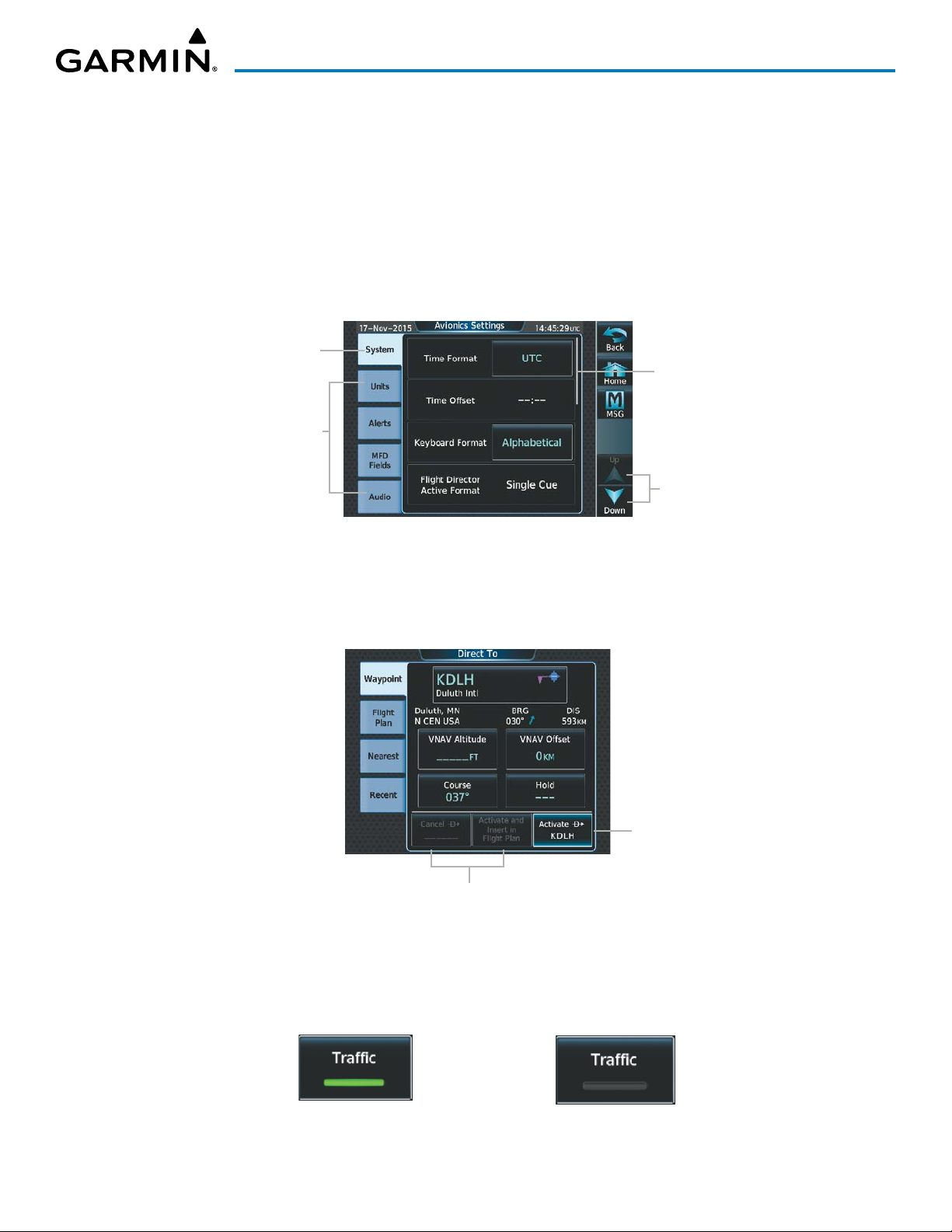
Some screens provide tabs as a means to group multiple categories of information or buttons. Touch the
desired tab to display its contents and manage settings or information. The selected tab is highlighted.
Selected Tab Highlighted
Scroll Bar
Other Available Tabs
Scroll Arrows
Figure 1-7 Touchscreen Controller with Tabs and Scroll Arrows
Elements on the Touchscreen Controller screens (such as buttons and sliders) may appear subdued to indicate
their functions are currently not available. Generally, pilot-selectable fields appear in cyan. In some cases, the
system may highlight the expected button in cyan which completes a data entry process or function.
Touch the
highlighted button
to activate the
Direct-To function
Buttons subdued until Direct-To is activated
Figure 1-8 Subdued Buttons on Touchscreen Controller
BUTTON TYPES
Annunciator Buttons operate in an on/off state. An ‘on’ or enabled button displays a green annunciator; an
‘off’ or disabled button displays a gray annunciator. Touch the annunciator button to change its state.
190-02046-02 Rev. A
On or Enabled Off or Disabled
Figure 1-9 Touchscreen Controller Annunciator Buttons
Garmin G3000 Pilot’s Guide for the Daher TBM 930
13

SYSTEM OVERVIEW
Datafield Buttons can be modified based on information the pilot can enter or change, and often contain
cyan alphanumeric text. Touching datafield buttons will either display a pop-up window from which a
selection can be made, or display a keypad to supply the data. See the Data Entry discussion in this section
for more information.
Selected
Datafield
Button
Datafield
Buttons
Figure 1-10 Touchscreen Controller Datafield Buttons
Options for
Selected
Datafield
Button
If a system failure causes a button’s function to be inaccessible, an amber ‘X’ appears over the button. These
buttons will not respond if touched.
SCREEN OVERVIEW
The following is a brief overview of the major screens used to access Touchscreen Controller functions.
Additional specific screens used to perform functions are shown and discussed in detail throughout this Pilot’s
Guide.
NOTE: Screen appearance varies based on the installed options.
MFD HoMe
Shows ‘Navigation Map’ Pane in the selected display Pane. Touch the button again to access the ‘Map Settings’
Screen on the Touchscreen Controller.
Garmin G3000 Pilot’s Guide for the Daher TBM 930
190-02046-02 Rev. A14
 Loading...