


 Loading...
G1000 IntegratedPilot’s Guide Flight Deck
Quest Kodiak 100

Copyright © 2007 Garmin Ltd. or its subsidiaries. All rights reserved.
This manual reflects the operation of System Software version 552.00 or later for the Quest Kodiak 100. Some differences in operation may be observed when comparing the information in this manual to earlier or later software versions.
Garmin International, Inc., 1200 East 151st Street, Olathe, Kansas 66062, U.S.A.
Tel: 913/397.8200 |
Fax: 913/397.8282 |
Garmin AT, Inc., 2345 Turner Road SE, Salem, OR 97302, U.S.A. |
|
Tel: 503/391.3411 |
Fax: 503/364.2138 |
Garmin (Europe) Ltd., Liberty House, Bulls Copse Road, Hounsdown Business Park, Southampton, SO40 9RB U.K. |
|
Tel: 44/0870.8501241 |
Fax: 44/0870.8501251 |
Garmin Corporation, No. 68, Jangshu 2nd Road, Shijr,Taipei County,Taiwan |
|
Tel: 886/02.2642.9199 |
Fax: 886/02.2642.9099 |
Website Address: www.garmin.com
Except as expressly provided herein, no part of this manual may be reproduced, copied, transmitted, disseminated, downloaded or stored in any storage medium, for any purpose without the express written permission of Garmin. Garmin hereby grants permission to download a single copy of this manual and of any revision to this manual onto a hard drive or other electronic storage medium to be viewed for personal use,provided that such electronic or printed copy of this manual or revision must contain the complete text of this copyright notice and provided further that any unauthorized commercial distribution of this manual or any revision hereto is strictly prohibited.
Garmin® is a registered trademark of Garmin Ltd. or its subsidiaries, and G1000® is a trademark of Garmin Ltd. or its subsidiaries. These trademarks may not be used without the express permission of Garmin.
Bendix/King® and Honeywell® are registered trademarks of Honeywell International, Inc.; NavData® is a registered trademark of Jeppesen, Inc.;Stormscope® is a registered trademark of L-3 Communications;Avidyne® andTCAD®are registered trademarks ofAvidyne Corporation; and XM® is a registered trademark of XM Satellite Radio, Inc.
June 2007 |
Printed in the U.S.A |
Garmin G1000 Pilot’s Guide for the Quest Kodiak 100 |
190-00590-00 Rev. C |

LIMITED WARRANTY
LIMITED WARRANTY
This Garmin product is warranted to be free from defects in materials or workmanship for two years from the date of purchase. Within this period, Garmin will, at its sole option, repair or replace any components that fail in normal use. Such repairs or replacement will be made at no charge to the customer for parts and labor,provided that the customer shall be responsible for any transportation cost. This warranty does not cover failures due to abuse, misuse, accident, or unauthorized alterations or repairs.
THE WARRANTIES AND REMEDIES CONTAINED HEREIN ARE EXCLUSIVE AND IN LIEU OF ALL OTHER WARRANTIES EXPRESS OR IMPLIED OR STATUTORY, INCLUDING ANY LIABILITY ARISING UNDER ANY WARRANTY OF MERCHANTABILITY OR FITNESS FOR A PARTICULAR PURPOSE, STATUTORY OR OTHERWISE. THIS WARRANTY GIVES YOU SPECIFIC LEGAL RIGHTS, WHICH MAY VARY FROM STATE TO STATE.
IN NO EVENT SHALL GARMIN BE LIABLE FOR ANY INCIDENTAL, SPECIAL, INDIRECT OR CONSEQUENTIAL DAMAGES, WHETHER RESULTING FROM THE USE, MISUSE, OR INABILITY TO USE THIS PRODUCT OR FROM DEFECTS IN THE PRODUCT. Some states do not allow the exclusion of incidental or consequential damages, so the above limitations may not apply to you.
Garmin retains the exclusive right to repair or replace the unit or software, or to offer a full refund of the purchase price, at its sole discretion. SUCH REMEDY SHALL BE YOUR SOLE AND EXCLUSIVE REMEDY FOR ANY BREACH OF WARRANTY.
To obtain warranty service, contact your local GarminAuthorized Service Center. For assistance in locating a Service Center near you, visit the Garmin Web site at “http://www.garmin.com” or contact Garmin Customer Service at 800-800-1020.
190-00590-00 Rev. C |
Garmin G1000 Pilot’s Guide for the Quest Kodiak 100 |
i |

WARNINGS, CAUTIONS, AND NOTES
WARNING: Navigation and terrain separation must NOT be predicated upon the use of the terrain function. The G1000Terrain Proximity feature is NOT intended to be used as a primary reference for terrain avoidance and does not relieve the pilot from the responsibility of being aware of surroundings during flight. The Terrain Proximity feature is only to be used as an aid for terrain avoidance and is not certified for use in applications requiring a certified terrain awareness system. Terrain data is obtained from third party sources. Garmin is not able to independently verify the accuracy of the terrain data.
WARNING: The displayed minimum safe altitudes (MSAs) are only advisory in nature and should not be relied upon as the sole source of obstacle and terrain avoidance information. Always refer to current aeronautical charts for appropriate minimum clearance altitudes.
WARNING: The Garmin G1000,as installed in Quest Kodiak 100 aircraft,has a very high degree of functional integrity. However, the pilot must recognize that providing monitoring and/or self-test capability for all conceivable system failures is not practical. Although unlikely, it may be possible for erroneous operation to occur without a fault indication shown by the G1000. It is thus the responsibility of the pilot to detect such an occurrence by means of cross-checking with all redundant or correlated information available in the cockpit.
 WARNING: For safety reasons, G1000 operational procedures must be learned on the ground.
WARNING: The altitude calculated by G1000 GPS receivers is geometric height above Mean Sea Level and could vary significantly from the altitude displayed by pressure altimeters, such as the GDC 74A Air Data Computer, or other altimeters in aircraft. GPS altitude should never be used for vertical navigation. Always use pressure altitude displayed by the G1000 PFD or other pressure altimeters in aircraft.
WARNING:Donotuseoutdateddatabaseinformation.DatabasesusedintheG1000systemmustbeupdated regularly in order to ensure that the information remains current. Pilots using any outdated database do so entirely at their own risk.
WARNING: Do not use basemap (land and water data) information for primary navigation. Basemap data is intended only to supplement other approved navigation data sources and should be considered as an aid to enhance situational awareness.
WARNING: Traffic information shown on the G1000 Multi Function Display is provided as an aid in visually acquiring traffic. Pilots must maneuver the aircraft based only upon ATC guidance or positive visual acquisition of conflicting traffic.
WARNING: XM Weather should not be used for hazardous weather penetration. Weather information provided by the GDL 69 is approved only for weather avoidance, not penetration.
WARNING: NEXRAD weather data is to be used for long-range planning purposes only. Due to inherent delays in data transmission and the relative age of the data, NEXRAD weather data should not be used for short-range weather avoidance.
ii |
Garmin G1000 Pilot’s Guide for the Quest Kodiak 100 |
190-00590-00 Rev. C |
WARNINGS, CAUTIONS, AND NOTES
WARNING: The United States government operates the Global Positioning System and is solely responsible for its accuracy and maintenance. The GPS system is subject to changes which could affect the accuracy and performance of all GPS equipment. Portions of the Garmin G1000 utilize GPS as a precision electronic NAVigation AID (NAVAID). Therefore, as with all NAVAIDs, information presented by the G1000 can be misused or misinterpreted and, therefore, become unsafe.
WARNING: To reduce the risk of unsafe operation, carefully review and understand all aspects of the G1000 Pilot’s Guide documentation and the Quest Kodiak 100 Aircraft Flight Manual. Thoroughly practice basic operation prior to actual use. During flight operations, carefully compare indications from the G1000 to all available navigation sources,including the information from other NAVAIDs,visual sightings,charts,etc. For safety purposes, always resolve any discrepancies before continuing navigation.
WARNING: The illustrations in this guide are only examples. Never use the G1000 to attempt to penetrate a thunderstorm. Both the FAA Advisory Circular, Subject: Thunderstorms, and the Airman’s Information Manual (AIM) recommend avoiding“by at least 20 miles any thunderstorm identified as severe or giving an intense radar echo.”
CAUTION: The Garmin G1000 does not contain any user-serviceable parts. Repairs should only be made by an authorized Garmin service center. Unauthorized repairs or modifications could void both the warranty and the pilot’s authority to operate this device under FAA/FCC regulations.
CAUTION: The PFD and MFD use a lens coated with a special anti-reflective coating that is very sensitive to skin oils, waxes, and abrasive cleaners. CLEANERS CONTAINING AMMONIA WILL HARM THE ANTIREFLECTIVE COATING. It is very important to clean the lens using a clean, lint-free cloth and an eyeglass lens cleaner that is specified as safe for anti-reflective coatings.
NOTE: Interference from GPS repeaters operating inside nearby hangers can cause the intermittent loss of attitude and heading displays while the aircraft is on the ground. Moving the aircraft more than 100 feet from the source of the interference should remedy the condition.
NOTE:Thisdevicecomplieswithpart15oftheFCCRules. Operationissubjecttothefollowingtwoconditions:
(1) this device may not cause harmful interference,and (2) this device must accept any interference received, including interference that may cause undesired operation.
NOTE: There are several atmospheric phenomena in addition to nearby thunderstorms that can cause isolated discharge points in the strike display mode. However, clusters of two or more discharge points in the strike display mode do indicate thunderstorm activity if these points reappear after the screen has been cleared. Avoid the clusters to avoid the thunderstorms. In the cell display mode, even a single discharge point may represent thunderstorm activity and should therefore be avoided.
 NOTE: This product, its packaging, and its components contain chemicals known to the State of California to cause cancer, birth defects, or reproductive harm. This notice is being provided in accordance with California’s Proposition 65. If you have any questions or would like additional information, please refer to our web site at www.garmin.com/prop65.
190-00590-00 Rev. C |
Garmin G1000 Pilot’s Guide for the Quest Kodiak 100 |
iii |

REVISION INFORMATION
Record of Revision
Part Number |
Revision |
Date |
Page Range |
Description |
190-00590-00 |
1 |
3/13/06 |
All |
Initial release |
190-00590-00 |
A |
3/21/07 |
All |
Production Release |
190-00590-00 |
B |
4/3/07 |
All |
Added Print Specification Reference to Cover Sheet |
190-00590-00 |
C |
6/22/07 |
All |
Revised AMPS Engine Gauge |
|
|
|
|
|
iv |
Garmin G1000 Pilot’s Guide for the Quest Kodiak 100 |
190-00590-00 Rev. C |

TABLE OF CONTENTS
|
SECTION 1 SYSTEM OVERVIEW |
|
|
|
SECTION 3 ENGINE INDICATION SYSTEM (EIS) |
|
1.1 |
System Description.............................................. |
1-1 |
3.1 |
Engine Display...................................................... |
3-2 |
|
1.2 |
Line Replaceable Units........................................ |
1-2 |
3.2 |
System Display ..................................................... |
3-4 |
|
1.3 Secure Digital (SD) Cards.................................... |
1-5 |
3.3 |
Fuel Display........................................................... |
3-6 |
||
1.4 |
System Power-Up |
1-6 |
|
|
|
|
|
|
SECTION 4 AUDIO PANEL AND CNS |
|
|||
1.5 |
.................................................System Operation |
1-7 |
4.1 |
Overview |
4-1 |
|
|
Normal Display Operation |
1-7 |
||||
|
|
|
PFD/MFD Controls and Frequency Display |
4-2 |
||
|
Reversionary Display Operation |
1-9 |
|
|
||
|
|
|
Audio Panel Controls |
4-4 |
||
|
AHRS Operation |
1-10 |
|
|
||
|
4.2 |
COM Operation |
4-6 |
|||
|
G1000 SystemAnnunciations |
1-11 |
||||
|
|
|
COMTransceiver Selection andActivation |
4-6 |
||
1.6 |
G1000 Controls |
1-12 |
|
|
||
|
|
COMTransceiver ManualTuning |
4-7 |
|||
|
PFD/MFD Controls |
1-12 |
|
|
||
|
|
|
Quick-Tuning andActivating 121.500 MHz |
4-8 |
||
|
Softkey Function |
1-13 |
|
|
||
|
|
|
Auto-Tuning the COM Frequency |
4-9 |
||
1.7 |
Accessing G1000 Functionality |
1-18 |
|
|
||
|
|
Frequency Spacing |
4-13 |
|||
|
Menus |
1-18 |
|
|
||
|
|
|
Automatic Squelch................................................... |
4-14 |
||
|
Data Entry .............................................................. |
1-18 |
|
|
Volume................................................................... |
4-14 |
|
Page Groups ........................................................... |
1-19 |
4.3 |
NAV Operation.................................................... |
4-15 |
|
|
System Setup and Status.......................................... |
1-22 |
|
|
NAV Radio Selection andActivation |
4-15 |
1.8 |
Display Backlighting |
1-32 |
|
|
||
|
|
NAV Receiver ManualTuning |
4-16 |
|||
|
|
|
|
|
||
|
|
|
|
|
Auto-Tuning the NAV Frequency |
4-18 |
|
SECTION 2 FLIGHT INSTRUMENTS |
|
|
|
||
2.1 |
Flight Instruments |
2-4 |
|
|
...........................................Marker Beacon Receiver |
4-23 |
|
4.4 GTX 33 Mode S Transponder |
4-24 |
||||
|
Airspeed Indicator |
2-4 |
|
|||
|
|
|
Transponder Controls |
4-24 |
||
|
Attitude Indicator |
2-6 |
|
|
||
|
|
|
Transponder Mode Selection |
4-25 |
||
|
Altimeter |
2-7 |
|
|
||
|
|
|
Entering aTransponder Code |
4-27 |
||
|
Vertical Deviation/Glideslope Indicator |
2-8 |
|
|
||
|
|
|
IDENT Function |
4-29 |
||
|
Vertical Speed Indicator (VSI) |
2-8 |
|
|
||
|
|
|
Flight ID Reporting |
4-30 |
||
|
Horizontal Situation Indicator (HSI) |
2-9 |
|
|
||
|
4.5 |
Additional Audio Panel Functions |
4-31 |
|||
|
Course Deviation Indicator ....................................... |
2-12 |
||||
2.2 |
Supplemental Flight Data................................. |
2-17 |
|
|
Power-up................................................................ |
4-31 |
|
GenericTimer |
2-17 |
|
|
Mono/Stereo Headsets............................................. |
4-31 |
|
|
|
Speaker |
4-31 |
||
|
SystemTime |
2-18 |
|
|
||
|
|
|
Intercom |
4-32 |
||
|
OutsideAirTemperature |
2-19 |
|
|
||
|
|
|
PassengerAddress (PA) System |
4-34 |
||
2.3 |
PFD Annunciations and Alerting Functions |
2-20 |
|
|
||
|
|
Clearance Recorder and Player |
4-34 |
|||
|
G1000Alerting System |
2-20 |
|
|
||
|
|
|
Entertainment Inputs |
4-35 |
||
|
TrafficAnnunciation |
2-21 |
|
|
||
|
|
|
Simultaneous COM Operation |
4-36 |
||
|
TAWSAnnunciations |
2-21 |
|
|
||
|
|
4.6 Audio Panels Preflight Procedure |
4-37 |
|||
|
Marker BeaconAnnunciations |
2-22 |
|
|||
|
|
|
|
|
||
|
AltitudeAlerting...................................................... |
2-22 |
|
|
|
|
|
Barometric Minimum DescentAltitude....................... |
2-23 |
|
|
|
|
190-00590-00 Rev. C |
Garmin G1000 Pilot’s Guide for the Quest Kodiak 100 |
v |

TABLE OF CONTENTS
4.7 |
Abnormal Operation.......................................... |
4-39 |
|
Stuck Microphone.................................................... |
4-39 |
|
COMTuning Failure.................................................. |
4-39 |
|
Audio Panel Fail-Safe Operation................................ |
4-39 |
|
Reversionary Mode.................................................. |
4-40 |
|
|
|
|
SECTION 5 GPS NAVIGATION |
|
5.1 |
Navigation Map (MFD)........................................ |
5-2 |
|
Navigation Map Page Setup and Operation.................. |
5-2 |
5.2 |
PFD Inset Map and Windows............................ |
5-24 |
|
Inset Map............................................................... |
5-24 |
|
PFDWindows.......................................................... |
5-25 |
5.3 |
Direct-to-Navigation (MFD) ............................. |
5-27 |
|
Direct-to Navigation Shortcuts from the MFD............. |
5-31 |
5.4 |
Direct-to-Navigation (PFD) .............................. |
5-32 |
5.5 |
Airport Information ........................................... |
5-35 |
5.6 |
Intersection Information................................... |
5-41 |
5.7 |
NDB Information................................................ |
5-43 |
5.8 |
VOR Information................................................. |
5-45 |
5.9 |
User Waypoint Information............................... |
5-47 |
5.10 |
Nearest Airports................................................. |
5-53 |
5.11 |
Nearest Airports (PFD)....................................... |
5-56 |
5.12 |
Nearest Intersections......................................... |
5-58 |
5.13 |
Nearest NDB ....................................................... |
5-59 |
5.14 |
Nearest VOR........................................................ |
5-60 |
5.15 |
Nearest Frequencies .......................................... |
5-63 |
5.16 |
Nearest Airspaces............................................... |
5-66 |
5.17 |
Nearest User Waypoint...................................... |
5-70 |
5.18 |
Flight Planning ................................................. |
5-72 |
|
Flight Planning from the MFD................................... |
5-72 |
|
Vertical Navigation.................................................. |
5-94 |
|
Flight Planning from the PFD ................................... |
5-97 |
5.19 |
Procedures ........................................................ |
5-101 |
|
Departures,Arrivals, andApproaches (MFD)............. |
5-101 |
|
Departures,Arrivals, andApproaches (PFD).............. |
5-112 |
|
|
|
|
SECTION 6 HAZARD AVOIDANCE |
|
6.1 |
XM Satellite Weather........................................... |
6-1 |
|
Activating Services..................................................... |
6-1 |
|
Using XM SatelliteWeather Products........................... |
6-3 |
|
Weather Softkeys....................................................... |
6-5 |
Setting Up theWeather Data Link Page ..................... |
6-24 |
Setting Up XM SatelliteWeather on the Navigation Map.... |
|
6-27 |
|
6.2 TAWS ...................................................................... |
6-29 |
Requirements.......................................................... |
6-29 |
Computing GPSAltitude forTAWS............................. |
6-29 |
UsingTAWS ............................................................ |
6-30 |
TAWS Symbols ........................................................ |
6-34 |
TAWSAlerts............................................................ |
6-34 |
6.3 Traffic Information Service (TIS).......................... |
6-41 |
TIS Symbology......................................................... |
6-41 |
DisplayingTraffic Data ............................................. |
6-42 |
Traffic Map Page...................................................... |
6-43 |
Navigation Map Page............................................... |
6-47 |
6.4 L-3 SKYWATCH Traffic Advisory System (SKY497) |
|
(Optional)...................................................................... |
6-50 |
User-initiated test.................................................... |
6-50 |
SKYWATCHTAS Symbology...................................... |
6-51 |
|
|
SECTION 7 AUTOMATIC FLIGHT CONTROL SYSTEM |
|
|
|
SECTION 8 ADDITIONAL FEATURES |
|
8.1 XM Digital Audio Entertainment (Optional) ..... |
8-1 |
XM Satellite Radio Service.......................................... |
8-1 |
XM ServiceActivation................................................ |
8-2 |
Using XM Radio ........................................................ |
8-3 |
8.2 Abnormal Operation............................................ |
8-7 |
|
|
APPENDICES |
|
Annunciations and Alerts.............................................. |
A-1 |
Alert Level Definitions................................................ |
A-2 |
AircraftAlerts............................................................ |
A-2 |
G1000 SystemAnnunciations ..................................... |
A-4 |
G1000 System MessageAdvisories.............................. |
A-7 |
TAWSALERTS.......................................................... |
A-18 |
TAWS System StatusAnnunciations........................... |
A-18 |
SD Card Use.................................................................... |
B-1 |
Jeppesen Databases................................................... |
B-1 |
Garmin Databases..................................................... |
B-2 |
Glossary........................................................................... |
C-1 |
Frequently Asked Questions......................................... |
D-1 |
vi |
Garmin G1000 Pilot’s Guide for the Quest Kodiak 100 |
190-00590-00 Rev. C |

TABLE OF CONTENTS
General TIS Information |
................................................E-1 |
Introduction.............................................................. |
E-1 |
TIS vs.TAS/TCAS........................................................ |
E-1 |
TIS Limitations .......................................................... |
E-1 |
Map Symbols.................................................................. |
F-1 |
|
|
|
INDEX |
Index ................................................................................ |
I-1 |
190-00590-00 Rev. C |
Garmin G1000 Pilot’s Guide for the Quest Kodiak 100 |
vii |

TABLE OF CONTENTS
BLANK PAGE
viii |
Garmin G1000 Pilot’s Guide for the Quest Kodiak 100 |
190-00590-00 Rev. C |
SYSTEM OVERVIEW
SECTION 1 SYSTEM OVERVIEW
1.1 SYSTEM DESCRIPTION
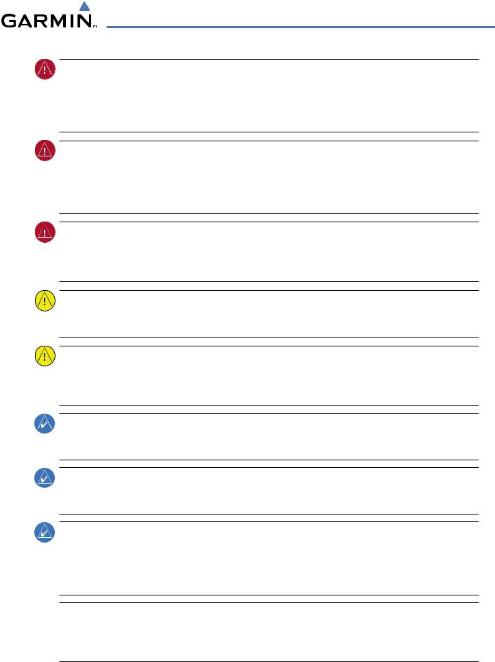
This section is designed to provide an overview of the G1000 Integrated Flight Deck installed in the Quest Kodiak 100. The G1000 is an integrated flight deck system that presents flight instrumentation, position, navigation, communication, and identification information to the pilot using flat-panel color displays. The system is distributed across the following Line Replaceable Units (LRUs):
•GDU 1040 Primary Flight Display (PFD)/Multi Function Display (MFD)
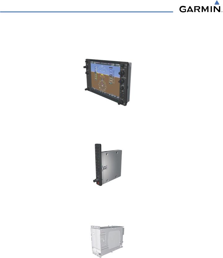
•GMA 1347 Audio Panel with Integrated Marker Beacon Receiver
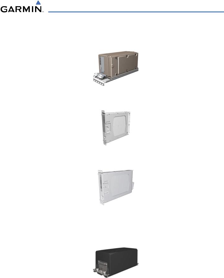
•GIA 63 Integrated Avionics Units (IAU)
•GDC 74A Air Data Computer (ADC)
•GEA 71 Engine/Airframe Unit
•GTX 33 Mode S Transponder
•GRS 77 Attitude and Heading Reference System (AHRS)
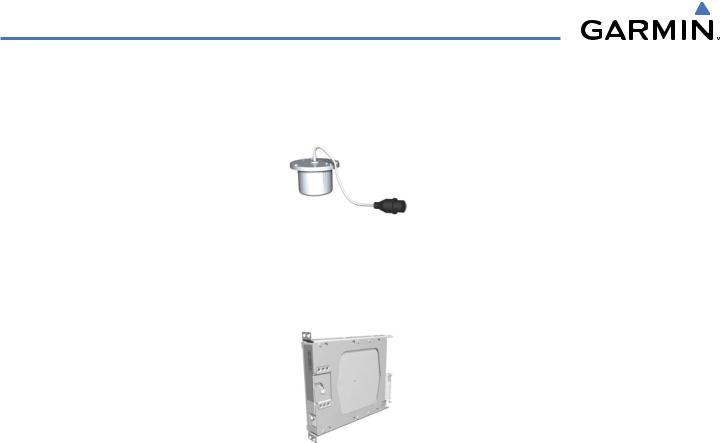
•GMU 44 Magnetometer
•GDL 69A Data Link Receiver
190-00590-00 Rev. C |
Garmin G1000 Pilot’s Guide for the Quest Kodiak 100 |
1-1 |
SYSTEM OVERVIEW
1.2 LINE REPLACEABLE UNITS
•GDU 1040 (3) – The GDU 1040 is configured as two Primary Flight Displays (PFD) and one Multi Function Display (MFD). The displays communicate with each other through a High-Speed Data Bus (HSDB) Ethernet connection. Each display is also paired with an Ethernet connection to an IAU.
•GMA 1347 – The Audio Panel integrates navigation/communication radio (NAV/COM) digital audio, intercom, and marker beacon controls, and is installed between the displays. This unit also provides manual control of displayreversionarymode(redDISPLAYBACKUPbutton;seeSection1.5,SystemOperation)andcommunicates with both IAUs using an RS-232 digital interface.
•GIA 63 (2) – The Integrated Avionics Units (IAU) function as the main communications hub, linking all LRUs with the PFD. Each IAU contains VHF COM/NAV/GS receivers and system integration microprocessors and is paired with the on-side display via a HSDB connection. The IAUs are not paired together and do not communicate with each other directly.
1-2 |
Garmin G1000 Pilot’s Guide for the Quest Kodiak 100 |
190-00590-00 Rev. C |
SYSTEM OVERVIEW
•GDC74 – The Air Data Computer (ADC) processes data from the pitot/static system and outside air temperature (OAT) sensor. The ADC provides pressure altitude, airspeed, vertical speed, and OAT information to the G1000 System, and it communicates with the primary IAU, displays, and AHRS using an ARINC 429 digital interface.
•GEA 71 – The Engine Airframe Unit receives and processes signals from the engine and airframe sensors. This unit communicates with both IAUs using an RS-485 digital interface.
•GTX 33 – The solid-state Transponder provides Modes A, C, and S capability and communicates with both IAUs through an RS-232 digital interface.
•GRS 77 (2) – The Attitude and Heading Reference System (AHRS) provides aircraft attitude and heading information via ARINC 429 to both the PFD and the primary IAU. The AHRS contains advanced sensors (including accelerometers and rate sensors) and interfaces with the Magnetometer to obtain magnetic field information, with the ADC to obtain air data, and with both IAUs to obtain GPS information. AHRS operation is discussed in Section 1.5, System Operation.
190-00590-00 Rev. C |
Garmin G1000 Pilot’s Guide for the Quest Kodiak 100 |
1-3 |
SYSTEM OVERVIEW
•GMU 44 – The Magnetometer measures local magnetic field and sends data to the AHRS for processing to determine aircraft magnetic heading. This unit receives power directly from the AHRS and communicates with it via an RS-485 digital interface.
•GDL 69A – The Data Link Satellite Radio Receiver provides real-time weather information to the G1000 MFD and PFD Inset Map, as well as digital audio entertainment. The Data Link Receiver communicates with the MFD via a HSDB connection. A subscription to XM Satellite Radio Service is required to enable the GDL 69A capability.
1-4 |
Garmin G1000 Pilot’s Guide for the Quest Kodiak 100 |
190-00590-00 Rev. C |
SYSTEM OVERVIEW
1.3 SECURE DIGITAL (SD) CARDS
 NOTE: Ensure the G1000 System is powered off before inserting an SD card.
 NOTE: Refer to Appendix B for instructions on updating the aviation database.
The PFD and MFD data card slots use Secure Digital (SD) cards and are located on the upper right side of the display bezels. Each display bezel is equipped with two SD card slots. SD cards are used for aviation database and system software updates as well as terrain database storage.
Installing an SD card:
1)Insert the SD card in the SD card slot (the front of the card should be flush with the face of the display bezel).
2)To eject the card, gently press on the SD card to release the spring latch.
SD Card Slots
Figure 1-1 Display Bezel SD Card Slots
190-00590-00 Rev. C |
Garmin G1000 Pilot’s Guide for the Quest Kodiak 100 |
1-5 |

SYSTEM OVERVIEW
1.4 SYSTEM POWER-UP
 NOTE: See the Aircraft Flight Manual (AFM) for specific procedures concerning avionics power application and emergency power supply operation.
 NOTE: Refer to Appendix A for system-specific annunciations and alerts.
The G1000 System is integrated with the aircraft electrical system and receives power directly from electrical busses. The G1000 PFD, MFD, and supporting sub-systems include both power-on and continuous built-in test features that exercise the processor, RAM, ROM, external inputs, and outputs to provide safe operation.
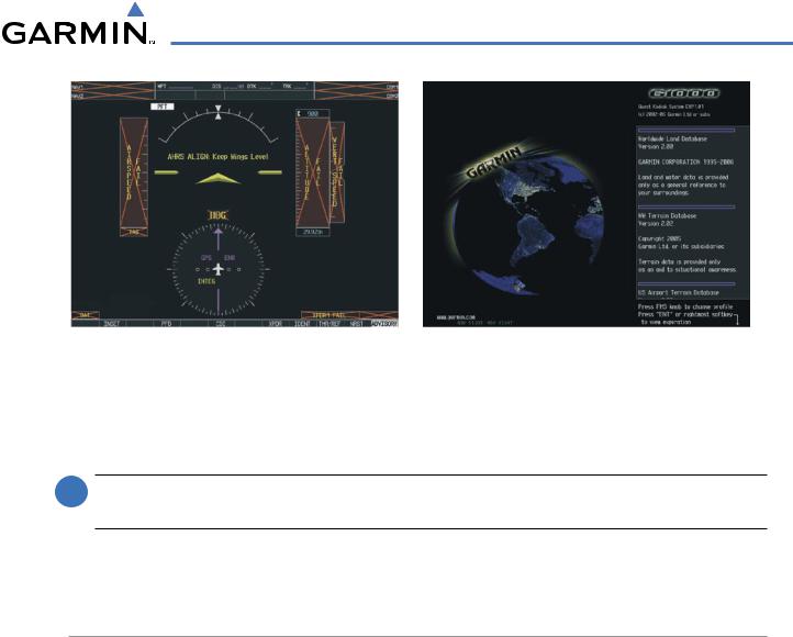
During system initialization, test annunciations are displayed, as shown in Figure 1-2. All system annunciations should disappear typically within the first minute of power-up. Upon power-up, key annunciator lights also become momentarily illuminated on the Audio Panel, the MFD/PFD Control Unit, and the display bezels.
On the PFD, the AHRS begins to initialize and displays “AHRS ALIGN: Keep Wings Level”. The AHRS should display valid attitude and heading fields typically within the first minute of power-up. The AHRS can align itself both while taxiing and during level flight.
When the MFD powers up, the splash screen (Figure 1-5) displays the following information:
• System version |
• Obstacle database name and version |
• Copyright |
• Terrain database name and version |
• Land database name and version |
• Aviation database name, version, and effective dates |
Current database information includes valid operating dates, cycle number, and database type. When this information has been reviewed for currency (to ensure that no databases have expired), the pilot is prompted to continue.
Pressing the ENT Key (or right-most softkey) acknowledges this information, and the Navigation Map Page is displayed upon pressing the key a second time. When the system has acquired a sufficient number of satellites to determine a position, the aircraft’s current position is shown on the Navigation Map Page.
1-6 |
Garmin G1000 Pilot’s Guide for the Quest Kodiak 100 |
190-00590-00 Rev. C |
SYSTEM OVERVIEW
Figure 1-2 PFD Initialization |
Figure 1-3 MFD Power-Up Splash Screen |
1.5 SYSTEM OPERATION
 NOTE: In normal operating mode, backlighting can only be adjusted from the PFD. In reversionary mode, it can be adjusted from the remaining display.
The displays are connected together via a single Ethernet bus for high-speed communication. Each IAU is connected to the on-side display. This section discusses normal and reversionary G1000 display operation, as well as the various AHRS modes and G1000 System Annunciations.
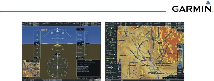
NORMAL DISPLAY OPERATION
In normal operating mode, the PFD presents graphical flight instrumentation (attitude, heading, airspeed, altitude, vertical speed), replacing the traditional flight instrument cluster (see the Flight Instruments Section for more information).
The MFD normally displays a full-color moving map with navigation information (see the GPS Navigation Section), while the left portion of the MFD is dedicated to the Engine Indication System (EIS; see the EIS Section).
Both displays offer control for COM and NAV frequency selection.
190-00590-00 Rev. C |
Garmin G1000 Pilot’s Guide for the Quest Kodiak 100 |
1-7 |
SYSTEM OVERVIEW
Primary Flight Display |
Multi Function Display |
Figure 1-4 G1000 Normal Display Operation
1-8 |
Garmin G1000 Pilot’s Guide for the Quest Kodiak 100 |
190-00590-00 Rev. C |
SYSTEM OVERVIEW
REVERSIONARY DISPLAY OPERATION
 NOTE: The G1000 System alerts the pilot when backup paths are utilized by the LRUs. Refer to Appendix A for further information regarding system-specific alerts.
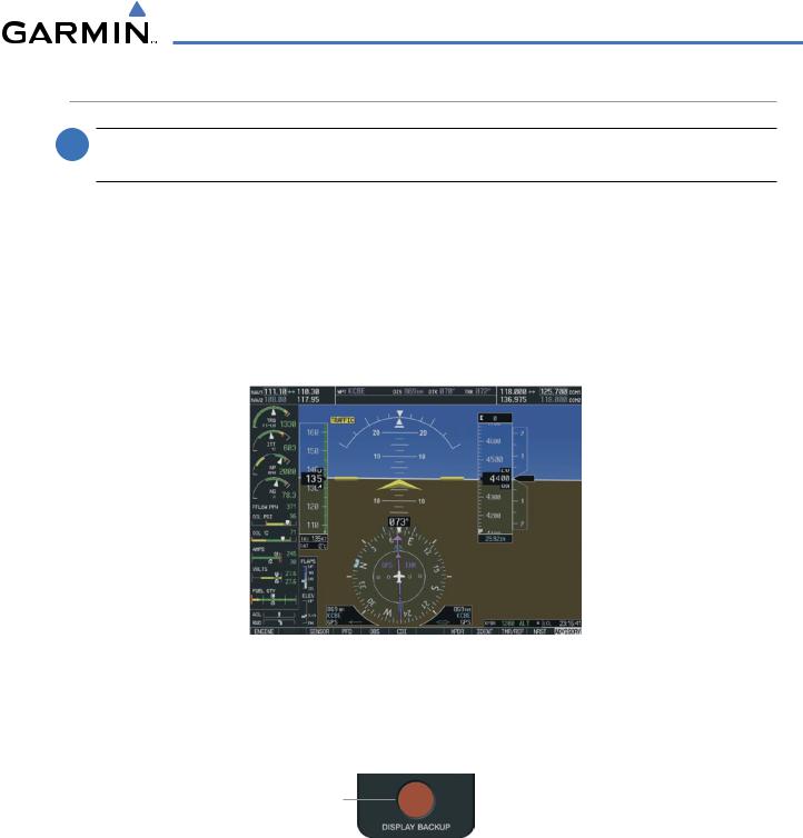
In the event of a display failure, the G1000 System automatically switches to reversionary (backup) mode. In reversionary mode, all important flight information is presented on the remaining display in the same format as in normal operating mode.
If a display fails, the appropriate IAU-display Ethernet interface is cut off. Thus, the IAU can no longer communicate with the remaining display, and the NAV and COM functions provided to the failed display by the IAU are flagged as invalid on the remaining display. The system reverts to backup paths for the AHRS, ADC, Engine/Airframe Unit, and Transponder, as required. The change to backup paths is completely automated for all LRUs and no pilot action is required.
Figure 1-5 G1000 Reversionary Mode (Failed PFD)
If the system fails to detect a display problem, reversionary mode may be manually activated by pressing the Audio Panel’s red DISPLAY BACKUP button (refer to the Audio Panel and CNS Section for further details). Pressing this button again deactivates reversionary mode.
Pressing the DISPLAY BACKUP button activates/deactivates reversionary mode
Figure 1-6 DISPLAY BACKUP Button
190-00590-00 Rev. C |
Garmin G1000 Pilot’s Guide for the Quest Kodiak 100 |
1-9 |
SYSTEM OVERVIEW
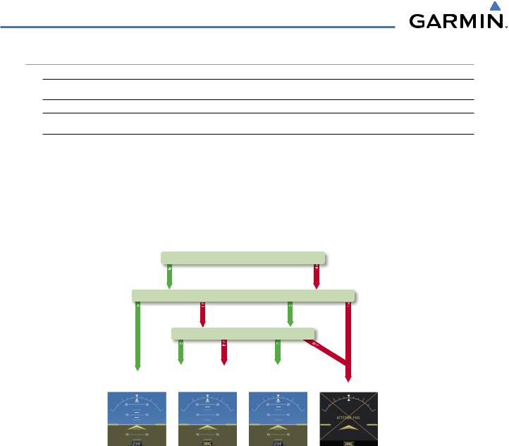
AHRS OPERATION
 NOTE: Refer to Appendix A for specific AHRS alert information.
 NOTE: Aggressive maneuvering while AHRS is not operating normally may degrade AHRS accuracy.
The Attitude and Heading Reference System (AHRS) performs attitude, heading, and vertical acceleration calculations for the G1000 System, utilizing GPS, magnetometer, and air data in addition to information from its internal sensors. Attitude and heading information are updated on the PFD while the AHRS receives appropriate combinations of information from the external sensor inputs.
Loss of GPS, magnetometer, or air data inputs is communicated to the pilot by message advisory alerts. Any failure of the internal AHRS inertial sensors results in loss of attitude and heading information (indicated by red ‘X’ flags over the corresponding flight instruments).
GPS
|
availab |
|
|
|
|
|
Magnetometer |
||
availab |
|
unavailab |
availab |
|
|
|
Airspeed Data |
||
|
availab |
unavailab |
availab |
|
AHRS Normal |
AHRS no- |
AHRS no-Mag/ |
AHRS |
|
Mag Mode |
no-Air Mode |
no-GPS |
||
Operation |
||||
Heading Invalid |
Mode |
|||
|
||||
unavailab unavailab
vailable
Attitude/Heading Invalid
Figure 1-7 AHRS Operation
GPS INPUT FAILURE
Two GPS inputs are provided to the AHRS. If GPS information from one of the inputs fails, the AHRS uses the remaining GPS input and an alert message is issued to inform the pilot. If both GPS inputs fail, the AHRS can continue to provide attitude and heading information to the PFD as long as magnetometer and airspeed data are available and valid.
MAGNETOMETER FAILURE
If the magnetometer input fails, the AHRS continues to output valid attitude information; however, the heading output on the PFD is flagged as invalid with a red ‘X’.
1-10 |
Garmin G1000 Pilot’s Guide for the Quest Kodiak 100 |
190-00590-00 Rev. C |
SYSTEM OVERVIEW
AIR DATA INPUT FAILURE
Failure of the air data input has no effect on the AHRS output while AHRS is receiving valid GPS information. Invalid/unavailable airspeed data in addition to GPS failure results in loss of all attitude and heading information.
G1000 SYSTEM ANNUNCIATIONS
 NOTE: For a detailed description of all annunciations and alerts, refer to Appendix A. Refer to the Aircraft Flight Manual (AFM) for additional information regarding pilot responses to these annunciations.
When an LRU or an LRU function fails, a large red ‘X’ is typically displayed over the instrument experiencing failed data (Figure 1-10 displays all possible flags and responsible LRUs). Upon G1000 power-up, certain instruments remain invalid as equipment begins to initialize. All instruments should be operational within one minute of power-up. If any instrument remains flagged, the G1000 should be serviced by a Garmin-authorized repair facility.
GIA 63 |
|
|
|
|
|
GIA 63 |
|
|
|
||||
|
|
|
|
|
GRS 77 or GMU 44 |
|
|
|
|
|
|
||
GEA 71
or 

 GDC 74 GIA 63
GIA 63
|
|
|
|
|
|
|
GTX 33 or GIA 63 |
|
|
|
|
|
|
|
|
||
GDC 74 |
|
|
|
|
|
|
GIA 63 |
|
|
|
|
||||||
|
|
|
|
|
|
|||
|
|
Figure 1-8 G1000 System Failure Annunciations |
||||||
|
|
|
|
|||||
190-00590-00 Rev. C |
Garmin G1000 Pilot’s Guide for the Quest Kodiak 100 |
1-11 |

SYSTEM OVERVIEW
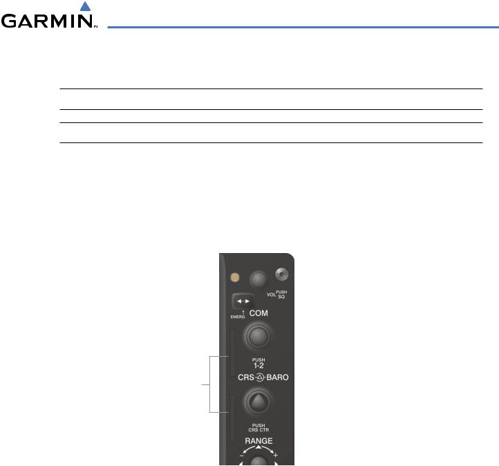
1.6 G1000 CONTROLS
PFD/MFD CONTROLS
The same controls and keys are found on both PFDs and the MFD.
(1)NAV VOL/ID Knob– Controls the NAV audio level. Press to toggle the Morse code identifier ON and OFF. Volume level is shown in the field as a percentage.
(2)NAV Frequency Toggle Key – Toggles the standby and active NAV frequencies.
(3)Dual NAV Knob – Tunes the MHz (large knob) and kHz (small knob) standby frequencies for the NAV receiver. Press to toggle the tuning cursor (light blue box) between the NAV1 and NAV2 fields.
(4)Heading Knob – Turn to manually select a heading on the HSI. When pressed, it synchronizes the heading bug with the compass lubber line.
(5)Joystick – Changes the map range (distance top to bottom of map display) when rotated. Activates the map pointer when pressed.
(6)CRS/BARO Knob – The large knob sets the altimeter barometric pressure and the small knob adjusts the course. The course is only adjustable when the HSI is in VOR1, VOR2, or OBS/SUSP mode. Pressing this knob centers the CDI on the currently selected VOR.
(7)Dual COM Knob – Tunes the MHz (large knob) and kHz (small knob) standby frequencies for the COM transceiver. Pressing this knob toggles the tuning cursor (light blue box) between the COM1 and COM2 fields.
(8)COM Frequency Toggle Key – Toggles the standby and active COM frequencies. Pressing and holding this key for two seconds automatically tunes the emergency frequency (121.5 MHz) in the active frequency field.
(9)COM VOL/SQ Knob – Controls COM audio level. Pressing this knob turns the COM automatic squelch ON and OFF. Audio volume level is shown in the field as a percentage.
(10)Direct-to Key – Allows the user to enter a destination waypoint and establish a direct course to the selected destination (specified by the identifier, chosen from the active route, or taken from the map cursor position).
(11)FPL Key – Displays the active Flight Plan Page for creating and editing the active flight plan, or for accessing stored flight plans.
(12)CLR Key (DFLT MAP)– Erases information, cancels an entry, or removes page menus. To display the Navigation Map Page immediately, press and hold CLR (MFD only).
(13)Dual FMS Knob – Used to select the page to be viewed (only on the MFD). The large knob selects a page group (MAP, WPT, AUX, NRST), while the small knob selects a specific page within the page group. Pressing the small knob turns the selection cursor ON and OFF.
(14)MENU Key – Displays a context-sensitive list of options. This list allows the user to access additional features, or to make setting changes that relate to certain pages.
(15)PROCKey–Selectsapproaches,departuresandarrivalsfromtheflightplan. Ifaflightplanisused,availableprocedures for the departure and/or arrival airport are automatically suggested. If a flight plan is not used, the desired airport and the desired procedure may be selected. This key selects IFR departure procedures (DPs), arrival procedures (STARs) and approaches (IAPs) from the database and loads them into the active flight plan.
(16)ENT Key – Accepts a menu selection or data entry. This key is used to approve an operation or complete data entry. It is also used to confirm selections and information entries.
(17)Dual ALT Knob – Sets the reference altitude in the box located above the Altimeter. The large knob selects the thousands, while the small knob selects the hundreds.
1-12 |
Garmin G1000 Pilot’s Guide for the Quest Kodiak 100 |
190-00590-00 Rev. C |
SYSTEM OVERVIEW
SOFTKEY FUNCTION
The softkeys are located along the bottoms of the displays. The softkeys shown depend on the softkey level or page being displayed. The bezel keys below the softkeys can be used to select the appropriate softkey. When a softkey is selected, its color changes to black text on gray background and remains this way until it is turned off, at which time it reverts to white text on black background.
In the following descriptions, top level softkeys are denoted by bullets.
|
|
Softkey |
|
Softkey Selection |
|||
|
|
On |
|
Box (Light Blue) |
|||
|
|
|
|
|
|
|
Softkey Names |
|
|
|
|
|
|
|
|
Bezel-Mounted |
|
|
|
(Displayed) |
|||
|
|
|
|
||||
Softkeys (Press) |
|
Figure 1-9 Softkeys (Second-Level PFD Configuration) |
|||||
|
|
||||||
The MFD/PFD Control Unit can also be used to select softkeys.
PFD SOFTKEYS.
Softkey ON |
Softkey OFF |
INSET |
|
|
|
|
|
|
|
XPDR |
|
|
|
NRST |
|
|
|
IDENT |
|
|
|||||||||||
OBS |
|
CDI |
|
|
||||||||||
|
PFD |
|
|
|
TMR/REF |
|
|
ALERTS |
Figure 1-10 PFD Top Level Softkeys
INSET – Press to display the Inset Map in the lower left corner of the PFD. OFF – Press to remove the Inset Map.
DCLTR (3) – Press momentarily to select the desired amount of map detail. The declutter level appears adjacent to the DCLTR softkey.
•Nodeclutter:Allmapfeaturesarevisible
•Declutter–1:Declutterslanddata
•Declutter–2:DeclutterslandandSUAdata
•Declutter–3:Removeseverythingexcepttheactiveflightplan TRAFFIC – Press to display traffic on the inset map.
TOPO – Press to display topographical data (i.e., coastlines, terrain, rivers, lakes) and elevation scale on the Inset Map.
190-00590-00 Rev. C |
Garmin G1000 Pilot’s Guide for the Quest Kodiak 100 |
1-13 |
SYSTEM OVERVIEW
INSET
|
|
|
|
|
|
|
|
|
|
(optional) |
(optional) |
|
(optional) |
|
|
|||
|
|
DCLTR |
|
TRAFFIC |
|
|
|
TERRAIN |
|
STRMSCP |
|
NEXRAD |
|
|
|
BACK |
|
ALERTS |
OFF |
|
|
|
TOPO |
|
|
|
|
XM LTNG |
|
|
|||||||
DCLTR-1
DCLTR-2
DCLTR-3
Press the BACK or OFF softkey to return to the top level softkeys
Figure 1-11 PFD Softkey Flow Chart – 1
TERRAIN – Press to display terrain information on the Inset Map.
STRMSCP (optional) – Press to display the Stormscope lightning data on the Inset Map (within a 200 nm radius of the aircraft).
NEXRAD (optional) – Press to display NEXRAD precipitation data on the Inset Map. XM LTNG (optional) – Press to display the XM Radio lightning data on the Inset Map. BACK – Press to return to the previous level softkey configuration.
ALERTS – Press to display the Alerts window.
PFD – Press to display the additional softkeys for additional configuration of the PFD.
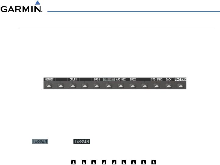
METRIC – Press to display the current and reference altitudes in meters, in addition to feet. Pressing the metric softkey also changes the barometric setting to hectopascals.
DFLTS – Press to reset default settings on the PFD.
BRG1 (bearing) – Press to cycle through the following information:
NAV1 – Displays NAV1 waypoint frequency or identifier in the BRG1 information window.
GPS – Displays GPS waypoint identifier and GPS distance information in the BRG1 information window. OFF – Removes the BRG1 information window.
PFD
METRIC |
DFLTS |
BRG1 |
360 HSI |
ARC HSI |
BRG2 |
STD BARO |
BACK |
ALERTS |
Press the DFLTS softkey to change the PFD metric values to standard
Press the STD BARO or BACK softkeys to return to the top level softkeys
Figure 1-12 PFD Softkey Flow Chart – 2
1-14 |
Garmin G1000 Pilot’s Guide for the Quest Kodiak 100 |
190-00590-00 Rev. C |
SYSTEM OVERVIEW
360 HSI – Press to display the 360° compass rose. ARC HSI – Press to display the 140° viewable arc.
BRG2 (bearing) – Press to cycle through the following information:
NAV2 – Displays NAV2 waypoint frequency or identifier in the BRG2 information window.
GPS – Displays GPS waypoint identifier and GPS distance information in the BRG2 information window. OFF – Removes the BRG2 information window.
STD BARO – Press to set the barometric pressure to 29.92 inches of mercury (1013 hPa by pressing the METRIC softkey).
BACK–Press to return to the previous level softkeys. ALERTS – Press to display the Alerts window.
OBS – Press to select OBS mode on the CDI when navigating by GPS (only available with active leg). CDI – Press to change navigation mode on the CDI between GPS, VOR1, and VOR2.
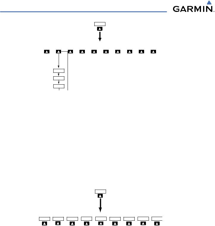
XPDR – Press to display the transponder mode selection softkeys. STBY – Press to select standby mode.
ON – Press to select mode A.
ALT – Press to select altitude reporting mode.
VFR – Press to automatically squawk 1200 (only in the U.S.A., refer to ICAO standards for VFR codes in other countries).
CODE – Press to display transponder code selection softkeys 0-7. 0 through 7 – Press numbers to enter code.
IDENT – Press to provide special aircraft position identification to Air Traffic Control (ATC).
BKSP – Press to remove numbers entered one at a time. BACK – Press to return to the previous level softkeys.
IDENT – Press to provide special aircraft position identification to Air Traffic Control (ATC). BACK – Press to return to the previous level softkeys.
ALERTS – Press to display the Alerts window.
190-00590-00 Rev. C |
Garmin G1000 Pilot’s Guide for the Quest Kodiak 100 |
1-15 |
SYSTEM OVERVIEW
IDENT – Press to provide special aircraft position identification to Air Traffic Control (ATC). TMR/REF – Press to display the Timer/References window.
NRST – Press to display the Nearest Airports window. ALERTS – Press to display the Alerts window.
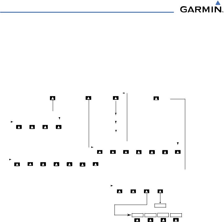
1.3MFD SOFTKEYS
ENGINE – Pressing this softkey makes available the Engine Page functions. Refer to the Engine Indication System section. MAP – Pressing this softkey enables the following softkeys:
TRAFFIC – Pressing this softkey displays/removes Traffic on the Navigation Map.
TOPO – Pressing this softkey displays or removes topographic information on the Navigation Map. TERRAIN – Pressing this softkey displays/removes terrain and obstacle data on the Navigation Map.
|
|
MAP |
|
DCLTR |
|
|
|
CHKLIST |
|
|
ENGINE |
|
|
|
|
|
|||||
|
|
|
|
|||||||
|
|
|
|
|
|
|
|
|
|
|
|
|
|
|
|
|
|
|
(optional) |
|
|
|
|
|
|
|
|
|
Press the BACK softkey |
on this level to |
|
|
|
|
|
|
|
|
|
|
|
|
|
|
|
|
|
|
|
|
|
|
|
|
|
|
|
|
|
|
|
|
||||||||||||
|
|
|
|
|
|
|
return to the top softkey level |
|
|
|
|
|
|
|
|
|
|
|
|
|
|
|
|
|
|
|
|
|
|
|
|
|
|
|
|
|
|
|
|
|
|
|
|
|
|
|||||||
|
|
|
|
|
|
|
|
|
|
|
|
|
|
|
|
|
|
|
|
|
|
|
|
|
|
|
|
|
DCLTR-1 |
|
|
|
|
|
|
|
|
|
|
|
|
|
|
|
|
|
|
|
||||
|
|
|
|
|
|
|
|
|
|
|
|
|
|
|
|
|
|
|
|
|
|
|
|
|
|
|
|
|
|
|
|
|
|
|
|
|
|
|
|
|
|
|
|
|
|
|
|
|
|
|
|
|
|
|
|
|
ENGINE |
|
|
SYSTEM |
|
FUEL |
|
|
BACK |
|
|
|
|
|
|
|
|
|
|
|
|
|
|
|
|
|
|
|
|
|
|
|
|
|
|
|
|
|
|
|
|
|
|
||||||
|
|
|
|
|
|
|
|
|
|
|
|
|
|
|
|
|
|
|
|
|
|
|
|
|
|
|
|
|
DCLTR-2 |
|
|
|
|
|
|
|
|
|
|
|
|
|
|
|
|
|
|
|
||||
|
|
|
|
|
|
|
|
|
|
|
|
|
|
|
|
|
|
|
|
|
|
|
|
|
|
|
|
|
|
|
|
|
|
|
|
|
|
|
|
|
|
|
|
|
|
|
Press to return to the |
|||||
|
|
|
|
|
|
|
|
|
|
|
|
|
|
|
|
|
|
|
|
|
|
|
|
|
|
|
|
|
|
|
|
|
|
|
|
|
|
|
|
|
|
|
|
|
|
|
||||||
|
|
|
|
|
|
|
|
|
|
|
|
|
|
|
|
|
|
|
|
|
|
|
|
|
|
|
|
|
DCLTR-3 |
|
|
|
|
|
|
|
|
|
|
|
|
|
||||||||||
|
|
|
|
|
|
|
|
|
|
|
|
|
|
|
|
|
|
|
|
|
|
|
|
|
|
|
|
|
|
|
|
|
|
|
|
|
|
|
|
|
|
|
|
|
|
|
top softkey level |
|||||
|
|
|
|
|
|
|
|
|
|
|
|
|
|
|
|
|
|
|
|
|
|
|
|
|
|
|
|
|
|
|
|
|
|
|
|
|
|
|
|
|
|
|
|
|
|
|||||||
|
|
|
|
|
|
|
|
|
|
|
|
|
|
|
|
|
|
|
|
|
|
|
|
|
|
|
|
|
|
|
|
|
|
|
|
|
|
|
(optional) |
|
(optional) |
|
(optional) |
|
|
|
||||||
|
|
|
|
|
|
|
|
|
|
|
|
|
|
|
|
|
|
|
|
|
|
|
|
|
|
|
|
|
|
|
|
|
|
|
|
|
|
|
|
|
|
|
|
|||||||||
|
|
|
|
|
|
|
|
|
|
|
|
|
|
|
|
|
|
|
|
|
|
|
|
|
|
|
|
|
|
|
|
|
|
|
|
|
|
|
|
|
||||||||||||
|
|
|
|
|
|
|
|
|
|
|
|
|
|
|
|
|
|
|
|
|
|
|
|
|
|
|
|
|
|
|
|
|
|
|
|
|
|
|
|
|
|
|
|
|||||||||
|
|
|
|
|
|
|
|
|
|
|
|
|
|
|
|
|
|
|
|
|
|
|
|
|
TRAFFIC |
|
TOPO |
|
|
|
|
|
|
|
|
|
|
|
|
|
BACK |
|
||||||||||
|
|
|
|
|
|
|
|
|
|
|
|
|
|
|
|
|
|
|
|
|
|
|
|
|
|
|
|
TERRAIN |
|
|||||||||||||||||||||||
|
|
|
|
|
|
|
|
|
|
|
|
|
|
|
|
|
|
|
|
|
|
|
|
|
|
|
|
|
|
STRMSCP |
|
NEXRAD |
|
|||||||||||||||||||
|
|
|
|
|
|
|
|
|
|
|
|
|
|
|
|
|
|
|
|
|
|
|
|
|
|
|
|
|
|
|
|
XM LTNG |
|
|
||||||||||||||||||
|
|
|
|
|
|
|
|
|
|
|
|
|
|
|
|
|
|
|
|
|
|
|
|
|
|
|
|
|
|
|
|
|
|
|
|
|
|
|
|
|
|
|
|
|
|
|
|
|
|
|
|
|
|
|
|
|
ENGINE |
|
|
SYSTEM |
|
|
|
|
|
|
|
|
|
|
|
|
|
|
|
|
BACK |
|
|
|
|
|
|
|
|
|
|
|
|
|
|
|
|
|
|
|
|
|
|
|
|
|
|
|
|
|
|
|
|
FUEL |
|
|
|
|
|
|
|
|
|
|
|
|
|
|
|
|
|
|
|
|
|
|
|
|
|
|
|
|
|
|
|
|
|
|
||||||||||||||
|
|
|
|
|
|
|
|
|
DEC FUEL |
|
INC FUEL |
|
RST FUEL |
|
|
|
|
|
|
|
|
|
|
|
|
|
|
|
|
|
|
|
|
|
|
|
|
|
|
|
|
|
||||||||||
|
|
|
|
|
|
|
|
|
|
|
|
|
|
|
|
|
|
|
|
|
|
|
|
|
|
|
|
|
|
|
|
|
|
|
|
|
|
|
|
|
|
|
|
|
|
|
|
|
|
|
|
|
|
|
|
|
|
|
|
|
|
|
|
|
|
|
|
|
|
|
|
|
|
|
|
|
|
|
|
|
|
|
|
|
|
|
|
|
The DONE softkey changes to UNDO when the checklist |
||||||||||||||||
|
|
|
|
|
|
|
|
|
|
|
|
|
|
|
|
|
|
|
|
|
|
|
|
|
|
|
|
|
|
|
|
|
|
|
|
item is already checked |
|
|
|
|
|
|
|
|
|
|||||||
|
|
|
|
|
|
|
|
|
|
|
|
|
|
|
|
|
|
|
|
|
|
|
|
|
|
|
|
|
|
|
|
|
|
|
|
|
|
|
|
|
|
|
|
|
|
|
||||||
|
|
|
|
|
|
|
|
|
|
|
|
|
|
|
|
|
|
|
|
|
|
|
|
|
|
|
|
|
|
|
|
|
DONE |
|
|
EXIT |
|
EMERGCY |
|
|
|
|
|
|||||||||
|
|
|
|
|
|
|
|
|
|
|
|
|
|
|
|
|
|
|
|
|
|
|
|
|
|
|
|
|
|
ENGINE |
|
|
|
|
|
|
|
|||||||||||||||
|
|
|
|
|
|
|
|
|
|
|
|
|
|
|
|
|
|
|
|
|
|
|
|
|
|
|
|
|
|
|
|
|
|
|
|
|
|
|
|
|||||||||||||
|
|
CLR |
|
ENGINE |
MAP |
DCLTR |
CHKLIST |
Figure 1-14 MFD Softkeys
STRMSCP (optional) – Pressing this softkey displays/removes Stormscope lightning data on the Navigation Map. NEXRAD (optional) – Pressing this softkey displays/removes precipitation data on the Navigation Map.
XM LTNG (optional) – Pressing this softkey displays/removes XM Radio lightning data on the Navigation Map. BACK – Pressing this softkey displays the ENGINE and MAP top level softkeys.
DCLTR (declutter) – Pressing this softkey removes map information in three levels.
1-16 |
Garmin G1000 Pilot’s Guide for the Quest Kodiak 100 |
190-00590-00 Rev. C |

SYSTEM OVERVIEW
The NAV, CRS/BARO, COM, FMS, and ALT knobs are concentric dual knobs, each having small (inner) and large (outer) control portion. When a portion of the knob is not specified in the text, either may be used.
Large (Outer)
Knob
Small (Inner)
Knob
Figure 1-15 Dual Concentric Knob
190-00590-00 Rev. C |
Garmin G1000 Pilot’s Guide for the Quest Kodiak 100 |
1-17 |
SYSTEM OVERVIEW
1.7 ACCESSING G1000 FUNCTIONALITY
MENUS
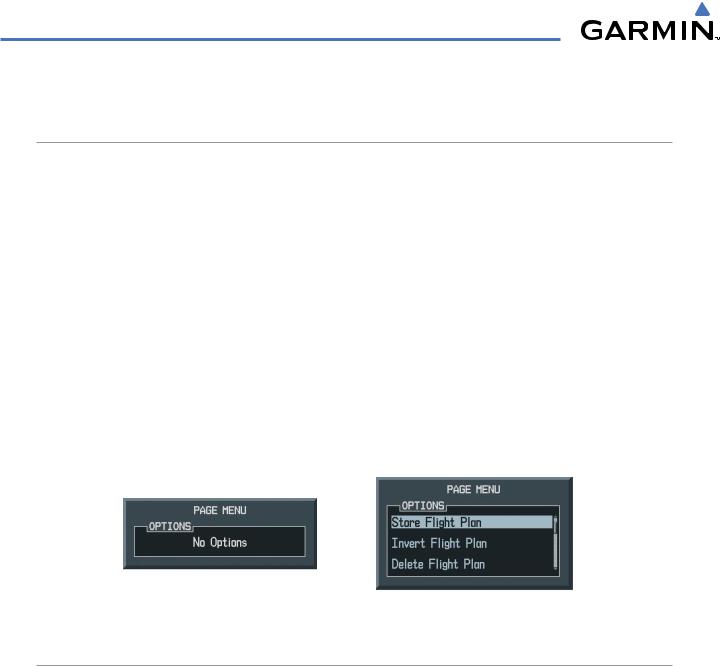
The G1000 has a dedicated MENU Key that when pressed displays a context-sensitive list of options. This options list allows the user to access additional features or make settings changes which specifically relate to the currently displayed window/page. There is no all-encompassing menu. Some menus provide access to additional submenus that are used to view, edit, select, and review options. Menus display ‘NO OPTIONS’ when there are no options for the window/page selected. The main controls used in association with all window/page group operations are described in Section 1.6, G1000 Controls. Softkey presses do not display menus or submenus.
Navigating a menu:
1)Press the MENU Key to display the menu.
2)Turn the FMS Knob to scroll through a list of available options (a scroll bar always appears to the right of the window/box when the option list is longer than the window/box).
3)Press the ENT Key to select the desired option.
4)Press the CLR Key or FMS Knob to remove the menu and cancel the operation.
No Options for |
Options for FPL Window |
NRST Window |
|
Figure 1-16 Page Menu Examples
DATA ENTRY
Using the FMS Knob to enter data:
1)If needed, press the FMS Knob to activate the cursor.
2)Use the large FMS Knob to highlight the desired field.
3)Begin entering data by turning the small FMS Knob to select a character for the first placeholder.
Turning the knob to the right scrolls through the alphabet (where appropriate) toward the letter Z, starting in the middle at K, and the digits zero through nine. Turning the knob to the left scrolls in the opposite direction.
4)Use the large FMS Knob to move the cursor to the next placeholder in the field.
5)Repeat, using the small FMS Knob to select a character and the large FMS Knob to move the cursor, until the field is complete. Press the ENT Key to confirm entry.
6)Press the FMS Knob or CLR Key to cancel data entry (the field reverts back to its previous information).
1-18 |
Garmin G1000 Pilot’s Guide for the Quest Kodiak 100 |
190-00590-00 Rev. C |
SYSTEM OVERVIEW
PAGE GROUPS
 NOTE: Refer to other supporting sections in this Pilot’s Guide for details on specific pages.
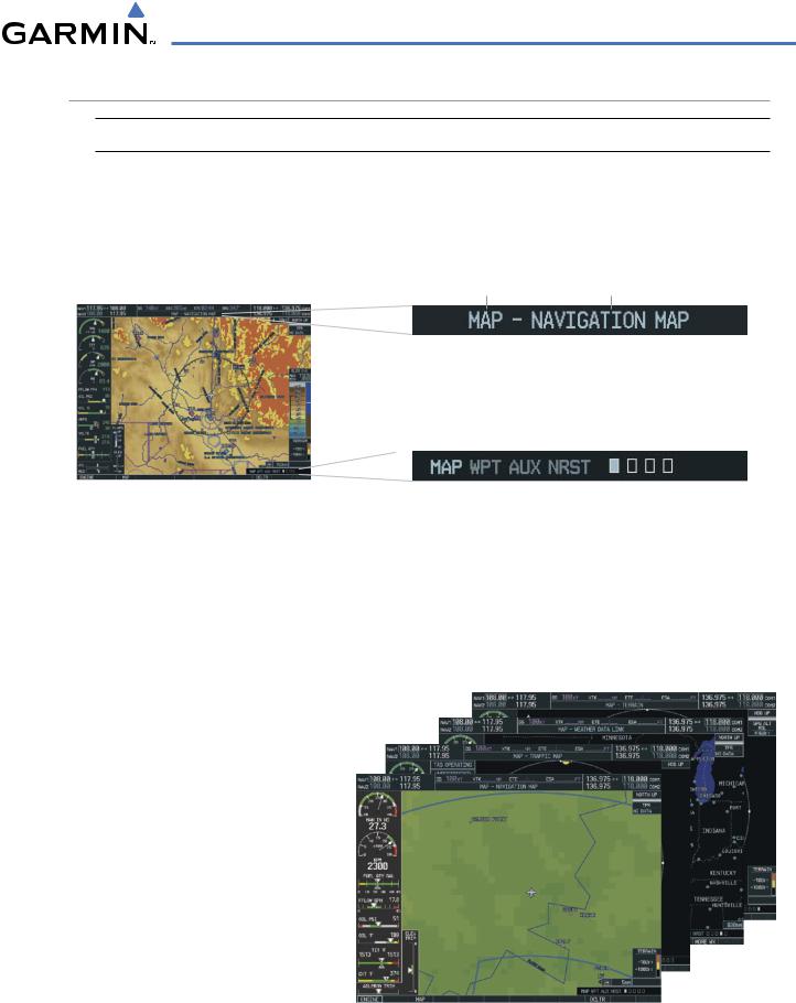
Information on the MFD is presented on pages which are grouped according to function. The page group and active page title are displayed in the upper center of the screen, below the Navigation Status Box. In the bottom right corner of the screen, the current page group, number of pages available in the group, and placement of the current page within the group are indicated by icons. For some of these pages (Airport/Procedure/Weather Information, XM, Procedure Loading), the title of the page may change while the page icon remains the same.
Page Group |
Active Page Title |
Figure 1-17 Page Title
|
Page Groups |
Pages in Current Group |
|||||
|
|
|
|
|
|
|
|
MFD |
|
|
|
|
Selected Page |
||
|
|
|
|
||||
|
|||||||
|
Figure 1-18 |
Page Group Icons |
|||||
There are four main page groups, navigated using the FMS Knob; specific pages within each group can vary depending on the configuration of optional equipment.
Selecting a page using the FMS Knob:
1)Turn the large FMS Knob until the desired page group is selected.
2)Turn the small FMS Knob until the desired page is selected.
•Map Page Group (MAP)
Navigation Map Traffic Map
Weather Data Link (optional) Terrain/TAWS (TAWS optional)
Figure 1-19 Map Pages
190-00590-00 Rev. C |
Garmin G1000 Pilot’s Guide for the Quest Kodiak 100 |
1-19 |

SYSTEM OVERVIEW
•Waypoint Page Group (WPT)
Airport/Procedures/Weather Information Pages
-Airport Information (INFO Softkey)
-Departure Information (DP Softkey)
-Arrival Information (STAR Softkey)
-Approach Information (APR Softkey)
-Weather Information (optional) (WX Softkey)
Intersection Information
NDB Information |
|
|
|
|
Airport/Procedures/ |
VOR Information |
|
|
|
|
Weather Information |
|
|
|
|
||
|
|
|
|
Pages |
|
User Waypoint Information |
Figure 1-20 Waypoint Pages |
||||
|
|||||
•Auxiliary Page Group (AUX)
Trip Planning Utility
GPS Status System Setup
XM Satellite screens (optional)
-XM Information (INFO Softkey)
-XM Radio (RADIO Softkey)
System Status
XM

 Pages
Pages
Figure 1-21 Auxiliary Pages
1-20 |
Garmin G1000 Pilot’s Guide for the Quest Kodiak 100 |
190-00590-00 Rev. C |
Loading...