


 Loading...
G1000TM
AFCS Pilot’s Guide for Beechcraft A36/G36

|
|
Record of Revisions |
|
|
|
|
|
Revision |
Date of Revision |
Revision Page Range |
Description |
A |
07/20/05 |
9-1 – 9-29 |
Initial release |
B |
07/28/05 |
9-1 – 9-29 |
GoAround button description change |
|
|
|
|
Garmin G1000 AFCS Pilot’s Guide for Beechcraft A36/G36 |
190-00609-00 Rev. B |

9.1 INTRODUCTION
NOTE: This Pilot’s Guide assumes that the reader is already familiar with the G1000 Integrated Cockpit System. Refer to the G1000 Cockpit Reference Guide and G1000 Pilot’s Guides for further information concerning the G1000 system.
IMPORTANT: The information contained in this guide is always superseded by the approved Airplane Flight Manual Supplement.
AFCS OVERVIEW
TheGFC 700isadigitalAutomaticFlightControlSystem (AFCS) which is fully integrated within the G1000 system avionics architecture. The System Overview located near the front of this binder provides a block diagram to support this system description. The GFC 700 AFCS is made up of the following Line Replaceable Units (LRUs):
•GDU 1040 Primary Flight Display (PFD)
•GDU 1043 Multi-Function Display (MFD)
•GIA 63 Integrated Avionics Units (2)
•GSA 81 Servos (4)
•GSM 85 Servo Mounts (4)
The GFC 700 AFCS system can be divided into three main operating functions:
Flight Director — Flight Director operation takes place within the #1 GIA 63 and the GDU 1040 PFD. The Flight Director provides the system with:
•Command Bars showing Pitch/Roll Guidance
•Pitch/Roll Mode Selection & Processing
•Autopilot Communication
INTRODUCTION
Autopilot — Autopilot operation occurs within the pitch, roll, and pitch trim GSA 81 servos and provides:
•Automatic Flight Control
•Servo Monitoring
YawDamper—Yawdamperoperationisprovidedby the GSA 81 yaw servo and includes self monitoring.
GIA 63 Integrated Avionics Units
Each GIA 63 contains the AFCS software which controls the Flight Director. During normal operation, the GRS 77 AHRS and GDC 74A Air Data Computer send attitude and air data information to the GIA 63s. This information, combined with GPS and other system data, is used by the Flight Director and Autopilot. Flight Director commands are calculated within the #1 GIA 63 and are sent to the PFD for display and mode annunciation. Flight information is also sent to the GSA 81 servos for Autopilot operation. A GIA #1 failure results in the loss of the AFCS system. Any GIA 63 failure results in loss of the Autopilot, Manual Electric Trim, and the Yaw Damper functions.
190-00609-00 Rev. B |
Garmin G1000 AFCS Pilot’s Guide for Beechcraft A36/G36 |
9-1 |
INTRODUCTION
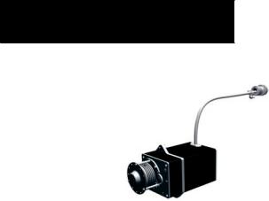
GSA 81 AFCS Servos (4)
Four GSA 81 servos are used for automatic control of the aircraft flight control surfaces. One servo is used for the each of the following:
•Pitch
•Roll
•Pitch Trim
•Yaw
Each servo moves its respective aircraft control surface in response to commands generated by internal servo calculations. For pitch trim, the servo positions the aircraft pitch trim surface in response to commands generated by automatic and manual electric pitch trim calculations. Calculations are performed using data sent through the common serial data bus from the GIA 63. Manual electric pitchtrimisalsoprovidedinresponsetotheManualElectric Trim (MET) switch.
GSM 85 Servo Mounts (4)
The GSM 85 servo mounts are used to connect the servos to the aircraft control system. They contain a spiral capstan which connects via a bridle cable to the main aircraft control cables. There is also a slip clutch to limit overpower forces in the unlikely event of a mechanical jam. An engage clutch is used to disconnect the capstan from the servo when the AFCS is disengaged.
Dedicated AFCS Controls
Refer to Figure 2.3.1 located in the System Overview. The GDU 1043 MFD has the following dedicated AFCS keys located on the lower left side of the bezel:
•AP Key – Engages/disengages the Autopilot
•FD Key – Activates/deactivates the Flight Director only
Pressing the FD key turns on the Flight Director in the default vertical and lateral modes. Pressing the FD key again deactivates the Flight Director and removes the command bars, unless the Autopilot is engaged. If the Autopilot is engaged, the FD key is disabled.
•NAV Key – Selects/deselects the Navigation mode
•ALT Key – Selects/deselects the Altitude Hold mode
•VS Key – Selects/deselects the Vertical Speed mode
•FLC Key – Selects/deselects the Flight Level Change mode
•YD Key – Engages/disengages the Yaw Damper
•HDG Key – Selects/deselects the Heading Select mode
•APR Key – Selects/deselects the Approach mode
•NOSE UP/NOSE DN Keys – Controls the active pitch reference for the Pitch Hold, Vertical Speed, and Flight Level Change modes
9-2 |
Garmin G1000 AFCS Pilot’s Guide for Beechcraft A36/G36 |
190-00609-00 Rev. B |

Additional AFCS Controls
The following buttons and switches used by the AFCS are located in the cockpit separately from the PFD and MFD:
•AP DISC (Autopilot Disconnect) Button —
Disengages the Autopilot and Yaw Damper and interrupts pitch trim operation
This button may be used to mute the aural alert associated with an Autopilot disconnect. The AP DISC button is colored red and is located forward of the MET switch on the pilot’s control wheel left grip. The AP DISC button mutes AP disconnect alerting if pressed during an alert. The MET ARM switch may also be used to cancel AP disconnect alerting.
•CWS (Control Wheel Steering) Button —
Momentarily disengages the Autopilot and synchronizes the Flight Director’s command bars to the current aircraft attitude
The CWS button is located on top of the right grip of the pilot’s control wheel. Upon release of the CWS button, the Flight Director may establish new reference points, depending on the current pitch and roll modes. CWS operation details are discussed in the respective mode sections of this manual.
•GA (Go Around) Button — Disengages the Autopilot and selects the Go Around pitch and roll modes on the Flight Director
The GA button is located in the throttle handle.
INTRODUCTION
•MET (Manual Electric Trim) Switch — Used to command Manual Electric Pitch Trim
This switch is a composite switch, split into left and right switches, on the left grip of the pilot’s control wheel. The right switch is the ARM contact and the left switch controls the DN (forward) and UP (rearward) contacts. Pressing the ARM switch disengages the Autopilot, if currently engaged, but does not affect Yaw Damper operation. Manual trim commands are generated only when both sides of the switch are operated simultaneously. If one side of the switch is active for more than three seconds without the other side also being active, the trim switches are ignored until both switches (ARM, UP/DN) are inactive. This condition is annunciated as ‘PTRM’ in the AFCS System Status field on the PFD.
190-00609-00 Rev. B |
Garmin G1000 AFCS Pilot’s Guide for Beechcraft A36/G36 |
9-3 |

INTRODUCTION
This page intentionally left blank
9-4 |
Garmin G1000 AFCS Pilot’s Guide for Beechcraft A36/G36 |
190-00609-00 Rev. B |
FD OPERATION
9.2 FLIGHT DIRECTOR OPERATION Activating the Flight Director
The Flight Director function provides pitch and roll commands to the AFCS system and displays them on the PFD. With the Flight Director activated, the pilot can hand-fly the aircraft to follow the path shown by the command bars. The Flight Director, when engaged, also provides the commands to the Autopilot.
Pressing the FDkey or APkey (when FD is not active) activates the Flight Director in default pitch/roll modes. Pressing the GAbutton, or any other Fight Director mode keyactivatestheFlightDirectorin therespectivemode(s). When active, the Flight Director may be turned off by pressing the FD key, if the Autopilot is not engaged.
NOTE: The FD key is disabled when theAutopilot is engaged.
|
|
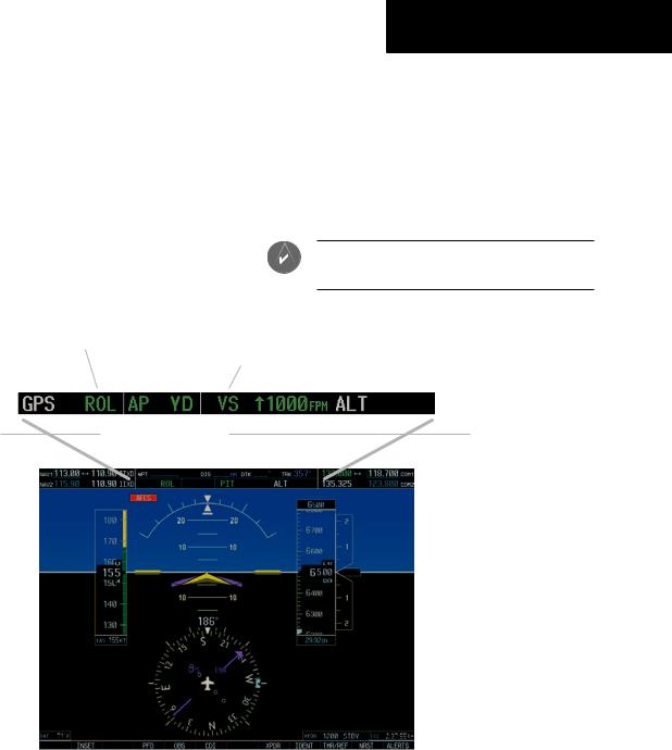
Active Mode Yaw Damper Status |
Mode Reference |
|
|
|
||||
Armed Mode |
Autopilot Status |
Active Mode |
|
Armed Mode |
||||||
|
|
|
|
|
|
|
|
|
|
|
|
|
|
|
|
|
|
|
|
||
Roll Axis Modes |
|
|
|
|
|
|
|
|
|
Pitch Axis Modes |
|
|
|
|
AFCS Status Bar |
|
|
||||
|
|
|
|
|
|
|
|
|||
System Status Field |
|
|
|
|
|
Selected Altitude |
|
|
|
|
|
||
(See Annunciations & |
|
|
|
|||
|
|
|
Box |
|||
Alerts Pilot’s Guide) |
|
|
|
|||
|
|
|
|
|||
Flight Director |
|
|
|
|
||
Command Bars |
|
|
|
|
|
|
Figure 9.2.1 PFD AFCS Display
190-00609-00 Rev. B |
Garmin G1000 AFCS Pilot’s Guide for Beechcraft A36/G36 |
9-5 |

FD OPERATION
AFCS Status Bar
Flight Director mode annunciations are displayed on the PFD, whenever the Flight Director is active. Figure 9.2.1 shows each individual AFCS Status Bar field. Roll modes are displayed on the left side and pitch modes are displayed on the right. Armed modes are displayed in white and active modes are displayed in green. Refer to Section 9.3 for Flight Director mode information.
Command Bars
Uponactivation,theFlightDirectordisplayscommand bars on the PFD. Figure 9.2.2 shows the command bars. The command bars move together vertically to indicate pitch commands, and will bank left or right to indicate roll commands. If the attitude information being sent to the Flight Director becomes invalid or unavailable, the command bars are removed from the display.
Figure 9.2.2 Command Bars
Flight Director Limitations
The maximum commanded pitch and roll attitudes are limited to values established during AFCS certification. Maximum commanded pitch and roll rates are also limited. Pitch commands are limited to 20 degrees nose up and 15 degrees nose down. Roll commands are limited to 22 degrees of bank and a 5 degrees/second bank rate. Limits may be different from these values in certain modes, as noted in the section for the mode operation.
9-6 |
Garmin G1000 AFCS Pilot’s Guide for Beechcraft A36/G36 |
190-00609-00 Rev. B |
9.3 FLIGHT DIRECTOR MODES
Flight Director modes are normally selected independently for the pitch and roll axes. Unless otherwise specified, all mode keys are alternate action (i.e. press on, press off).
PITCH MODES
The GFC 700 AFCS offers the following pitch modes:
•Pitch Hold (default)
•Altitude Hold
•Vertical Speed
•Flight Level Change
•Glideslope
•Go Around
Table 9.3.1 equates each pitch mode to the respective key or switch, and gives accompanying mode annunciations. Mode annunciations for pitch modes are shown in green during normal operation.
Mode |
Pitch |
Annunciation |
Key |
Mode |
Window |
{default} |
Pitch Hold |
PIT |
ALT |
Altitude Hold |
ALT FT nnnnn |
VS |
Vertical Speed |
VS FPM nnnn |
FLC |
Flight Level Change |
FLC KT nnn |
APR |
Glideslope |
GS |
GOAROUND |
GoAround |
GA |
Table 9.3.1 Pitch Modes
FD MODES
Overspeed Protection
While Vertical Speed, Flight Level Change, or default Pitch Hold modes are selected, airspeed is monitored by the Flight Director. In these modes, pitch commands are limited to provide overspeed protection. Overspeed protection occurs in situations where the Flight Director cannot acquire and maintain the pitch mode reference for the selected pitch mode without exceeding the certified maximum Autopilot airspeed.
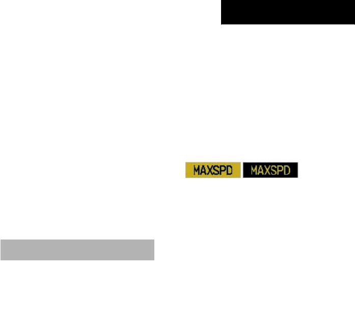
When in overspeed mode, the airspeed reference box appears above the airspeed tape, flashing alternatively between the annunciations depicted in the figure below:
Figure 9.3.1 Overspeed Annunciations
When an Autopilot overspeed warning occurs, the pilot should reduce engine power and/or adjust the pitch reference to slow the aircraft. When the overspeed condition is resolved, the annunciation disappears and the previous pitch mode resumes control.
190-00609-00 Rev. B |
Garmin G1000 AFCS Pilot’s Guide for Beechcraft A36/G36 |
9-7 |

FD MODES
Pitch Hold Mode (PIT)
When the Flight Director is activated (the FD key is pressed), Pitch Hold is selected by default. Pitch Hold mode is indicated by the annunciation ‘PIT’ appearing in the active pitch mode field in green. In Pitch Hold mode, the Flight Director maintains a constant pitch attitude, known as a pitch reference. The pitch reference conforms to the aircraft attitude at the moment of engagement.
Pitch Hold mode is active
Flight Director command bars maintain desired pitch reference
Changing the Pitch Reference
When operating in Pitch Hold mode, the pilot can adjust the pitch reference using the NOSE UP/NOSE DN keys in 0.5-degree increments. Flight Director pitch reference can also be changed by pressing the CWS button, hand-flying the aircraft to establish a new pitch reference, then releasing the CWS button.
Altitude Hold mode is armed
Figure 9.3.2 Pitch Hold Mode
9-8 |
Garmin G1000 AFCS Pilot’s Guide for Beechcraft A36/G36 |
190-00609-00 Rev. B |
Loading...