


2000

Valtek StarPac II
Intelligent Control System
Valtek Logix Series 2000
Digital Positioner
GENERAL INFORMATION
The following instructions are designed to assist in
unpacking, installing and performing maintenance as
required on Valtek® StarPac® II Intelligent Control
Systems and LogixTM 2000 Digital Positioners. Product
users and maintenance personnel should thoroughly
review this bulletin prior to installing, operating, or
performing any maintenance on the valve.
More detailed operation instructions are included
in the StarPac II / Logix 2000 Manual; refer to them
when more information is needed.
Separate Valtek Installation, Operation, Maintenance
instructions cover the valve (IOM 1 or IOM 27) and
actuator (IOM 2 or IOM 31) portions of the system and
other accessories. Refer to the appropriate instructions
when this information is needed.
To avoid possible injury to personnel or damage to valve parts, users must strictly adhere
to WARNING and CAUTION notes. Modifying
this product, substituting non-factory parts,
or inferior parts, or using maintenance procedures other than outlined could drastically
affect performance and be hazardous to personnel and equipment, and may void existing
warranties.
WARNING: Standard industry safety practices must
be adhered to when working on this, or any, process
control product. Specifically, personal protective
and lifting devices must be used as warranted.
Unpacking
1. While unpacking the StarPac II / Logix 2000 unit,
check the packing list against the materials received. Lists describing the system and accessories are included in each shipping container.
2. When lifting the system from the shipping container,
position lifting straps to avoid damage to tubing and
mounted accessories. Systems with valves up to
eight inches may be lifted by actuator lifting ring. On
larger systems, lift unit using lifting straps or hooks
through the yoke legs and outer end of body.
WARNING: When lifting a valve/actuator assembly with lifting straps, be aware the center
of gravity may be above the lifting point. Therefore, support must be given to prevent the
valve/actuator from rotating. Failure to do so
can cause serious injury to personnel or damage to nearby equipment.
3. In the event of shipping damage, contact your
shipper immediately.
4. Should any problem arise, contact your Valtek
Control Valve representative.
Valtek No. 133389
Flowserve Corporation, Valtek Control Products, Tel. USA 801 489 8611
Flowserve Corporation, Valtek Control Products, Tel. USA 801 489 8611
42-1
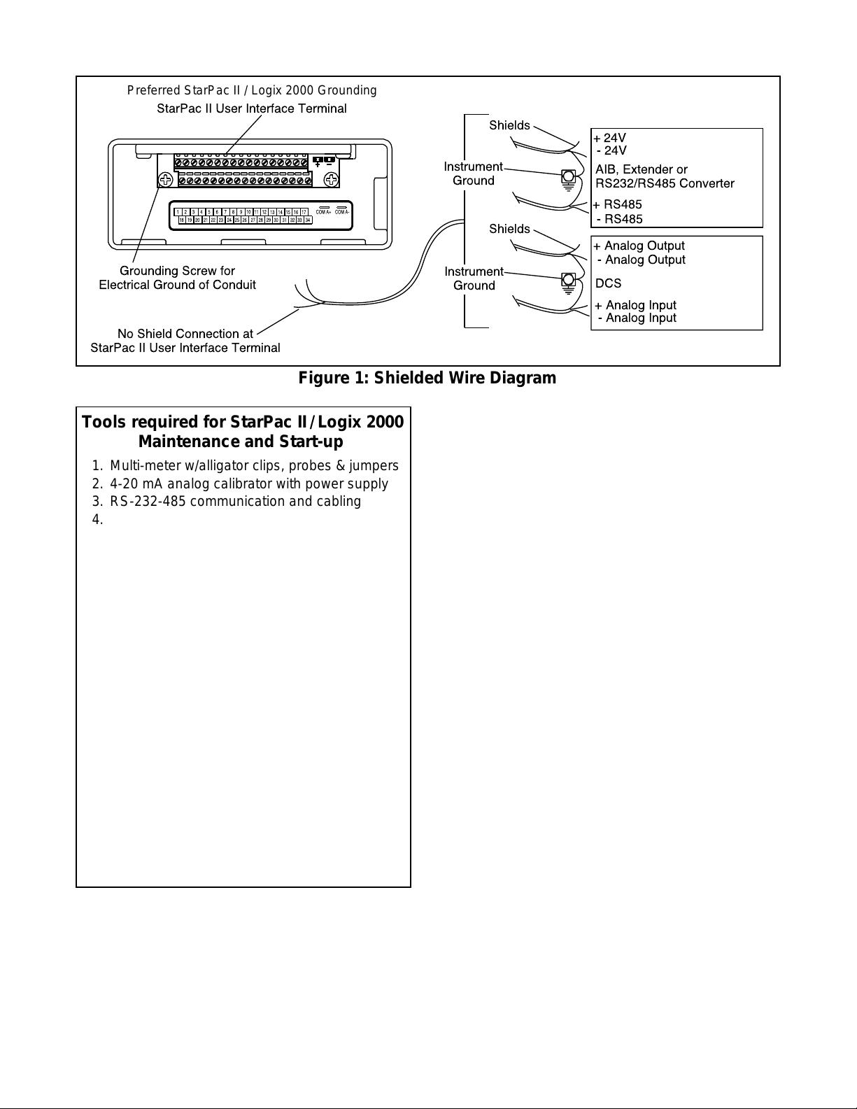
Preferred StarPac II / Logix 2000 Grounding
StarPac II User Interface Terminal
Grounding Screw for
Electrical Ground of Conduit
No Shield Connection at
StarPac II User Interface Terminal
Shields
Instrument
Ground
Shields
Instrument
Ground
Figure 1: Shielded Wire Diagram
+ 24V
- 24V
AIB, Extender or
RS232/RS485 Converter
+ RS485
- RS485
+ Analog Output
- Analog Output
DCS
+ Analog Input
- Analog Input
Tools required for StarPac II / Logix 2000
Maintenance and Start-up
1. Multi-meter w/alligator clips, probes & jumpers
2. 4-20 mA analog calibrator with power supply
3. RS-232-485 communication and cabling
4. Windows
TM
compatible PC
5. Standard 6-inch flat screwdriver
6. Standard phillips screwdriver
7.1/4-inch flat screwdriver
8. Small wire cutter (flush cut) & wire strippers
9. Needle-nose pliers
10.1/16-inch allen wrench
11. Vise grips
12. Small vise grips
13.1/2-inch nut driver
14.5/32-inch allen wrench
15. Large crescent wrench (minimum 15-inch)
16. 8-inch channel lock pliers
17.3/32-inch screwdriver
18. Wrist grounding strap
19. Antistatic bag or packaging
20. EPROM remover (PLCC type)
21. Electrical tape
22. Feedback shaft tool and drive module
pressure calibration connectors (supplied
with feedback module kit)
INSTALLATION
Valve Installation
The StarPac II / Logix 2000 Intelligent Control System
valve is installed in the same manner as a conventional
control valve and according to industry standards. Refer
to the appropriate valve installation, operation, maintenance instructions for proper installation procedures.
If the StarPac II is being installed in an insulated process
line, do not place more than four inches of insulation
around the pressure or temperature sensors; otherwise
the sensors may not operate properly. In addition,
NEVER
insulate the unit electronics assembly or
remote-mounted temperature/pressure sensors (when
used).
CAUTION: Do not insulate the StarPac II / Logix
2000 electronics housing or remote-mounted pressure or temperature sensors; otherwise excessive
heat may build up and affect operation.
Wiring and Grounding Guidelines
This section will help you achieve a maximum “noise -free”
environment and performance with a StarPac II / Logix
2000 unit.
Shielding Versus Grounding
All signals to the StarPac II / Logix 2000 unit should be
in shielded cables. Shields must be tied to a ground at
only one end of the cable to provide a place for environmental electrical noise to be removed from the cable. A
ground wire (unlike a shield) is attached at both ends to
provide a continuous path for electrical conductivity.
Grounding Screw
The green grounding screw by the user interface terminal block should be used to provide the unit with an
adequate and reliable earth ground reference. This
ground should be tied to the same ground as the
electrical conduit. Additionally, the electrical conduit
connecting to the unit should be earth grounded at both
ends of its run.
used to terminate signal shield wires.
24VDC Power
The 24 VDC connection points will work best with
shielded twisted pair wire with the shield wire connected
The green grounding screw must not be
42-2
Flowserve Corporation, Valtek Control Products, Tel. USA 801 489 8611
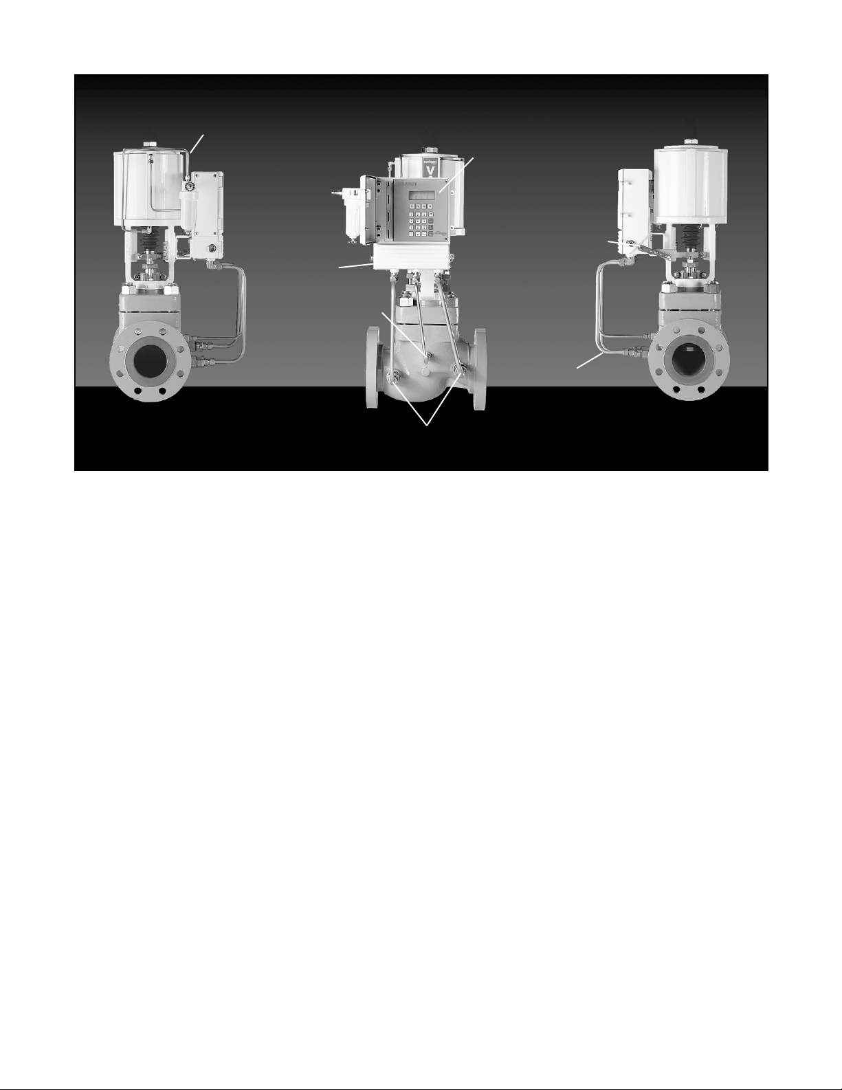
Air Lines to
Cylinder Actuator
Electronics Module
with Keypad and
Local Display
User Access
Terminal
Behind
Lower Door
Temperature
Sensor
Process Pressure Sensors
Figure 2: StarPac II / Logix 2000 Intelligent Control System Components
only at the source. The input power is isolated within the
unit and may be referenced to whatever level is necessary.
connected to earth ground.
RS-485 Communication
RS-485 wiring requires the use of a shielded twisted
pair cable, which is grounded only at the source and not
in the unit. (For maximum performance, wire should
have a characteristic impedance of 120 ohms.) The
RS-485 input is fully isolated, using opto-isolators.
The RS-485 allows only a 7 to 12 V common mode
voltage differential between stations. Valtek's RS-232
to RS-485 converter is not a grounded connection.
PC's with internal RS-485 cards, on the other hand, are
often grounded. If another ground communication
device is on the network, a fault condition will almost
certainly exist due to transient and steady state differences in ground potential.
4 - 20 mA Command Input, Auxiliary Input, and
Feedback Output
These signals are isolated but shielded twisted pair wire
should be used to reduce crosstalk from other signals.
The shield should be connected only at the source.
Discrete Inputs and Outputs
These signals are isolated, but because they are frequently used to switch high voltage (120 VAC), they
should be run in separate shielded wire paths away
from the other StarPac II / Logix 2000 signals.
The 24 VDC power supply should not be
Position
Feedback
Arm
Electronics
Conduit
AIB and RS-232 to RS-485 Converter Connection
When connecting a StarPac II / Logix 2000 unit to a
communication device, no shield or ground connections exist. Hence, the 24 VDC power and RS-485
communication shield drain wires must be connected to
a convenient ground near the AIB or converter.
Wiring The StarPac II / Logix 2000 System
All electrical connections must be done according to
local and industry electrical codes. Valtek recommends
a shielded cable be used for the RS-485 command
signal wire (e.g., Belden 9841 or equivalent).
When connecting multiple StarPac II / Logix 2000 units,
a parallel daisy-chain wiring pattern is used. Connect
unit's branch lines to main line, keeping branch lines as
short as possible. The total length of wiring should not
exceed 4,000 feet (1,200 meters) without use of repeaters.
Avoid devices producing electrical 'noise' while installing the cable.
CAUTION: The following procedure should be performed on the bench or with the unit isolated so that
unexpected valve stroking will not adversely affect
the process.
WARNING: The following procedures may cause
the valve to stroke, causing pressures and temperatures to vary from their norms. Notify appropriate personnel that the valve may stroke unexpectedly. Valtek suggests that the system be isolated
from the process, if installed in line.
Flowserve Corporation, Valtek Control Products, Tel. USA 801 489 8611
42-3
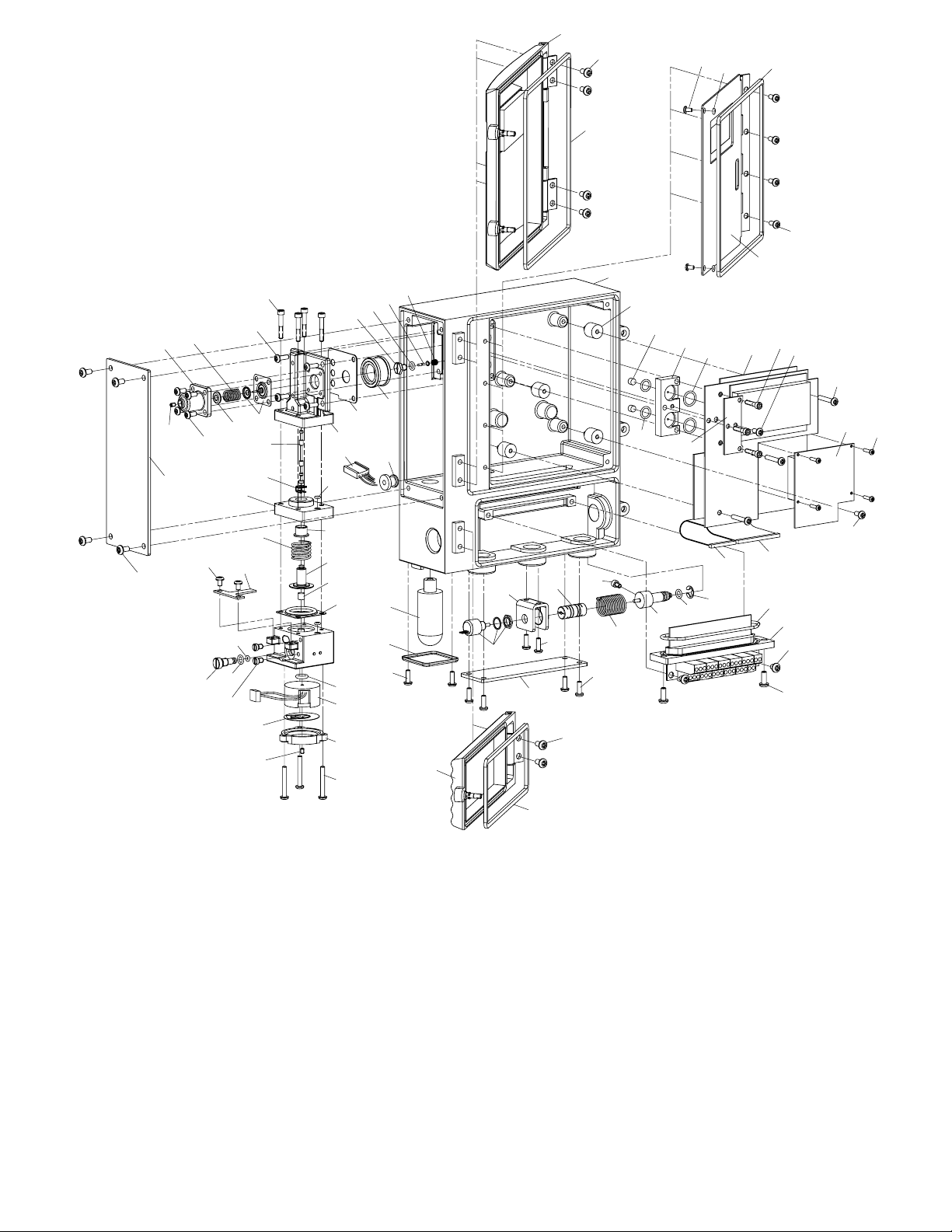
1
2
3
52
48
46
44
45
11
50
49
47
59
60
62
55
53
51
83
61
58
57
56
54
42
43
29
31
80
81
30
32
33
35
82
8
7
36
37
34
38
40
41
64
68
12
69
72
71
70
73
76
1. Upper door assembly
2. Door screw (4)
3. Upper door gasket
4. Lower door assembly
5. Door screw (2)
6. Lower door gasket
7. Inner door/keypad assembly
8. Inner door screw (4)
9. Feedback cover assembly
10. Cover screw (4)
11.Driver cover assembly
12. Cover screw (4)
13. Hydrophobic filter cover
14. Cover screw (2)
15. Hydrophobic filter
16. Hall potentiometer assembly
17. Potentiometer bracket
18. Flex couple
19. Bracket screws (2)
20. Torsional spring
21. Feedback shaft
22. Shaft O-ring
23. Retaining ring
24. Screw, hard stop
25. Feedthrough assembly
26. Feedthrough O-ring
27. Board screw (2)
28. Block screw (2)
63
65
66
67
74
75
77
78
79
29. Isolator (4)
30. Filter (2)
31. Adapter O-ring, lower (2)
32. Pressure sensor adapter
33. Adapter O-ring, upper (2)
34. StarPac II / Logix 2000
board assembly
35. Board stiffener
36. Board assembly screw (3)
37. Board stiffener screw
38. Board assembly screw (3)
39. Board assembly screw
40. Personality card
41. Personality card screw (4)
42. Rubber grommet (2)
43. Housing assembly
15
13
14
4
17
16
18
19
9
5
6
Figure 3: Exploded View
44. Regulator set screw
45. Regulator housing screw (4)
46. Regulator housing
47. Spring button
48. Regulator spring
49. Regulator diaphragm
assembly
50. Driver module mounting
screw (4)
51. Pilot valve
52. Pilot valve screw (4)
53. Pilot valve gasket
54. Regulator filter
55. Poppet guide
56. Poppet O-ring
57. Poppet
39
85
24
23
22
21
20
10
84
26
25
27
28
58. Poppet spring
59. Spool
60. Spool clip
61. Driver manifold O-ring
62. Driver spacer
63. Driver bearing
64. Spool return spring
65. Driver piston
66. Magnet
67. Driver manifold diaphragm
68. T-board screw (2)
69. T-board
70. Orifice screw
71. Orifice screw O-ring
72. Orifice O-ring
73. Testing plug (2)
74. Coil O-ring
75. Pressure modulator
assembly
76. Spring diaphragm
77. Modulator cover
78. Modulator set screw
79. Modulator screw (3)
80. Inner door screw (2)
81. Inner door screw O-ring (2)
82. Keypad gasket
83. Wire harness
84. 24-pin ribbon cable
85. 14-pin ribbon cable
42-4
Flowserve Corporation, Valtek Control Products, Tel. USA 801 489 8611
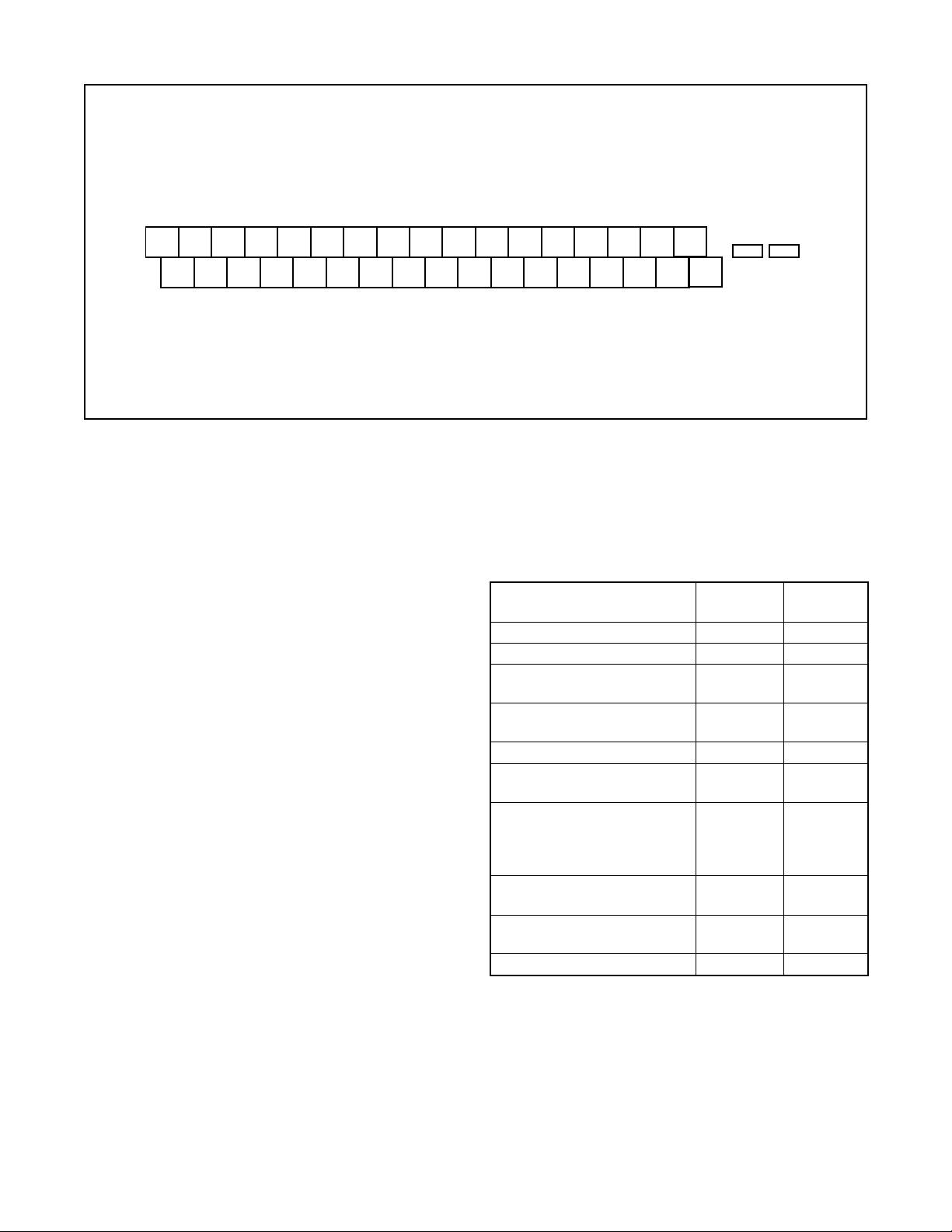
out -
out +
out -
1
1
Analog
out +
Analog
Spare
Com B -
Com B +
Com A -
Com A +
24 VDC -
24 VDC +
Grnd (Blk)
out - (Wht)
1
P
out + (Grn)
1
P
P
+5 VDC (Red)
1
1
P
Thrm Coup (Yel)
2
2
Thrm Coup (Red)
Analog
Analog
1 2 3 4 5 6 7 8 9 10 1112 131415 1617
18 19 20 21 22 23 24 25 26 27 28 29 30 31 32 33 34
Com A +
Com A -
Grnd (Blk)
out - (Wht)
2
P
out + (Grn)
2
P
P
in -
2
2
Analog
+5 VDC (Red)
2
P
in +
1
2
Analog
in -
in +
1
Analog
Analog
Spare
Figure 4: User Interface Terminal Pinouts
To connect the wiring to the StarPac II / Logix 2000 unit,
refer to Figures 1 and 4, and Table I, then proceed as
follows.
1. Open the lower door on the front of the housing.
WARNING: Do not open the electronic housing
covers in flammable atmospheres; otherwise,
possible injury to personnel or equipment may
occur.
2. Connect the required wires to the terminal interface
block and computer as described in Figure 4 and
Table I. (The system must have 24 VDC power for
operation.)
NOTE: The StarPac II / Logix 2000 unit remembers
the operating mode setting (automatic or manual)
from the last time the unit had power. When power
to the system is turned on again, the unit will resume
operation in the previous mode.
Normally the unit arrives from the factory set in the
manual analog operating mode. This means a
command signal will position the valve the same as
a traditional control valve, providing a plug position
proportional to the 4 - 20 mA signal.
To avoid upsetting the process because of improper
operating mode selection:
• Ensure that the system arrived from factory with
the proper operating mode setting in the shop prior
to installation by connecting air supply and command signal, then turning on the power and looking
at the mode value on the local display, or;
• Set the proper operating mode for the particular
application in the shop prior to installation by
selecting the desired operating mode from the
local interface or in the Tuning/Tune screen of the
StarTalk software, or;
Pulse Out
Pulse Out
Discrete 2 in
Discrete 2 in
Discrete 1 in
Alarm Contact
Alarm Contact
Discrete 1 in
• Ensure that the block valves in the process line
around the unit are closed and the process is
diverted around the unit.
Table I:
User Interface Terminal Connections
Signal Negative Positive
Term. No. Term. No.
24 VDC power 16 17
Valve command signal 24 25
Primary RS-485 14 15
communication link
Secondary RS-485 12 13
communication link
Auxiliary input (4-20 mA) 22 23
Analog output (4-20 mA) 1 9 10
Analog output (4-20 mA) 2 7 8
Discrete input 1 – switch/ 33 34
solenoid monitoring
(discrete mode source
input)
Discrete input 2 – switch/ 31 32
solenoid monitoring
Discrete output 1 (malfunc- 29 30
tion alarm contact)
Discrete output 2 (pulse) 27 28
3. Turn on the 24 VDC power to the unit, and verify that
it has been correctly wired by checking the following:
• 24 VDC power is at least 300 mA and between 18.0
and 64.0 VDC
• Polarity is correct
• Local display is on; if not, check the power supply.
4. Close the front cover on the housing of the unit.
Flowserve Corporation, Valtek Control Products, Tel. USA 801 489 8611
42-5
System Communication Default
Configuration
StarPac II / Logix 2000 units are shipped from the factory
ready for installation and operation. Rarely do the units
need to be re-configured prior to operation. Table II lists
the factory default communication settings. If these
settings are not correct for the equipment being used,
proceed to the following sections.
Table II: Factory Default Mode Settings
Description Setting
Address 1
Parity odd
Baud Rate 19,200
Modbus Communication Mode RTU
RS-485 Termination Resistors Installed
Termination
Jumpers
Selecting Correct Address Setting
If the StarPac II / Logix 2000 unit is the only one on the
communication network, the default address (1) is fine.
If multiple units will be operating on the same communication network, each unit must have a unique address.
Before changing the address, the StarTalk software can
be used to determine what devices are on the line.
(Remember to include devices that may be temporarily
off line.)
If the default address setting needs to be changed, use
the 'Comm' option in the configuration menu of the local
interface to change the settings.
Selecting Correct Baud Rate Setting
StarPac II / Logix 2000 units support baud rates of up to
57,600 baud. However, both the StarPac II / Logix 2000
system and StarTalk software are shipped from the
factory set to 19,200 baud.
If the default baud rate setting needs to be changed, use
the 'Comm' option in the configuration menu of the local
interface to change the settings.
Selecting Correct Modbus Transmission
Mode
Two transmission modes exist in a Modbus system,
ASCII and RTU (default). Use the ASCII mode when
transmitting information through a device that uses
ASCII control codes; for example, a modem. Use the
RTU mode when connecting directly to both devices; for
example, an RS-485 interface card wired directly to a
StarPac II / Logix 2000 system.
If the default Modbus transmission mode setting needs
to be changed, use the 'Comm' option in the configuration menu of the local interface to change the settings.
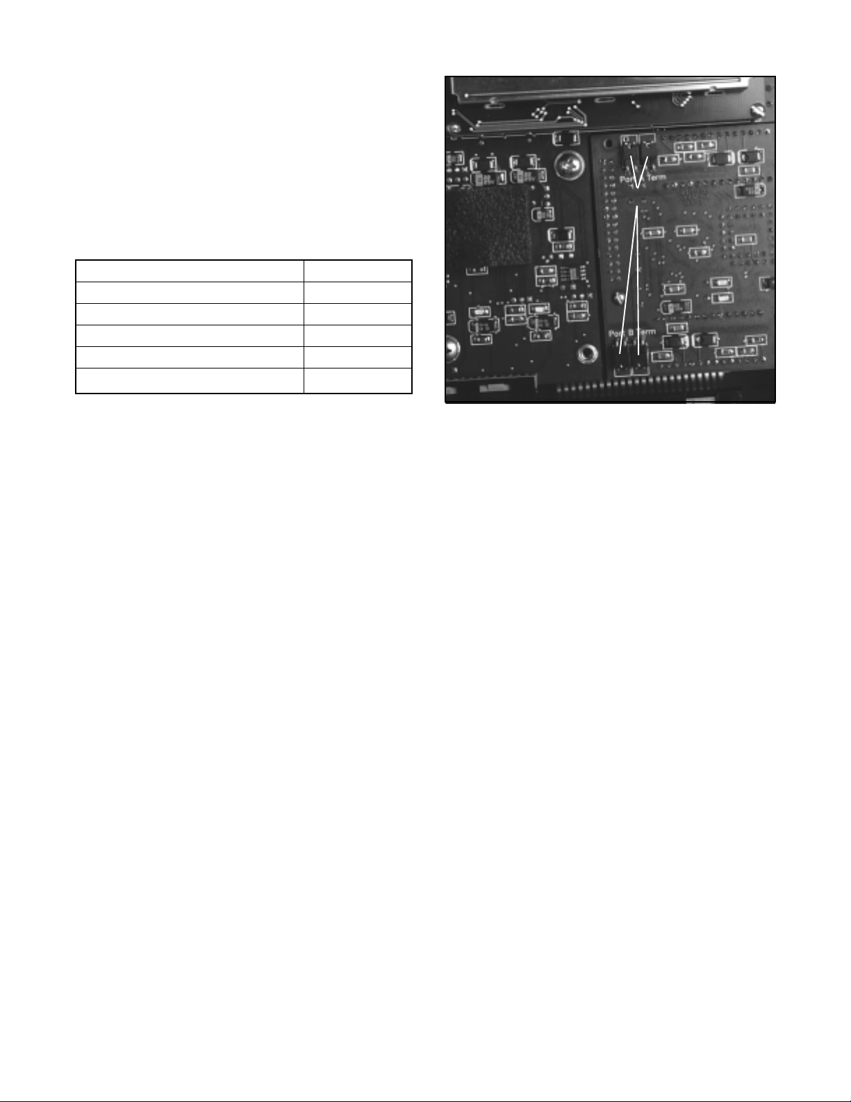
Figure 5: Termination Jumpers and
Personality Module
Selecting Proper RS-485 Termination
Resistor Setting
A termination resistor must be installed on the two most
remote devices on the network, counting the host
computer as any other device.
(For example, a single StarPac II / Logix 2000 unit and
the RS-485 driver in the host computer would each
require the termination resistor to be installed. If four
units were on the network with a host computer, decide
which of the two devices have the most combined cable
length between them. These two devices should have
the termination resistors installed. The termination
resistors should be disabled in the devices not considered to be the most remote using the instructions in the
next section. Using more than two termination resistors
in a network can cause the RS-485 communications to
operate erratically or fail.)
To enable 120 ohms termination, insert both jumpers
for A and B channels. To disable termination, remove
both jumpers from each channel as shown in
Figure 5.
SYSTEM MAINTENANCE
Valtek recommends that the StarPac II / Logix 2000
system calibration be checked every six months. If,
after checking the unit, a component is determined to
be defective, the following section will help with the
component replacement.
The following items may be needed to install, start up
and calibrate the unit's electronics.
42-6
Flowserve Corporation, Valtek Control Products, Tel. USA 801 489 8611

• Power supply: 24 VDC, 300 mA
• Digital volt meter with 4 - 20 mA range
• Air supply: 50 psig minimum, 80-100 psig preferred
• Gauges or the ability to accurately determine pro-
cess pressures and valve air supply pressures
• 4 - 20 mA command source
• Thermocouple calibrator or simulator with 0 to 500°
Celsius range
8. Turn on the air supply to the valve and check for
leaks in the reattached actuator tubing lines.
9. Turn on power to the unit. Check the system
calibration and perform a Valve Stroke Calibration
to reset the position feedback. Refer to the Calibration section of the StarPac II / Logix 2000 manual.
StarPac II / Logix 2000 Positioner
Overview
Mechanical Subsystem Maintenance
Refer to the appropriate Valtek Installation, Operation &
Maintenance (IOM) instructions for details on repair and
maintenance of the control valve actuator components.
Please refer to the manufacturers’ manuals for maintenance and operation instructions for non-pneumatic
actuators, e.g., electric or electro-hydraulic actuators.
WARNING: The process line must be depressurized
and drained of process fluid and decontaminated
prior to working on internal valve components. Failure to do so may cause serious injury to personnel.
1. Depressurize the line, decontaminate the valve (if
needed) and shut off the air supply to the valve
positioner.
2. Disconnect the actuator air tubes from the unit.
3. Disconnect the two mounting bolts that attach the
StarPac II / Logix 2000 system bracket.
4. Disconnect the follower arm from the unit base.
This is done by removing the follower arm nut and
washer and pulling the arm off the shaft. Notice that
this shaft connection is keyed and that the shafts
are slightly spring loaded.
5. The actuator subassembly is now isolated and is
removed by loosening the bonnet bolts and lifting
the actuator away from the body.
The tubing holds the StarPac II / Logix 2000 base in
place, eliminating the need to disconnect wiring or
air connections.
6. Standard valve maintenance may now be done on
the actuator or valve body components. Refer to
the Valtek IOM instructions for details on such
things as trim or packing replacement. If you have
to replace the trim, use the same trim number and
characteristic as the original trim so the flow calculations are not affected. If a trim size change is
needed, contact your Valtek representative to find
out about flow characterization options.
7. Reassemble the system by reversing the above
steps. Be sure to follow the procedures outlined in
the Valtek IOM instructions for valve reassembly.
When reconnecting the follower arm, make sure
that the arm fits correctly on the keyed shaft and has
a positive spring action.
The StarPac II / Logix 2000 is double-acting, capable of
supplying air to either side of the actuator piston while
exhausting the other side to the atmosphere. Also, the
positioner can be mounted on either Valtek linear or
rotary actuators without modification to the actuator.
The positioner is pending non-incendive for class I,
division II, groups A, B, C, and D; class II, groups E,
F, and G. Since the positioner is insensitive to supply
pressure changes and can handle supply pressures
from 30 to 150 psig, a supply regulator is usually not
required; however, an air filter is required due to the
close tolerances of the spool assembly.
NOTE: The air supply should conform to ISA
Standard S7.3 (a dew point at least 18° F below
ambient temperature, particle size below 5 microns,
oil content not to exceed 1 part per million).
Positioner Operation
The StarPac II / Logix 2000 Positioner is an electric
feedback instrument. Figure 6 shows a StarPac II
installed on a double-acting actuator for air-to-open
action. Positioning is based on a balance of two signals:
one proportional to the modulator input signal and the
other proportional to the stem position.
The supply pressure for the positioner modulator is
tapped off the main supply and is filtered as it passes
through a field-replaceable, coalescing filter element in
the module. Next it passes through an internal pressure
regulator that regulates it to approximately 22 psig. The
air then goes through an orifice that restricts the flow
and air consumption (refer to Figure 6).
The air is further controlled to 6-12 psig using a springdiaphragm flapper that is attracted by an electromagnet
to a nozzle. A temperature compensated hall effect
sensor mounted on a circuit board senses the spool
valve position. The hall effect sensor and circuitry
create a feedback loop, which determines how much
current to send to the electromagnet for a desired spool
valve position. The electromagnet in the feedback loop
varies the nozzle-flapper spacing, which regulates the
output pressure to 6-12 psig proportional to the command input signal.
When these opposing signals are equal, the system will
be in equilibrium and the stem will be in the position
called for by the command signal. If these opposing
Flowserve Corporation, Valtek Control Products, Tel. USA 801 489 8611
42-7
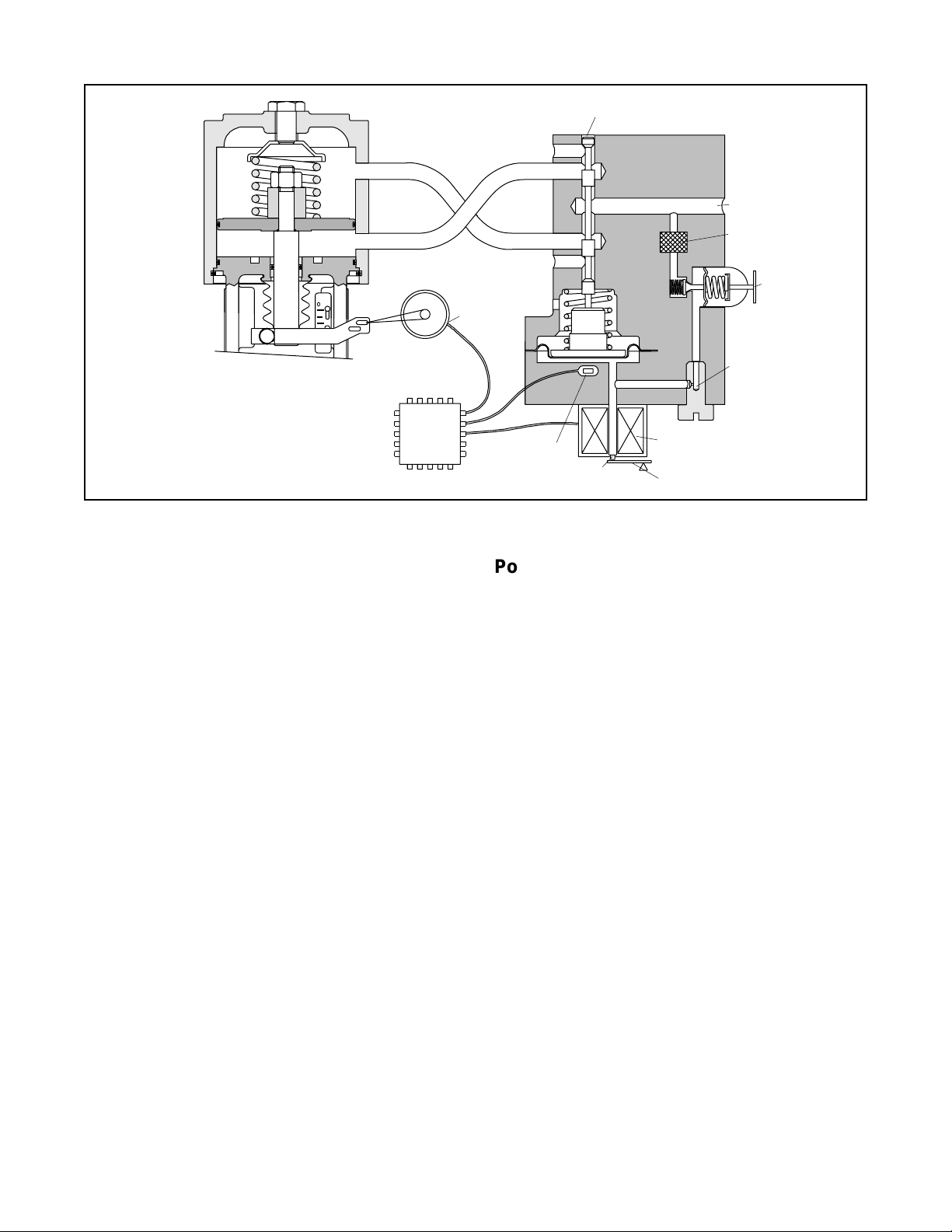
Exhaust
Output 1
Pilot Valve Spool
Air Supply
OO
Air-to-open
Configuration
Digital
Position
Algorithm
Figure 6: Positioner Diagram
signals are not equal, the spool valve will move up (or
down) and, by means of the modulator, will change the
output pressures and flow rate. This will cause the
piston to move until the signal of the feedback sensor
equalizes with the command signal.
The detailed sequence of positioner operations are as
follows: An increase in the command signal forces the
modulator signal capsule and spool valve upward. This
motion of the modulator also pushes the pilot valve
spool upward from its equilibrium position. This opens
the pilot valve ports, supplying air to port one and
exhausting air from port two. This causes the actuator
piston to move upward.
This upward motion of the piston is transmitted back to
the positioner through the feedback linkage and hallpot
sensor signal changing proportionally to the valve position. The piston continues to stroke upward until the
signal of the feedback sensor increases sufficiently to
counter the signal being sent to the modulator. At this
point, the spool is at its equilibrium position as the
pressures in the cylinder stabilize and the air flow to the
actuator decreases.
After the piston has reached the required position, the
feedback signal will equal the spool position generated
in the modulator capsule. The computer will then make
small null adjustments to fine-tune the desired position
and compensate for changes in dynamic loading.
A decrease in the command signal reverses the described actions causing a proportional downward movement of the actuator piston and stem.
Output 2
Exhaust
Stem Position
Sensor
Spool Position
Sensor
Nozzle
Electromagnetic Coil
Flapper
Filter
Regulator
Orifice
Position Feedback System
The position feedback linkage of the StarPac II / Logix
2000 system is a critical part of the system. This linkage
is also used in the StarPac II to calculate the valve’s C
for a given stroke for flow measurement. This linkage
should be lubricated and checked periodically for tight,
smooth operation. The follower arm should operate
smoothly with no binding and have a positive spring
loading on the arm. Inspect the follower arm pin for
excess wear and replace if needed. The take-off arm
attached to the stem clamp must be firmly secured to
the stem clamp and perpendicular to the actuator stem.
If this takeoff arm is canted or misaligned, problems
may occur with positioner calibration and the position
reading on the unit may go out of range.
On rotary actuators, make sure the adjustment linkage
locknut is tight and has no excessive play in the ball
joints. The rotary shaft clamp must be tight and should
not freely rotate on the shaft.
Pressure Sensor Replacement
Standard StarPac II pressure sensors are typically installed directly into the control valve body. Before they
can be removed, the process line must be depressurized
and drained of all fluids and the valve decontaminated.
To replace a pressure sensor, refer to Figure 7 then
proceed as follows.
WARNING: The process line must be depressurized
and drained of process fluid, and decontaminated
prior to working on internal valve components. Failure
to do so may cause serious injury to personnel.
V
42-8
Flowserve Corporation, Valtek Control Products, Tel. USA 801 489 8611
 Loading...