


Digital Positioner 3200MD
LGENIM0059-09 12/13
USER INSTRUCTIONS
Installation
Operation
Maintenance
Safety Manual

User instructions - Digital Positioner 3200MD LGENIM0059-08 10/13
Contents
1 |
Terms Concerning Safety |
3 |
|
|
|
|
|
2 |
General Information |
3 |
|
|
|
|
|
|
3.1 |
Unpacking |
3 |
|
|
|
|
|
3.2 |
Storage |
3 |
|
|
|
|
|
3.3 |
Pre-installation Inspection |
3 |
|
|
|
|
4 |
Logix 3200MD |
|
|
|
Positioner Overview |
4 |
|
|
|
|
|
|
4.1 |
Specifications |
4 |
|
|
|
|
|
4.2 |
Positioner Operation |
6 |
|
|
|
|
|
4.3 |
Detailed Sequence |
|
|
|
of Positioner Operations |
7 |
|
|
|
|
5 |
Mounting and Installation |
8 |
|
|
|
|
|
|
5.1 |
Mounting to Valtek Linear |
|
|
|
Mark One Valves |
8 |
|
|
|
|
|
5.2 |
Mounting to Standard |
|
|
|
Valtek Rotary Valves |
9 |
|
|
|
|
|
5.3 |
Optional Valtek Rotary |
|
|
|
Mounting Procedure |
10 |
|
|
|
|
|
5.4 |
NAMUR Rotary Mounting |
11 |
|
|
|
|
|
5.5 |
Tubing Positioner to Actuator |
11 |
|
|
||
6 Wiring and Grounding Guidelines |
12 |
||
|
|
|
|
|
6.1 |
4-20 mA Command Input Wiring |
12 |
|
|
|
|
|
6.2 |
Grounding Screw |
12 |
|
|
|
|
|
6.3 |
Compliance Voltage |
12 |
|
|
|
|
|
6.4 |
Cable Requirements |
13 |
|
|
|
|
|
6.5 |
Intrinsically Safe Barriers |
14 |
|
|
|
|
7 |
Startup |
14 |
|
|
|
|
|
|
7.1 |
Logix 3200MD Local Interface Operation |
14 |
|
7.2 |
Initial DIP Switch Settings |
14 |
|
|
|
|
|
7.3 |
Operation of Configuration |
|
|
|
DIP Switch Settings |
14 |
|
|
|
|
|
7.4 |
Setup of the Cal Dip-Switch for the Quick Calibration |
|
|
|
operating mode. |
16 |
|
|
|
|
|
7.5 |
QUICK-CAL Operation |
16 |
|
|
|
|
|
7.6 |
Local Control of Valve Position |
17 |
|
|
|
|
|
7.7 |
Factory Reset |
17 |
|
|
|
|
|
7.8 |
Command Reset |
17 |
|
|
|
|
|
7.9 |
Version number checking |
17 |
|
|
|
|
|
7.10 |
Logix 3200MD Status Condition |
17 |
|
7.11 |
ValveSight Configuration and Diagnostic Software and |
|
|
|
HART 375 Handheld Communicator |
17 |
|
|
|
|
8 |
Maintenance and Repair |
21 |
|
|
|
|
|
|
8.1 |
Driver Module Assembly |
21 |
|
|
|
|
|
|
8.2 |
Regulator |
23 |
|
|
8.3 |
Checking or Setting Internal Regulator Pressure |
23 |
|
|
|
|
|
|
|
8.4 |
Spool Valve |
24 |
|
|
|
|
|
|
|
8.5 |
Spool Valve Cover |
24 |
|
|
8.6 |
Stem Position Sensor |
25 |
|
|
|
|
|
|
|
8.7 |
Main PCB Assembly |
26 |
|
|
|
|
|
|
|
8.8 |
Pressure Sensor Board |
26 |
|
|
8.9 |
Customer Interface Board |
27 |
|
|
|
||
|
9 |
Optional Hardware |
28 |
|
|
|
|
|
|
|
|
9.1 |
Vented Design |
28 |
|
|
9.2 |
HART Modem |
28 |
|
|
|
|
|
|
|
9.3 |
4-20 mA Analog Output Board |
29 |
|
|
|
||
|
10 |
Requirements for Safety Integrity |
30 |
|
|
|
10.1 |
Fail Safe State |
30 |
|
|
|
|
|
|
|
10.2 |
Safety Function |
30 |
|
|
|
|
|
|
|
10.3 |
Fail Safe State Response Time |
30 |
|
|
10.4 |
Diagnostic Annunciation and Response Time |
30 |
|
|
|
|
|
|
|
10.5 |
Maximum Achievable SIL |
31 |
|
|
|
|
|
|
|
10.6 |
Model Selection and Specification of Flowserve 3200MD |
|
|
|
|
Positioner |
31 |
|
|
|
|
|
|
|
10.7 |
Installation |
31 |
|
|
|
|
|
|
|
10.8 |
Firmware Update |
31 |
|
|
10.9 |
Required Configuration Settings |
31 |
|
|
|
|
|
|
|
10.10 Reliability Data |
31 |
|
|
|
|
|
|
|
|
10.11 Lifetime Limits |
32 |
|
|
|
10.12 Proof Testing |
32 |
|
|
|
|
|
|
|
|
|
Steps for Proof Test |
32 |
|
|
|
|
|
|
|
10.13 Maintenance |
32 |
|
|
|
10.14 Repair and Replacement |
32 |
|
|
|
|
|
|
|
|
10.15 Training Requirements |
32 |
|
|
|
|
||
|
11 |
Parts List |
34 |
|
12 |
Logix 3200MD Spare Parts Kits |
35 |
||
|
|
|
||
13 |
Logix 3200MD Mounting Kits |
35 |
||
|
|
|
|
|
|
|
13.1 |
Valtek Mounting Kits |
35 |
|
|
13.2 |
Logix O.E.M. Mounting Kits |
36 |
|
|
|
|
|
|
|
13.3 |
NAMUR Accessory Mounting Kit |
|
|
|
|
Part Numbers |
36 |
|
|
|
||
|
15 |
How to Order |
38 |
|
|
|
|
||
16 |
Troubleshooting |
39 |
||
|
|
|
|
|
|
|
|
|
|
2

1 Terms Concerning Safety
The safety terms DANGER, WARNING, CAUTION and NOTE are used in these instructions to highlight particular dangers and/ or to provide additional information on aspects that may not be readily apparent.
DANGER: Indicates that death, severe personal injury and/or substantial property damage will occur if proper precautions are not taken.
WARNING: Indicates that death, severe personal injury and/or substantial property damage can occur if proper precautions are not taken.
CAUTION: Indicates that minor personal injury and/or property damage can occur if proper precautions are not taken.
! NOTE: indicates and provides additional technical information, which may not be very obvious even to qualified personnel. Compliance with other, not particularly emphasized notes, with regard to transport, assembly, operation and maintenance and with regard to technical documentation (e.g., in the operating instruction, product documentation or on the product itself) is essential, in order to avoid faults, which in themselves might directly or indirectly cause severe personal injury or property damage.
2 General Information
The following instructions are designed to assist in unpacking, installing and performing maintenance as required on Valtek® Logix® 3200MD digital positioners. Series 3000 is the term used for all
the positioners herein; however, specific numbers indicate features specific to model (i.e., Logix 3200 indicates that the positioner has HART® protocol). See Logix 3200MD Model Number table in this manual for a breakdown of specific model numbers. Product users and maintenance personnel should thoroughly review this bulletin prior to installing, operating, or performing any maintenance on the valve.
Separate Valtek Flow Control Products Installation, Operation, Maintenance instructions cover the valve (such as IOM 1 or IOM 27) and actuator (such as IOM 2 or IOM 31) portions of the system and other accessories. Refer to the appropriate instructions when this information is needed.
To avoid possible injury to personnel or damage to valve parts, WARNING and CAUTION notes must be strictly followed. Modifying this product, substituting non-factory parts or using maintenance procedures other than outlined could drastically affect performance and be hazardous to personnel and equipment, and may void existing warranties.
User Instructions - Digital Positioner 3200MD LGENIM0059-09 12/13
WARNING: Standard industry safety practices must be adhered to when working on this or any process control product. Specifically, personal protective and lifting devices must be used as warranted.
WARNING: Substitution of components may impair intrinsic safety.
3 Unpacking and Storage
3.1Unpacking
1.While unpacking the Logix 3200MD positioner, check the packing list against the materials received. Lists describing the system and accessories are included in each shipping container.
2.When lifting the system from the shipping container, position lifting straps to avoid damage to mounted accessories. Systems with valves up to six inches may be lifted by actuator lifting ring. On larger systems, lift unit using lifting straps or hooks through the yoke legs and outer end of body.
WARNING: When lifting a valve/actuator assembly with lifting straps, be aware the center of gravity may be above the lifting point. Therefore, support must be given to prevent the valve/actuator from rotating. Failure to do so can cause serious injury to personnel or damage to nearby equipment.
3.In the event of shipping damage, contact the shipper immediately.
4.Should any problems arise, contact a Flowserve Flow Control Division representative.
3.2Storage
Control valve packages (a control valve and its instrumentation) can be safely stored in an enclosed building that affords environmental protection; heating is not required. Control valve packages must be stored on suitable skids, not directly on the floor. The storage location must also be free from flooding, dust, dirt, etc.
3.3Pre-installation Inspection
If a valve control package has been stored for more than one year, inspect one actuator by disassembling it per the appropriate Installation, Operation, and Maintenance Instructions (IOM) prior to valve installation. If O-rings are out-of-round, deteriorated, or both, they must be replaced and the actuator rebuilt. All actuators must then be disassembled and inspected. If the actuator O-rings are replaced, complete the following steps:
1. Replace the pressure-balance plug O-rings.
3

2.Inspect the solenoid and positioner soft goods and replace as necessary.
4 Logix 3200MD
Positioner Overview
The Logix 3200MD digital positioner is a two-wire 4-20 mA input digital valve positioner. The positioner is configurable through the local user interface. The Logix 3200MD utilizes the HART protocol to allow twoway remote communications with the positioner. The Logix 3200MD positioner can control both doubleand single-acting actuators with linear or rotary mountings. The positioner is completely powered by the 4-20 mA input signal. Start up current must be at least 3.6 mA without AO card or 3.85 mA with AO card.
4.1Specifications
Table I: Electrical Specifications
Power Supply |
Two-wire, 4-20 mA |
|
10.0 to 30.0 VDC |
||
|
||
|
|
|
Compliance Voltage |
10.0 VDC @ 20 mA |
|
|
|
|
Effective Resistance |
495 @ 20 mA Typical |
|
Add 20 when HART communication active |
||
|
||
|
|
|
Communications |
HART Protocol |
|
|
|
|
Minimum Operating |
3.6 mA without AO board |
|
Current |
3.85 mA with AO board |
|
|
|
|
Maximum Voltage |
30.0 VDC |
|
|
|
Table II: ValveSight Suite Software Specifications
|
Minimum Pentium processor running Windows 95, 98, |
|
Computer |
NT, 2000, XP, 32 MB total memory (64 MB recom- |
|
mended), 30 MB available hard disk space, CD-ROM |
||
|
||
|
drive |
|
|
|
|
Ports |
1 minimum available with 8 maximum possible. (Can |
|
|
also communicate via PCMCIA and USB connections) |
|
|
|
|
HART Modem |
RS-232/PCMCIA card/USB |
|
|
|
|
HART Filter |
May be required in conjunction with some DCS |
|
hardware |
||
|
||
|
|
|
HART MUX |
MTL 4840/ELCON 2700 |
|
|
|
User Instructions - Digital Positioner 3200MD LGENIM0059-09 12/13
Table III: Environmental Conditions
Operating Temperature Range |
Standard |
-40° to 176°F |
|
|
|||
(-40° to 80°C) |
|||
|
|
||
|
|
|
|
Transport and Storage |
-40° to 176°F (-40° to 80°C) |
||
Temperature Range |
|||
|
|
||
|
|
||
Operating Humidity |
0 - 100% non-condensing |
||
|
|
|
|
! NOTE: The air supply must conform to ISA Standard ISA 7.0.01 (a dew point at least 18 degrees Fahrenheit below ambient temperature, particle size below five microns—one micron recommended—and oil content not to exceed one part per million).
Table IV: Physical Specifications
Housing Material |
Cast, powder-painted aluminum, stainless steel |
|
|
|
|
Soft Goods |
Buna-N / Florosilicone |
|
|
|
|
Weight |
8.3 pounds (3.9 kg) aluminum |
|
20.5 pounds (9.3 kg) stainless steel |
||
|
||
|
|
Table V: Positioner Specifications
Deadband |
<0.1% full scale |
|
|
Repeatability |
<0.05% full scale |
|
|
Linearity |
<0.5% (rotary), <0.8%, (sliding stem) full scale |
|
|
Air Consumption |
<0.3 SCFM (0.5 Nm3/hr) @ 60 psi (4 barg) |
Air Capacity |
12 SCFM @ 60 psi (4 barg) (0.27 Cv) |
|
|
Table VI: 4 to 20 mA Analog Output Specifications
Potential Range of Rotation |
40° - 95° |
|
|
Power Supply Range |
12.5 to 40 VDC, (24 VDC typical) |
|
|
Maximum Load Resistance (ohms) |
(Supply voltage - 12.5) / 0.02 |
|
|
Current Signal Output |
4-20 mA |
|
|
Linearity |
1.0% F.S. |
|
|
Repeatability |
0.25% F.S. |
|
|
Hysteresis |
≤ .2% F.S. |
|
|
Operating Temperature |
-40° to 176°F, -40° to 80°C |
|
|
4

|
|
|
User Instructions - Digital Positioner 3200MD LGENIM0059-09 12/13 |
|||
Table VII: Hazardous Area Certifications |
|
|
|
|
||
|
|
|
|
|
|
|
|
|
|
|
North America (FM/CSA) |
|
|
|
Flame Proof |
|
Explosion Proof |
|
|
|
|
SIRA 03ATEX1387 |
|
Class I, Div 1, Groups B,C,D |
|
|
|
|
II 2 GD |
|
DIP Class II, III, Div 1 Groups E,F,G |
|
|
|
|
Ex d IIB+H2 T5 IP65 |
|
Class I, Zone 1, Ex d IIB+H2 (CSA Only) |
|
|
|
|
Ex tD A21 IP65 T95˚C (Ta =-40°C to +80°C) |
T5 Tamb = -40˚C ≤ Ta ≤ +80˚C (CSA Only) |
|
|
||
|
T5 (Ta = -40˚C to +80C |
|
T6 Tamb = -40˚C ≤ Ta ≤ +60˚C |
|
|
|
|
|
|
Type 4X |
|
|
|
|
|
|
|
|
|
|
|
Intrinsically Safe |
|
Intrinsically Safe |
|
|
|
|
SIRA 03ATEX2299X |
|
Class I,II, III, Div 1, Groups A,B,C,D,E,F,G |
|
|
|
|
II 1 GD |
|
Class I, Zone 0, AExia IIC (FM Only) |
|
|
|
|
Ex ia IIC |
Ex iaD 20 T95˚C |
T4 Tamb = -50˚C ≤ Ta ≤ +85˚C |
|
|
|
|
T4 (Ta = -52˚C to +85˚C) |
(Ta = -52˚C to +80˚C) |
T5 Tamb = -50˚C ≤ Ta ≤ +55˚C |
|
|
|
|
T5 (Ta = -52˚C to +55˚C) |
|
Type 4X |
|
|
|
|
Entity Parameters |
|
Entity Parameters |
|
|
|
|
Ui = 30V |
|
Ui = 30V |
|
|
|
|
Ii = 100mA |
|
Ii = 100mA |
|
|
|
|
Pi = 800mW |
|
Pi = 800mW |
|
|
|
|
Ci = 30nF Co = 36nF |
|
Ci = 30nF |
|
|
|
|
Li = 0 |
|
Li = 0 |
|
|
|
|
|
|
|
|
|
|
|
Non-Incendive |
|
Non-Incendive |
|
|
|
|
SIRA 08ATEX4006 |
|
|
|
|
|
|
|
Class I, Div 2, Groups A,B,C,D |
|
|
||
|
II 3 GD |
|
|
|
||
|
|
T4 Tamb = -50˚C ≤ Ta ≤ +85˚C |
|
|
||
|
Ex nL nA IIC |
|
|
|
||
|
|
T5 Tamb = -50˚C ≤ Ta ≤ +55˚C |
|
|
||
|
Ex tD A22 T95˚C (Ta = -52°C to +80°C) |
|
|
|||
|
Type 4X |
|
|
|
||
|
T4 (Ta = -52˚C to +85˚C) |
|
|
|
|
|
|
|
Barriers Not Required |
|
|
|
|
|
T5 (Ta = -52˚C to +55˚C) |
|
|
|
|
|
|
|
|
|
|
|
|
|
|
|
|
|
|
|
|
|
IECEx |
|
InMetro |
||
|
Explosion Proof |
|
Explosion Proof |
|
|
|
|
IECEx SIR 04.0023X |
|
TÜV 11.0070 |
|
|
|
|
Ex d IIB+H2 T5 |
|
Ex d IIB+H2 T5 Gb IP65 |
|
|
|
|
Ta = -40˚C to +55˚C |
|
Ta = -40˚C -Ta - +80˚C |
|
|
|
|
|
|
|
|
|
|
|
Intrinsically Safe |
|
Instrinsically Safe |
|
|
|
|
IECEx FMG 05.0003X |
|
TÜV 11.0071X |
|
|
|
|
Ex ia IIC |
Ex iaD 20 T95˚C |
Ex ia IIC Ga IP65 |
Ex ia IIIC T95˚C Da IP65 |
|
|
|
T4 Ta = -40˚C to +85˚C |
Ta = -40C to +80˚C |
T4 Ta = -40˚C-Ta- +85˚C |
Ta = -40˚C-Ta- +85˚C |
|
|
|
T5 Ta = -40˚C to +55˚C |
|
T5 Ta = -40˚C-Ta- +55˚C |
|
|
|
|
Entity Parameters |
|
Entity Parameters |
|
|
|
|
Ui = 30V |
|
Ui = 30Vcc |
|
|
|
|
Ii = 100mA |
|
Ii = 100mA |
|
|
|
|
Pi = 800mW |
|
Pi= 800mW |
|
|
|
|
Ci = 30nF |
|
Ci = 30nF |
|
|
|
|
Li = 0 |
|
Li = 0 |
|
|
|
|
|
|
|
|
|
|
|
|
KOSHA |
|
Gost |
||
|
Explosion Proof |
|
|
|
|
|
|
10-AV4BO-0560X |
|
|
|
|
|
|
Ex d IIB+H2 T5 |
|
|
|
|
|
|
T5 Ta = -20°C to +50°C |
|
|
|
|
|
|
|
|
|
|
|
|
Special Conditions for Safe Use:
•The equipment must be installed in such a manner as to minimize the risk of impact or friction with other metal surfaces.
•To avoid possibility of static discharge clean only with a damp Cloth
•In order to maintain the explosion proof certifications do not remove or loosen covers while circuits are live.
•For Intrinsically Safe installations the positioner must be connected to suitably rated intrinsically safe equipment, and must be installed in accordance with intrinsically safe installation standards.
•Substitution of components may impair Intrinsic Safety.
5

4.2Positioner Operation
The Logix 3200MD positioner is an electric feedback instrument. Figure 1 shows a Logix 3200MD positioner installed on a doubleacting linear actuator for air-to-open action.
The Logix 3200MD receives power from the two-wire, 4-20 mA input signal. However, since this positioner utilizes HART communications, two sources can be used for the command signal:
Analog and Digital. In Analog source, the 4-20 mA signal is used for the command source. In Digital source, the level of the input 4-20 mA signal is ignored and a digital signal, sent via HART, is used as the command source. The command source can be accessed with ValveSight software, the HART 375 communicator, or other host software.
Whether in Analog or Digital Source, 0% is always defined as the valve closed position and 100% is always defined as the valve open position. In Analog Source, the 4-20 mA signal is converted to a percentage. During loop calibration, the signals corresponding to 0% and 100% are defined. The input signal in percent passes through a characterization/limits modifier block. The positioner no longer uses CAMs or other mechanical means to characterize the output of the positioner. This function is done in software, which allows for in-the-field customer adjustment. The positioner has three basic modes: Linear, Equal Percent (=%) and Custom characterization. In Linear mode, the input signal is passed straight through to
User Instructions - Digital Positioner 3200MD LGENIM0059-09 12/13
the control algorithm in a 1:1 transfer. In Equal Percent (=%) mode, the input signal is mapped to a standard 30:1 rangeability =% curve. If Custom characterization is enabled, the input signal is mapped to either a default =% output curve or a custom, user-defined 21-point output curve. The custom user-defined 21-point output curve is defined using a handheld or ValveSight software. In addition, two user-defined features, Soft Limits and MPC (Minimum Position Cutoff), may affect the final input signal. The actual command being used to position the stem, after any characterization or user limits have been evaluated, is called the Control Command.
The Logix 3200MD uses a two-stage, stem-positioning algorithm. The two stages consist of an inner-loop, spool control and an outerloop, stem position control. Referring again to Figure 1, a stem position sensor provides a measurement of the stem movement. The Control Command is compared against the Stem Position. If any deviation exists, the control algorithm sends a signal to the inner-loop control to move the spool up or down, depending upon the deviation. The inner-loop then quickly adjusts the spool position. The actuator pressures change and the stem begins to move. The stem movement reduces the deviation between Control Command and Stem Position. This process continues until the deviation goes to zero.
The inner-loop controls the position of the spool valve by means of a driver module. The driver module consists of a temperature-com- pensated hall effect sensor and a piezo valve pressure modulator.
Figure 1: Logix 3200MD Digital Positioner Schematic (air-to-open configuration)
HART Terminals |
Analog Output Signal Main PCB |
|
|
|
|
|
|
Digital Position Algorithm |
|
|
Command |
|
|
|
|
|
Input Signal |
|
|
|
|
|
Spool Valve |
|
Pressure |
Air Supply |
|
|
|
|
||
|
|
|
|
|
|
|
|
Exhaust |
Flame |
Sensor Board |
|
|
|
|
|
||
|
|
|
Arrestor |
|
|
|
|
Output 1 |
|
|
|
|
|
|
|
|
Flame |
|
|
|
|
|
Arrestor |
|
|
Output 2 |
|
|
|
|
|
|
|
|
LED |
|
|
|
|
|
Display |
|
|
|
|
|
Filter |
O |
|
Flame |
|
|
|
|
|
Arrestor |
|
|
|
|
Stem |
Hall Effect |
|
|
Regulator |
|
Position |
|
|
||
|
Sensor |
|
|
|
|
|
Sensor |
|
|
|
|
|
|
|
|
|
|
6 |
|
Piezo Valve |
|
|
|
|
|
|
|
|
User Instructions - Digital Positioner 3200MD LGENIM0059-09 12/13
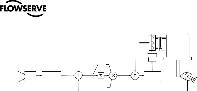
Figure 2: System Positioning Algorithm
|
|
|
|
|
|
|
|
|
|
Air |
|
|
|
|
|
|
|
|
|
|
|
Supply |
Tubed |
|
|
|
|
|
|
|
|
|
|
|
|
|
|
|
|
|
|
|
|
|
|
|
ATO |
|
|
|
|
|
|
|
Control |
|
|
|
Sensor |
|
|
|
|
|
|
|
Algorithm |
|
|
|
|
|
|
|
|
|
|
|
|
|
|
|
|
|
|
|
|
|
|
|
Pmax |
|
Inner-Loop |
|
|
|
|
|
|
|
|
|
|
Output |
|
|
|
|
|
|
|
|
|
|
Pmin |
|
|
|
Piezo |
|
|
|
|
|
|
|
Gmult |
|
|
|
|
4-20 |
Input |
|
|
|
|
|
|
|
|
|
Valve |
|
|
|
|
|
|
|
|
|
Voltage |
||
mA |
Signal |
|
|
|
|
|
|
|
D/A |
|
|
(Analog |
|
Linear Mode |
|
|
|
|
|
|
- |
Inner |
|
Mode) |
Analog |
CONTROL |
|
|
Deviation |
|
+ |
Output |
|||
Characterization |
|
|
|
||||||||
|
COMMAND |
+ |
|
|
I |
+ |
Percentage |
+ |
Loop |
||
|
Digital |
Soft Limits |
|
- |
|
|
+ |
|
Spool |
||
Command |
|
|
|
|
Integration |
|
|
Control |
|||
|
MPC |
|
|
|
|
|
|
|
|||
In |
|
|
|
|
|
|
Summer |
|
|
|
|
(Digital |
|
|
|
|
|
|
|
|
|
Stem |
|
|
|
|
|
|
|
|
|
|
|
||
Mode) |
|
|
|
|
|
|
Inner |
|
|
|
Position |
|
|
|
|
|
|
|
Loop |
|
|
|
Sensor |
|
|
|
|
|
|
|
Offset |
|
|
|
|
The piezo valve pressure modulator controls the air pressure under a diaphragm by means of a piezo beam bender. The piezo beam deflects in response to an applied voltage from the inner-loop electronics. As the voltage to the piezo valve increases, the piezo beam bends, closing off against a nozzle causing the pressure under
the diaphragm to increase. As the pressure under the diaphragm increases or decreases, the spool valve moves up or down respectively. The hall effect sensor transmits the position of the spool back to the inner-loop electronics for control purposes.
4.3Detailed Sequence
of Positioner Operations
A more detailed example explains the control function. Assume the unit is configured as follows:
•Unit is in Analog command source.
•Custom characterization is disabled (therefore characterization is
Linear).
•No soft limits enabled. No MPC set.
•Valve has zero deviation with a present input signal of 12 mA.
•Loop calibration: 4 mA = 0% command, 20 mA = 100% command.
•Actuator is tubed and positioner is configured air-to-open.
Given these conditions, 12 mA represents a Command source of 50 percent. Custom characterization is disabled so the Command source is passed 1:1 to the Control Command. Since zero deviation exists, the Stem Position is also at 50 percent. With the stem at the desired position, the spool valve will be at a middle position that balances the pressures above and below the piston in the actuator. This is commonly called the null or balanced spool position.
Assume the input signal changes from 12 mA to 16 mA. The positioner sees this as a Command source of 75 percent. With Linear characterization, the Control Command becomes 75 percent. Deviation is the difference between Control Command and Stem Position : Deviation = 75% - 50% = +25%, where 50 percent is the present
stem position. With this positive deviation, the control algorithm sends a signal to move the spool up from its present position. As the spool moves up, the supply air is applied to the bottom of the actuator and air is exhausted from the top of the actuator. This new pressure differential causes the stem to start moving towards the desired position of 75 percent. As the stem moves, the Deviation begins to decrease. The control algorithm begins to reduce the spool opening. This process continues until the Deviation goes to zero. At this point, the spool will be back in its null or balanced position. Stem movement will stop and the desired stem position is now achieved.
One important parameter has not been discussed to this point: Inner loop offset. Referring to Figure 2, a number called Inner loop offset is added to the output of the control algorithm. In order for the spool to remain in its null or balanced position, the control algorithm must output a non-zero spool command. This is the purpose of the Inner loop offset. The value of this number is equivalent to the signal that must be sent to the spool position control to bring it to a null position with zero deviation. This parameter is important for proper control and is optimized and set automatically during stroke calibration.
7

User Instructions - Digital Positioner 3200MD LGENIM0059-09 12/13
Figure 3: Linear Mark One Control Valve Mounting
Logix 3200IQ
Positioner Bracket
Bolts
Bracket
Locknut
Washer
ollower rm
Positioner
Nut
Nut
Lock Washer
Nut
Follower Pin
Take-off Arm
Bolts
5 Mounting and Installation
5.1Mounting to Valtek Linear Mark One Valves
To mount a Logix 3200MD positioner to a Valtek linear Mark One valve, refer to Figure 3 and proceed as outlined below. The following tools are required:
•9⁄16" open-end wrench (or ½" for spud sizes 2.88 and smaller)
•7⁄16" box wrench
•3⁄8" open-end wrench
1. Remove washer and nut from follower pin assembly. Insert pin into the appropriate hole in follower arm, based on stroke length. The stroke lengths are stamped next to their corresponding holes in the follower arms. Make sure the unthreaded end of the pin is on the stamped side of the arm. Reinstall lock washer and tighten nut to complete follower arm assembly.
2. Slide the double-D slot in the follower arm assembly over the flats on the position feedback shaft in the back of the positioner. Make sure the arm is pointing toward the customer interface side of the positioner. Slide lock washer over the threads on the
shaft and tighten down the nut.
8
Bolts
Stem Clamp
Metal Washers
3.Align the bracket with the three outer mounting holes on the positioner. Fasten with ¼" bolts.
4.Screw one mounting bolt into the hole on the yoke mounting pad nearest the cylinder. Stop when the bolt is approximately 3⁄16" from being flush with mounting pad.
5.Slip the large end of the teardrop shaped mounting hole in the
back of the positioner/bracket assembly over the mounting bolt. Slide the small end of the teardrop under the mounting bolt and align the lower mounting hole.
6.Insert the lower mounting bolt and tighten the bolting.
7.Position the take-off arm mounting slot against the stem clamp mounting pad. Apply Loctite 222 to the take-off arm bolting and insert through washers into stem clamp. Leave bolts loose.
8.Slide the appropriate pin slot of the take-off arm, based on stroke length, over the follower arm pin. The appropriate stroke lengths are stamped by each pin slot.
9.Center the take-off arm on the rolling sleeve of the follower pin.
10.Align the take-off arm with the top plane of the stem clamp and tighten bolting. Torque to 120 in-lb.

User Instructions - Digital Positioner 3200MD LGENIM0059-09 12/13
! NOTE: If mounted properly, the follower arm should be horizontal when the valve is at 50% stroke and should move approximately ±30° from horizontal over the full stroke of the valve. If mounted incorrectly, a stroke calibration error will occur and the indicator lights will blink a RGGY code indicating the position sensor has gone out of range on one end of travel. Reposition the feedback linkage or rotate the position sensor to correct the error.
5.2Mounting to Standard
Valtek Rotary Valves
(See Figure 4)
The standard rotary mounting applies to Valtek valve/actuator assemblies that do not have mounted volume tanks or handwheels. The standard mounting uses a linkage directly coupled to the valve shaft. This linkage has been designed to allow for minimal misalignment between the positioner and the actuator. The tools required for the following procedure are:
•5⁄32" Allen wrench
•½" open-end wrench
•7⁄16" open-end wrench
•3⁄8" socket with extension
•3⁄16" nutdriver
1.Fasten the spline lever adapter to the splined lever using two 6 x ½" self-tapping screws.
2.Slide the take-off arm assembly onto the spline lever adapter shaft. Insert the screw with star washer through the take-off arm and add the second star washer and nut. Tighten nut with socket so arm is lightly snug on the shaft but still able to rotate. This will be tightened after linkage is correctly oriented.
3.Attach follower arm to positioner feedback shaft using the star washer and 10-32 nut.
! NOTE: The arm will point up when feedback shaft is in the free position.
4.Using four ¼-20 x ½" bolts, fasten positioner to universal bracket using appropriate hole pattern (stamped on bracket).
5.Using a ½" end wrench and two 5⁄16-18 x ½" bolts, attach bracket to actuator transfer case pad. Leave these bolts slightly loose until final adjustments are made.
6.Rotate take-off arm so the follower pin will slide into the slot on the take-off arm. Adjust the bracket position as needed noting the engagement of the follower pin and the take-off arm slot.
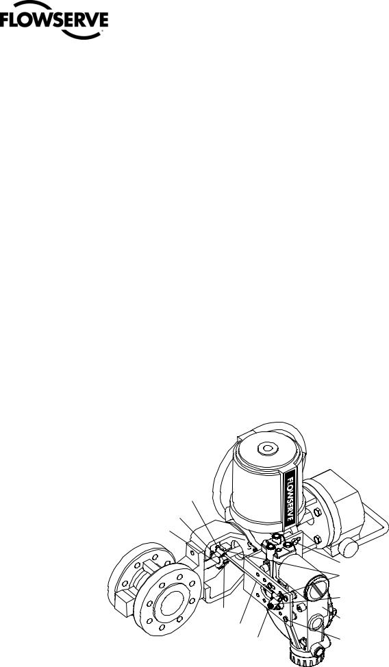
Figure 4: Standard Rotary Mounting
Positioner Bolts ¼-20 (4)*
Bracket Bolts 5/16 -18 (2, not shown)
|
Take-off Arm, Rotary |
|
|
Lock Washer (2) |
|
Logix 3200MD |
10-32 |
Bolt |
Digital Positioner |
10-32 |
Nut |
|
Self-tapping Screws (2) |
|
|
Spline Lever Adapter |
|
|
10-32 |
Nut |
|
Lock Washer |
|
Follower Arm
* Located in appropriate hole pattern as indicated on bracket. (25, 50, 100/200)
9
User Instructions - Digital Positioner 3200MD LGENIM0059-09 12/13
The pin should extend approximately 1⁄16" past the take-off arm. When properly adjusted, securely tighten the bracketing bolts.
Orienting the Take-off Arm for Final Lock Down
1.Tube the Logix 3200MD positioner to the actuator according to the instructions given in Section 5.5, “Tubing Positioner to Actuator.”
2.With supply pressure off, rotate the follower arm in the same direction the shaft would rotate upon a loss of supply pressure. When the mechanical stop of the follower arm (positioner) is reached, rotate back approximately 15 degrees.
3.Hold the take-off arm in place; tighten the screw of the take-off arm.
! NOTE: The take-off arm should be snug enough to hold the follower arm in place but allow movement when pushed.
4.Connect regulated air supply to appropriate port in manifold.
5.Remove main cover and locate DIP switches and QUICK-CAL button.
6.Refer to sticker on main board cover and set DIP switches accordingly. (A more detailed explanation of the DIP switch settings is given in Section 7, “Startup.”)
7.Press the QUICK-CAL button for three to four seconds or until the positioner begins to move. The positioner will now perform a stroke calibration.
8.If the calibration was successful the green LED will blink GGGG or GGGY and the valve will be in control mode. Continue with step 9. If calibration failed, as indicated by a RGGY blink code,
Figure 5: Optional Rotary Mounting
the A/D feedback values were exceeded and the arm must be adjusted away from the positioners limits. Return to step 2 and rotate the arm back approximately 10 degrees.
!NOTE: Remember to remove the air supply before re-adjusting take-off arm.
9.Tighten the nut on the take-off arm. The socket head screw of the take-off arm must be tight, about 40 in-lb.
!NOTE: If the take-off arm slips, the positioner must be recalibrated.
WARNING: Failure to follow this procedure will result in positioner and/or linkage damage. Check air-action and stroke carefully before lockdown of take-off arm to spline lever adapter.
5.3Optional Valtek Rotary
Mounting Procedure
(See Figure 5)
The optional rotary mounting applies to Valtek valve/actuator assemblies that are equipped with mounted volume tanks or handwheels. The optional mounting uses a four-bar linkage coupled to the valve shaft. The following tools are required:
•3⁄8" open-end wrench
•7⁄16" open-end wrench
•½" open-end wrench
Valtek
Locknuts (2)
Tripper
Tripper Clamp
|
Bolts (2) |
|
Tie Rod* |
|
10-32 Nut |
* Tie Rod must be cut to desired length. |
Lock Washer |
Bracket Bolts 5/16-18 (2)
Ball Joint Ends
Follower Arm
Rotate Positioner 90°
Mounting Bolts ¼-20 (4)
10
User Instructions - Digital Positioner 3200MD LGENIM0059-09 12/13
1.Using a ½" open-end wrench and two 5⁄16-18 x ½" bolts, attach bracket to actuator transfer case pads. Leave bracket loose to allow for adjustment.
2.Using four ¼-20 x ½" bolts and a 7⁄16" open-end wrench, fasten positioner to universal bracket, using the four-hole pattern that locates the positioner the farthest from the valve. Rotate positioner 90 degrees from normal so gauges are facing upward.
3.Attach follower arm to positioner feedback shaft, using the star washer and 10-32 nut.
4.Attach tripper and tripper clamp to valve shaft using two ¼-20 bolts and two ¼-20 locknuts. Leave tripper loose on shaft until final adjustment.
5.Thread ball joint linkage end to tripper and tighten (thread locking compound such as Loctite is recommended to prevent back threading). Adjust the length of tie rod so follower arm and tripper rotate parallel to each other (the rod must be cut to the desired length). Connect the other ball joint end to follower arm using a star washer and a 10-32 nut.
6.Tighten bracket and tripper bolting.
7.Check for proper operation, note direction of rotation.
WARNING: If rotating in wrong direction, serious damage will occur to the positioner and/or linkage. Check air action and stroke direction carefully before initiating operation.
5.4NAMUR Rotary Mounting
The Logix 3200MD includes an option for NAMUR Rotary mounting. The NAMUR shaft option provides mounting to standard brackets for valve automation. The NAMUR option is not recommended for high performance valves since the normal alignment tolerances can cause a degradation in valve performance. Care must be taken when mounting the positioner using a NAMUR configuration to prevent damage to the shaft. Mount the positioner and rotate into position using the following table:
Logix 3200 Positioner NAMUR Mounting
Actuator Rotation from |
NAMUR Positioner shaft |
|
FAIL POSITION (as viewed from |
||
preloading instructions |
||
positoner mounting end) |
|
|
|
Insert positioner shaft into |
|
Counter Clockwise |
feedback slot with valve in the |
|
FAIL POSITION and rotate 105° |
||
|
||
|
and bolt into place. |
|
|
|
|
|
Insert positioner shaft into |
|
Clockwise |
feedback slot with valve in FAIL |
|
Position and rotate positioner |
||
|
||
|
CCW 15° and bolt in place |
|
|
|
5.5Tubing Positioner to Actuator
The Logix 3200MD digital positioner is insensitive to supply pressure changes and can handle supply pressures from 30 to 150 psig. A supply regulator is recommended if the customer will be using the diagnostic features of the Logix 3200MD but is not required. In applications where the supply pressure is higher than the maximum actuator pressure rating a supply regulator is required to lower the pressure to the actuator’s maximum rating (not to be confused with operating range). An air filter is highly recommended for all applications where dirty air is a possibility.
! NOTE: The air supply must conform to ISA Standard ISA 7.0.01 (a dew point at least 18°F below ambient temperature, particle size below five microns—one micron recommended—and oil content not to exceed one part per million).
Air-to-open and air-to-close are determined by the actuator tubing, not the software. When air action selection is made during configuration, that selection tells the control which way the actuator has been tubed. The top output port is called Output 1. It should be tubed to the side of the actuator that must receive air to begin the correct action on increasing signal. Verify that tubing is correct prior to a stroke calibration. Proper tubing orientation is critical for the positioner to function correctly and have the proper failure mode. Refer to Figure 5 and follow the instructions below:
Linear Double-acting Actuators
For a linear air-to-open actuator, the Output 1 port of the positioner manifold is tubed to the bottom side of the actuator. The Output 2 port of the positioner manifold is tubed to the top side of the actuator. For a linear air-to-close actuator the above configuration is reversed.
Rotary Double-acting Actuators
For a rotary actuator, the Output 1 port of the positioner manifold is tubed to the bottom side of the actuator. The Output 2 port of the positioner manifold is tubed to the top side of the actuator. This tubing convention is followed regardless of air action. On rotary actuators, the transfer case orientation determines the air action.
Single-acting Actuators
For single-acting actuators, the Output 1 port is always tubed to the pneumatic side of the actuator regardless of air action. The Output 2 port must be plugged.
11
User Instructions - Digital Positioner 3200MD LGENIM0059-09 12/13
6 Wiring and Grounding Guidelines
(See Figure 6)
WARNING: This product has electrical conduit connections in either thread sizes ½" NPT or M20 which appear identical but are not interchangeable. Housings with M20 threads are stamped with the letters M20 above the conduit opening. Forcing dissimilar threads together will damage equipment, cause personal injury and void hazardous location certifications. Conduit fittings must match equipment housing threads before installation. If threads do not match, obtain suitable adapters or contact a Flowserve representative.
6.14-20 mA Command Input Wiring
Verify polarity when making field termination connection. The Logix 3200 is reverse polarity protected. Wire 4-20 mA current source to the input terminal labeled 4-20 mA Input on the user interface board (See Figure 6). Never connect a voltage source directly across the Logix 3200MD terminals. The current must always be limited for 4-20 mA operation. Minimum operating current is 3.6 mA.
The input loop current signal to the Logix 3200MD digital positioner should be in shielded cable. Shields must be tied to a ground at only one end of the cable to provide a place for environmental electrical noise to be removed from the cable. In general, shield wire should be connected at the source.
! NOTE: The Logix 3200MD positioner carries an intrinsically safe barrier rating of 100 mA. Input currents should not exceed 100 mA.
6.2Grounding Screw
The green grounding screw, located inside the termination cap, should be used to provide the unit with an adequate and reliable earth ground reference. This ground should be tied to the same ground as the electrical conduit. Additionally, the electrical conduit should be earth grounded at both ends of its run.
WARNING: The green grounding screw must not be used to terminate signal shield wires.
6.3Compliance Voltage
(See Figure 7)
Output compliance voltage refers to the voltage limit that can be provided by the current source. A current loop system consists of the current source, wiring resistance, barrier resistance (if present), and the Logix 3200MD positioner impedance. The Logix 3200MD digital positioner requires that the current loop system allows for
a 10.0 VDC drop across the positioner at maximum loop current. The 10.0 VDC drop across the Logix 3200MD positioner terminals is generated by the positioner from the 4-20 mA loop current input. The actual voltage at the terminals varies from 9.8 to 10.0 VDC depending on the current mA signal, HART communications, and ambient temperature.
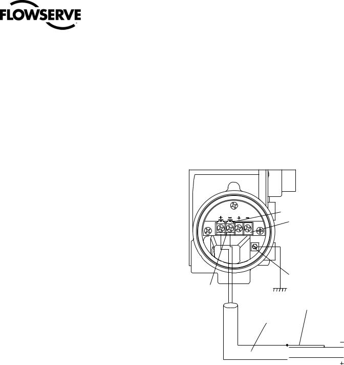
Figure 6: Field Termination
HART |
ANALOG |
HART Terminals |
4-20 mA INPUT |
OUTPUT |
|
|
|
4-20 mA Feedback |
|
|
Terminals (Optional) |
|
|
Housing EARTH |
|
|
Terminal |
Field
Terminators Connect Shield at Source
Ground 4-20 mA Current Source
Shielded Cable
 4-20 mA Current Source
12
 Loading...