


 Loading...
Dell EMC PowerEdge R440
Installation and Service Manual
Regulatory Model: E45S Series
Regulatory Type: E45S001
December 2020
Rev. A11

Notes, cautions, and warnings

 NOTE: A NOTE indicates important information that helps you make better use of your product.
 CAUTION: A CAUTION indicates either potential damage to hardware or loss of data and tells you how to avoid the problem.
 WARNING: A WARNING indicates a potential for property damage, personal injury, or death.
© 2017 - 2020 Dell Inc. or its subsidiaries. All rights reserved. Dell, EMC, and other trademarks are trademarks of Dell Inc. or its subsidiaries. Other trademarks may be trademarks of their respective owners.

Contents
Chapter 1: Dell EMC PowerEdge R440 system overview................................................................. |
7 |
Front view of the system................................................................................................................................................... |
7 |
Left control panel view............................................................................................................................................... |
10 |
Right control panel view............................................................................................................................................. |
13 |
Drive indicator codes................................................................................................................................................... |
14 |
Back view of the system.................................................................................................................................................. |
15 |
NIC indicator codes...................................................................................................................................................... |
17 |
Power supply unit indicator codes........................................................................................................................... |
17 |
LCD panel............................................................................................................................................................................. |
18 |
Viewing Home screen.................................................................................................................................................. |
19 |
Setup menu.................................................................................................................................................................... |
19 |
View menu..................................................................................................................................................................... |
20 |
Locating the Service Tag of your system................................................................................................................... |
20 |
System Label Information................................................................................................................................................ |
21 |
Chapter 2: Initial system setup and configuration........................................................................ |
22 |
Setting up your system.................................................................................................................................................... |
22 |
iDRAC configuration......................................................................................................................................................... |
22 |
Options to set up iDRAC IP address....................................................................................................................... |
22 |
Log in to iDRAC............................................................................................................................................................ |
23 |
Options to install the operating system....................................................................................................................... |
23 |
Methods to download firmware and drivers......................................................................................................... |
23 |
Downloading drivers and firmware.......................................................................................................................... |
24 |
Chapter 3: Installing and removing system components.............................................................. |
25 |
Safety instructions............................................................................................................................................................ |
25 |
Before working inside your system............................................................................................................................... |
26 |
After working inside your system.................................................................................................................................. |
26 |
Recommended tools......................................................................................................................................................... |
26 |
Optional front bezel.......................................................................................................................................................... |
26 |
Removing the front bezel.......................................................................................................................................... |
26 |
Installing the front bezel............................................................................................................................................ |
27 |
System cover...................................................................................................................................................................... |
28 |
Removing the system cover..................................................................................................................................... |
28 |
Installing the system cover....................................................................................................................................... |
29 |
Inside the system.............................................................................................................................................................. |
30 |
Backplane cover................................................................................................................................................................. |
31 |
Removing the backplane cover................................................................................................................................. |
31 |
Installing the backplane cover.................................................................................................................................. |
32 |
Air shroud............................................................................................................................................................................ |
34 |
Removing the air shroud............................................................................................................................................ |
34 |
Installing the air shroud.............................................................................................................................................. |
34 |
Cooling fans........................................................................................................................................................................ |
35 |
Removing the cooling fan.......................................................................................................................................... |
35 |
Contents 3
Installing cooling fan................................................................................................................................................... |
36 |
Intrusion switch.................................................................................................................................................................. |
37 |
Removing the intrusion switch................................................................................................................................. |
37 |
Installing the intrusion switch................................................................................................................................... |
38 |
Drives................................................................................................................................................................................... |
39 |
Removing a drive blank.............................................................................................................................................. |
39 |
Installing a drive blank................................................................................................................................................ |
39 |
Removing a 2.5-inch drive from a 3.5-inch drive adapter................................................................................. |
40 |
Installing a 2.5-inch drive into a 3.5-inch drive adapter..................................................................................... |
41 |
Removing a 3.5-inch drive adapter from a 3.5-inch drive carrier.................................................................... |
41 |
Installing a 3.5-inch drive adapter into the 3.5-inch drive carrier................................................................... |
42 |
Removing a hard drive................................................................................................................................................ |
43 |
Installing a hard drive.................................................................................................................................................. |
44 |
Removing the drive from the drive carrier............................................................................................................ |
45 |
Installing a drive into the drive carrier.................................................................................................................... |
46 |
System memory................................................................................................................................................................. |
46 |
System memory guidelines........................................................................................................................................ |
46 |
General memory module installation guidelines.................................................................................................... |
48 |
Mode-specific guidelines........................................................................................................................................... |
48 |
Removing a memory module..................................................................................................................................... |
51 |
Installing a memory module....................................................................................................................................... |
52 |
Processors and heat sinks............................................................................................................................................... |
53 |
Removing a processor and heat sink module....................................................................................................... |
53 |
Installing a processor and heat sink module.......................................................................................................... |
54 |
Removing the processor from the processor and heat sink module.............................................................. |
55 |
Installing the processor into a processor and heat sink module...................................................................... |
56 |
Internal PERC riser........................................................................................................................................................... |
58 |
Removing the internal PERC riser........................................................................................................................... |
58 |
Installing the internal PERC riser............................................................................................................................. |
59 |
Removing the PERC card from the internal PERC riser..................................................................................... |
61 |
Installing PERC card into the internal PERC riser................................................................................................ |
61 |
Expansion cards and expansion card risers................................................................................................................. |
62 |
Expansion card installation guidelines..................................................................................................................... |
62 |
Expansion bus specifications.................................................................................................................................... |
67 |
Installing an expansion card riser............................................................................................................................. |
67 |
Removing an expansion card riser........................................................................................................................... |
69 |
Removing the expansion card from the expansion card riser........................................................................... |
70 |
Installing the expansion card into the expansion card riser............................................................................... |
73 |
Internal PERC riser...................................................................................................................................................... |
75 |
M.2 SSD module................................................................................................................................................................ |
79 |
Installing the M.2 SSD module.................................................................................................................................. |
79 |
Removing the M.2 SSD module............................................................................................................................... |
80 |
Optional MicroSD or vFlash card................................................................................................................................... |
81 |
Removing the MicroSD card..................................................................................................................................... |
81 |
Installing the MicroSD card....................................................................................................................................... |
82 |
Optional IDSDM or vFlash module................................................................................................................................. |
83 |
Removing the optional IDSDM or vFlash card...................................................................................................... |
83 |
Installing optional IDSDM or vFlash card............................................................................................................... |
84 |
LOM riser card................................................................................................................................................................... |
85 |
Removing the LOM riser card.................................................................................................................................. |
85 |
4 Contents
Installing the LOM riser card.................................................................................................................................... |
86 |
Hard drive backplane........................................................................................................................................................ |
87 |
Hard drive backplane details..................................................................................................................................... |
87 |
Installing the hard drive backplane ......................................................................................................................... |
88 |
Removing the hard drive backplane ...................................................................................................................... |
89 |
Cable routing...................................................................................................................................................................... |
90 |
System battery ................................................................................................................................................................. |
94 |
Replacing the system battery................................................................................................................................... |
94 |
Optional internal USB memory key............................................................................................................................... |
95 |
Replacing the optional internal USB memory key................................................................................................ |
95 |
Optical drive (optional).................................................................................................................................................... |
96 |
Removing the optical drive....................................................................................................................................... |
96 |
Installing the optical drive.......................................................................................................................................... |
96 |
Power supply units............................................................................................................................................................ |
97 |
Removing a power supply unit blank....................................................................................................................... |
97 |
Installing a power supply unit blank......................................................................................................................... |
98 |
Removing a power supply unit................................................................................................................................. |
98 |
Installing a power supply unit................................................................................................................................... |
99 |
Removing a non-redundant cabled AC power supply unit............................................................................... |
100 |
Installing a non-redundant cabled AC power supply unit.................................................................................. |
101 |
Power interposer board.................................................................................................................................................. |
102 |
Removing power interposer board........................................................................................................................ |
102 |
Installing power interposer board........................................................................................................................... |
102 |
Control panel..................................................................................................................................................................... |
103 |
Removing the left control panel............................................................................................................................. |
103 |
Installing the left control panel............................................................................................................................... |
104 |
Removing the right control panel.......................................................................................................................... |
105 |
Installing the right control panel............................................................................................................................. |
106 |
System board.................................................................................................................................................................... |
107 |
Removing the system board.................................................................................................................................... |
107 |
Installing the system board...................................................................................................................................... |
108 |
Trusted Platform Module................................................................................................................................................ |
111 |
Upgrading the Trusted Platform Module............................................................................................................... |
111 |
Initializing TPM for BitLocker users....................................................................................................................... |
112 |
Initializing the TPM 1.2 for TXT users.................................................................................................................... |
112 |
Chapter 4: Jumpers and connectors .......................................................................................... |
113 |
System board jumpers and connectors....................................................................................................................... |
113 |
System board jumper settings....................................................................................................................................... |
114 |
Disabling forgotten password........................................................................................................................................ |
115 |
Chapter 5: System diagnostics................................................................................................... |
116 |
Dell Embedded System Diagnostics............................................................................................................................. |
116 |
Running the Embedded System Diagnostics from Boot Manager.................................................................. |
116 |
Running the Embedded System Diagnostics from the Dell Lifecycle Controller........................................ |
116 |
System diagnostic controls...................................................................................................................................... |
117 |
Chapter 6: Getting help.............................................................................................................. |
118 |
Contacting Dell EMC....................................................................................................................................................... |
118 |
Contents 5
Documentation feedback................................................................................................................................................ |
118 |
Accessing system information by using QRL............................................................................................................. |
118 |
Quick Resource Locator for Dell EMC PowerEdge R440 system.................................................................. |
119 |
Receiving automated support with SupportAssist .................................................................................................. |
119 |
Recycling or End-of-Life service information............................................................................................................ |
119 |
Chapter 7: Documentation resources......................................................................................... |
120 |
6 Contents
1
Dell EMC PowerEdge R440 system overview
The Dell EMC PowerEdge R440 system is a 1U, dual socket rack system supports up to:
●Two Intel Xeon Scalable Processors
●16 DIMM slots
●4 x 3.5-inch drives, 8 x 2.5-inch drives, or 10 x 2.5-inch drives
●Four NVMe drives on 10 x 2.5-inch drive system
●Two redundant power supply units (PSU) or single cabled PSU
NOTE: All instances of SAS, SATA hard drives and SSDs are referred to as drives in this document, unless specified otherwise.
Topics:
•Front view of the system
•Back view of the system
•LCD panel
•Locating the Service Tag of your system
•System Label Information
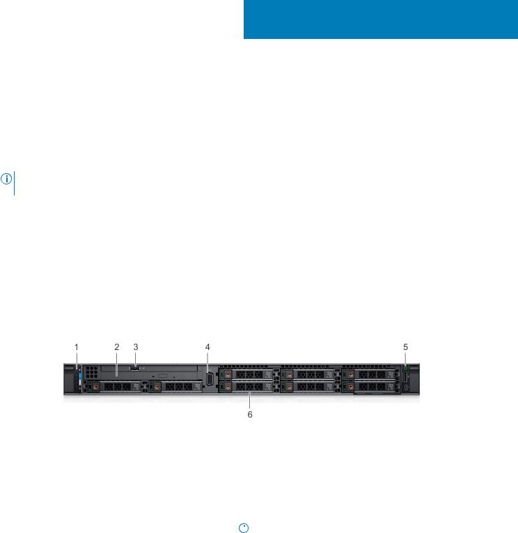
Front view of the system
The front view displays the features available on the front of the system.
Figure 1. Front view of 8 x 2.5-inch drive system
Table 1. Features available on the front of the system
Item |
Ports, panels, and |
Icon |
Description |
||
|
slots |
|
|
|
|
|
|
|
|
||
1 |
Left control panel |
N/A |
Contains the system health and system ID, status LED, and the |
||
|
|
|
iDRAC Quick Sync 2 (wireless) indicator. |
||
|
|
|
|
|
NOTE: The iDRAC Quick Sync 2 indicator is available only |
|
|
|
|
|
|
|
|
|
|
||
|
|
|
|
|
on certain configurations. |
|
|
|
● Status LED: Enables you to identify any failed hardware |
||
|
|
|
|
|
components. There are up to five status LEDs and an overall |
|
|
|
|
|
system health LED (Chassis health and system ID) bar. For |
|
|
|
|
|
more information, see the Status LED indicators section. |
|
|
|
● Quick Sync 2 (wireless): Indicates a Quick Sync enabled |
||
|
|
|
|
|
system. The Quick Sync feature is optional. This feature |
|
|
|
|
|
allows management of the system by using mobile devices. |
|
|
|
|
|
This feature aggregates hardware or firmware inventory and |
|
|
|
|
|
various system level diagnostic and error information that |
|
|
|
|
|
can be used in troubleshooting the system. For more |
|
|
|
|
|
|
Dell EMC PowerEdge R440 system overview |
7 |
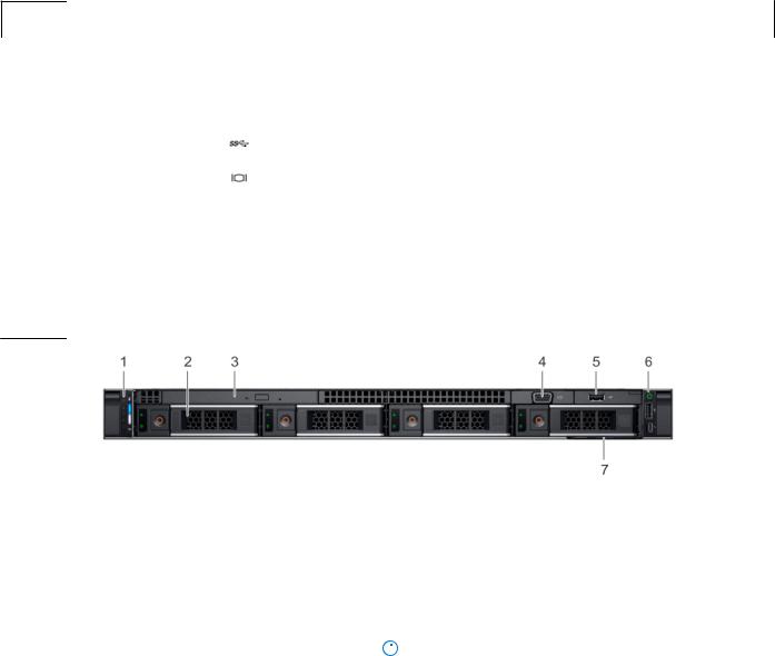
Table 1. Features available on the front of the system (continued)
Item |
Ports, panels, and |
Icon |
Description |
|
|
slots |
|
|
|
|
|
|
|
|
|
|
|
information, see the Integrated Dell Remote Access |
|
|
|
|
Controller User’s Guide at www.dell.com/ |
|
|
|
|
poweredgemanuals. |
|
2 |
Optical drive (optional) |
N/A |
One optional slim SATA DVD-ROM drive or DVD+/-RW drive. |
|
3 |
USB port (optional) |
|
The USB port is USB 2.0 compliant. |
|
4 |
VGA port |
|
Enables you to connect a display device to the system. |
|
|
|
|
For more information, see the PowerEdge R440 Technical |
|
|
|
|
Specs at www.dell.com/poweredgemanuals |
|
5 |
Right control panel |
N/A |
Contains the power button, USB port, iDRAC Direct micro port, |
|
|
|
|
and the iDRAC Direct status LED. |
|
6 |
Drive slots |
N/A |
|
|
|
|
|||
Enable you to install drives that are supported on your system.
For more information, see the PowerEdge R440 Technical
Specs at www.dell.com/poweredgemanuals
Figure 2. Front view of 4 x 3.5-inch drive system
Table 2. Features available on the front of the system
Item |
Ports, panels, and |
Icon |
Description |
||
|
slots |
|
|
|
|
|
|
|
|
||
1 |
Left control panel |
N/A |
Contains the system health and system ID, status LED, and the |
||
|
|
|
iDRAC Quick Sync 2 (wireless) indicator. |
||
|
|
|
|
|
NOTE: The iDRAC Quick Sync 2 indicator is available only |
|
|
|
|
|
|
|
|
|
|
||
|
|
|
|
|
on certain configurations. |
|
|
|
● Status LED: Enables you to identify any failed hardware |
||
|
|
|
|
|
components. There are up to five status LEDs and an overall |
|
|
|
|
|
system health LED (Chassis health and system ID) bar. For |
|
|
|
|
|
more information, see the Status LED indicators section. |
|
|
|
● Quick Sync 2 (wireless): Indicates a Quick Sync enabled |
||
|
|
|
|
|
system. The Quick Sync feature is optional. This feature |
|
|
|
|
|
allows management of the system by using mobile devices. |
|
|
|
|
|
This feature aggregates hardware or firmware inventory and |
|
|
|
|
|
various system level diagnostic and error information that |
|
|
|
|
|
can be used in troubleshooting the system. For more |
|
|
|
|
|
information, see the Integrated Dell Remote Access |
|
|
|
|
|
Controller User’s Guide at www.dell.com/ |
|
|
|
|
|
poweredgemanuals. |
2 |
Drive slots |
N/A |
Enable you to install drives that are supported on your system. |
||
|
|
|
For more information, see the PowerEdge R440 Technical |
||
|
|
|
Specs at www.dell.com/poweredgemanuals |
||
3 |
Optical drive (optional) |
N/A |
One optional slim SATA DVD-ROM drive or DVD+/-RW drive. |
||
|
|
|
|
|
|
8 Dell EMC PowerEdge R440 system overview
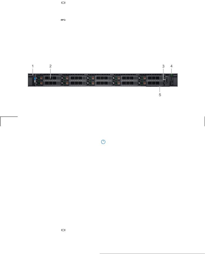
Table 2. Features available on the front of the system (continued)
Item |
Ports, panels, and |
Icon |
Description |
|
slots |
|
|
|
|
|
|
4 |
VGA port |
|
Enables you to connect a display device to the system. For more |
|
|
|
information, see the PowerEdge R440 Technical Specs at |
|
|
|
www.dell.com/poweredgemanuals |
5 |
USB port (optional) |
|
The USB port is USB 2.0 compliant. |
6 |
Right control panel |
N/A |
Contains the power button, USB port, iDRAC Direct micro port, |
|
|
|
and the iDRAC Direct status LED. |
7 |
Information Tag |
N/A |
|
The Information Tag is a slide-out label panel that contains |
|||
|
|
|
system information such as Service Tag, NIC, MAC address, and |
|
|
|
so on. If you have opted for the secure default access to iDRAC, |
|
|
|
the Information tag also contains the iDRAC secure default |
|
|
|
password. |
|
|
|
|
Figure 3. Front view of 10 x 2.5-inch drive system
Table 3. Features available on the front of the system
Item |
Ports, panels, and |
Icon |
Description |
||
|
slots |
|
|
|
|
|
|
|
|
||
1 |
Left control panel |
N/A |
Contains the system health and system ID, status LED, and the |
||
|
|
|
iDRAC Quick Sync 2 (wireless) indicator. |
||
|
|
|
|
|
NOTE: The iDRAC Quick Sync 2 indicator is available only |
|
|
|
|
|
|
|
|
|
|
||
|
|
|
|
|
on certain configurations. |
|
|
|
|
|
|
2 |
Drive slots |
N/A |
3 |
VGA port |
|
4 |
Right control panel |
N/A |
●Status LED: Enables you to identify any failed hardware components. There are up to five status LEDs and an overall system health LED (Chassis health and system ID) bar. For more information, see the Status LED indicators section.
●Quick Sync 2 (wireless): Indicates a Quick Sync enabled system. The Quick Sync feature is optional. This feature allows management of the system by using mobile devices. This feature aggregates hardware or firmware inventory and various system level diagnostic and error information that can be used in troubleshooting the system. For more information, see the Integrated Dell Remote Access Controller User’s Guide at www.dell.com/ poweredgemanuals.
Enable you to install drives that are supported on your system. For more information, see the PowerEdge R440 Technical Specs at www.dell.com/poweredgemanuals
Enables you to connect a display device to the system. For more information, see the PowerEdge R440 Technical Specs at www.dell.com/poweredgemanuals
Contains the power button, USB port, iDRAC Direct micro port, and the iDRAC Direct status LED.
Dell EMC PowerEdge R440 system overview |
9 |
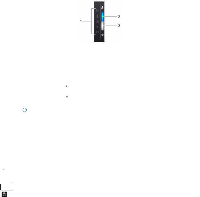
Table 3. Features available on the front of the system (continued)
Item |
Ports, panels, and |
Icon |
Description |
|
slots |
|
|
|
|
|
|
5 |
Information Tag |
N/A |
The Information Tag is a slide-out label panel that contains |
|
|
|
system information such as Service Tag, NIC, MAC address, and |
|
|
|
so on. If you have opted for the secure default access to iDRAC, |
|
|
|
the Information tag also contains the iDRAC secure default |
|
|
|
password. |
|
|
|
|
Left control panel view
Figure 4. Left control panel with optional iDRAC Quick Sync 2.0 indicator
Table 4. Left control panel
Item |
Indicator, button, or |
Icon |
Description |
||
|
connector |
|
|
||
|
|
|
|
||
|
|
|
|
|
|
1 |
Status LED indicators |
N/A |
Indicate the status of the system. For more information, see the |
||
|
|
|
|
|
Status LED indicators section. |
|
System health and system |
|
Indicates the system health. |
||
2 |
|
||||
|
ID indicator |
|
|
||
|
iDRAC Quick Sync 2 |
|
Indicates if the iDRAC Quick Sync 2 wireless option is activated. |
||
3 |
|
||||
|
wireless indicator |
|
The Quick Sync 2 feature allows management of the system |
||
|
(optional) |
|
using mobile devices. This feature aggregates hardware/ |
||
|
|
|
NOTE: iDRAC Quick |
|
firmware inventory and various system level diagnostic/error |
|
|
|
|
||
|
|
|
|||
|
|
|
Sync 2 wireless |
|
information that can be used in troubleshooting the system. |
|
|
|
indicator is available |
|
You can access system inventory, Dell Lifecycle Controller logs |
|
|
|
|
or system logs, system health status, and also configure iDRAC, |
|
|
|
|
only on certain |
|
|
|
|
|
|
BIOS, and networking parameters. You can also launch the |
|
|
|
|
configurations. |
|
|
|
|
|
|
virtual Keyboard, Video, and Mouse (KVM) viewer and virtual |
|
|
|
|
|
|
|
|
|
|
|
|
Kernel based Virtual Machine (KVM), on a supported mobile |
|
|
|
|
|
device. For more information, see the Integrated Dell Remote |
|
|
|
|
|
Access Controller User's Guide at www.dell.com/ |
|
|
|
|
|
poweredgemanuals |
|
|
|
|
|
|
Status LED indicators

 NOTE: The indicators display solid amber if any error occurs.
Table 5. Status LED indicators and descriptions
Icon |
Description Condition |
Corrective action |
Drive |
The indicator turns solid amber, |
indicator |
if there is a drive error. |
●Check the System event log to determine if the drive has an error.
●Run the appropriate Online Diagnostics test. Restart the system, and run embedded diagnostics (ePSA).
10 Dell EMC PowerEdge R440 system overview
11

iDRAC Quick Sync 2 indicator codes
iDRAC Quick Sync 2 module (optional) is located on the left control panel of your system.
Figure 6. iDRAC Quick Sync 2 indicators
Table 7. iDRAC Quick Sync 2 indicators and descriptions
iDRAC Quick Sync 2 indicator Condition code
Off (default state) |
Indicates that the iDRAC Quick Sync 2 |
|
feature is turned off. Press the iDRAC |
|
Quick Sync 2 button to turn on the |
|
iDRAC Quick Sync 2 feature. |
Solid white |
Indicates that iDRAC Quick Sync 2 is |
|
ready to communicate. Press the iDRAC |
|
Quick Sync 2 button to turn off. |
Blinks white rapidly |
Indicates data transfer activity. |
Corrective action
If the LED fails to turn on, reseat the left control panel flex cable and check. If the problem persists, see the Getting help section.
If the LED fails to turn off, restart the system. If the problem persists, see the Getting help section.
If the indicator continues to blink indefinitely, see the Getting help section.
Blinks white slowly |
Indicates that firmware update is in |
|
progress. |
Blinks white five times rapidly |
Indicates that the iDRAC Quick Sync 2 |
and then turns off |
feature is disabled. |
Solid amber |
Indicates that the system is in fail-safe |
|
mode. |
Blinking amber |
Indicates that the iDRAC Quick Sync 2 |
|
hardware is not responding properly. |
If the indicator continues to blink indefinitely, see the Getting help section.
Check if iDRAC Quick Sync 2 feature is configured to be disabled by iDRAC. If the problem persists, see the Getting help section. For more information, see Integrated Dell Remote Access Controller User's Guide at www.dell.com/ poweredgemanuals or Dell OpenManage Server Administrator User’s Guide at www.dell.com/ openmanagemanuals > OpenManage Server Administrator
Restart the system. If the problem persists, see the Getting help section.
Restart the system. If the problem persists, see the Getting help section.
12 Dell EMC PowerEdge R440 system overview
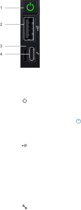
Right control panel view
Figure 7. Right control panel
Table 8. Right control panel
Item |
Indicator or button |
Icon |
Description |
||
|
|
|
|
||
|
|
|
|
|
|
1 |
Power button |
|
Indicates if the system is |
||
|
|
|
powered on or off. Press the |
||
|
|
|
power button to manually |
||
|
|
|
power on or off the system. |
||
|
|
|
|
|
NOTE: Press the power |
|
|
|
|
|
|
|
|
|
|
||
|
|
|
|
|
button to gracefully shut |
|
|
|
|
|
down an ACPI-compliant |
|
|
|
|
|
operating system. |
|
USB port |
|
|
||
2 |
|
The USB ports are 4-pin, 2.0- |
|||
|
|
|
compliant. This port enables |
||
|
|
|
you to connect USB devices |
||
|
|
|
to the system. |
||
|
iDRAC Direct LED |
N/A |
The iDRAC Direct LED |
||
3 |
|||||
|
|
|
indicator lights up to indicate |
||
|
|
|
that the iDRAC Direct port is |
||
|
|
|
actively connected to a |
||
|
|
|
device. For more information, |
||
|
|
|
see the iDRAC Direct LED |
||
|
|
|
indicator codes on page 14 |
||
|
|
|
section. |
||
|
iDRAC Direct port (Micro-AB |
|
The iDRAC Direct (Micro-AB |
||
4 |
|
||||
|
USB) |
|
USB) port enables you to |
||
|
|
|
access the iDRAC Direct |
||
|
|
|
(Micro-AB) features. For |
||
|
|
|
more information, see the |
||
|
|
|
Integrated Dell Remote |
||
|
|
|
Access Controller User's |
||
|
|
|
Guide at www.dell.com/ |
||
|
|
|
poweredgemanuals |
||
|
|
|
|
|
|
Dell EMC PowerEdge R440 system overview |
13 |
iDRAC Direct LED indicator codes
The iDRAC Direct LED indicator lights up to indicate that the port is connected and is being used as a part of the iDRAC subsystem.
You can configure iDRAC Direct by using a USB to micro USB (type AB) cable, which you can connect to your laptop or tablet. The following table describes iDRAC Direct activity when the iDRAC Direct port is active:
Table 9. iDRAC Direct LED indicator codes
iDRAC Direct LED indicator code
Solid green for two seconds
Flashing green (on for two seconds and off for two seconds)
Turns off
Condition
Indicates that the laptop or tablet is connected.
Indicates that the laptop or tablet connected is recognized.
Indicates that the laptop or tablet is unplugged.
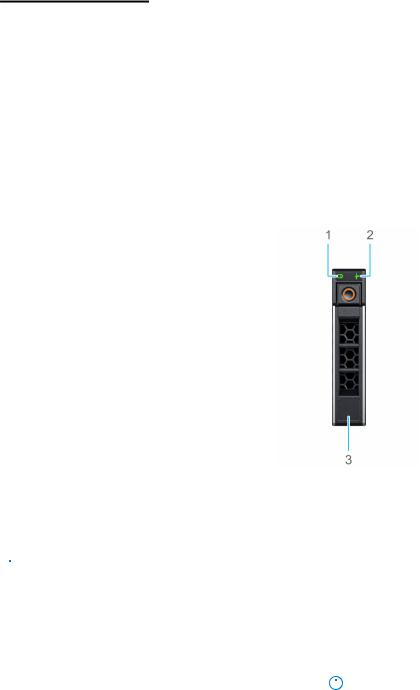
Drive indicator codes
Each drive carrier has an activity LED indicator and a status LED indicator. The indicators provide information about the current status of the drive. The activity LED indicator indicates whether the drive is currently in use or not. The status LED indicator indicates the power condition of the drive.
Figure 8. Drive indicators
1.Drive activity LED indicator
2.Drive status LED indicator
3.Drive capacity label

 NOTE: If the drive is in the Advanced Host Controller Interface (AHCI) mode, the status LED indicator does not turn on.
Table 10. Drive indicator codes
Drive status indicator code |
Condition |
||
|
|
||
Flashes green twice per second |
Identifying drive or preparing for removal. |
||
Off |
Drive ready for removal. |
||
|
|
|
NOTE: The drive status indicator remains off until all drives |
|
|
||
|
|
|
are initialized after the system is turned on. Drives are not |
|
|
|
ready for removal during this time. |
Flashes green, amber, and then turns off |
Predicted drive failure. |
||
|
|
|
|
14 Dell EMC PowerEdge R440 system overview

Table 10. Drive indicator codes (continued)
Drive status indicator code |
Condition |
|
|
Flashes amber four times per second |
Drive failed. |
Flashes green slowly |
Drive rebuilding. |
Solid green |
Drive online. |
Flashes green for three seconds, amber for three |
Rebuild stopped. |
seconds, and then turns off after six seconds |
|
|
|
Back view of the system
The back view displays the features available on the back of the system.
Figure 9. Back view of the system with full height riser
Table 11. Back view of the system with full height riser
Item |
Ports, panels, or slots |
Icon |
Description |
|
|
|
|
1 |
Serial port |
|
Use the serial port to connect a serial device to the system. For |
|
|
|
more information, see the PowerEdge R440 Technical Specs at |
|
|
|
www.dell.com/poweredgemanuals . |
2 |
iDRAC9 dedicated |
NA |
Use the iDRAC9 dedicated network port to securely access the |
|
network port |
|
embedded iDRAC on a separate management network, see the |
|
|
|
Integrated Dell Remote Access Controller User's Guide at |
|
|
|
www.dell.com/poweredgemanuals |
3 |
Ethernet ports (2) |
|
Use the Ethernet ports to connect Local Area Networks (LANs) to |
|
|
|
the system. For more information about the supported Ethernet |
|
|
|
ports, see the PowerEdge R440 Technical Specs at www.dell.com/ |
|
|
|
poweredgemanuals |
4 |
Full height riser slot |
N/A |
Use the card slots to connect full-height PCIe expansion cards on |
|
|
|
full height riser. |
5 |
Power supply unit (PSU) |
N/A |
For more information about the PSU configurations, see the |
|
|
|
PowerEdge R440 Technical Specs at www.dell.com/ |
|
|
|
poweredgemanuals |
6 |
Power supply unit (PSU) |
N/A |
For more information about the PSU configurations, see the |
|
|
|
PowerEdge R440 Technical Specs at www.dell.com/ |
|
|
|
poweredgemanuals |
7 |
LOM riser ports (2) |
|
For more information about the PSU configurations, see the |
|
|
|
PowerEdge R440 Technical Specs at www.dell.com/ |
|
|
|
poweredgemanuals |
8 |
USB 3.0 port (2) |
|
Use the USB 3.0 port to connect USB devices to the system. |
|
|
|
These ports are 4-pin, USB 3.0-compliant. |
9 |
VGA port |
|
Use the VGA port to connect a display to the system. For more |
|
|
|
information about the supported VGA port, see the PowerEdge |
|
|
|
R440 Technical Specs at www.dell.com/poweredgemanuals . |
|
|
|
|
Dell EMC PowerEdge R440 system overview |
15 |

Table 11. Back view of the system with full height riser (continued)
Item |
Ports, panels, or slots |
Icon |
Description |
||
|
|
|
|
||
10 |
System status indicator |
N/A |
Enables you to connect the status indicator cable and view system |
||
|
cable port |
|
status when the CMA is installed. |
||
11 |
System identification |
|
Press the system ID button: |
||
|
button |
|
● To locate a particular system within a rack. |
||
|
|
|
|||
|
|
|
● To turn the system ID on or off. |
||
|
|
|
To reset iDRAC, press and hold the button for more than 15 |
||
|
|
|
seconds. |
||
|
|
|
|
|
NOTE: |
|
|
|
|
||
|
|
|
|
|
● To reset iDRAC using system ID, ensure that the system ID |
|
|
|
|
|
button is enabled in the iDRAC setup. |
|
|
|
|
|
● If the system stops responding during POST, press and hold |
|
|
|
|
|
the system ID button (for more than five seconds) to enter |
|
|
|
|
|
the BIOS progress mode. |
|
|
|
|
|
|
Figure 10. Back view of the system with 2 risers
Table 12. Back view of the system with 2 risers
Item |
Ports, panels, or slots |
Icon |
Description |
|
|
|
|
1 |
Serial port |
|
Use the serial port to connect a serial device to the system. For |
|
|
|
more information, see the PowerEdge R440 Technical Specs at |
|
|
|
www.dell.com/poweredgemanuals . |
2 |
iDRAC9 dedicated |
NA |
Use the iDRAC9 dedicated network port to securely access the |
|
network port |
|
embedded iDRAC on a separate management network, see the |
Integrated Dell Remote Access Controller User's Guide at
www.dell.com/poweredgemanuals
3 |
Ethernet ports (2) |
|
4 |
Low profile riser right slot |
N/A |
5 |
Low profile riser left slot |
N/A |
6 |
Cabled PSU |
N/A |
7 |
LOM riser ports (2) |
|
8 |
USB 3.0 port (2) |
|
9 |
VGA port |
|
Use the Ethernet ports to connect Local Area Networks (LANs) to the system. For more information, see the PowerEdge R440 Technical Specs at www.dell.com/poweredgemanuals
Use the card slot to connect half-height PCIe expansion card on low profile riser.
Use the card slot to connect half-height PCIe expansion card on low profile riser.
FFor more information, see the PowerEdge R440 Technical Specs at www.dell.com/poweredgemanuals
For more information, see the PowerEdge R440 Technical Specs at www.dell.com/poweredgemanuals
Use the USB 3.0 port to connect USB devices to the system. These ports are 4-pin, USB 3.0-compliant.
Use the VGA port to connect a display to the system. For more information, see the PowerEdge R440 Technical Specs at www.dell.com/poweredgemanuals
16 Dell EMC PowerEdge R440 system overview

Table 12. Back view of the system with 2 risers (continued)
Item |
Ports, panels, or slots |
Icon |
Description |
||
|
|
|
|
||
10 |
System status indicator |
N/A |
Enables you to connect the status indicator cable and view system |
||
|
cable port |
|
status when the CMA is installed. |
||
11 |
System identification |
|
Press the system ID button: |
||
|
button |
|
● To locate a particular system within a rack. |
||
|
|
|
|||
|
|
|
● To turn the system ID on or off. |
||
|
|
|
To reset iDRAC, press and hold the button for more than 15 |
||
|
|
|
seconds. |
||
|
|
|
|
|
NOTE: |
|
|
|
|
||
|
|
|
|
|
● To reset iDRAC using system ID, ensure that the system ID |
|
|
|
|
|
button is enabled in the iDRAC setup. |
|
|
|
|
|
● If the system stops responding during POST, press and hold |
|
|
|
|
|
the system ID button (for more than five seconds) to enter |
|
|
|
|
|
the BIOS progress mode. |
|
|
|
|
|
|
NIC indicator codes
Each NIC on the back of the system has indicators that provide information about the activity and link status. The activity LED indicator indicates if data is flowing through the NIC, and the link LED indicator indicates the speed of the connected network.
Figure 11. NIC indicator codes
1. link LED indicator
2. activity LED indicator
Table 13. NIC indicator codes
Status |
Condition |
|
|
Link and activity indicators are off |
The NIC is not connected to the network. |
Link indicator is green and activity indicator is blinking |
The NIC is connected to a valid network at its maximum port speed |
green |
and data is being sent or received. |
Link indicator is amber and activity indicator is blinking |
The NIC is connected to a valid network at less than its maximum |
green |
port speed and data is being sent or received. |
Link indicator is green and activity indicator is off |
The NIC is connected to a valid network at its maximum port speed |
|
and data is not being sent or received. |
Link indicator is amber and activity indicator is off |
The NIC is connected to a valid network at less than its maximum |
|
port speed and data is not being sent or received. |
Link indicator is blinking green and activity is off |
NIC identify is enabled through the NIC configuration utility. |
|
|
Power supply unit indicator codes
AC power supply units (PSUs) have an illuminated translucent handle that serves as an indicator. The indicator shows whether power is present or if a power fault has occurred.
Dell EMC PowerEdge R440 system overview |
17 |
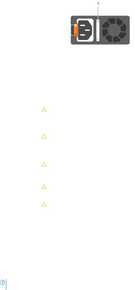
Figure 12. AC PSU status indicator
1. AC PSU status indicator/handle
Table 14. AC PSU status indicator codes
Power indicator codes |
Condition |
|
|
|
|
Green |
A valid power source is connected to the PSU and the PSU is operational. |
|
Blinking amber |
Indicates a problem with the PSU. |
|
Not illuminated |
Power is not connected to the PSU. |
|
Blinking green |
When the firmware of the PSU is being updated, the PSU handle blinks green. |
|
|
|
CAUTION: Do not disconnect the power cord or unplug the PSU when updating |
|
|
firmware. If firmware update is interrupted, the PSUs do not function. |
Blinking green and turns |
When hot-plugging a PSU, the PSU handle blinks green five times at a rate of 4 Hz and turns off. |
|
off |
This indicates a PSU mismatch with respect to efficiency, feature set, health status, or supported |
|
|
voltage. |
|
|
|
CAUTION: If two PSUs are installed, both the PSUs must have the same type of label; |
|
|
for example, Extended Power Performance (EPP) label. Mixing PSUs from previous |
|
|
generations of PowerEdge servers is not supported, even if the PSUs have the same |
|
|
power rating. This results in a PSU mismatch condition or failure to turn the system |
|
|
on. |
|
|
CAUTION: When correcting a PSU mismatch, replace only the PSU with the blinking |
|
|
|
|
|
indicator. Swapping the PSU to make a matched pair can result in an error condition |
|
|
and unexpected system shutdown. To change from a high output configuration to a |
|
|
low output configuration or vice versa, you must turn off the system. |
|
|
CAUTION: AC PSUs support both 240 V and 120 V input voltages with the exception of |
|
|
|
|
|
Titanium PSUs, which support only 240 V. When two identical PSUs receive different |
|
|
input voltages, they can output different wattages, and trigger a mismatch. |
|
|
CAUTION: If two PSUs are used, they must be of the same type and have the same |
|
|
|
|
|
maximum output power. |
|
|
|
LCD panel
The LCD panel provides system information, status, and error messages to indicate if the system is functioning correctly or requires attention. The LCD panel can also be used to configure or view the system’s iDRAC IP address. For information about the event and error messages generated by the system firmware and agents that monitor system components, go to qrl.dell.com > Look Up > Error Code, type the error code, and then click Look it up..
The LCD panel is available only on the optional front bezel. The optional front bezel is hot pluggable.
The statuses and conditions of the LCD panel are outlined here:
●The LCD backlight is white during normal operating conditions.
●When the system needs attention, the LCD backlight turns amber, and displays an error code followed by descriptive text. NOTE: If the system is connected to a power source and an error is detected, the LCD turns amber regardless of
whether the system is turned on or off.
18 Dell EMC PowerEdge R440 system overview

●When the system turns off and there are no errors, LCD enters the standby mode after five minutes of inactivity. Press any button on the LCD to turn it on.
●If the LCD panel stops responding, remove the bezel and reinstall it. If the problem persists, see Getting help.
●The LCD backlight remains off if LCD messaging is turned off using the iDRAC utility, the LCD panel, or other tools.
Figure 13. LCD panel features
Table 15. LCD panel features
Item |
Button or |
Description |
||
|
display |
|
|
|
|
|
|
||
|
|
|
|
|
1 |
Left |
Moves the cursor back in one-step increments. |
||
|
|
|
||
2 |
Select |
Selects the menu item highlighted by the cursor. |
||
|
|
|
||
3 |
Right |
Moves the cursor forward in one-step increments. |
||
|
|
During message scrolling: |
||
|
|
● Press and hold the right button to increase scrolling speed. |
||
|
|
● Release the button to stop. |
||
|
|
|
|
NOTE: The display stops scrolling when the button is released. After 45 seconds of inactivity, |
|
|
|
|
|
|
|
|
||
|
|
|
|
the display starts scrolling. |
|
|
|
||
4 |
LCD display |
Displays system information, status, and error messages or iDRAC IP address. |
||
|
|
|
|
|
Viewing Home screen
The Home screen displays user-configurable information about the system. This screen is displayed during normal system operation when there are no status messages or errors. When the system turns off and there are no errors, LCD enters the standby mode after five minutes of inactivity. Press any button on the LCD to turn it on.
Steps
1.To view the Home screen, press one of the three navigation buttons (Select, Left, or Right).
2.To navigate to the Home screen from another menu, complete the following steps:
a.Press and hold the navigation button until the up arrow  is displayed.
b.Navigate to the Home icon  using the up arrow
  .
.
c.Select the Home icon.
d.On the Home screen, press the Select button to enter the main menu.
Setup menu

 NOTE: When you select an option in the Setup menu, you must confirm the option before proceeding to the next action.
Option |
Description |
iDRAC |
Select DHCP or Static IP to configure the network mode. If Static IP is selected, the available fields are |
|
IP, Subnet (Sub), and Gateway (Gtw). Select Setup DNS to enable DNS and to view domain |
|
addresses. Two separate DNS entries are available. |
Dell EMC PowerEdge R440 system overview |
19 |
Option |
Description |
Set error |
Select SEL to view LCD error messages in a format that matches the IPMI description in the SEL. This |
|
enables you to match an LCD message with an SEL entry. |
|
Select Simple to view LCD error messages in a simplified user-friendly description. For information about |
|
the event and error messages generated by the system firmware and agents that monitor system |
|
components, go to qrl.dell.com > Look Up > Error Code, type the error code, and then click Look it up. |
Set home |
Select the default information to be displayed on the Home screen. See View menu section for the |
|
options and option items that can be set as the default on the Home screen. |
View menu

 NOTE: When you select an option in the View menu, you must confirm the option before proceeding to the next action.
Option |
Description |
iDRAC IP |
Displays the IPv4 or IPv6 addresses for iDRAC9. Addresses include DNS (Primary and Secondary), |
|
Gateway, IP, and Subnet (IPv6 does not have Subnet). |
MAC |
Displays the MAC addresses for iDRAC, iSCSI, or Network devices. |
Name |
Displays the name of the Host, Model, or User String for the system. |
Number |
Displays the Asset tag or the Service tag for the system. |
Power |
Displays the power output of the system in BTU/hr or Watts. The display format can be configured in the |
|
Set home submenu of the Setup menu. |
Temperature |
Displays the temperature of the system in Celsius or Fahrenheit. The display format can be configured in |
|
the Set home submenu of the Setup menu. |
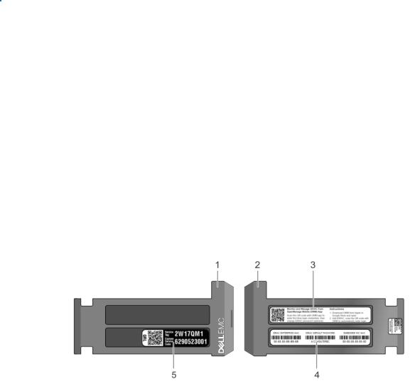
Locating the Service Tag of your system
You can identify your system using the unique Express Service Code and Service Tag. Pull out the information tag in front of the system to view the Express Service Code and Service Tag. Alternatively, the information may be on a sticker on the chassis of the system. The mini Enterprise Service Tag (EST) is found on the back of the system. This information is used by Dell to route support calls to the appropriate personnel.
Figure 14. Locating Service Tag of your system |
|
|
|
1. |
Information tag (front view) |
2. |
Information tag (back view) |
3. |
OpenManage Mobile (OMM) label |
4. |
iDRAC MAC address and iDRAC secure password label |
5. |
Service Tag |
|
|
20 Dell EMC PowerEdge R440 system overview

System Label Information
Service and Memory Information Label
Figure 15. Service and memory information label
Dell EMC PowerEdge R440 system overview |
21 |

2
Initial system setup and configuration
Topics:
•Setting up your system
•iDRAC configuration
•Options to install the operating system
Setting up your system
Perform the following steps to set up your system:
Steps
1.Unpack the system.
2.Install the system into the rack. For more information about installing the system into the rack, see the Rail Installation Guide at www.dell.com/poweredgemanuals.
3.Connect the peripherals to the system.
4.Connect the system to its electrical outlet.
5.Power on the system by pressing the power button or by using iDRAC.
6.Power on the attached peripherals.
For more information about setting up your system, see the Getting Started Guide that shipped with your system.
iDRAC configuration
The Integrated Dell Remote Access Controller (iDRAC) is designed to make system administrators more productive and improve the overall availability of Dell systems. iDRAC alerts administrators about system issues and enables them to perform remote system management. This reduces the need for physical access to the system.
Options to set up iDRAC IP address
To enable communication between your system and iDRAC, you must first configure the network settings based on your network infrastructure.

 NOTE: For static IP configuration, you must request for it at the time of purchase.
This option is set to DHCP by Default. You can set up the IP address by using one of the following interfaces:
Interfaces |
Document/Section |
iDRAC Settings |
Dell Integrated Dell Remote Access Controller User's Guide at www.dell.com/poweredgemanuals |
utility |
|
Dell Deployment |
Dell Deployment Toolkit User’s Guide at www.dell.com/openmanagemanuals > OpenManage Deployment |
Toolkit |
Toolkit |
Dell Lifecycle |
Dell Lifecycle Controller User’s Guide at www.dell.com/poweredgemanuals |
Controller |
|
Server LCD panel LCD panel section
NOTE: To access iDRAC, ensure that you connect the ethernet cable to the iDRAC9 dedicated network port. You can also access iDRAC through the shared LOM mode, if you have opted for a system that has the shared LOM mode enabled.
22 Initial system setup and configuration

Log in to iDRAC
You can log in to iDRAC as:
●iDRAC user
●Microsoft Active Directory user
●Lightweight Directory Access Protocol (LDAP) user
If you have opted for secure default access to iDRAC, you must use the iDRAC secure default password available on the system Information tag. If you have not opted for secure default access to iDRAC, then use the default user name and password –root and calvin. You can also log in by using your Single Sign-On or Smart Card.

 NOTE: You must have the iDRAC credentials to log in to iDRAC.

 NOTE: Ensure that you change the default username and password after setting up the iDRAC IP address.
For more information about logging in to the iDRAC and iDRAC licenses, see the latest Integrated Dell Remote Access Controller User's Guide at www.dell.com/poweredgemanuals.
You can also access iDRAC by using RACADM. For more information, see the RACADM Command Line Interface Reference Guide at www.dell.com/poweredgemanuals.
Options to install the operating system
If the system is shipped without an operating system, install a supported operating system by using one of the following resources:
Table 16. Resources to install the operating system
Resources |
Location |
|
|
|
|
iDRAC |
www.dell.com/idracmanuals |
|
|
Lifecycle Controller |
www.dell.com/idracmanuals > Lifecycle Controller |
|
|
OpenManage Deployment Toolkit |
www.dell.com/openmanagemanuals > OpenManage |
|
Deployment Toolkit |
|
|
Dell certified VMware ESXi |
www.dell.com/virtualizationsolutions |
|
|
Installation and How-to videos for supported operating |
Supported Operating Systems for Dell EMC PowerEdge |
systems on PowerEdge systems |
systems |
|
|
Methods to download firmware and drivers
You can download the firmware and drivers by using any of the following methods:
Table 17. Firmware and drivers
Methods |
Location |
|
|
|
|
From the Dell EMC support site |
www.dell.com/support/home |
|
|
Using Dell Remote Access Controller Lifecycle Controller |
www.dell.com/idracmanuals |
(iDRAC with LC) |
|
|
|
Using Dell Repository Manager (DRM) |
www.dell.com/openmanagemanuals > Repository Manager |
|
|
Using Dell OpenManage Essentials |
www.dell.com/openmanagemanuals > OpenManage Essentials |
|
|
Using Dell OpenManage Enterprise |
www.dell.com/openmanagemanuals > OpenManage |
|
Enterprise |
|
|
Using Dell Server Update Utility (SUU) |
www.dell.com/openmanagemanuals > Server Update Utility |
|
|
Initial system setup and configuration |
23 |

Table 17. Firmware and drivers (continued)
Methods |
Location |
|
|
|
|
Using Dell OpenManage Deployment Toolkit (DTK) |
www.dell.com/openmanagemanuals > OpenManage |
|
Deployment Toolkit |
|
|
Using iDRAC virtual media |
www.dell.com/idracmanuals |
|
|
Downloading drivers and firmware
Dell EMC recommends that you download and install the latest BIOS, drivers, and systems management firmware on your system.
Prerequisites
Ensure that you clear the web browser cache before downloading the drivers and firmware.
Steps
1.Go to www.dell.com/support/home.
2.In the Drivers & Downloads section, type the Service Tag of your system in the Enter a Service Tag or product ID box, and then click Submit.
 NOTE: If you do not have the Service Tag, select Detect Product to allow the system to automatically detect the Service Tag, or click View products, and navigate to your product.
3.Click Drivers & Downloads.
The drivers that are applicable to your system are displayed.
4.Download the drivers to a USB drive, CD, or DVD.
24 Initial system setup and configuration

3
Installing and removing system components
Topics:
•Safety instructions
•Before working inside your system
•After working inside your system
•Recommended tools
•Optional front bezel
•System cover
•Inside the system
•Backplane cover
•Air shroud
•Cooling fans
•Intrusion switch
•Drives
•System memory
•Processors and heat sinks
•Internal PERC riser
•Expansion cards and expansion card risers
•M.2 SSD module
•Optional MicroSD or vFlash card
•Optional IDSDM or vFlash module
•LOM riser card
•Hard drive backplane
•Cable routing
•System battery
•Optional internal USB memory key
•Optical drive (optional)
•Power supply units
•Power interposer board
•Control panel
•System board
•Trusted Platform Module
Safety instructions
NOTE: Whenever you need to lift the system, get others to assist you. To avoid injury, do not attempt to lift the system by yourself.
 WARNING: Opening or removing the system cover while the system is powered on may expose you to a risk of electric shock.
 CAUTION: Do not operate the system without the cover for a duration exceeding five minutes. Operating the system without the system cover can result in component damage.
 CAUTION: Many repairs may only be done by a certified service technician. You should only perform troubleshooting and simple repairs as authorized in your product documentation, or as directed by the online or telephone service and support team. Damage due to servicing that is not authorized by Dell is not covered by your warranty. Read and follow the safety instructions that are shipped with your product.
Installing and removing system components |
25 |

NOTE: It is recommended that you always use an antistatic mat and antistatic strap while working on components inside the system.
CAUTION: To ensure proper operation and cooling, all bays in the system and system fans must be always populated with a component or a blank.
Before working inside your system
Prerequisites
Follow the safety guidelines listed in Safety instructions on page 25.
Steps
1.Turn off the system, including all attached peripherals.
2.Disconnect the system from the electrical outlet and disconnect the peripherals.
3.Remove the system cover.
After working inside your system
Prerequisites
Follow the safety guidelines listed in Safety instructions on page 25.
Steps
1.Install the system cover.
2.Reconnect the peripherals and connect the system to the electrical outlet.
3.Turn on the attached peripherals and then turn on the system.
Recommended tools
You need the following tools to perform the removal and installation procedures:
●Key to the bezel lock
The key is required only if your system includes a bezel.
●Phillips #1 screwdriver
●Phillips #2 screwdriver
●Torx #T30 screwdriver
●Torx #T8 screwdriver
●Wrist grounding strap
Optional front bezel
Removing the front bezel
The procedure to remove the front bezel with and without the LCD panel is the same.
Prerequisites
Follow the safety guidelines listed in Safety instructions on page 25.
26 Installing and removing system components
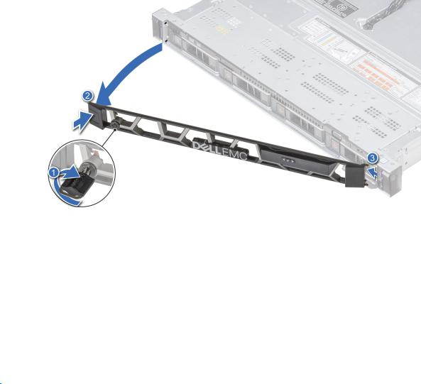
Steps
1.Unlock the bezel by using the bezel key.
2.Press the release button, and pull the left end of the bezel.
3.Unhook the right end, and remove the bezel.
Figure 16. Removing the front bezel with the LCD panel
Installing the front bezel
The procedure to install the front bezel with and without the LCD panel is the same.
Prerequisites
Follow the safety guidelines listed in Safety instructions on page 25.
Steps
1. Locate and remove the bezel key.

 NOTE: The bezel key is part of the LCD bezel package.
2.Align and insert the tabs on the bezel into the slots on the system.
3.Press the bezel until the button clicks in place.
4.Lock the bezel by using the key.
Installing and removing system components |
27 |
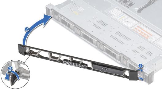
Figure 17. Installing the front bezel with the LCD panel
System cover
Removing the system cover
Prerequisites
1.Follow the safety guidelines listed in Safety instructions on page 25.
2.Turn off the system, including any attached peripherals.
3.Disconnect the system from the electrical outlet and disconnect the peripherals.
Steps
1.Using a 1/4 inch flat head or a Phillips #2 screwdriver, rotate the latch release lock counter clockwise to the unlocked position.
2.Lift the latch till the system cover slides back and the tabs on the system cover disengage from the guide slots on the system.
3.Hold the cover on both sides, and lift the cover away from the system.
28 Installing and removing system components

Figure 18. Removing the system cover
Installing the system cover
Prerequisites
1.Follow the safety guidelines listed in Safety instructions on page 25.
2.Ensure that all internal cables are routed correctly and connected, and no tools or extra parts are left inside the system.
Steps
1.Align the tabs on the system cover with the guide slots on the system.
2.Push the system cover latch down.
The system cover slides forward, the tabs on the system cover engage with the guide slots on the system and the system cover latch locks into place.
3.Using a 1/4 inch flat head or Phillips #2 screwdriver, rotate the latch release lock clockwise to the locked position.
Installing and removing system components |
29 |
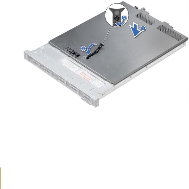
Figure 19. Installing the system cover
Next steps
1.Reconnect the peripherals and connect the system to the electrical outlet.
2.Turn on the system, including any attached peripherals.
Inside the system
 CAUTION: Many repairs may only be done by a certified service technician. You should only perform troubleshooting and simple repairs as authorized in your product documentation, or as directed by the online or telephone service and support team. Damage due to servicing that is not authorized by Dell is not covered by your warranty. Read and follow the safety instructions that are shipped with your product.
30 Installing and removing system components
Loading...