


IP Office 3.0

IP Office 3.0
Installation Manual
40DHB0002UKCL Issue 12c (24th February 2005)


Installation Manual Page iii
IP Office 3.0 40DHB0002UKCL Issue 12c (24th February 2005)
Table of Contents
Introduction ................................................................................................................................ 7
IP Office Installation.................................................................................................................................... 7
Scope of Manual......................................................................................................................................... 8
IP403 Office Platform.................................................................................................................9
IP403 Office................................................................................................................................................ 9
Expansion Modules .................................................................................................................................... 9
Integral Modules (Optional) ........................................................................................................................ 9
IP403 Office - Front View ......................................................................................................................... 10
IP403 Office - Rear View .......................................................................................................................... 11
IP403 Typical Configuration ..................................................................................................................... 12
Scenario............................................................................................................................................... 12
Kit List .................................................................................................................................................. 12
IP406 Office V2 Platform.......................................................................................................... 13
IP406 V2 Office ........................................................................................................................................ 13
Expansion Modules.............................................................................................................................. 13
Integral Modules (Optional).................................................................................................................. 13
IP406 V2 Office - Front View .................................................................................................................... 14
IP406 V2 Office - Rear View..................................................................................................................... 15
Typical Configurations .............................................................................................................................. 16
Scenario 1............................................................................................................................................ 16
Scenario 2............................................................................................................................................ 16
IP412 Office Platform............................................................................................................... 17
IP412 Office.............................................................................................................................................. 17
Expansion Modules.............................................................................................................................. 17
Integral Modules (Optional).................................................................................................................. 17
IP412 Office - Front View ......................................................................................................................... 18
IP412 Office - Rear View .......................................................................................................................... 19
Typical Configurations .............................................................................................................................. 20
IP412 Scenario 1 ................................................................................................................................. 20
IP412 Scenario 2 ................................................................................................................................. 21
Expansion Modules ................................................................................................................. 23
Introduction............................................................................................................................................... 23
IP400 Digital Stations 16/30 ..................................................................................................................... 24
IP400 Phone 8/16/30................................................................................................................................ 25
IP400 So8................................................................................................................................................. 26
IP400 WAN3............................................................................................................................................. 27
IP400 Analog Trunk 16............................................................................................................................. 28
Country Variants ...................................................................................................................... 29
Overview of Country Variants................................................................................................................... 29
IP400 Office Systems ............................................................................................................................... 30
IP403 Office ......................................................................................................................................... 30
IP406 V2 Office.................................................................................................................................... 30
IP412 Office ......................................................................................................................................... 30
IP Office Administration CD Set........................................................................................................... 30
Integral Module Kits.................................................................................................................................. 31
Voice Compression Modules (VCM).................................................................................................... 31
Dual Modem Module............................................................................................................................ 31
Trunk Module Kits..................................................................................................................................... 32
BRI Trunk Interface Module ................................................................................................................. 32
Analog Trunk Interface Module............................................................................................................ 32
PRI Module .......................................................................................................................................... 32
IP406 V2 Office Flash Memory................................................................................................................. 32
Power Supplies & Power Cords ............................................................................................................... 33

Table Of Contents
Installation Manual Page iv
IP Office 3.0 40DHB0002UKCL Issue 12c (24th February 2005)
Power Supplies (Spare) ....................................................................................................................... 33
Power Cords ........................................................................................................................................ 33
IP Office Rack Mounting Kits.................................................................................................................... 34
Expansion Module Variants...................................................................................................................... 34
IP400 Phone ........................................................................................................................................ 34
IP400 Digital Stations........................................................................................................................... 34
IP400 Analog 16 Trunks ...................................................................................................................... 34
IP400 So8 ............................................................................................................................................ 34
IP400 WAN3 ........................................................................................................................................ 34
Preparing for Installation......................................................................................................... 35
Preparing for Installation........................................................................................................................... 35
Tools & Parts Required ............................................................................................................................ 35
Space requirements ................................................................................................................................. 36
Environmental requirements..................................................................................................................... 37
Power Supply requirements ..................................................................................................................... 38
Grounding................................................................................................................................................. 39
Grounding ............................................................................................................................................ 39
Protective Ground ................................................................................................................................ 39
Functional Ground ............................................................................................................................... 39
Out of Building Telephone Installations .................................................................................................... 40
Out of Building Telephone Installations ............................................................................................... 40
IROB Installation .................................................................................................................................. 41
Barrier Box Installation......................................................................................................................... 41
Rack Mounting Barrier Boxes .............................................................................................................. 42
Installing a New System .......................................................................................................... 43
Unpacking................................................................................................................................................. 43
Initial Assembly......................................................................................................................................... 44
Installation of Trunk Interface Modules..................................................................................................... 45
Installation of Voice Compression Modules (VCM) .................................................................................. 46
Installation of Modem Modules................................................................................................................. 47
Rack Mounting Assembly Instructions...................................................................................................... 48
Basic System Programming ................................................................................................... 49
System Programming - Introduction ......................................................................................................... 49
Programming Tools .................................................................................................................................. 50
PC to IP Office LAN Port Connection ....................................................................................................... 50
Initial Programming................................................................................................................................... 51
Installing the IP Office Admin Suite...................................................................................................... 51
Using the IP Office Installation Wizard:................................................................................................ 52
Using the IP Office Manager Application: ............................................................................................ 52
Software Upgrades................................................................................................................................... 53
Software Upgrades .............................................................................................................................. 53
Validated Upgrades ............................................................................................................................. 53
Removing Existing IP Office Suite ....................................................................................................... 53
Upgrading the IP Office Software ........................................................................................................ 54
Two-Stage IP403 Upgrades................................................................................................................. 55
Telephone Installation ............................................................................................................. 57
Checking Telephones............................................................................................................................... 57
Key & Lamp Operation Operation ............................................................................................................ 57
Connecting & Testing Avaya Telephones ................................................................................................ 57
Connecting & Checking Two-Wire Telephones........................................................................................ 58
Power Fail Telephones and Sockets ........................................................................................................ 58
Wall Mounting IP Office Telephones ........................................................................................................ 58
System Handover..................................................................................................................... 59
Checklist ................................................................................................................................................... 59
Safety and Homologation Statements.................................................................................... 61

Table Of Contents
Installation Manual Page v
IP Office 3.0 40DHB0002UKCL Issue 12c (24th February 2005)
Safety and Homologation Statements ...................................................................................................... 61
Lithium Batteries....................................................................................................................................... 61
Lightning Protection/Hazard Symbols ...................................................................................................... 61
Trunk Interface Modules........................................................................................................................... 62
USA/Canada ........................................................................................................................................ 62
Rest of World (ROW) ........................................................................................................................... 62
Further Information and Product Updates ................................................................................................ 63
Support Telephone Numbers............................................................................................................... 63
Electromagnetic Interference Information................................................................................................. 64
Federal Communications Commission (FCC) ..................................................................................... 64
Canadian Department of Communications (DOC)............................................................................... 64
89/336/ EEC (EMC Directive) CISPR 22:1993 including A1 + A2, AS/NZ 3548:1995 (ROW) ............ 64
Regulatory Instructions for Use ................................................................................................................ 65
IP Office Operation in Australia............................................................................................................ 65
Industry Canada Notification (DoC) ..................................................................................................... 66
IP Office Operation in EU..................................................................................................................... 66
IP Office Operation in New Zealand .................................................................................................... 66
FCC Notification................................................................................................................................... 67
Technical Data.......................................................................................................................... 69
Port Pinouts .............................................................................................................................................. 69
Port Pinouts ......................................................................................................................................... 69
Analog Trunk Ports (RJ45) .................................................................................................................. 69
Power Fail and POT Ports (RJ45) ....................................................................................................... 69
DS Ports (RJ45)................................................................................................................................... 69
ISDN Port – BRI (RJ45) ....................................................................................................................... 70
ISDN Port – PRI (RJ45) ....................................................................................................................... 70
LAN Port – 10/100 BaseT .................................................................................................................... 70
DTE Port (25 Way or 9 Way D-Type socket) ....................................................................................... 71
Audio Port (3.5mm Stereo Jack Socket).............................................................................................. 71
Expansion Port (RJ45 Socket)............................................................................................................. 71
External Control Port (3.5mm Stereo Jack Socket) ............................................................................. 72
WAN Port (37 Way D-Type Socket)..................................................................................................... 73
Cables ...................................................................................................................................................... 74
Cables.................................................................................................................................................. 74
DTE Cable ........................................................................................................................................... 74
Line Cord for Structured Cabling ......................................................................................................... 75
PRI/BRI ISDN Cable ............................................................................................................................ 76
LAN Interconnect Cable....................................................................................................................... 77
LAN Cable............................................................................................................................................ 78
LAN Crossover Cable .......................................................................................................................... 79
Expansion Interconnect Cable ............................................................................................................. 80
V.24/V.28 WAN Cable ......................................................................................................................... 81
X.21 WAN Cable.................................................................................................................................. 82
V.35 WAN Cable.................................................................................................................................. 83
Telephone Converter Cables ............................................................................................................... 84
Port Safety Classification.......................................................................................................................... 85
Port Safety Classification ..................................................................................................................... 85
Compliance with FCC Rules ................................................................................................................ 86
Technical Specifications ........................................................................................................................... 87
General ................................................................................................................................................ 87
Terminal/Telephone Cable Lengths..................................................................................................... 88
Interfaces ............................................................................................................................................. 88
Protocols .............................................................................................................................................. 89
Internal Data Channels ........................................................................................................................ 89
SNMP ....................................................................................................................................................... 90
SNMP Functionality ............................................................................................................................. 90
SNMP Agent Configuration.................................................................................................................. 90
MIBs Supported ................................................................................................................................... 91

Table Of Contents
Installation Manual Page vi
IP Office 3.0 40DHB0002UKCL Issue 12c (24th February 2005)
Trap Generation................................................................................................................................... 92
MIB Loading......................................................................................................................................... 94
HP OpenView Network Node Manager 6.41 and earlier: .................................................................... 94
CastleRock SNMPc 5.1.6c and earlier:................................................................................................ 95
Index.......................................................................................................................................... 97

Installation Manual Page 7
IP Office 3.0 40DHB0002UKCL Issue 12c (24th February 2005)
Introduction
IP Office Installation
This manual covers the installation of your Avaya IP403/406V2/412 Office equipped with software
release Level 3.0+ only. It is intended for use by installers and maintainers who have successfully
completed the appropriate IP Office training courses.
• Ensure that you have read and understood this manual before beginning installation.
For installation instructions on DT Expansion modules*, DT telephones*, IP401 and the IP406 platforms
refer to previous issues of this manual (up to Issue 11). For the Avaya IP Office - Small Office Edition,
refer to the separate Small Office Edition Installation Manual.
*Not supported on software release 3.0+.

IP Office Installation
Installation Manual Page 8
IP Office 3.0 40DHB0002UKCL Issue 12c (24th February 2005)
Scope of Manual
This manual, for Avaya IP Office systems, covers the following subjects and should be read in the
sequence shown below:
• Avaya IP Office Platforms
This section provides details of the various Avaya IP Office platforms available. Illustrations of the
front and rear of each unit show what ports/sockets/etc are provided. Typical configuration
examples are also provided in this section. A further section details the country variants of
modules/trunks/integral modules/etc.
• Preparing for and Installing a new system
These sections provide all the information required and the actions to be performed to physically
install an IP Office, i.e. what tools are required, the environmental/power requirements, wall
mounting, rack mounting, etc. The software installation is covered in the following section.
• Basic System Programming
System programming is necessary for configuration and maintenance of the Avaya IP Office.
This manual only covers the installation of the IP Office suite of programs (see System
Programming - Introduction). For full details refer to the Installation Wizard Help files and/or to the
Manuals contained on the documentation CD (supplied with every unit).
• Terminal/Telephone Installation
This manual details the information required to install telephone but does not detail the usage
and functionality of IP Office terminals/telephones. These details are to be found in the
appropriate User Guides. For maximum cable run lengths for connection between IP Office units
and terminals refer to Terminal/Telephone Cable Lengths. The terminals/telephones that are
supported by the IP Office are (these are also used across a number of Avaya platforms:
• Avaya 2400 Series: 2402, 2410 and 2420.
• Avaya 3600 Series: 3616 and 3626.
• Avaya 4400 Series: 4406D, 4412D, 4424D and 4450DSS.*
• Avaya 4600 Series: 4601, 4602, 4610, 4602SW, 4606, 4612, 4620 and 4624.
• Avaya 5400 Series: 5402, 5410 and 5420.
• Avaya 5600 Series: 5601, 5602, 5610 and 5620.
• Avaya 6400 Series: 6408D+, 6416D+M, 6424D+M and XM24 (DSS)
*Caution: See Line Cord for Structured Cabling for wiring details on a 4450DSS module.
• Safety and Homologation Statements
This provides all the necessary Safety, Homologation Statements and Regulatory Instructions for
Use required. This section also detail where further information, including other Manuals and
support telephone numbers, can be obtained
• Technical Data
This manual contains information on the Port Pinouts/Safety classifications, cables, and basic
technical specifications only (see Technical Specifications). Descriptions of the functionality,
features and performance of the IP Office are covered by the Product Description.

Installation Manual Page 9
IP Office 3.0 40DHB0002UKCL Issue 12c (24th February 2005)
IP403 Office Platform
IP403 Office
The IP403 Office base unit, running software level 3.0+, supports up to eight digital and two analog
telephones. This can be expanded, by use of 3 additional extension modules, to a max. of 100
extensions.
The IP403 Office base unit is equipped with DS ports that support Avaya 24xx, 44xx, 54xx and/or 64xx
telephones. These ports can be set for either mu-Law or A-Law PCM encoding. At default DS ports are
set to mu-Law. However, these can be switched in software (refer to the Administration Manager Manual
for details).
Connection to trunks is via any of the following integral interface modules:-
• Single PRI E1 (30 trunks) or Single PRI T1 (23B+1D or 24B trunks - USA only)
• Quad BRI (8 trunks) or Analog 4 (loop start trunks).
An eight port auto-negotiating 10/100 Base-TX LAN hub provides access to networks and/or up to eight
IP telephones. (Where IP telephones are to be used, the hub should be connected to a suitable LAN
switch with QoS capabilities.)
Expansion Modules
Optional Expansion Modules allow the IP403 Office to be expanded to 100 extensions. These modules
(with the exception of the WAN3) are connected via the Expansion Port sockets that are located on the
back of each unit. Up to 3, in any combination, of the following Expansion Modules can be supported
by the IP403 Office base unit.
• IP400 Digital Station 16/30
Two variants of 16 or 30 extensions for digital telephones. Hence, if all 3 extension modules are
IP400 Digital Station 30's, then the maximum of 100 extensions will consist of 90 digital
extensions, plus the base unit's 2 analog extensions and 8 digital extensions.
• IP400 Phone 8/16/30
Three variants (8, 16 or 30 extensions) for analog telephones. Hence, if all 3 extension modules
are IP400 Phone 30s, then the maximum of 100 extensions will consist of 90 analog extensions,
plus the base unit's 2 analog extensions and 8 digital extensions.
• IP400 So8
An S-bus module that provides 8 Basic Rate ISDN interfaces.
• IP400 WAN3
Provides support for a further 3 digital leased line (WAN) connections. These expansion modules
are connected to the IP403 Office unit via one of the LAN Ports located on the front of each unit.
• IP400 Analog Trunk 16
Provides support for up to 16 Loop Start or Ground Start analog trunks. Two power fail sockets
are also provided.
Integral Modules (Optional)
In addition the IP403 Office can be fitted with either or both of the following optional Integral Modules:
• Voice Compression Module (VCM)
Supports VoIP applications including trunking and support for IP telephones. The IP403 accepts
any one of the 5, 10 or 20 channel variants.
• Modem Modules
• Dual Modem Module:
Allows termination of 2 simultaneous analog modem calls up to and including 56kbps (V90).
• Internal Modem Module:
Allows termination of 4 simultaneous analog modem calls up to and including 56kbps (V90).
IP Office Installation
Installation Manual Page 10
IP Office 3.0 40DHB0002UKCL Issue 12c (24th February 2005)
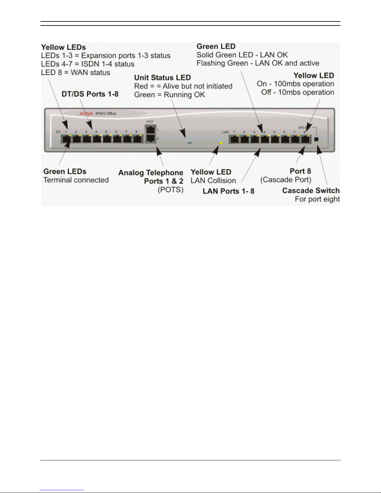
IP403 Office - Front View
• DS Ports
DS ports support Avaya 24xx, 44xx, 54xx and 64xx series telephones. These ports support either
A-Law or mu-Law PCM encoding (default is country dependant and can be switched in software refer to the Administration Manager Manual for details). Using standard structured wiring, these
RJ45 ports can be extended to the required telephone location. When telephones are equipped
with line cords that terminate in RJ11 plugs then, although their wiring is compatible, it is
advisable to use pin-to-pin RJ11/RJ45 adapters.
• Plain Ordinary Telephone (POTS) Ports
These two ports are used for connection to standard analog telephones, fax machines and
modems. They must not be connect to trunks. Using standard structured wiring, these RJ45
ports can be extended to the required telephone location. Converters can be used to provide BT
New Plan sockets (431A/631A) if required. When devices are equipped with line cords that
terminate in RJ11 plugs, then pin-to-pin RJ11/RJ45 adapters should be used.
• LAN Ports
The eight auto-negotiating 10/100 BaseT LAN hub ports are used for PC and server connectivity.
They can also be used to connect to the optional IP400 WAN3 Expansion Module and IP
telephones. LAN ports allow information relating to incoming and outgoing telephone calls to be
forwarded to PC based applications. They also provide access to the router
functionality/configuration of the IP403 Office platform for both data and Voice over IP (VoIP)
calls. (Where IP telephony is required, a suitable switch LAN switch with QoS capabilities.) This
eight port auto-negotiating 10/100 BaseT LAN hub has a single MAC address (printed on the
base of the unit). Where more than eight LAN connections are required, the eighth LAN port can
be used for cascading to other hubs. The Uplink push button to the right of this port is used to
set the mode. When the Uplink switch is in the out position the port can be connected to another
hub without the need for a crossover cable, i.e. the port is an MDI type port. When the Uplink
switch is in the in position the port can be connected directly to a PC.
• Cables
IP403 Office DS PRI 24 T1 are supplied with one red CAT5E cable. IP403 Office DS Analog 4
are supplied with four red CAT5E cables. For Port Pinouts and Cables, refer to Port Pinouts and
Cables respectively.
IP403 Office Platform
Installation Manual Page 11
IP Office 3.0 40DHB0002UKCL Issue 12c (24th February 2005)
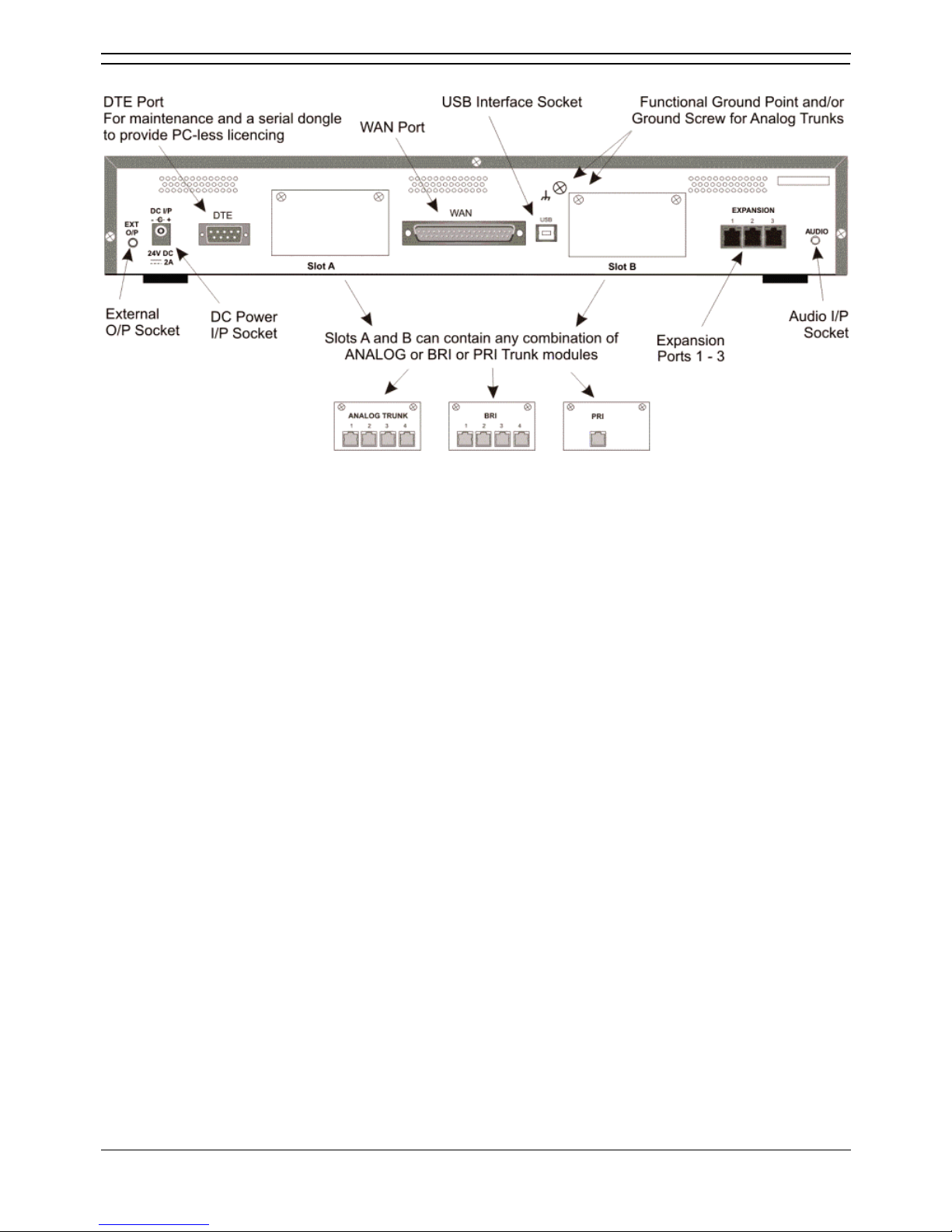
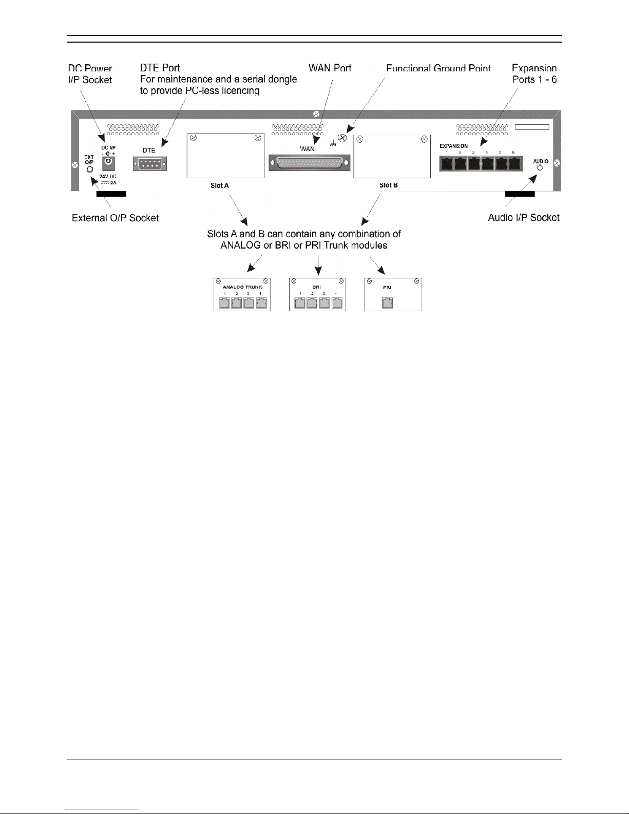
IP403 Office - Rear View
• External O/P Socket
Two relay ports that allow externally powered circuits to be controlled via a single 3.5mm stereo
jack socket.
• DC Power I/P Socket
Socket for the external 24V DC unregulated power supply (supplied with equipment).
• DTE Port
A 25-way D-type socket. Used for connection to PCs, servers and EFTPOS devices or terminals.
• Slot A/Slot B: BRI/PRI/ALOG Ports
The trunk interface modules are fitted into either Slots A or B and can consist of any combination
of:
• Quad Analog - 4 trunks. See Functional Ground
• PRI E1/PRI E1-R2: 30 trunks.
• PRI T1: 24B trunks or 23B+1D trunks.
PRI T1 trunks support both ISDN and Analog emulation. The default setting is 23B+1D
and is switchable in the installation software to provide 24B trunks.
• Quad BRI: 8 trunks.
• WAN Port
This port supports a single synchronous data connection, which can be X.21, V.35 or V.24. The
selection of the required interface is automatically determined from the pin-out of the cable
plugged into the 'WAN' port. This cable must be connected before power is applied for auto
detection to work. Connection to a Digital Leased Circuit is made by connecting the WAN port on
the rear of the unit to the existing Network Terminating Unit (NTU) via the appropriate X.21, V.35
or V.24 cable. This interface is identical to those on the WAN3 Expansion Module.
• USB Interface: Not used.
• Expansion Ports 1-3: Used to provide access to the optional Expansion Modules which allow
the IP403 Office to be expanded to 100 extensions.
• Audio I/P Socket: A single 3.5mm stereo or mono jack socket that enables input from an
external 'Music-on-Hold' source.
IP Office Installation
Installation Manual Page 12
IP Office 3.0 40DHB0002UKCL Issue 12c (24th February 2005)
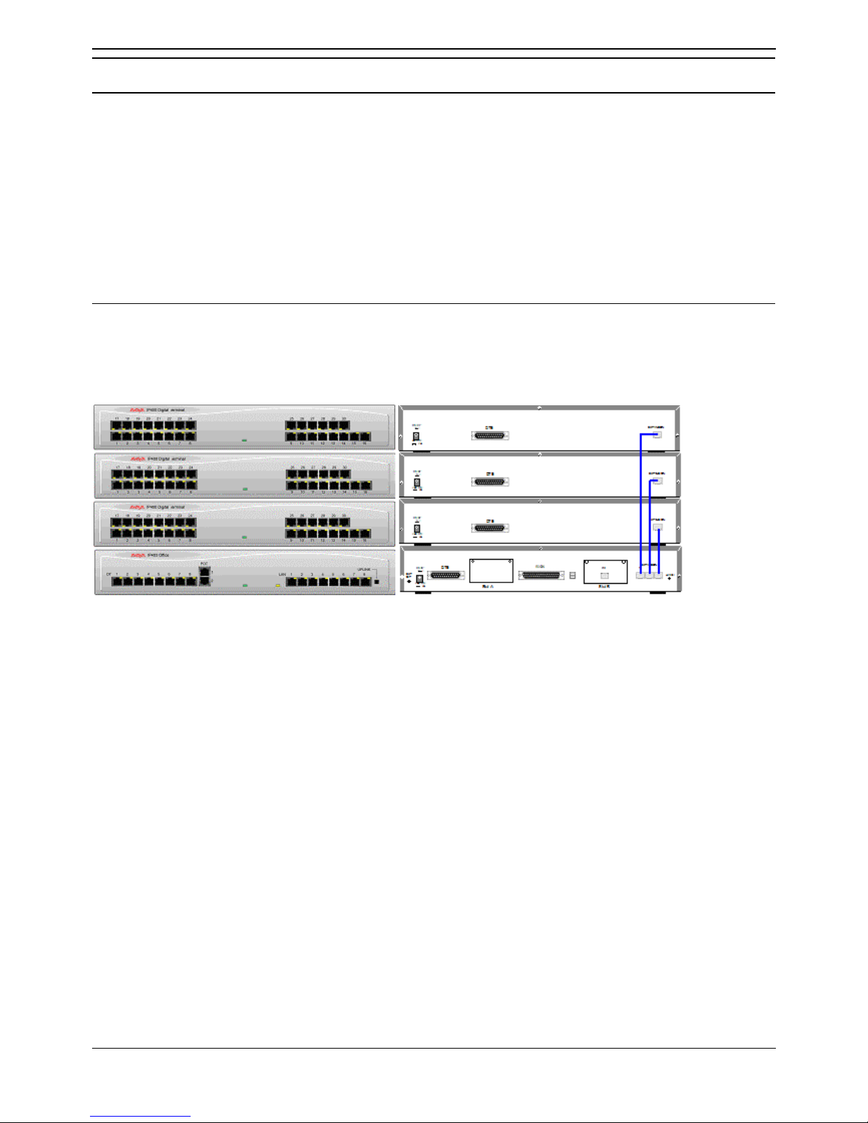
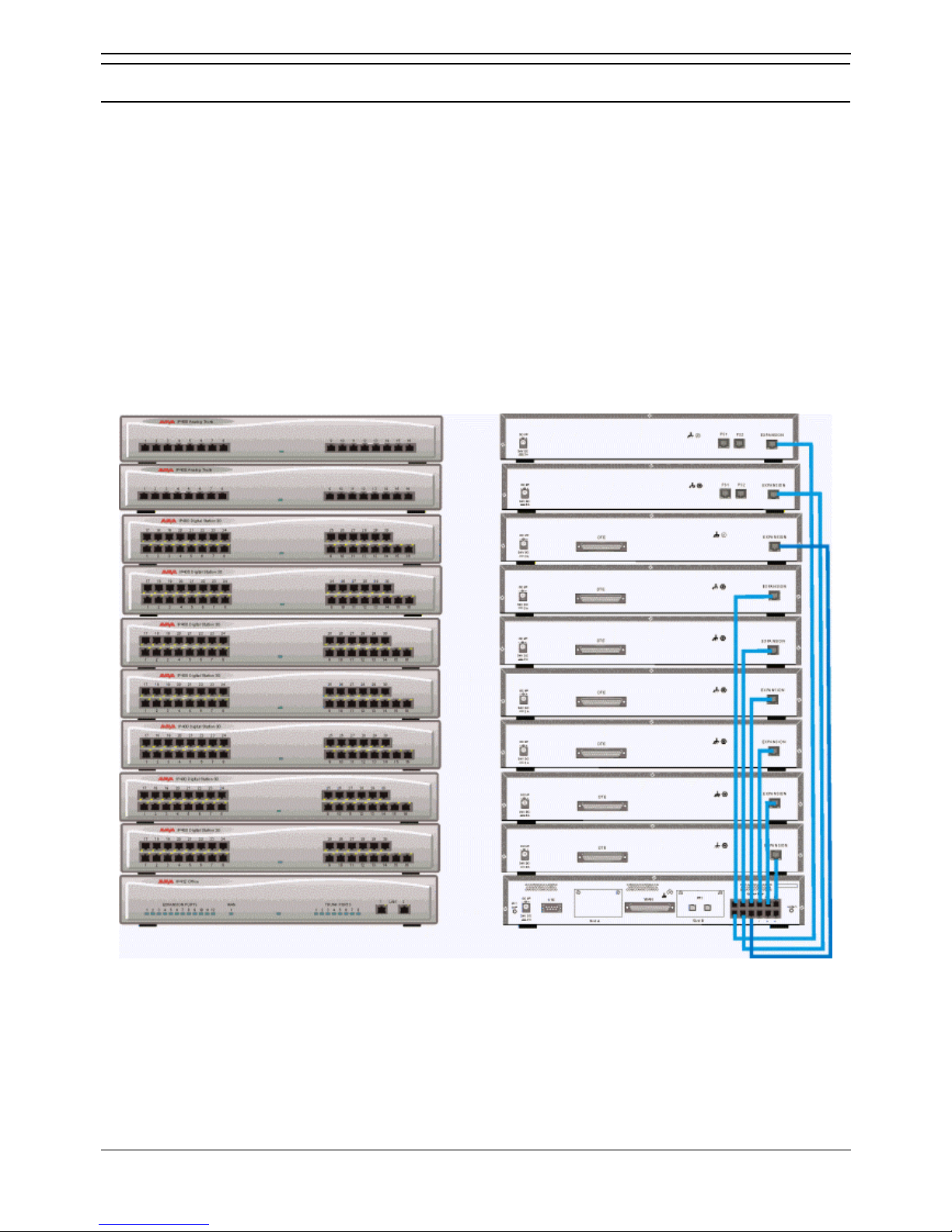
IP403 Typical Configuration
Scenario
A customer with sophisticated telephony requirements, needing 30 exchange lines and 80 Display
Stations.
This configuration provides support for 98 Avaya 5400 Series digital stations (18 spare for growth) and a
single Primary Rate ISDN connection. If growth beyond 18 users or additional line capacity were
anticipated, the IP406 V2 Office would be considered more appropriate.
Typically, a business of this size would have a data network built using LAN switches such as the Avaya
Cajun range. The IP403 Office would be connected to the data network through its integral 8 port Hub,
providing all users access to the Internet and IP Office productivity applications.
Kit List
• IP403 Office DS PRI 30 E1
• 3 x IP400 Digital Station Module 30
• 80 x Avaya 5400 Series telephones.

Installation Manual Page 13
IP Office 3.0 40DHB0002UKCL Issue 12c (24th February 2005)
IP406 Office V2 Platform
IP406 V2 Office
The IP406 V2 Office base unit, running software level 3.0+, supports up to 190 extensions by using the
ten built in ports and up to 6 Expansion Modules. The IP406 V2 Office base unit is equipped with DS
ports that support Avaya 24xx, 44xx, 54xx and 64xx telephones. These ports can be set for either muLaw or A-Law PCM encoding. At default DS ports are set to mu-Law. However, these can be switched in
software (refer to the Administration Manager Manual for details).
Connection to trunks is via up to two of the following integral interface modules:-
• Single or dual* PRI E1/PRI E1-R2 (30 or 60 trunks).
• Single or dual* PRI T1 (23B+1D or 24B trunks - USA only).
• (*dual PRI modules are only fitted to Slot A).
• Quad BRI (8 trunks).
• Analog 4 (loop start).
Eight LAN 10/100Mbps full duplex Layer 2 Ethernet switches and are used for PC and server
connectivity. They can also be used to connect to IP telephones (Avaya 46xx/56xx IP series). Power
over Ethernet is not provided by IP Office. The MAC address table can support up to 4000 devices.
Expansion Modules
Optional Expansion Modules allow the IP406 V2 Office to be expanded to 190 extensions. These
modules (except the WAN3 module – see below) are connected via the Expansion Port sockets that are
located on the back of each unit.
Up to six, in any combination, of the following Expansion Modules can be supported by the IP406 V2
Office base unit.
• IP400 Digital Station 16/30:
Two variants of 16 or 30 extensions for digital stations. Hence, six IP400 Digital Terminal/Station
30s will allow for a further 180 extensions which, with the 10 built in ports, makes a maximum of
190 extensions.
• IP400 Phone 8/16/30:
Three variants (8, 16 or 30 extensions) for analog telephones.
Hence, six IP400 Phone 30s will allow for a further 180 digital extensions which, with the 2 built in
ports, makes a maximum of 182 extensions.
• IP400 So8:
An S-bus module that provides 8 Basic rate ISDN interfaces.
• IP400 WAN3:
Provides support for a further 3 digital leased line (WAN) connections. These expansion modules
are connected to the IP406 V2 Office unit via one of the LAN Ports located on the front of each
unit.
• IP400 Analog Trunk 16:
Provides support for up to 16 Loop Start or Ground Start analog trunks. Two power fail sockets
are also provided.
Integral Modules (Optional)
In addition the IP406 V2 Office can be fitted with either or both of the following optional Integral Modules:
• Voice Compression Module (VCM)
Supports VoIP applications including trunking and support for IP telephones. Available in 5, 10
and 20 channel variants.
• Modem Modules
• Dual Modem Module:
Allows termination of two simultaneous analog modem calls up to and including 56kbps
(V90).
• Internal Modem Module:
Allows termination of up to 12 simultaneous analog modem calls up to and including
56kbps (V90).
IP Office Installation
Installation Manual Page 14
IP Office 3.0 40DHB0002UKCL Issue 12c (24th February 2005)
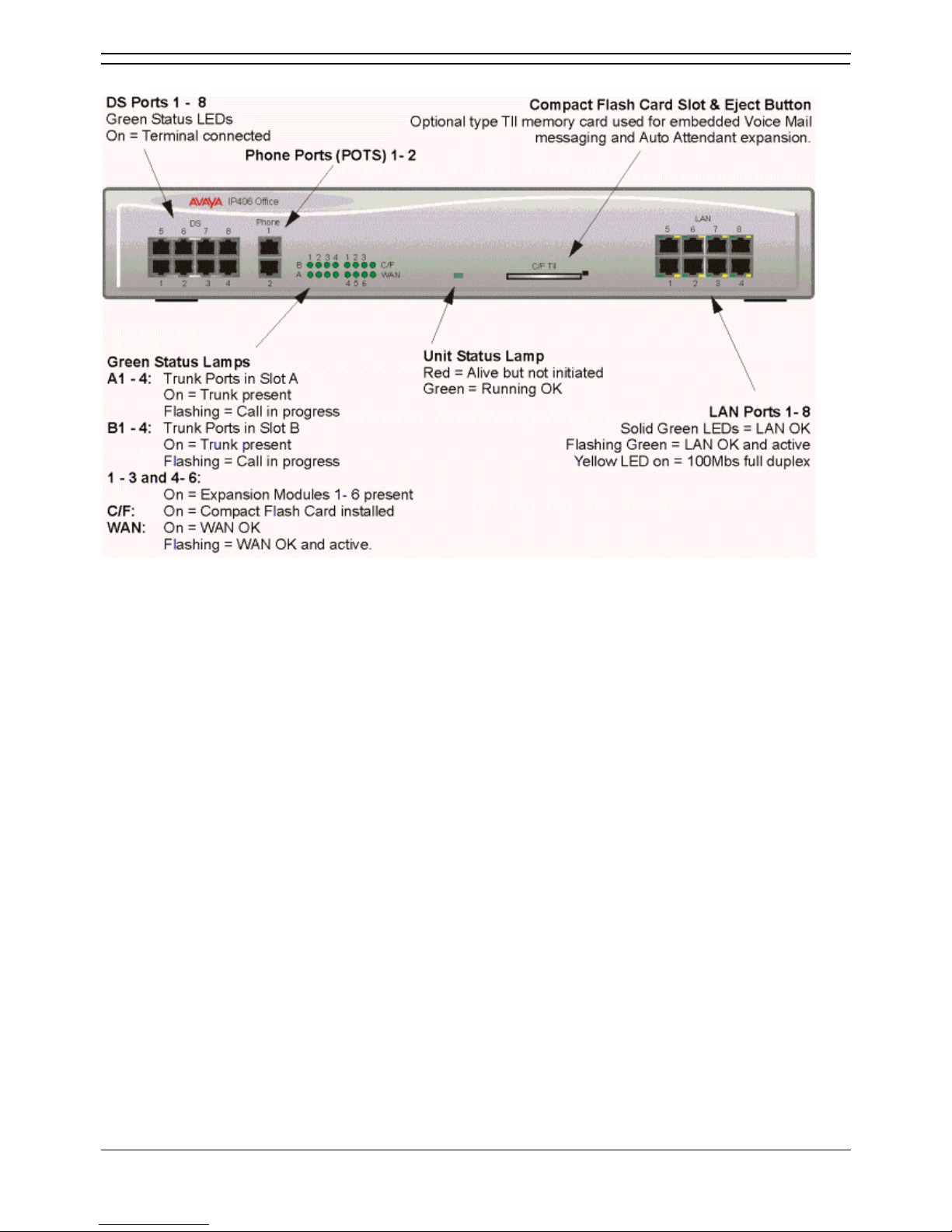
IP406 V2 Office - Front View
• DS Ports:
DS ports support Avaya 24xx, 44xx, 54xx and 64xx telephones. These ports support either ALaw or mu-Law PCM encoding (default is country dependant and can be switched in software).
Using standard structured wiring, these RJ45 ports can be extended to the required telephone
location. When telephones are equipped with line cords that terminate in RJ11 plugs then,
although their wiring is compatible, it is advisable to use pin-to-pin RJ11/RJ45 adapters.
• Phone Ports:
These ports are used for connection to standard analog telephones, fax machines, modems and
only support 2-wire connection. Using standard structured wiring, these RJ45 ports can be
extended to the required telephone location. When telephones are equipped with line cords that
terminate in RJ11 plugs then, although their wiring is compatible, it is advisable to use pin-to-pin
RJ11/RJ45 adapters.
• LAN Ports:
These are LAN 10/100Mbps full duplex Layer 2 Ethernet ports and are used for PC and server
connectivity. They have auto-sensing capability (MDI/MDIX) and hence avoid the need for LAN
crossover cables when connecting to a network. They can also be used to connect to IP
telephones (Avaya 4600 IP series). LAN ports allow information relating to incoming and outgoing
telephone calls to be forwarded to PC based applications. They also provide access to the router
functionality/configuration of the Avaya IP406 V2 Office V2 for both data and Voice over IP (VoIP)
calls.
• Cables
IP406 V2 Office PRI 30 E1 & PRI 24 T1 are supplied with one red CAT5E cable. IP406 V2 Office
Analog 4 is supplied with four red CAT5E cables. IP406 V2 Office BRI 16 is supplied with eight
red CAT5E cables.
IP412 Office Platform
Installation Manual Page 15
IP Office 3.0 40DHB0002UKCL Issue 12c (24th February 2005)
IP406 V2 Office - Rear View
• External O/P Socket:
Two relay ports that allow externally powered circuits to be controlled via a single 3.5mm stereo
jack socket.
• DC Power I/P Socket:
Socket for the external 24V DC regulated power supply (supplied with kit).
• DTE Port:
A 9-way D-type socket. Used for maintenance, serial dongle, connection to PCs, servers and
EFTPOS terminals.
• BRI/PRI/ALOG Ports:
The trunk interface modules are fitted into either Slots A or B and can consist of any combination
of:
• Quad Analog: 4 trunks
• PRI E1/PRI E1-R2: 30 trunks
• PRI J1: 24 trunks
• PRI T1: 24B trunks or 23B+1D trunks.
PRI T1 trunks support both ISDN and Analog emulation. The default setting is 23B+1D
and is switchable in the installation software to provide 24B trunks.
• Quad BRI: 8 trunks.
• WAN Port:
This port supports a single synchronous data connection, which can be X.21, V.35 or V.24. The
selection of the required interface is automatically determined from the pin-out of the cable
plugged into the ‘WAN’ port. This cable must be connected before power is applied for auto
detection to work. Connection to a Digital Leased Circuit is made by connecting the WAN port on
the rear of the unit to the existing Network Terminating Unit (NTU) via the appropriate X.21, V.35
or V.24 cable. These interfaces are identical to those on the IP400 WAN3.
• Expansion Ports 1-6:
Used to provide access to the optional Expansion Modules (see Expansion Modules Introduction) which allow the IP406 V2 Office to be expanded by a further 180 extensions to
make a maximum of 190 extensions.
• Audio I/P Socket:
A single 3.5mm stereo or mono jack socket that enables input from an external 'Music-on-Hold'
source.
IP Office Installation
Installation Manual Page 16
IP Office 3.0 40DHB0002UKCL Issue 12c (24th February 2005)
Typical Configurations
Scenario 1
A business requiring 60 analog Telephones and 16 Basic Rate ISDN lines (16 channels).
The IP406 V2 Office with two IP400 Office Phone 30 modules and two BRI 8 cards provides the required
line and extension capacity. Through the use of Phone Manager Lite the functionality provided by the
Analog Telephones is greatly enhanced. The expansion capability for an additional 4 Modules allows
the system to be expanded to a full 190 extensions. Additional lines can be added by replacing one of
the BRI interfaces for a Primary rate.
Kit List
• IP406 V2 Office with two BRI 8 cards.
• 2 x IP400 Office Phone Module 30.
Scenario 2
A business requiring 180 analog Telephones and 60 lines.
The configuration illustrates a fully configured IP406 Office providing 180 extensions and 60 trunks.
Factory shipped with a single PRI the system is fitted with an extra trunk card in its spare slot to provide
the additional 30 lines.
Kit List
• IP406 V2 Office PRI 30 E1 fitted with an additional IP400 IP PRI E1 trunk card.
• 6 x IP400 Office Phone Module 30.

IP412 Office Platform
Installation Manual Page 17
IP Office 3.0 40DHB0002UKCL Issue 12c (24th February 2005)
IP412 Office Platform
IP412 Office
The IP412 Office base unit, running software level 3.0+, supports up to 360 extensions by using up to 12
Expansion modules. Connection to trunks is via a combination of any of the following integral interface
modules:-
• Single or Dual* PRI E1/PRIE1-R2 (30 or 60 trunks respectively).
• Single or Dual* PRI T1 (24 or 48 trunks respectively - USA only).
• (*dual PRIs can be fitted to either Slots A or B).
• Quad BRI (8 trunks) .
• Analog 4 (4 loop start trunks).
Dual independent auto-negotiating 10/100 Base-TX Ethernet ports provide segmented access (allows a
firewall break to be used) to the LAN.
(Where IP telephones are to be used a suitable LAN switch with QoS capabilities, must be used.)
Expansion Modules
Optional Expansion Modules allow the IP412 Office to be expanded to a maximum of 360 digital or
analog extensions. The Expansion Modules (with the exception of the WAN3 – see below) are
connected via the Expansion Port sockets that are located on the back of each unit.
Up to twelve, in any combination, of the following Expansion Modules can be supported by the IP412
Office base unit provided that the maximum number of extensions does not exceed 360.
• IP400 Digital Station 16/30
Two variants of 16 or 30 extensions for digital telephones. Hence, twelve IP400 Digital
Terminal/Station modules can be fitted to allow a maximum of 360 digital extensions.
• IP400 Phone 8/16/30
Three variants (for 8, 16 or 30 extensions) for analog telephones. Hence, twelve IP400 Phone
modules can be fitted to allow a maximum of 360 analog extensions.
• IP400 So8
An S-bus module that provides 8 Basic rate ISDN interfaces.
• IP400 WAN3
Provides support for a further 3 digital leased line (WAN) connections. These expansion modules
are connected to the IP403 Office unit via one of the LAN Ports located on the front of each unit.
• IP400 Analog Trunk 16
Provides support for up to 16 Loop Start or Ground Start analog trunks. Two power fail sockets
are also provided.
Integral Modules (Optional)
In addition the IP412 Office can be fitted with either or both of the following optional Integral Modules:
• Voice Compression Module (VCM)
Provides VoIP applications (including trunking) and support for IP telephones. Available in 5, 10,
20 and 30 channel variants. The IP412 Office supports two VCMs of any type.
• Modem Modules
• Dual Modem Module:
Allows termination of two simultaneous analog modem calls up to and including 56kbps
(V90).
• Internal Modem Module:
Allows termination of up to 12 simultaneous analog modem calls up to and including
56kbps (V90).
IP Office Installation
Installation Manual Page 18
IP Office 3.0 40DHB0002UKCL Issue 12c (24th February 2005)
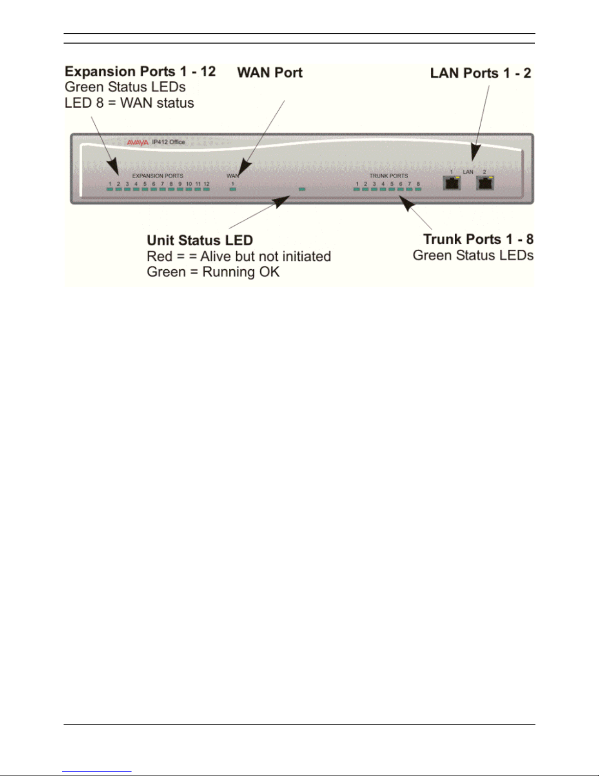
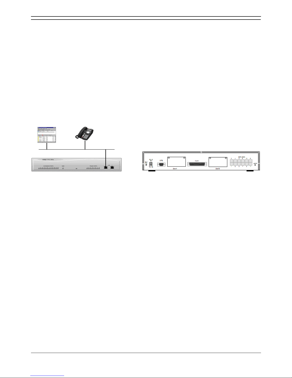
IP412 Office - Front View
• LAN Ports
The segmented dual independent auto-negotiating 10/100 BaseT Ethernet ports are used for PC
and server connectivity. They can also be used to connect to the optional IP400 WAN3
Expansion Module and IP telephones. See IP400 WAN3. Information relating to incoming and
outgoing telephone calls can be forwarded to PC based applications via these ports. These
segmented Ethernet ports support separate IP and MAC addresses and hence a Firewall break
may be implemented. They also provide access to the router functionality/configuration of the
IP412 Office platform for both data and Voice over IP (VoIP) calls.
• Cables
IP412 Office DS PRI 24 T1 are supplied with one red CAT5E cable.
IP412 Office Platform
Installation Manual Page 19
IP Office 3.0 40DHB0002UKCL Issue 12c (24th February 2005)
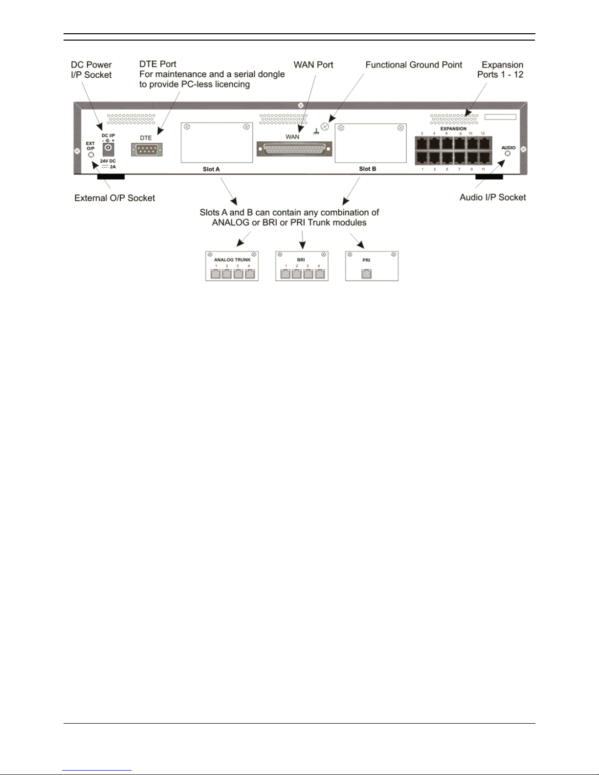
IP412 Office - Rear View
• External O/P Socket
Two relay ports that allow externally powered circuits to be controlled via a single 3.5mm stereo
jack socket.
• DC Power I/P Socket
Socket for the external 24V DC unregulated power supply (supplied with kit).
• DTE Port
A 9-way D-type socket. Used for connection to PCs, servers and EFTPOS terminals.
• BRI/PRI/ALOG Ports
TThe trunk interface modules are fitted into either Slots A or B and can consist of any
combination of:
• Quad Analog: 4 trunks.
• Quad BRI: 8 trunks.
• Single PRI E1/E1-R2: 30 trunks.
PRI T1trunks support both ISDN and Analog emulation. The default setting is 23B+1D (46B+2D)
and is switchable in the installation software to become a 24B (48B) trunk.
• WAN Port
This port supports a single synchronous data connection, which can be X.21, V.35 or V.24. The
selection of the required interface is automatically determined from the pin-out of the cable
plugged into the WAN port. This cable must be connected before power is applied for auto
detection to work. Connection to a Digital Leased Circuit is made by connecting the WAN port on
the rear of the unit to the supplied Network Terminating Unit (NTU) via the appropriate X.21/V.35
/V.24 cable. This interface is identical to those on the WAN3 Expansion Module.
• Expansion Ports 1-12
Used to provide access to either optional Expansion Modules which allow the IP412 Office to be
expanded to 256 extensions or additional WAN interfaces.
• Audio I/P Socket
A single 3.5mm stereo or mono jack socket that enables input from an external 'Music-on-Hold'
source.
IP Office Installation
Installation Manual Page 20
IP Office 3.0 40DHB0002UKCL Issue 12c (24th February 2005)
Typical Configurations
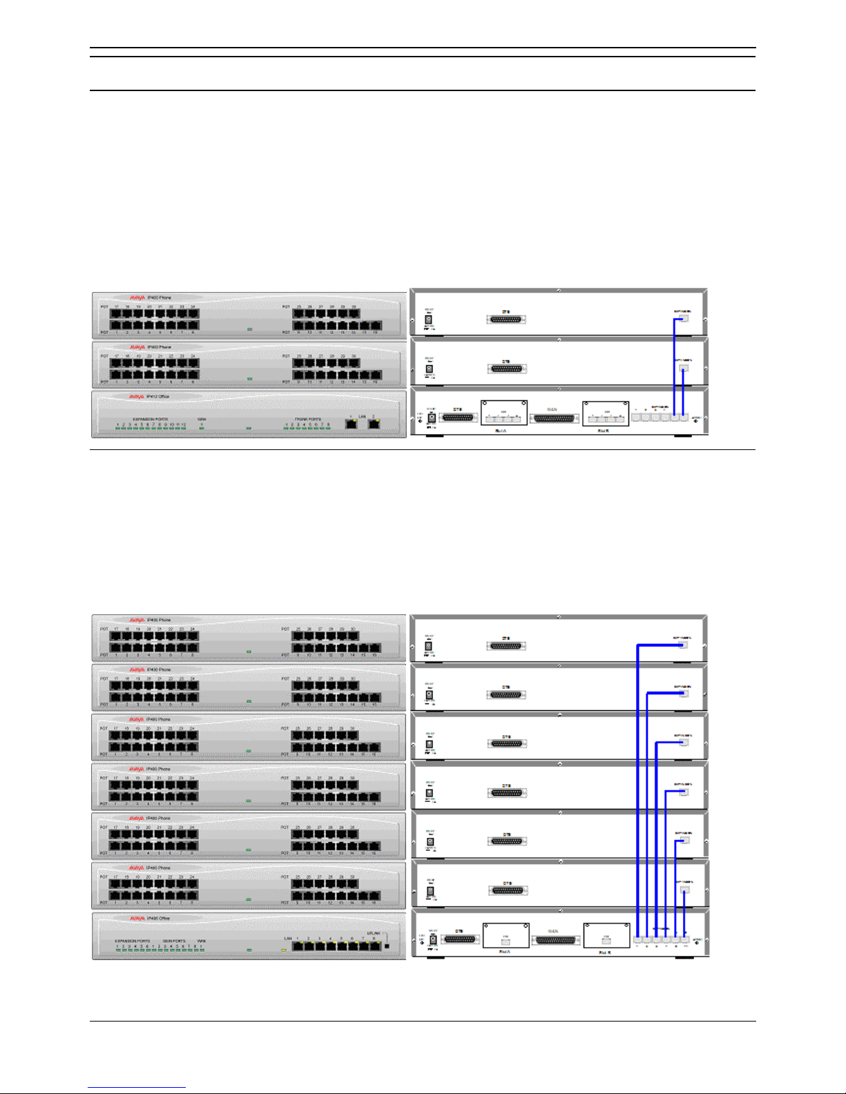
IP412 Scenario 1
A business requiring 210 Display Telephones and 96 Digital lines with 20 Analog lines for fall back
purposes in the event of the T1 service failing.
The configuration illustrates a fully configured IP412 Office providing 210 extensions and 96 digital
trunks (4 x T1) and two IP400 Office Analog Trunk 16 modules offering capacity of up to 32 analog trunk
lines. Factory shipped with a single Dual PRI T1 interface, the system is fitted with an extra trunk card in
its spare slot to provide the additional 48 lines. If the system requires expansion, a further five expansion
modules can be added.
Kit List
• IP412 Office PRI 48 T1.
• 7 X IP400 Office Digital Station 30 Module.
• 2 x IP400 Office Analog Trunk 16.
• 210 x Avaya 54102 Digital Terminals.
IP412 Office Platform
Installation Manual Page 21
IP Office 3.0 40DHB0002UKCL Issue 12c (24th February 2005)
IP412 Scenario 2
A Business requiring 90 IP hardphones, 90 IP softphones and 60 lines.
This configuration illustrates an IP412 Office PRI 60 E1 fitted with two optional IP400 Office Voice
Compression Module 20s. These two internally fitted cards allow up 40 simultaneous calls to external
parties, as they are only used when an IP extension is calling a non-IP telephone or line. If less
‘Gateway’ed calls are required, one of the 20 channel cards could be substituted for a smaller variant.
The IP Office softphone is ‘Phone Manager PC Softphone’ which requires two types of Licence Keys
which allow Phone Manager Lite, supplied as standard, to run as IP Extensions.
Kit List
• IP412 Office PRI 60 E1 fitted with two optional IP400 Voice Compression Module 20s.
• 90 x 5610 IP Hardphones.
• IP400 Phone Manager Pro RFA unlimited.
• IP400 Phone Manager PC Softphone RFA 50.
• IP400iPhone Manager PC Softphone RFA 40 (50+40 = 90)).


Installation Manual Page 23
IP Office 3.0 40DHB0002UKCL Issue 12c (24th February 2005)
Expansion Modules
Introduction
Dependent upon configuration requirements, combinations of the following Expansion Modules are used
with IP Office platforms. With the exception of the WAN3 module, all of these Expansion Modules are
connected to the Expansion Ports of an IP Office platform using Expansion Interconnect Cables.
• IP400 Digital Stations 16/30
• IP400 Phone 8/16/30
• IP400 So8
• IP400 WAN3
• IP400 Analog Trunk 16
IP Office Installation
Installation Manual Page 24
IP Office 3.0 40DHB0002UKCL Issue 12c (24th February 2005)
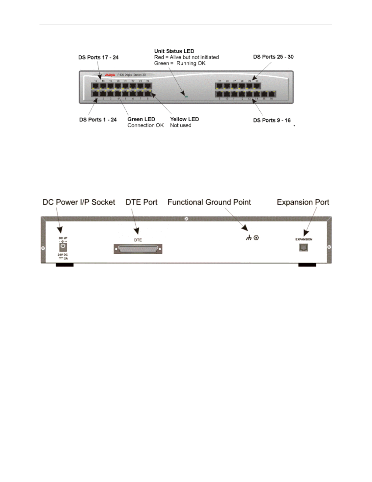
IP400 Digital Stations 16/30
Front View (30 Port version)
• DS ports support Avaya 24xx, 54xx, 64xx and/or 44xx series telephones (see page 5). These
ports support either A-Law or mu-Law PCM encoding (default is country dependant and can be
switched in software - refer to the Administration Manager Manual for details). Using standard
structured wiring, these RJ45 ports can be extended to the required telephone location. When
telephones are equipped with line cords that terminate in RJ11 plugs then, although their wiring is
compatible, it is advisable to use pin-to-pin RJ11/RJ45 adapters.
Rear View
• Expansion Port
Used to connect a Phone Expansion Module to the Expansion Ports of an IP Office platform.
• DC Power I/P Socket
Socket for the external 24V DC unregulated power supply (supplied with kit).
• DTE Port
A 25-way D-type socket. Used for connection to PC (diagnostics only).
All IP400 Office Digital Station variants are supplied with one blue Expansion Interconnect cable. See
Expansion Interconnect Cable and Port Pinouts.
Expansion Modules
Installation Manual Page 25
IP Office 3.0 40DHB0002UKCL Issue 12c (24th February 2005)
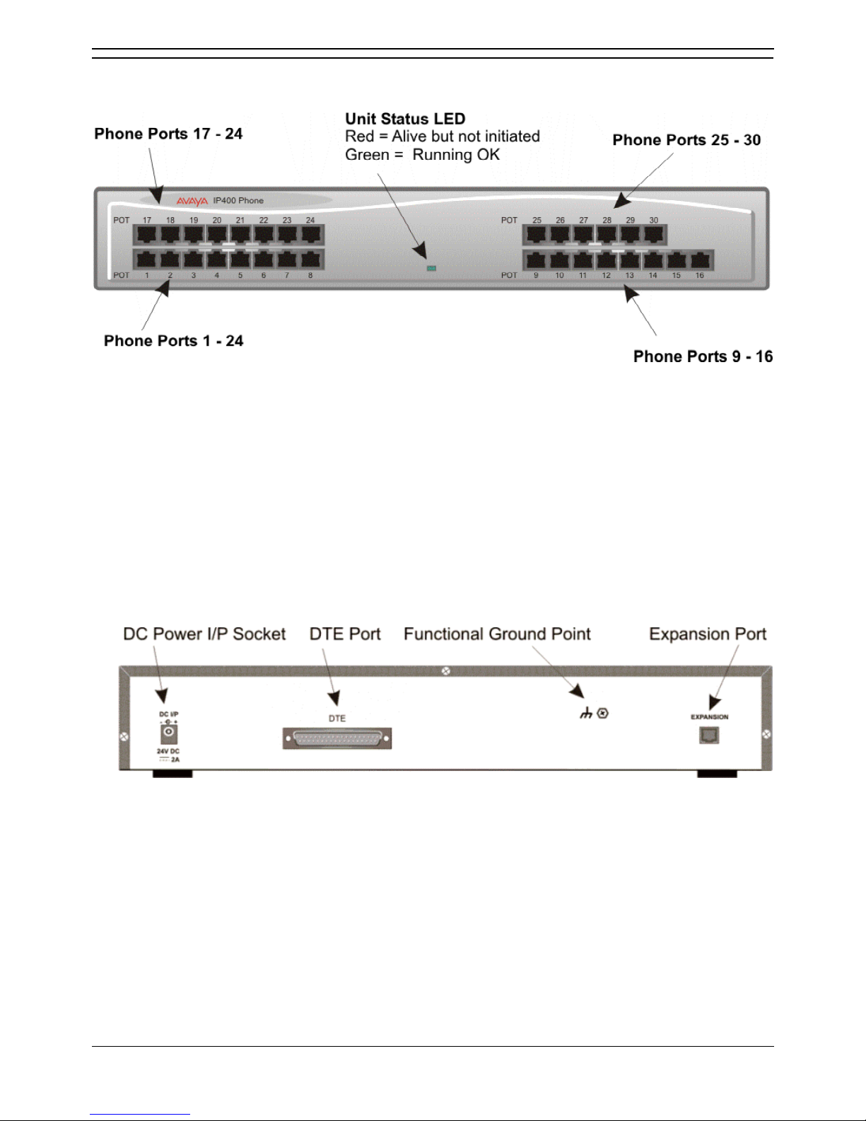
IP400 Phone 8/16/30
Front View (30 Port version)
Notes
1. The IP400 Phone 8 variant is only equipped with the bottom left row of ports.
2. The IP400 Phone 16 variant is only equipped with the bottom row of ports.
• Plain Ordinary Telephone (POT) Ports
These ports are used for connection to standard analog telephones, fax machines and modems.
Using standard structured wiring, these RJ45 ports can be extended to the required telephone
location. Converters can be used to provide BT New Plan sockets (431A/631A) if required. When
devices are equipped with line cords that terminate in RJ11 plugs, then RJ11/RJ45 adapters
should be used. All analog telephones must conform to the port specification (see Interfaces).
Rear View (all versions)
• Expansion Port
Used to connect a Phone Expansion Module to the Expansion Ports of an IP Office platform.
• DC Power I/P Socket
Socket for the external 24V DC unregulated power supply (supplied with kit).
• DTE Port
A 25-way D-type socket. Used for connection to PC (diagnostics only).
All IP400 Office Phone variants are supplied with one blue Expansion Interconnect cable. See
Expansion Interconnect Cable and Port Pinouts.
IP Office Installation
Installation Manual Page 26
IP Office 3.0 40DHB0002UKCL Issue 12c (24th February 2005)
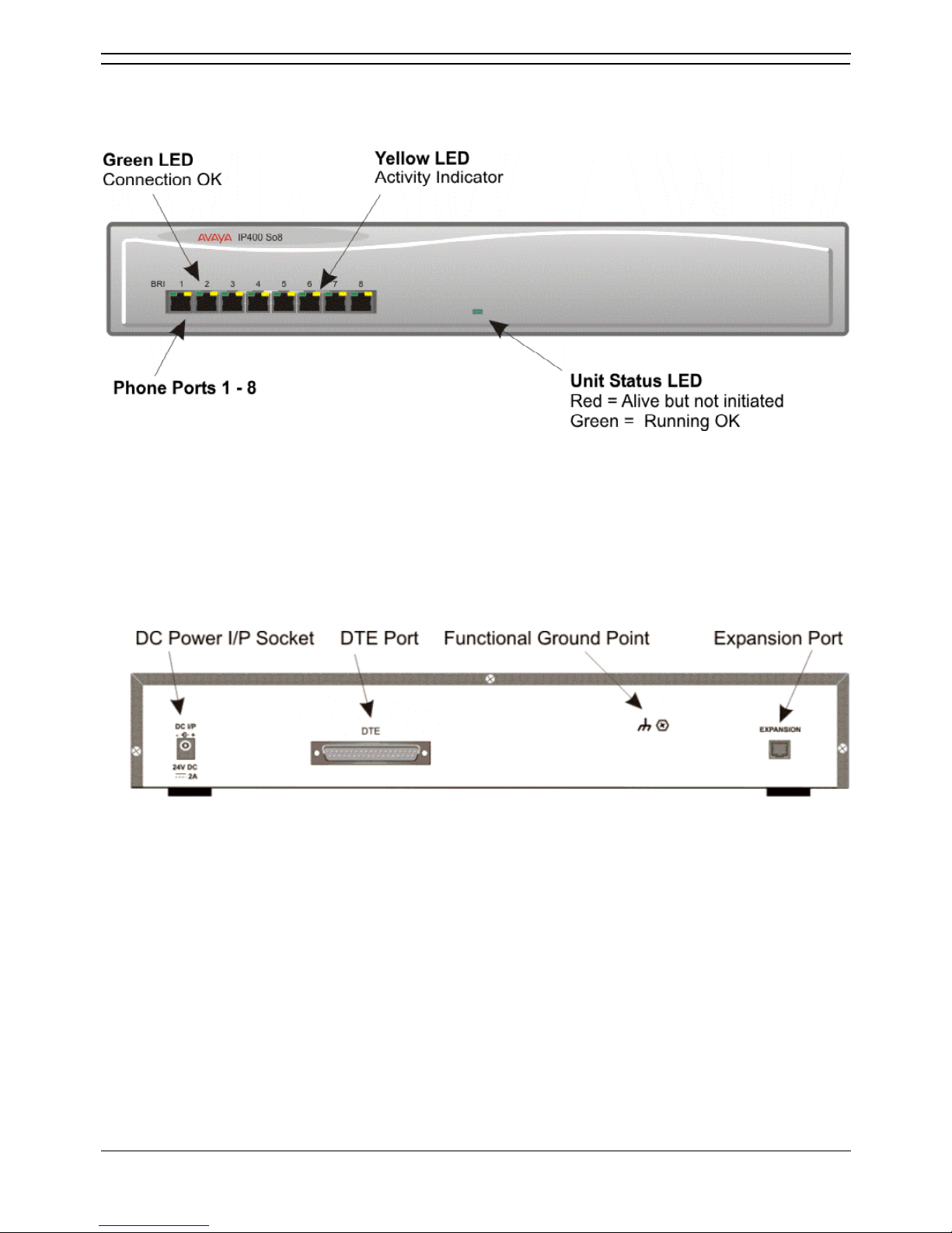
IP400 So8
The So8 Module is only applicable to countries that support the ETSI signaling protocol.
Front View
• BRI Ports
These are 64k ISDN BRI S-Bus ports and are used for connection to ISDN Telephones, Group 4
faxes, Video conferencing units, etc.
• WARNING:
BRI phone ports must not be connected to the external ISDN Connections.
Rear View
• Expansion Port
Used to connect a So8 Module to the Expansion Ports of an IP Office platform.
• DC Power I/P Socket
Socket for the external 24V DC unregulated power supply (supplied with kit).
• DTE Port
A 25-way D-type socket. Used for connection to PC (as a diagnostic aid).
IP400 So8 is supplied with one blue Expansion Interconnect cable. See Expansion Interconnect Cable
and Port Pinouts.
Expansion Modules
Installation Manual Page 27
IP Office 3.0 40DHB0002UKCL Issue 12c (24th February 2005)
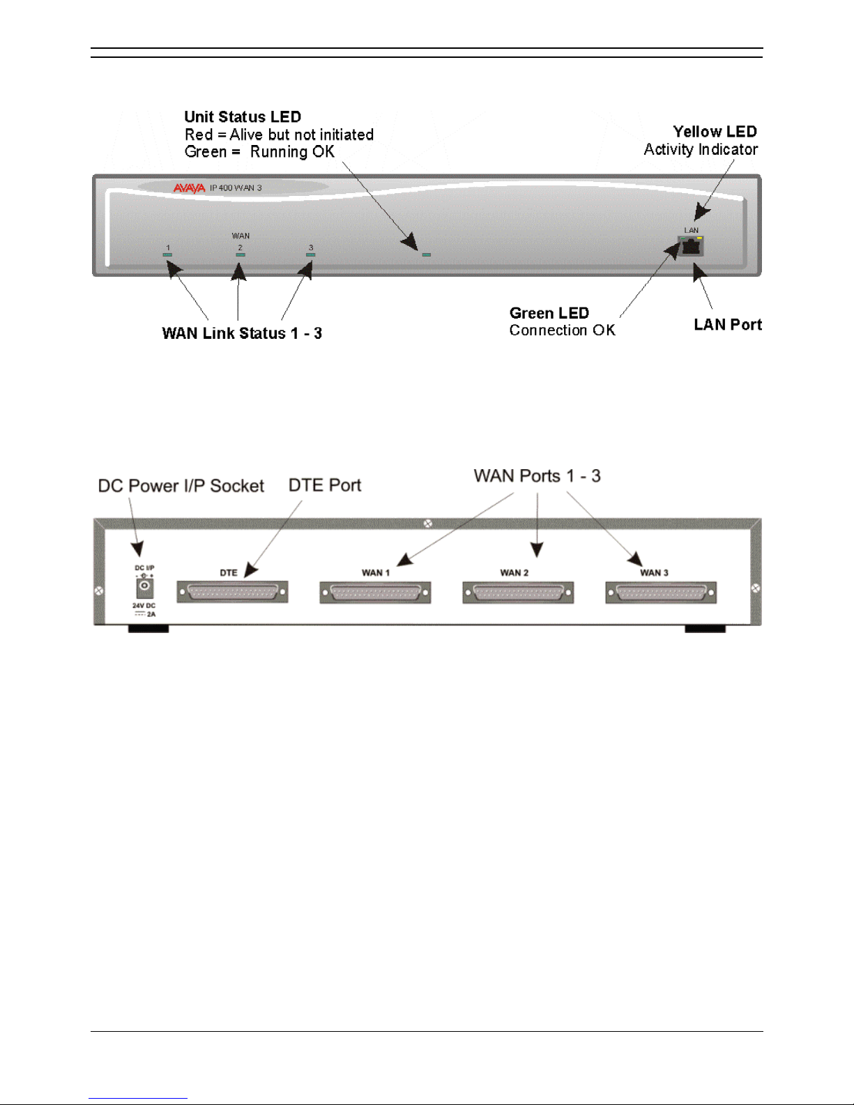
IP400 WAN3
Front View
• LAN Port
The LAN Port is the expansion port and permits connection to an IP403, IP406 or IP412 Office
platform LAN Port. A LAN Interconnect cable is required for connection to an IP403 or IP406. An
IP412 requires a LAN Crossover cable.
Rear View
• WAN Ports
These ports support a single synchronous data connection, which can be X.21, V.35 or
V.24/V.28. The selection of the required interface is automatically determined from the pin-out of
the cable plugged into the WAN port. This cable must be connected before power is applied for
auto detection to work. Connection to a Digital Leased Circuit is made by connecting the WAN
port on the rear of the unit to the existing Network Terminating Unit (NTU) via the appropriate
X.21, V.35 or V.24 cable. These WAN ports are identical to those on the IP403/406/412 control
units.
• DC Power I/P Socket
Socket for the external 24V DC unregulated power supply (supplied with kit).
• DTE Port
A 25-way D-type socket. Used for connection to PC (as a diagnostic aid).
IP400 WAN3 is supplied with one green LAN Interconnect cable. See LAN Interconnect Cable and Port
Pinouts.
IP Office Installation
Installation Manual Page 28
IP Office 3.0 40DHB0002UKCL Issue 12c (24th February 2005)
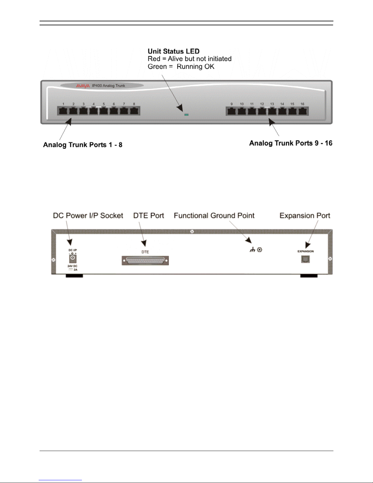
IP400 Analog Trunk 16
Front View
• Analog Trunk Ports
These ports are used for connection to standard analog trunks (loop start or ground start). Using
standard structured wiring, these RJ45 ports can be extended to the required trunk sockets.
Trunk ports 1 and 2 are, in the event of power failure, automatically switched to PF1 and PF2
respectively on the rear of the unit.
Rear View
• Expansion Port
Used to connect the Analog Trunk Expansion Module an Expansion Ports of an IP400 Office
platform.
• DC Power I/P Socket
Socket for the external 24V DC unregulated power supply (supplied with kit).
• Power Fail Trunks
These two ports must be set and connected to Loop Start trunks only. POTs plugged into these
two sockets are mapped to trunk ports 1 & 2 such that, in the event of a mains power failure, PF1
and PF2 can operate as 'hot lines' to the emergency services (eg. 911, etc).
• Protective Grounding Point
Within the USA a protective grounding must be permanently fitted. Connection of this protective
grounding requires the use of suitable tools and must be connected at both ends before
connection is made to the telecommunications network.
IP400 Analog Trunk 16 is supplied with one blue Expansion Interconnect cable. See Expansion
Interconnect Cable and Port Pinouts.

Installation Manual Page 29
IP Office 3.0 40DHB0002UKCL Issue 12c (24th February 2005)
Country Variants
Overview of Country Variants
The following are lists of the country variants for each IP400 Office platform, trunk module kits, Integral
module kits and expansion modules. The PCS level for each module can be found on a label that is
stuck to the base of each module.
Throughout this section the following abbreviations are used:
• All = Everywhere.
• CALA = Caribbean/Latin America.
• CH = China.
• EU = Europe.
• JP = Japan.
• KR = Korea.
• NA = North America (USA and/or Canada).
• NZ = New Zealand.
• ROW = Rest of world (all countries excluding USA, Canada).
For countries outside North America/ CALA, use ROW variant unless stated otherwise.

IP Office Installation
Installation Manual Page 30
IP Office 3.0 40DHB0002UKCL Issue 12c (24th February 2005)
IP400 Office Systems
IP403 Office
Variant A-Law/
Mu-Law
Country SAP Code
IP403 Office DS (No Trunks) Base A ROW/CALA 700234453
IP403 Office DS (No Trunks) Base Mu NA 700350390
IP403 Office DS PRI 24 T1 Base Mu NA 700184666
IP403 Office DS Analog 4 Base Mu NA 700184674
IP406 V2 Office
Variant A-Law/
Mu-Law
Country SAP Code
IP406 V2 Office DS (No Trunks) Base A ROW/CALA 700343536
IP406 V2 Office DS (No Trunks) Base A NA 700359946
IP406 V2 Office DS BRI 8 Base
Α
NA 700343478
IP406 V2 Office DS PRI 30 E1 Base
Α
NA 700343502
IP406 V2 Office DS PRI 24 T1 Base Mu NA 700359953
IP406 V2 Office DS Analog 4 Base Mu NA 700359961
IP412 Office
Variant A-Law/
Mu-Law
Country SAP Code
IP412 Office (No Trunks) Base A ROW/CALA 700234479
IP412 Office PRI 30 E1 Base A ROW but not CH, CALA 700184724
IP412 Office PRI 60 E1 Base A ROW but not CH, CALA 700184732
IP412 Office (No Trunks) Base Mu NA 700350408
IP412 Office PRI 24 T1 Base Mu NA 700184740
IP412 Office PRI 48 T1 Base Mu NA 700184757
IP Office Administration CD Set
This CD set is no longer supplied in the base unit box and must be ordered separately.
Variant Country SAP Code
IP Office Use/Admin CD Set ALL 700345879
 Loading...