


 Loading...
Installing and Configuring the
Avaya S8400 Media Server
Release 3.1
03-300678
Release 3.1
February 2006 Issue 1
© 2006 Avaya Inc.
All Rights Reserved.
Notice
While reasonable efforts were made to ensure that the information in this document was complete and accurate at the time of printing, Avaya Inc. can assume no liability for any errors. Changes and corrections to the information in this document may be incorporated in future releases.
For full legal page information, please see the complete document,
Avaya Legal Page for Hardware Documentation, document number 03-600759.
To locate this document on our Web site, simply go to http://www.avaya.com/support and search for the document number in the search box.
Documentation disclaimer
Avaya Inc. is not responsible for any modifications, additions, or deletions to the original published version of this documentation unless such modifications, additions, or deletions were performed by Avaya. Customer and/or End User agree to indemnify and hold harmless Avaya, Avaya's agents, servants and employees against all claims, lawsuits, demands and judgments arising out of, or in connection with, subsequent modifications, additions or deletions to this documentation to the extent made by the Customer or End User.
Link disclaimer
Avaya Inc. is not responsible for the contents or reliability of any linked Web sites referenced elsewhere within this documentation, and Avaya does not necessarily endorse the products, services, or information described or offered within them. We cannot guarantee that these links will work all of the time and we have no control over the availability of the linked pages.
Warranty
Avaya Inc. provides a limited warranty on this product. Refer to your sales agreement to establish the terms of the limited warranty. In addition, Avaya’s standard warranty language, as well as information regarding support for this product, while under warranty, is available through the following Web site: http://www.avaya.com/support.
Copyright
Except where expressly stated otherwise, the Product is protected by copyright and other laws respecting proprietary rights. Unauthorized reproduction, transfer, and or use can be a criminal, as well as a civil, offense under the applicable law.
Avaya support
Avaya provides a telephone number for you to use to report problems or to ask questions about your product. The support telephone number
is 1-800-242-2121 in the United States. For additional support telephone numbers, see the Avaya Web site: http://www.avaya.com/support.
Avaya - Proprietary. Use pursuant to the terms of your signed agreement or Avaya policy. DRAFT - December 19, 2005 - 12:11 PM
Contents
Chapter 1: Introduction . . . . . . . . . . . . . . . . . . . . . . . . . . . . . . . . . . |
7 |
Audience . . . . . . . . . . . . . . . . . . . . . . . . . . . . . . . . . . . . . . . . |
7 |
How to use this documentation . . . . . . . . . . . . . . . . . . . . . . . . . . . |
8 |
Pre-installation: before going on site . . . . . . . . . . . . . . . . . . . . . . . . |
9 |
Documentation. . . . . . . . . . . . . . . . . . . . . . . . . . . . . . . . . . . |
9 |
Verifying site readiness . . . . . . . . . . . . . . . . . . . . . . . . . . . . . . |
9 |
Laptop preparation, software, and system information. . . . . . . . . . . . . |
10 |
Copying files to the laptop . . . . . . . . . . . . . . . . . . . . . . . . . . . . |
10 |
About ASG and the unique on-site password . . . . . . . . . . . . . . . . . . |
11 |
Obtaining license and Avaya authentication files . . . . . . . . . . . . . . . . |
11 |
Pre-installation: at the site . . . . . . . . . . . . . . . . . . . . . . . . . . . . . . |
13 |
Equipment specifications . . . . . . . . . . . . . . . . . . . . . . . . . . . . . . . |
13 |
About media server port connections . . . . . . . . . . . . . . . . . . . . . . . . |
14 |
Ethernet ports . . . . . . . . . . . . . . . . . . . . . . . . . . . . . . . . . . . |
14 |
Media server cable adapter . . . . . . . . . . . . . . . . . . . . . . . . . . . . |
15 |
Ethernet connectivity with the TN8412AP circuit pack . . . . . . . . . . . . . |
16 |
Services access port . . . . . . . . . . . . . . . . . . . . . . . . . . . . . . . |
19 |
About Modem connections . . . . . . . . . . . . . . . . . . . . . . . . . . . . . |
20 |
About Media Gateways . . . . . . . . . . . . . . . . . . . . . . . . . . . . . . . . |
20 |
About Processor Ethernet . . . . . . . . . . . . . . . . . . . . . . . . . . . . . . |
21 |
About SSH . . . . . . . . . . . . . . . . . . . . . . . . . . . . . . . . . . . . . . . |
22 |
High level overview of installation process . . . . . . . . . . . . . . . . . . . . . |
23 |
Installing and cabling the media gateways . . . . . . . . . . . . . . . . . . . |
23 |
Installing Avaya Communication Manager. . . . . . . . . . . . . . . . . . . . |
23 |
Configuring the MPC . . . . . . . . . . . . . . . . . . . . . . . . . . . . . . . |
23 |
Configuring the media server . . . . . . . . . . . . . . . . . . . . . . . . . . . |
23 |
Translating the SIPI . . . . . . . . . . . . . . . . . . . . . . . . . . . . . . . . |
24 |
Completing the installation administration . . . . . . . . . . . . . . . . . . . |
24 |
Testing the finished installation . . . . . . . . . . . . . . . . . . . . . . . . . |
24 |
Chapter 2: SNMP Configuration . . . . . . . . . . . . . . . . . . . . . . . . . . . . . |
25 |
Configuration of the SNMP modules in the UPS . . . . . . . . . . . . . . . . . . |
25 |
Default UPS IP addresses . . . . . . . . . . . . . . . . . . . . . . . . . . . . . |
26 |
Preparing to configure the SNMP module . . . . . . . . . . . . . . . . . . . . |
26 |
Administering the SNMP module . . . . . . . . . . . . . . . . . . . . . . . . . |
27 |
Setting selected traps (alarming) . . . . . . . . . . . . . . . . . . . . . . . . |
28 |
Installing and Configuring the Avaya S8400 Media Server |
February 2006 3 |
Contents |
|
|
Chapter 3: Communication Manager Installation . . . . . . . . . . . . . . . . . . . . |
29 |
|
Clearing the ARP cache on the laptop . . . . . . . . . . . . . . . . . . . . . . . . |
29 |
|
Connecting the CD/DVD drive to the media server . . . . . . . . . . . . . . . . . |
30 |
|
Powering up the media server . . . . . . . . . . . . . . . . . . . . . . . . . . . . |
30 |
|
Accessing the media server . . . . . . . . . . . . . . . . . . . . . . . . . . . . . |
30 |
|
Configuring Telnet for Windows 2000/XP . . . . . . . . . . . . . . . . . . . . . . |
31 |
|
Installing Avaya Communication Manager . . . . . . . . . . . . . . . . . . . . . |
32 |
|
Installing IA 770 INTUITY AUDIX Messaging . . . . . . . . . . . . . . . . . . . . |
33 |
|
Chapter 4: Media server configuration . . . . . . . . . . . . . . . . . . . . . . . . . . |
35 |
|
Opening the Maintenance Web Interface. . . . . . . . . . . . . . . . . . . . . . . |
35 |
|
Copying files to the media server . . . . . . . . . . . . . . . . . . . . . . . . . . |
36 |
|
Enabling Network Time Servers . . . . . . . . . . . . . . . . . . . . . . . . . . . |
37 |
|
Using the Installation Wizard . . . . . . . . . . . . . . . . . . . . . . . . . . . . . |
38 |
|
Verifying MPC IP information . . . . . . . . . . . . . . . . . . . . . . . . . . . . . |
39 |
|
Installing MPC firmware . . . . . . . . . . . . . . . . . . . . . . . . . . . . . . . |
39 |
|
Verifying media server connection to the customer’s LAN (if provided) . . . . . |
40 |
|
Enabling firewall settings . . . . . . . . . . . . . . . . . . . . . . . . . . . . . . . |
40 |
|
Configuring the modem . . . . . . . . . . . . . . . . . . . . . . . . . . . . . . . |
41 |
|
Chapter 5: IP interface translations . . . . . . . . . . . . . . . . . . . . . . . . . . |
43 |
|
Starting SAT terminal emulation . . . . . . . . . . . . . . . . . . . . . . . . . . . |
44 |
|
Inputting initial system translations . . . . . . . . . . . . . . . . . . . . . . . . . |
44 |
|
Adding media gateways . . . . . . . . . . . . . . . . . . . . . . . . . . . . . . . |
44 |
|
Enabling SIPI . . . . . . . . . . . . . . . . . . . . . . . . . . . . . . . . . . . . . |
45 |
|
Adding the SIPI to the system . . . . . . . . . . . . . . . . . . . . . . . . . . . . |
46 |
|
Setting alarm activation level . . . . . . . . . . . . . . . . . . . . . . . . . . . . |
47 |
|
Saving translations . . . . . . . . . . . . . . . . . . . . . . . . . . . . . . . . . . |
47 |
|
Chapter 6: IP interface configuration. . . . . . . . . . . . . . . . . . . . . . . . . . . |
49 |
|
SIPI address configuration . . . . . . . . . . . . . . . . . . . . . . . . . . . . . . |
49 |
|
Programming the SIPI for static addressing |
. . . . . . . . . . . . . . . . . |
50 |
Setting the VLAN and diffserv parameters. . . . . . . . . . . . . . . . . . . . . . |
52 |
|
Resetting the SIPI . . . . . . . . . . . . . . . . . . . . . . . . . . . . . . . . . . . |
53 |
|
Verifying connectivity to media server . . . . . . . . . . . . . . . . . . . . . . . |
54 |
|
Verifying that SIPI is translated . . . . . . . . . . . . . . . . . . . . . . . . . . . |
54 |
|
4 Installing and Configuring the Avaya S8400 Media Server |
February 2006 |
|
Contents |
Upgrading the SIPI firmware version (if necessary) . . . . . . . . . . . . . . . . |
54 |
Enabling control of SIPI . . . . . . . . . . . . . . . . . . . . . . . . . . . . . . . |
55 |
Verifying license status . . . . . . . . . . . . . . . . . . . . . . . . . . . . . . . . |
55 |
Chapter 7: Post-installation administration . . . . . . . . . . . . . . . . . . . . . . . |
57 |
Verifying translations . . . . . . . . . . . . . . . . . . . . . . . . . . . . . . . . . |
57 |
Setting daylight savings time rules . . . . . . . . . . . . . . . . . . . . . . . . . |
58 |
Setting locations (if necessary) . . . . . . . . . . . . . . . . . . . . . . . . . . . |
59 |
Verifying date and time . . . . . . . . . . . . . . . . . . . . . . . . . . . . . . . . |
60 |
Clearing and resolving alarms . . . . . . . . . . . . . . . . . . . . . . . . . . . . |
60 |
Backing up files to the compact flash media . . . . . . . . . . . . . . . . . . . . |
61 |
Enabling alarms to INADS via modem . . . . . . . . . . . . . . . . . . . . . . . . |
61 |
Enabling alarms to INADS via SNMP . . . . . . . . . . . . . . . . . . . . . . . . |
62 |
Before leaving the site. . . . . . . . . . . . . . . . . . . . . . . . . . . . . . . . . |
62 |
Chapter 8: Installation verification . . . . . . . . . . . . . . . . . . . . . . . . . . . . |
63 |
Testing the SIPI circuit pack . . . . . . . . . . . . . . . . . . . . . . . . . . . . . |
64 |
Testing the license file . . . . . . . . . . . . . . . . . . . . . . . . . . . . . . . . |
64 |
TN8400AP Media Server LEDs . . . . . . . . . . . . . . . . . . . . . . . . . . . . |
65 |
Faceplate interfaces . . . . . . . . . . . . . . . . . . . . . . . . . . . . . . . |
66 |
LED descriptions . . . . . . . . . . . . . . . . . . . . . . . . . . . . . . . . . |
67 |
UPS LEDs . . . . . . . . . . . . . . . . . . . . . . . . . . . . . . . . . . . . . . . |
68 |
TN8412AP SIPI LEDs . . . . . . . . . . . . . . . . . . . . . . . . . . . . . . . . |
69 |
Appendix A: Media server access . . . . . . . . . . . . . . . . . . . . . . . . . . . . |
73 |
Accessing the server’s command line interface with SSH . . . . . . . . . . . . . |
73 |
Connecting to the media server directly . . . . . . . . . . . . . . . . . . . . . . |
75 |
Connecting to the media server remotely over the network . . . . . . . . . . . . |
76 |
Connecting to the media server remotely over a modem . . . . . . . . . . . . . |
77 |
Accessing the Maintenance Web Interface . . . . . . . . . . . . . . . . . . . . . |
78 |
Using the SAT command line prompt . . . . . . . . . . . . . . . . . . . . . . . . |
78 |
Logins for Avaya technicians and Business Partners . . . . . . . . . . . . . . . |
79 |
Configuring the network for Windows 2000/XP . . . . . . . . . . . . . . . . . . . |
80 |
Setting browser options for Internet Explorer 6.0. . . . . . . . . . . . . . . . . . |
81 |
Installing and Configuring the Avaya S8400 Media Server |
February 2006 5 |
Contents |
|
|
Appendix B: Installation troubleshooting . . . . . . . . . . . . . . . . . . . . . . . . |
83 |
|
Troubleshooting media server hardware installation . . . . . . . . . . . . . . . . |
83 |
|
Troubleshooting configuring the media server hardware . . . . . . . . . . . . . |
84 |
|
Troubleshooting the installation of license files and Avaya authentication files . |
86 |
|
Index |
. . . . . . . . . . . . . . . . . . . . . . . . . . . . . . . . . . . . . . . . |
87 |
6 Installing and Configuring the Avaya S8400 Media Server |
February 2006 |

Chapter 1: Introduction
To configure the media server, use the Avaya Installation Wizard. To configure gateways and other hardware components, use two administration interfaces:
●Maintenance Web Interface
●Command line interface, directly through, secure shell (SSH), telnet, or a terminal emulation program such as Avaya Native Configuration Manager.
You are not required to install the media server before the port networks (media gateways); however, the license file allows only 30 minutes to "see" the administered and connected IP Interface (SIPI) circuit packs.
The following information is included in this installation procedure:
●Pre-installation: before going on site on page 9
●Configuration of the SNMP modules in the UPS on page 25
●Media server configuration on page 35
●IP interface translations on page 43
●IP interface configuration on page 49
●Post-installation administration on page 57
●Installation verification on page 63
●Media server access on page 73
●Installation troubleshooting on page 83
Audience
This documentation is for the following people tasked with installing and configuring the media server components:
●Trained field installation and maintenance personnel
●Technical support personnel
●Authorized Business Partners
Installing and Configuring the Avaya S8400 Media Server |
February 2006 7 |

Chapter 1: Introduction
How to use this documentation
Use this documentation as a guide to install and configure Avaya media servers. For information about a particular task, use the index or table of contents to locate the page number where the information is described.
For an overview of the installation process, see High level overview of installation process on page 23.
Read Pre-installation: before going on site on page 9 first. This section lists the tasks that must be completed before going to the installation site. Next, read Pre-installation: at the site on page 13. This section lists the tasks that must be completed on site before beginning the installation procedures.
Technical specifications for the hardware are described in Equipment specifications on page 13.
For the physical installation and cabling of the hardware, see the Quick Start for Hardware Installation: Avaya S8400 Media Server in an Avaya G650 Media Gateway (03-300705). Use the remaining sections of this document in the sequence they are presented. If certain components are not to be installed, skip the procedures for those components. You install and configure the media server components using information in the following sections:
●Configuration of the SNMP modules in the UPS on page 25
●Media server configuration on page 35
●IP interface translations on page 43
Next, install the port networks and media gateways, using sections in the following documents:
●Installing the Avaya G650 Media Gateway (03-300144)
●Installation and Configuration for the Avaya G150 Media Gateway (03-300395)
●Quick Start for Hardware Installation: Avaya G350 Media Gateway (03-300148)
●Installation of the Avaya G350 Media Gateway (555-245-104)
●Quick Start for Hardware Installation: Avaya S8300 Media Server and Avaya G700 Media Gateway (555-233-150)
●Installation and Upgrades for the Avaya G700 Media Gateway and Avaya S8300 Media Server (555-234-100)
Program the IP interface using Chapter 6: IP interface configuration.
Complete the installation using information in the following sections:
●Post-installation administration on page 57
●Installation verification on page 63
●Media server access on page 73
If problems occur during the installation, use Installation troubleshooting on page 83 to try to resolve them.
8 Installing and Configuring the Avaya S8400 Media Server |
February 2006 |

Pre-installation: before going on site
Pre-installation: before going on site
This section describes the steps you need to take to before going to the installation site.
Documentation
Avaya recommends that you have the following documents on hand for the installation. These are included on the Documentation for Avaya Communication Manager, Media Gateways and Servers CD (03-300151).
●Quick Start for Hardware Installation: Avaya S8400 Media Server in an Avaya G650 Media Gateway (03-300705) — a quick reference guide providing physical installation and connection information.
●Completed Electronic Preinstallation Worksheet — An Excel spreadsheet providing the customer’s network information needed to use the Avaya Installation Wizard to configure the control network components. Get from the Avaya project manager, Avaya software technician, or customer network administrator. See the Avaya Installation Wizard Web site (http://support.avaya.com/avayaiw) for the blank form.
●Job Aid: Approved Grounds (555-245-772) — provides a description of all approved grounds.
Verifying site readiness
Before going on site, make sure the customer has:
●adequate power
●19-in. (48-cm) 4-post data racks securely installed to EIA-310D (or equivalent) standards and grounded
●a local area network set up and running
●a network administrator available the day of the installation
If you are staging the installation at a location other than the customer’s site, verify that you have all the equipment by comparing the list of items ordered against the items in the boxes. Your project manager can supply you with an inventory list. Do not rely solely on the packing slips inside the boxes.
Installing and Configuring the Avaya S8400 Media Server |
February 2006 9 |

Chapter 1: Introduction
Laptop preparation, software, and system information
Verify that:
●The services laptop has the right hardware and software. See Connecting to the media server directly on page 75 for the list of computer hardware and software specifications.
●Current Avaya Communications Manager translations are available for download.
●You have a completed Electronic Preinstallation Worksheet (EPW) on the services laptop. See the Avaya Installation Wizard Web site (http://support.avaya.com/avayaiw) for the blank form.
The EPW provides customer system information, including:
-IP addresses
-Product IDs for the media server, remote maintenance board, and IA 770 if used
-Avaya services telephone number for remote access over modem
-Avaya services IP address for alarms through the network
●You have the current Communications Manager software update, if required, on your services laptop
●You have current firmware, including for the media server BIOS. Check the Avaya Support Web site (http://support.avaya.com), Download Software and Firmware, for the latest software and firmware. Firmware for the SIPIs, C-LAN, MedPro, and VAL circuit packs are on the software CD.
●You have License and Avaya authentication files on your services laptop.
●You have all login IDs and passwords needed to access the media server, maintenance adapter, and server complex components. This includes the unique service password for your customer’s equipment.
-To obtain the unique password for a specific media server, call ASG Conversant (1.800.248.1234 or 1.720.444.5557). You must have the IL, FL, or product ID to get the password.
-To log in through the services port as craft after you install the Avaya authentication file, use this password, which does not require an ASG challenge or response.
Copying files to the laptop
In addition to the license and Avaya authentication files, you must copy other required files to the services laptop. This includes the filled-out Electronic Preinstallation Worksheet (EPW); any service packs; current firmware, including firmware for the BIOS, remote maintenance board, and programmable circuit packs.
10 Installing and Configuring the Avaya S8400 Media Server |
February 2006 |
Pre-installation: before going on site
To get a filled-out EPW, go to the project manager or customer. To get a blank EPW, go to the Avaya Installation Wizard Web site (http://support.avaya.com/avayaiw). Have the customer fill it out.
To get the service pack, go to the Avaya Support Web site (http://avaya.com/support) and select Software & Firmware Downloads to identify and copy the required service pack.
To get the latest firmware for the BIOS, remote maintenance board, and programmable circuit packs, go to the Avaya Support Web site at http://avaya.com/support and select Software & Firmware Downloads to identify and copy the latest firmware.
To get instructions on installing firmware, go to:
ftp://ftp.avaya.com/incoming/Up1cku9/tsoweb/firmware/TNpackFirmwareDownloadInstructions.pdf
About ASG and the unique on-site password
After installing the Avaya authentication files, Access Security Gateway (ASG) protects Avaya services logins to the media server. The ASG challenge/response protocol confirms the validity of each user, reducing the opportunity for unauthorized access.
If you use the craft password that is unique to the server of the customer and access the media server on site, you can use this password the next time you log in as craft. You do not need an ASG challenge/response to log in this way. Every other means of craft access still requires an ASG challenge/response.
Obtaining license and Avaya authentication files
Use Remote Feature Activation (RFA) to obtain the Communication Manager license and Avaya authentication files. RFA is a Web-based application, available to Avaya employees and authorized BusinessPartners. WIth RFA, you can create and deploy license files for all Communication Manager product platforms. For more information about RFA and how to generate license and Avaya authentication files, see the RFA Information page at http:// rfa.avaya.com.
Note:
To access the RFA application, you must complete the RFA online training and have received access authorization.
To generate a license file, you need the following information:
●Your personal Single Sign-On (SSO) for the RFA Web site authentication login
●SAP order number
●Required customer information
Installing and Configuring the Avaya S8400 Media Server |
February 2006 11 |
Chapter 1: Introduction
●For a new license, the serial number of one TN2312BP Internet Protocol Server Interface (IPSI) or TN8412AP System Internet Protocol Interface (SIPI) circuit pack designated the reference IP interface.
●For an updated license, the RFA system ID (SID) for the existing media server, which is necessary to locate the existing license
●Internet access to the RFA Web page with Internet Explorer 5.0 or higher
Before arriving on site, download the license and Avaya authentication files to the services laptop. The license and Avaya authentication files are installed during the installation process.
Once the Avaya authentication files are installed, a challenge/response system called Access Security Gateway (ASG) protects Avaya services logins to the media server. The ASG challenge/response protocol confirms the validity of each user, reducing the opportunity for unauthorized access.
When finished installing the Avaya authentication file, Avaya Communication Manager has a password for the craft login. This password is unique to the server of the customer. You can use the password the next time you log in as craft, provided you access the media server through the services port. You do not need an ASG challenge/response to log in this way, even though every other means of craft access still requires an ASG challenge/response. RFA records the revised password. ASG Conversant provides this password at 1-800-248-1234 or 1-720-444-5557.
12 Installing and Configuring the Avaya S8400 Media Server |
February 2006 |

Pre-installation: at the site
Pre-installation: at the site
Before beginning the installation, verify that you have all the equipment on site by comparing the list of items ordered against the items in the boxes. Your project manager can supply you with an inventory list. Do not rely solely on the packing slips inside the boxes.
The pre-installation team should have done the following tasks. If they were not all done, do not continue with the installation.
●Verify that the open, customer-supplied, EIA-310D (or equivalent) standard 19-in. (48-cm) 4-post equipment rack(s) is(are) properly installed and solidly secured. Make sure that the screws that come with the racks are there. If using a rack cabinet, make sure it has adequate ventilation.
●Verify that the rail kit to support the media server is available for installation.
●Verify that the rail kit, required to support the very heavy UPS, is installed on the rack or available for installation. For information on installing the rails, see the documentation that comes with the rail kit.
●Verify that the equipment rack(s) is(are) grounded per local code. See Job Aid: Approved Grounds (555-245-772).
●Verify that the customer provides AC power to the rack from a nonswitched outlet.
●Verify that cabling between the TN8400AP and the TN8412AP (SIPI) circuit packs is in place.
Equipment specifications
The S8400 Media Server control network components consist of a G650 Media Gateway with a TN8400AP circuit pack installed in slot 2, a TN8412AP (SIPI) installed in slot1, and one UPS. See Table 1: Control network components specifications.
Table 1: Control network components specifications
Component |
Dimensions |
Metric (cm) |
U (height) |
Weight (lb/kg) |
|
English (in.) |
|
|
|
|
|
|
|
|
Media Gateway: |
14h x 17.5w x 22d |
30h x 56w x 48d |
8 |
39/18 |
G650 |
||||
|
|
|
|
|
UPS: |
3.5h x 17w x 19d |
9h x 43w x 48d |
2 |
34/15 |
700 VA |
||||
1500 VA |
3.5h x 17w x 24d |
9h x 43w x 61d |
2 |
50/23 |
|
|
|
|
|
Installing and Configuring the Avaya S8400 Media Server |
February 2006 13 |
Chapter 1: Introduction
The internal room temperature must not exceed 104° F (40° C).
TN8400AP features and specifications on page 14 outlines the features and specifications of the TN8400AP circuit pack.
Note:
Some values are shown at maximum configuration. Avaya values may be lower than the maximum.
Table 2: TN8400AP features and specifications1
Feature |
Specifications |
|
|
Microprocessor |
One Intel Celeron M (600 MHz) |
|
|
Memory |
512 MB RAM |
|
|
Storage |
Single IDE SSD, 2 Gbyte |
|
Single IDE hard drive. |
|
|
Environment: Air |
Media server on: |
Temperature |
41.0° to 104.0° F (5° to 40° C) |
|
|
|
altitude: -1,257 to 10,617 feet (-383 below sea level to 3,286 meters above sea level) |
|
|
Environment: |
10% to 90% |
Humidity |
|
|
|
Voltage and |
+5 VAC, 10 A |
Current |
|
Requirements |
|
|
|
1. Values of some parameters may change with future versions of the TN8400S.
About media server port connections
The following section provides information on connecting the Ethernet ports on the back of the media server.
Ethernet ports
All S8400 Media Server backplane Ethernet ports on the backplane I/O adapter can connect to the customer LAN.
14 Installing and Configuring the Avaya S8400 Media Server |
February 2006 |

About media server port connections
For control and adjunct connectivity, the S8400 Media Server supports the internal processor ethernet or separate C-LAN. Messaging and administration use the customer link. If LAN connectivity is required only for administration, processor ethernet is not required.
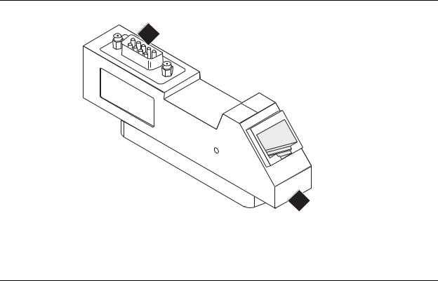
Media server cable adapter
The media server cable adapter is mounted on the rear of the TN8400AP Media Server circuit pack. The media server cable adapter provides the connection between the backplane pins and RJ-45 connectors for:
●four backplane Ethernet ports
●one backplane USB port
See Figure 1: Media server cable adapter on page 15.
Figure 1: Media server cable adapter
|
1 |
|
|
|
2 |
USB |
-A |
|
|
ETH |
3 |
|
|
4
ETH-B |
-C |
|
|
ETH |
-D |
|
|
ETH |
5
|
|
|
addp84bk LAO 112905 |
Figure notes: |
|
|
|
1. |
USB modem connector |
4. |
Not used |
2. |
Connection to TN8412AP circuit pack |
5. |
Not used |
3. |
Connection to LAN |
|
|
|
|
|
|
Installing and Configuring the Avaya S8400 Media Server |
February 2006 15 |

Chapter 1: Introduction
Table 3: Media server cable adapter port labeling on page 16 describes the connections for the media server cable adapter.
Table 3: Media server cable adapter port labeling
|
Location (counting from |
Port Name |
Adapter |
Function |
|
|
the top of the adapter) |
|
Label |
|
|
|
|
|
|
|
|
|
USB |
Backplane USB |
USB |
Provides power to the USB modem, |
|
|
|
modem port |
|
|
can hard reset the USB modem, |
|
|
|
|
|
provides a USB modem interface to |
|
|
|
|
|
support Services remote alarming |
|
|
|
|
|
and access. |
|
|
|
|
|
|
|
Top Ethernet |
Ethernet |
ETH-A |
10/100Base T Mbps Ethernet |
|
|
|
connectivity with |
|
|
Interface for the control links - uses |
|
|
the TN8412AP |
|
|
crossover cable to connect directly |
|
|
circuit pack |
|
|
to the SIPI. |
|
Second Ethernet |
Ethernet |
ETH-B |
10/100Base T Mbps Ethernet |
|
|
|
connectivity with |
|
|
Interface to the customer LAN. |
|
|
the LAN |
|
|
Messaging over IP. |
|
|
|
|
|
|
|
|
|
|
|
Connections to adjuncts and IP |
|
|
|
|
|
endpoints. |
|
|
|
|
|
Remote administration over IP. |
|
|
|
|
|
|
|
Third Ethernet |
Future |
ETH-C |
Not used |
|
|
|
|
|
|
|
|
Bottom Ethernet |
Future |
ETH-D |
Not used |
|
|
|
|
|
|
|
|
|
|
|
|
|
|
|
|
|
|
|
Ethernet connectivity with the TN8412AP circuit pack
The S8400 Media Server supports connectivity with the TN8412AP (SIPI) circuit pack through a 10/100 BaseT Ethernet twisted pair on the IPSI-2 cable adapter. This interface is for control only - no bearer traffic is carried over this connection. This Ethernet is connected to the Communication Manager Processor complex. The IPSI-2 cable adapter is mounted on the rear of the TN8412AP SIPI circuit pack.
The physical connection between the TN8412AP and the TN8400 circuit packs is made by either:
1.Using a 10/100 Base T Ethernet crossover cable that directly interconnects the appropriate backplane pins of the two circuit packs. This cable plugs into the TN8400AP cable adapter RJ45 ETH-A port and the TN8412AP IPSI-2 adapter RJ45 control port.
2.Connection to the customer LAN.
16 Installing and Configuring the Avaya S8400 Media Server |
February 2006 |
About media server port connections
IPSI-2 cable adapter on page 17 shows the IPSI-2 cable adapter for the S8412AP SIPI circuit pack.
Figure 1: IPSI-2 cable adapter
1
ETHERNET 10/100bT
2
addpipsi LAO 112905
Figure notes:
1. D9 connector |
2. RJ45 for connection to the TN8400 or LAN |
Figure 2: Cable adapters on TN8412AP and TN8400AP circuit packs in a G650 on page 18 shows the location of the two backplane adapters on a G650.
Installing and Configuring the Avaya S8400 Media Server |
February 2006 17 |

Chapter 1: Introduction
Figure 2: Cable adapters on TN8412AP and TN8400AP circuit packs in a G650
1
USB  ETH-A
ETH-A 
ETH-B  ETH-C
ETH-C  ETH-D
ETH-D 
2
|
|
|
BU |
G |
|
232 |
DE |
|
|
RS |
|
|
|
|
|
|
|
|
ETHERNET
10/100bT
h2dp650b LAO 121605
Figure notes:
1.Media server cable adapter on the TN8400AP Media Server circuit pack
2.IPSI-2 cable adapter on the TN8412AP SIPI circuit pack
18 Installing and Configuring the Avaya S8400 Media Server |
February 2006 |

About media server port connections
Services access port
The S8400 Media Server has one Services laptop access port that is off the Maintenance Processor. Use this port to access the MPC and the media server on the S8400AP circuit pack.
Table 4: Services access on the MPC on page 19 lists the Services access protocols. The MPC receives Service requests on only two TCP ports: 10022 (Secure Shell access) and 10443 (Secure Web access).
Table 4: Services access on the MPC
Access Method |
Service |
IP Address |
TCP Port |
Service Granted |
|
Requested |
|
|
|
|
|
|
|
|
Services laptop |
SSH |
192.11.13.6 |
10022 |
Secure Shell access to MPC |
|
|
|
|
|
Services laptop |
HTTPS |
192.11.13.6 |
10443 |
Secure Web access to MPC |
|
|
|
|
|
Services laptop |
SSH |
192.11.13.6 |
22 |
Secure Shell access to media |
|
|
|
|
server |
|
|
|
|
|
Services laptop |
HTTPS |
192.11.13.6 |
443 |
Secure Web access to media |
|
|
|
|
server |
Services laptop |
Telnet |
192.11.13.6 |
23 |
Access to media server |
|
|
|
|
|
Services laptop |
Telnet |
192.11.13.6 |
5023 |
Access to SAT on media |
|
|
|
|
server |
Modem dial-in |
ppp>SSH |
Modem IP |
10022 |
Secure Shell access to MPC |
|
|
address |
|
|
|
|
|
|
|
Modem dial-in |
ppp>HTTPS |
Modem IP |
10443 |
Web https access to MPC |
|
|
address |
|
|
Modem dial-in |
ppp>SSH |
Modem IP |
22 |
Secure Shell access to media |
|
|
address |
|
server |
|
|
|
|
|
Modem dial-in |
ppp>HTTPS |
Modem IP |
443 |
Secure Web access to media |
|
|
address |
|
server |
Modem dial-in |
ppp>Telnet |
Modem IP |
23 |
Access to media server |
|
|
address |
|
|
|
|
|
|
|
Modem dial-in |
ppp>Telnet |
Modem IP |
5023 |
Access to SAT on media |
|
|
address |
|
server |
Modem dial-in |
ppp>SSH |
Modem IP |
5022 |
Secure access to SAT on |
|
|
address |
|
media server |
|
|
|
|
|
|
|
|
|
|
Installing and Configuring the Avaya S8400 Media Server |
February 2006 19 |

Chapter 1: Introduction
About Modem connections
Note:
USB modems cannot connect to rotary lines. A Touch Tone line is required.
The TN8400AP Media Server circuit pack supports a USB modem. The modem communicates directly to the maintenance processor or tunnels through to the Communication Manager processor application. The modem provides Avaya Services with remote alarming and dial-in and dial-out access.
Connect the USB modem to port labeled USB on the media server cable adapter. The adapter is mounted on the rear of the TN8400AP Media Server circuit pack.
Modem options are set when you configure the media server. No options are set on the modems themselves.
About Media Gateways
In a new installation, the S8400 Media Server is installed only in the Avaya G650 Media Gateway.
In a migration the media server is installed only in the following Avaya Media Gateways:
●G600
●CMC1
In addition, the media servers work with Avaya G150, G250, G350, and G700 Media Gateways. These gateways register with the S8400 either through the S8400 Processor Ethernet interface or through a TN799DP C-LAN circuit pack.
20 Installing and Configuring the Avaya S8400 Media Server |
February 2006 |
About Processor Ethernet
About Processor Ethernet
Like a C-LAN board, Processor Ethernet provides connectivity to IP endpoints, gateways, and adjuncts. The PE interface is a logical connection in the Communication Manager software that uses a port on the NIC in the server. There is no additional hardware needed to implement PE.
Starting with release 3.1 of Communication Manager, the PE interface is enabled on theS8400 Media Server allowing enhanced flexibility for connectivity to gateways, endpoints, and adjuncts.
Table 5 lists the possible uses of the PE interface for an S8400.
Table 5: Use of the PE interface on the S8400 Media Server
Possible functions of |
Status of the function |
Administration needed |
the PE interface |
on the server |
|
|
|
|
Registration |
The PE interface is |
No. The use of the PE interface for |
|
always enabled for |
registration is enabled automatically by |
|
registration. |
the Communication Manager software. |
|
|
|
H.248 gateway |
H.248 gateway |
The H.248 gateway enabled field on |
registration |
registration is enabled by |
the ip-interface procr form defaults to a |
|
default on the S8400 |
yes on an S8400 Media Server. You |
|
Media Server |
can disable the H.248 registration by |
|
|
changing the H.248 gateway enabled |
|
|
field on the ip-interfaces procr form to a |
|
|
no. |
|
|
|
H.323 endpoint |
H.323 registration is |
The H.323 endpoint enabled field on |
registration |
enabled by default on the |
the ip-interface procr form defaults to a |
|
S8400 Media Server. |
yes on an S8400 Media Server. You |
|
|
can disable H.323 endpoint registration |
|
|
by changing the H.323 enabled field on |
|
|
the ip-interfaces procr form to a no. |
|
|
|
Adjunct connectivity |
Connectivity of adjunct is |
Yes. Adjuncts must be administered on |
|
enabled by default on the |
the S8400 Media Server. |
|
S8400 Media Server. |
|
|
|
|
|
|
|
Installing and Configuring the Avaya S8400 Media Server |
February 2006 21 |

Chapter 1: Introduction
About SSH
Secure Shell (SSH) is both a computer program and an associated network protocol designed for logging into and executing commands on a networked computer. SSH provides secure encrypted communications between two untrusted hosts over an insecure network. Avaya recommends using SSH instead of Telnet for most interactive connections to the Avaya media servers and other devices on a customer’s network.
To use SSH, a third-party SSH client must be installed on your computer. PuTTY is one such client available for download from http://www.putty.nl/download.html.
Devices that can be accessed with SSH include:
●Media servers on Release 3.1 of Communication Manager: S8300, S8400, S8500, S8700-series
May include port number reference 5022 for direct SAT access.
●Server Availability Management Processor (SAMP) (used with S8500 Media Server) May include port number reference 10022 for direct access
●Maintenance Processor Complex (MPC) (used with S8400 Media Server) May include port number reference 10022 for direct access
●TN2312BP IPSI running firmware version 20 or higher
●TN8412AP SIPI
●TN2602 IP Media Resource 360 running firmware version 212 or higher
●Expanded Meet-Me Conferencing (EMMC) and the S6100 Media Server
●SIP server
●G250 and G350 media gateways
●C360 Ethernet switches
!Important:
G700 does not allow the use of SSH. From within a media server's Linux command line, you can use SSH to access the G250 and G350, but you must use telnet to access the G700. In this case, the server is the SSH client, not PuTTY.
22 Installing and Configuring the Avaya S8400 Media Server |
February 2006 |

High level overview of installation process
High level overview of installation process
The installation process is completed in stages. Some stages can be completed in parallel, and others require that certain tasks be accomplished before the stages can be completed. The order that the particular stages are completed depends on local practice and the personnel available. The high level stages are listed below.
Installing and cabling the media gateways
Install and connect the media gateways before installing and configuring the S8400 Media Server. The media gateways must be installed and powered up to effectively complete many of the other stages. A powered-up media gateway is required for software installation and configuration on the S8400 Media Server and programming of the SIPI circuit pack. See the Quick Start documentation for your system for instructions.
Installing Avaya Communication Manager
A new S8400 Media Server comes with a blank hard drive and a blank solid state device (SSD). Use the bootable software distribution CD-ROM to install the Linux operating system and Avaya Communication Manager.
Configuring the MPC
The Maintenance Processor Complex (MPC) monitors various components and environmentals on the media server. The board comes installed from the factory with Avaya defaults but must be configured to fit your specific installation. The MPC is administered automatically through the Avaya Installation Wizard.
Configuring the media server
Use the Avaya Installation Wizard to configure the media server. You must have the filled-out Electronic Preinstallation Worksheet (EPW) that provides the customer’s network information needed for configuring the network components. As part of the Wizard, you install the license and Avaya authentication files. This stage is done after installing the software.
Installing and Configuring the Avaya S8400 Media Server |
February 2006 23 |

Chapter 1: Introduction
Translating the SIPI
When configuring the media server (or both media servers in a duplicated system), the Avaya Installation Wizard installs the license file.The SIPI circuit packs must be translated within 30 minutes after the license file is installed.
Completing the installation administration
Finish the media server installation by clearing alarms, enabling alarm reporting, backing up the server files, and registering the configuration.
Testing the finished installation
This stage verifies the complete configuration operation and is the last task.
24 Installing and Configuring the Avaya S8400 Media Server |
February 2006 |

Configuration of the SNMP modules in the UPS
Chapter 2: SNMP Configuration
After the control network equipment is installed and connected, configure the SNMP modules to send alarms (traps) to the media servers.
Configure:
●the SNMP modules in each UPS (if supplied by Avaya)
●the SNMP Subagent in the Avaya Ethernet switch (if supplied by Avaya)
First configure the SNMP agents. Then install Avaya Communication Manager on the media server, configure the media server, and verify its operation. In a duplicated system, install Avaya Communication Manger on the first media server and verify its operation before you repeat the process on the second media server.
This section covers Configuration of the SNMP modules in the UPS on page 25
Configuration of the SNMP modules in the UPS
Note:
These instruction apply only if using a new, Avaya-supplied uninterruptible power supply (UPS) with a simple network management protocol (SNMP) module. Do not use these procedures to set traps on a non-Avaya-supplied UPS.
The SNMP module in the UPS must be administered so it reports alarms to the media server when the hardware experiences problems. The module reports the loss of commercial power and the depletion of battery resources.
For the SNMP module to properly report alarms, a unique IP address for the UPS must be configured on both the SNMP module and the media server. This IP address can be a customer-provided one or the Avaya-provided default one. At a minimum, the following items must be configured:
●IP address
●Subnet mask
●Gateway IP address
●Trap receiver IP address
●Community string (get, set, trap)
Installing and Configuring the Avaya S8400 Media Server |
February 2006 25 |

Chapter 2: SNMP Configuration
Because the SNMP module is manufactured by a third party, we do not know which brand, model, or firmware load the factory is shipping. Therefore, we cannot provide specific instructions in this document on how to connect to and configure the SNMP module. See the documentation that comes with the SNMP module. The default password and the configuration commands are in the local configuration section of the User Guide.
Default UPS IP addresses
Administer the SNMP module in the UPS following the steps in Administering the SNMP module on page 27. The default IP addresses for the UPS are shown in the table.
IP address for UPS |
198.152.254.239 |
|
|
Subnet mask for UPS |
255.255.255.0 |
|
|
Gateway address for UPS |
198.152.254.201 |
|
|
IP address for |
customer provided |
Trap receiver (media server) |
|
|
|
Preparing to configure the SNMP module
Before you configure the SNMP module, make sure you have the hardware connected correctly and all the information you need.
●Ensure you are plugged into the correct administration port on the SNMP module.
●Ensure the UPS is plugged into a nonswitched electrical outlet.
Note:
Avaya Terminal Emulation and HyperTerminal are supported terminal emulation applications.
●When using your terminal emulation application, ensure that your laptop communication protocol has the following port settings:
-9600 baud
-No parity
-8 data bits
-1 stop bit
-No flow control
26 Installing and Configuring the Avaya S8400 Media Server |
February 2006 |

Configuration of the SNMP modules in the UPS
●If a Network Management System (NMS) is going to monitor the UPS, coordinate the assignment of community names with the network administrator.
If an NMS is not going to monitor the UPS, set the community names to unique string values.
!SECURITY ALERT:
The Get and Set, community name strings are initially configured with default values of Public and Private, respectively. These community name strings function as passwords for their respective SNMP operation. It is always a good idea to change these community name strings to something other than the default values. If the defaults are left in place, they could result in a serious security issue.
See Setting selected traps (alarming) on page 28 for information on which traps to set.
●If the control network is nondedicated (going over the customer's network), make sure that the 162/udp port for input to server is enabled (the default is disabled). Otherwise, the media server cannot receive the traps from the UPS(s). See Enabling firewall settings on page 40.
Administering the SNMP module
Note:
Use the default addresses in the tables.
1.Connect the services laptop computer (RS-232 serial port) to the DB-9 connector on the back of the SNMP module for UPS1 using the DB-9 to DB-9 serial cable supplied with the SNMP module.
2.Open a VT-100 terminal emulation session on the services laptop.
3.Set the IP address for the UPS.
4.Set the subnet mask for the UPS.
5.Set the gateway address for the UPS.
6.Set the IP address of the trap receiver (media server) for the UPS.
7.Set the SNMP community name string for Get, Set, and Trap. See Setting selected traps (alarming) on page 28 for information on which traps to set.
8.When completed, disconnect the services laptop computer from the UPS.
9.Connect one end of a CAT5 straight-through cable to the RJ45 connector on the UPS SNMP module and the other end to the next available port on the Ethernet switch for Control Network A (CNA).
For a connectivity guide, see the Quick Start for Hardware Installation: Avaya S8400 Media Server in an Avaya G650 Media Gateway (03-300705).
Installing and Configuring the Avaya S8400 Media Server |
February 2006 27 |
Loading...