


 Loading...
Nortel Business Communications Manager 450
Maintenance
Release: 5.0
Document Revision: 02.03
NN40170-503
Document status: Standard
Document issue: 02.04
Document date: August 2009
Product release: BCM 5.0
Job function: Maintenance
Type: NTP
Language type: English
Copyright © 2009 Nortel Networks
All Rights Reserved.
NORTEL, the globemark design, and the NORTEL corporate logo are trademarks of Nortel Networks.
Maxell is a trademark of Hitachi Maxell, Ltd.
All other trademarks are the property of their respective owners.

Contents
New in this release |
|
|
5 |
||
Features 5 |
|
|
|
|
|
|
|
|
|
|
|
Introduction |
|
|
|
|
7 |
|
|
|
|
||
System maintenance |
|
|
9 |
||
|
|
|
|||
BCM450 equipment replacement |
|
11 |
|||
|
|
||||
BCM450 internal component replacement |
13 |
||||
Replacing a media bay module 15 |
|
|
|
||
Prerequisites 15 |
|
|
|
|
|
Procedure steps |
15 |
|
|
|
|
Removing the power supply 16 |
|
|
|
||
Connecting the new power supply 17 |
|
|
|||
Removing the hard disk |
17 |
|
|
|
|
Installing the hard disk |
18 |
|
|
|
|
Installing the CEC |
19 |
|
|
|
|
Replacing memory |
21 |
|
|
|
|
Prerequisites 21 |
|
|
|
|
|
Removing the cooling fan 22 |
|
|
|
||
Installing the fan 22 |
|
|
|
|
|
Replacing the clock/calendar battery |
23 |
|
|
||
Prerequisites 24 |
|
|
|
|
|
Procedure steps |
24 |
|
|
|
|
|
|
||||
Redundant power supply installation |
25 |
||||
Prerequisites for redundant power supply installation |
25 |
||||
Redundant power supply installation navigation 26 |
|
||||
Removing the PSU status connector jumper |
26 |
|
|||
Procedure steps |
27 |
|
|
|
|
Installing the redundant power supply cage |
28 |
|
|||
Procedure steps |
28 |
|
|
|
|
Installing the secondary cooling fan |
31 |
|
|
||
Procedure steps |
32 |
|
|
|
|
Installing the power supply modules |
33 |
|
|
||
Business Communications Manager 450
Maintenance
NN40170-503 02.04 Standard
August 2009
Copyright © 2009 Nortel Networks

4 Contents
Procedure steps 34
Common procedures |
|
35 |
Disconnecting the cables from the main unit |
35 |
|
Disconnecting the cables from the expansion cabinet 36 |
||
Shutting down the system for maintenance |
36 |
|
Returning the system to operation |
38 |
|
Removing the BCM450 base function tray 39 |
||
Prerequisites 39 |
|
|
Procedure steps 39 |
|
|
Reinstalling the BCM450 base function tray |
40 |
|
Prerequisites 40 |
|
|
Procedure steps 40 |
|
|
Removing the BCM450 main unit top cover |
40 |
|
Prerequisites 41 |
|
|
Procedure steps 41 |
|
|
Installing the main unit top cover |
42 |
|
Prerequisites 42 |
|
|
Procedure steps 42 |
|
|
BCM modules management |
|
45 |
Disabling or enabling a bus or module 46 |
|
|
Disabling or enabling a port channel setting 47 |
|
|
Configuring a Station Module type BCM450 MBM |
47 |
|
Deconfiguring a Station Module type BCM450 MBM |
48 |
|
48 |
|
|
Configuring a Trunk Module or Combination MBM |
49 |
|
Deconfiguring a Trunk Module or Combination MBM |
49 |
|
49 |
|
|
|
|
|
System LEDs reference |
|
51 |
System status monitor LEDs 51 |
|
|
Hard disk drive LEDs on BCM450 52 |
|
|
Business Communications Manager 450
Maintenance
NN40170-503 02.04 Standard
August 2009
Copyright © 2009 Nortel Networks

New in this release
The following sections detail what’s new in Nortel Business Communications Manager 450—Maintenance in Release 5.0:
•“Features (page 5)”
Features
•BCM450 5.0 supports RAID for disk mirroring. This allows you to maintain a redundant image of your hard drive to maintain service in the event of a hard disk failure. For more information, see Removing the hard disk (page 17) and Installing the hard disk (page 18).
Business Communications Manager 450
Maintenance
NN40170-503 02.04 Standard
August 2009
Copyright © 2009 Nortel Networks

6 New in this release
Business Communications Manager 450
Maintenance
NN40170-503 02.04 Standard
August 2009
Copyright © 2009 Nortel Networks

Introduction
This document describes how to maintain Business Communications Manager BCM systems.
Navigation
•System maintenance (page 9)
•BCM450 equipment replacement (page 11)
•BCM450 internal component replacement (page 13)
•Redundant power supply installation (page 25)
•BCM modules management (page 45)
•Common procedures (page 35)
•System LEDs reference (page 51)
Business Communications Manager 450
Maintenance
NN40170-503 02.04 Standard
August 2009
Copyright © 2009 Nortel Networks

8 Introduction
Business Communications Manager 450
Maintenance
NN40170-503 02.04 Standard
August 2009
Copyright © 2009 Nortel Networks

System maintenance
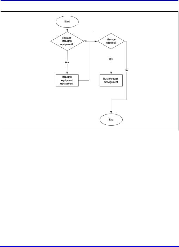
To maintain your Business Communications Manager (BCM) system, you can replace damaged equipment, manage installed modules, and use BCM utilities to monitor performance and track statistics.
Prerequisites to system maintenance
•Ensure your BCM system is properly installed. For more information about installing a BCM system, see Nortel Business Communications Manager 450 5.0 Installation — System (NN40170-303).
System maintenance tasks
This work flow shows you the sequence of tasks you perform to maintain your BCM system. To link to any tasks, click on System maintenance navigation (page 10).
Business Communications Manager 450
Maintenance
NN40170-503 02.04 Standard
August 2009
Copyright © 2009 Nortel Networks
10 System maintenance
Figure 1 System maintenance tasks
System maintenance navigation
•BCM450 equipment replacement (page 11)
•BCM modules management (page 45)
Business Communications Manager 450
Maintenance
NN40170-503 02.04 Standard
August 2009
Copyright © 2009 Nortel Networks
BCM450 equipment replacement
Replace BCM450 equipment and components when they are damaged.
WARNING
Risk of leakage currents
You must disconnect the telephony and data networking cables from the system before disconnecting the power cord from a grounded outlet.
Equipment replacement tasks
This work flow shows you the sequence of tasks you perform to replace equipment for your BCM450 system. To link to any tasks, click on Equipment replacement navigation (page 12).
Business Communications Manager 450
Maintenance
NN40170-503 02.04 Standard
August 2009
Copyright © 2009 Nortel Networks
12 BCM450 equipment replacement
Figure 2 Equipment replacement tasks
Equipment replacement navigation
•BCM450 internal component replacement (page 13)
Business Communications Manager 450
Maintenance
NN40170-503 02.04 Standard
August 2009
Copyright © 2009 Nortel Networks
BCM450 internal component replacement
You can replace components in the BCM450 main unit if they are defective or damaged.
Prerequisites to BCM450 internal component replacement
•Ensure the BCM450 system is shut down. For more information, see Shutting down the system for maintenance (page 36).
•Disconnect the main unit from the power outlet.
•Remove the BCM450 main unit from the rack, wall, or desktop and set it on a flat, clean, static-free surface.
•Ensure you have the following tools:
—Phillips screwdriver #2, with a 3.5-inch blade
—3/16-inch slot screwdriver
—Antistatic wrist grounding strap
CAUTION
Risk of damage to equipment
You must wear an antistatic grounding strap at all times when handling electronic components. Failure to do so can result in damage to the equipment.
CAUTION
Risk of information loss and damage to equipment
Do not use an electric or magnetized screwdriver near the hard disk. You can lose the information stored on the disk. Shock can damage the hard disk. Do not drop or hit the hard disk.
Business Communications Manager 450
Maintenance
NN40170-503 02.04 Standard
August 2009
Copyright © 2009 Nortel Networks

14 BCM450 internal component replacement
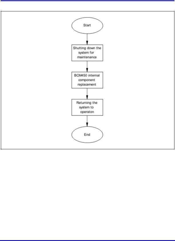
BCM450 internal component replacement procedures
This task flow shows you the sequence of procedures you perform to replace an internal component in a BCM450 main unit. To link to any procedure, click on BCM450 internal component replacement navigation (page 14).
Figure 3 BCM450 internal component replacement procedures
BCM450 internal component replacement navigation
•Replacing a media bay module (page 15)
•Removing the power supply (page 16)
•Connecting the new power supply (page 17)
•Removing the hard disk (page 17)
•Installing the hard disk (page 18)
•Installing the CEC (page 19)
•Replacing memory (page 21)
•Removing the cooling fan (page 22)
•Installing the fan (page 22)
•Replacing the clock/calendar battery (page 23)
Business Communications Manager 450
Maintenance
NN40170-503 02.04 Standard
August 2009
Copyright © 2009 Nortel Networks

BCM450 internal component replacement 15
Replacing a media bay module
This section describes how to replace a media bay module (MBM) installed in your BCM450 main unit or expansion cabinet if it is defective or damaged.
This section describes replacing an MBM with the same type of MBM. If you want to replace an MBM with a different type of MBM, you must treat it as a new installation. Ensure the new MBM does not overrun any lines already assigned to other MBMs.
Prerequisites
•Turn off the BCM450 system. For more information, see “Shutting down the system for maintenance (page 36)”.
•Ensure the BCM450 main unit is disconnected from the AC power source.
Procedure steps
Step Action
1Remove any cabling from the MBM faceplate.
2Grasp the right edge of the MBM ejector lever with your thumb, index and middle fingers.
3Pull outward to partially eject the MBM. Pull further on the lever to eject the MBM from the bay.
4Grasp the top and bottom edges of the MBM, and remove it from the BCM unit. Place the MBM in a clean, safe, and static-free area.
5Set the DIP switches on the new MBM to match the settings of the old MBM.
6Install the new MBM in the main unit or expansion cabinet. For more information about installing an MBM, see Nortel Business Communications Manager 450 Installation — System.
7Return the BCM450 system to normal operation.
--End--
Business Communications Manager 450
Maintenance
NN40170-503 02.04 Standard
August 2009
Copyright © 2009 Nortel Networks
16 BCM450 internal component replacement
Removing the power supply
Remove the defective power supply from your BCM450 main unit or BCM450 expansion cabinet before installing the new power supply.
WARNING
Risk of leakage currents
You must disconnect the telephony and data networking cables from the system before disconnecting the power cord from a grounded outlet.
CAUTION
Risk of equipment damage
Protect the hardware components against damage from electrostatic discharge. Always wear a grounded wrist strap before you handle components. Always place the components in a static-free container.
Procedure steps
Step Action
1Shut down the BCM450 system. For more information, see Shutting down the system for maintenance (page 36).
2Disconnect all cables from the front of the base function tray.
3Disconnect the main unit and the expansion cabinet (if applicable) from the AC power connection.
4Attach one end of the grounding strap to your wrist and the other end to a grounded metal surface.
5Loosen the screws securing the power supply module (located at the back of the unit, on the right).
6Pull handle located on the power supply module outward to remove the power supply module from the unit.
--End--
Business Communications Manager 450
Maintenance
NN40170-503 02.04 Standard
August 2009
Copyright © 2009 Nortel Networks

BCM450 internal component replacement 17
Connecting the new power supply
After you remove the defective power supply, connect the new power supply to your BCM450 main unit or BCM450 expansion cabinets.
Prerequisites
•Ensure that the new power supply is an auto adjust power supply.
Procedure steps
Step Action
1Firmly slide the power supply module directly into the power supply bay.
2Tighten the screws to secure the power supply module.
--End--
Removing the hard disk
Remove the damaged hard disk before installing the new hard disk.
CAUTION
Risk of damage to equipment
Do not use an electric or magnetized screwdriver near the hard disk. You can lose the information stored on the disk. Shock can damage the hard disk. Do not drop or hit the hard disk.
Procedure steps
Step Action
1In Business Element Manager, go to Administration >System Metrics>Disk Mirroring. Determine whether it is HDD-1 in the first (left) hard disk slot or HDD-2 in the second (right) slot that has failed.
The Status section will list one of the drives as Failed and not Passed. If the system has been rebooted since the failure has occurred, depending on the type of hard disk failure, a second drive may not be listed in this section. In that case, the drive that is installed but does not have a lit HDD LED and is not listed in the Status section will be the failed disk to be replaced.
2Turn off the BCM450 system and disconnect it from the AC power source. For more information, see Shutting down the system for maintenance (page 36).
Business Communications Manager 450
Maintenance
NN40170-503 02.04 Standard
August 2009
Copyright © 2009 Nortel Networks
Loading...