


DMC DECT Fundamentals
Table of contents
 Loading...
DMC DECT Fundamentals
A
vaya Communications Server 1000
NN43120-114, 02.07
Release 7.5
August 2012

©
Avaya Inc.
2012
All Rights Reserved.
Notice
While reasonable efforts have been made to ensure that the
information in this document is complete and accurate at the time of
printing, Avaya assumes no liability for any errors. Avaya reserves the
right to make changes and corrections to the information in this
document without the obligation to notify any person or organization of
such changes.
Documentation disclaimer
“Documentation” means information published by Avaya in varying
mediums which may include product information, operating instructions
and performance specifications that Avaya generally makes available
to users of its products. Documentation does not include marketing
materials. Avaya shall not be responsible for any modifications,
additions, or deletions to the original published version of
documentation unless such modifications, additions, or deletions were
performed by Avaya. End User agrees to indemnify and hold harmless
Avaya, Avaya's agents, servants and employees against all claims,
lawsuits, demands and judgments arising out of, or in connection with,
subsequent modifications, additions or deletions to this documentation,
to the extent made by End User.
Link disclaimer
Avaya is not responsible for the contents or reliability of any linked Web
sites referenced within this site or documentation provided by Avaya.
Avaya is not responsible for the accuracy of any information, statement
or content provided on these sites and does not necessarily endorse
the products, services, or information described or offered within them.
Avaya does not guarantee that these links will work all the time and has
no control over the availability of the linked pages.
Warranty
Avaya provides a limited warranty on its Hardware and Software
(“Product(s)”). Refer to your sales agreement to establish the terms of
the limited warranty. In addition, Avaya’s standard warranty language,
as well as information regarding support for this Product while under
warranty is available to Avaya customers and other parties through the
Avaya Support Web site:
you acquired the Product(s) from an authorized
of the United States and Canada, the warranty is provided to you by
said Avaya reseller and not by Avaya.
Licenses
THE SOFTWARE LICENSE TERMS AVAILABLE ON THE AVAYA
WEBSITE,
APPLICABLE
INSTALLS AVAYA SOFTWARE, PURCHASED FROM AVAYA INC.,
ANY AVAYA AFFILIATE, OR AN AUTHORIZED AVAYA RESELLER
(AS APPLICABLE) UNDER A COMMERCIAL AGREEMENT WITH
AVAYA OR AN AUTHORIZED AVAYA RESELLER. UNLESS
OTHERWISE AGREED TO BY AVAYA IN WRITING, AVAYA DOES
NOT EXTEND THIS LICENSE IF THE SOFTWARE WAS OBTAINED
FROM ANYONE OTHER THAN A V A Y A, AN A V A Y A AFFILIA TE OR AN
AVAYA AUTHORIZED RESELLER; AVAYA RESERVES THE RIGHT
TO TAKE LEGAL ACTION AGAINST YOU AND ANYONE ELSE
USING OR SELLING THE SOFTWARE WITHOUT A LICENSE. BY
INSTALLING, DOWNLOADING OR USING THE SOFTWARE, OR
AUTHORIZING OTHERS TO DO SO, YOU, ON BEHALF OF
YOURSELF AND THE ENTITY FOR WHOM YOU ARE INSTALLING,
DOWNLOADING OR USING THE SOFTWARE (HEREINAFTER
REFERRED TO INTERCHANGEABL Y AS “YOU” AND “END USER”),
AGREE TO THESE TERMS AND CONDITIONS AND CREATE A
BINDING CONTRACT BETWEEN YOU AND AVAYA INC. OR THE
APPLICABLE AVAYA AFFILIATE (“AVAYA”).
HTTP://SUPPORT.AVAYA.COM/LICENSEINFO/ ARE
TO ANYONE WHO DOWNLOADS, USES AND/OR
http://support.avaya.com. Please note that if
Avaya reseller outside
Copyright
Except where expressly stated otherwise, no use should be made of
materials on this site, the Documentation, Software, or Hardware
provided by
Product provided by Avaya including the selection, arrangement and
design of the content is owned either by Avaya or its licensors and is
protected by copyright and other intellectual property laws including the
sui generis rights relating to the protection of databases. You may not
modify, copy, reproduce, republish, upload, post, transmit or distribute
in any way any content, in whole or in part, including any code and
software unless expressly authorized by Avaya. Unauthorized
reproduction, transmission, dissemination, storage, and or use without
the express written consent of Avaya can be a criminal, as well as a
civil offense under the applicable law.
Third-party components
Certain software programs or portions thereof included in the Product
may contain software distributed under third party agreements (“Third
Party Components”), which may contain terms that expand or limit
rights to use certain portions of the Product (“Third Party Terms”).
Information regarding distributed Linux OS source code (for those
Products that have distributed the Linux OS source code), and
identifying the copyright holders of the Third Party Components and the
Third Party Terms that apply to them is available on the A vaya Support
Web site:
Preventing T
“T oll fraud” is the unauthorized use of your telecommunications system
by an unauthorized party (for example, a person who is not a corporate
employee, agent, subcontractor, or is not working on your company's
behalf). Be aware that there can be a risk of Toll Fraud associated with
your system and that, if Toll Fraud occurs, it can result in substantial
additional charges for your telecommunications services.
Avaya Toll Fraud Intervention
If you suspect that you are being victimized by T oll Fraud and you need
technical assistance or support, call Technical Service Center Toll
Fraud Intervention Hotline at +1-800-643-2353 for the United States
and Canada. For additional support telephone numbers, see the Avaya
Support Web site:
vulnerabilities with
sending mail to: securityalerts@avaya.com.
Trademarks
The trademarks, logos and service marks (“Marks”) displayed in this
site, the Documentation and Product(s) provided by Avaya are the
registered or unregistered Marks of Avaya, its affiliates, or other third
parties. Users are not permitted to use such Marks without prior written
consent from Avaya or such third party which may own the Mark.
Nothing contained in this site, the Documentation and Product(s)
should be construed as granting, by implication, estoppel, or otherwise,
any license or right in and to the Marks without the express written
permission of Avaya or the applicable third party.
Avaya is a registered trademark of Avaya Inc.
All non-Avaya trademarks are the property of their respective owners,
and “Linux” is a registered trademark of Linus Torvalds.
Downloading Documentation
For the most current versions of Documentation, see the Avaya
Support Web site:
Contact
See the Avaya Support W eb site:
notices and articles, or to report a problem with your Avaya product.
For a list of support telephone numbers and contact addresses, go to
the Avaya Support Web site:
bottom of the page, and select Contact
Avaya. All content on this site, the documentation and the
http://support.avaya.com/Copyright.
oll Fraud
http://support.avaya.com. Suspected security
Avaya products should be reported to Avaya by
http://support.avaya.com.
Avaya Support
http://support.avaya.com
http://support.avaya.com, scroll to the
Avaya Support.
for product
2 DMC DECT Fundamentals August 2012
Comments? infodev@avaya.com

Contents
Chapter 1: New in this release...........................................................................................
Revision History........................................................................................................................................
Chapter 2: Product description.........................................................................................
Contents....................................................................................................................................................
Overview...................................................................................................................................................
Clock requirements..........................................................................................................................
CS 1000E.........................................................................................................................................
Synchronization port.........................................................................................................................
Mobility card (DMC8)................................................................................................................................
DMC8 options...................................................................................................................................
DMC8 - Expander (DMC8-E)...........................................................................................................
Faceplate features............................................................................................................................
DMC Faceplate cables.....................................................................................................................
IPE Shelves Faceplate Cabling........................................................................................................
Inter-shelf faceplate connections......................................................................................................
MG1000E Chassis faceplate cabling...............................................................................................
Basestations..............................................................................................................................................
Basestation housing.........................................................................................................................
Basestation cell................................................................................................................................
DECT handset subscription and de-subscription......................................................................................
DMC DECT Manager................................................................................................................................
DECT Application features...............................................................................................................
Common Services............................................................................................................................
Remote Access Service (RAS)........................................................................................................
Multi-site Mobility Networking subscriptions..............................................................................................
Multi-site Mobility Networking....................................................................................................................
Operating parameters......................................................................................................................
Call forward from a MADN handset..................................................................................................
Card audit.........................................................................................................................................
Network Message Service................................................................................................................
Feature packaging............................................................................................................................
Messaging and Alarms..............................................................................................................................
Chapter 3: Engineering guidelines....................................................................................
Contents....................................................................................................................................................
System capabilities and limits...................................................................................................................
System concentration traffic......................................................................................................................
Blocking............................................................................................................................................
Traffic definitions..............................................................................................................................
Traffic assumptions used for table calculations................................................................................
System hardware parameters..........................................................................................................
System software parameters............................................................................................................
DMC8 engineering guidelines...................................................................................................................
Netprice Order Tool..........................................................................................................................
DECT on Large Systems..................................................................................................................
11
11
13
13
13
14
14
17
17
18
19
19
21
23
23
25
25
27
27
28
29
29
30
30
32
33
34
34
34
34
34
35
37
37
37
37
37
38
38
39
41
41
43
43
DMC DECT Fundamentals August 2012 3

DECT on Cabinet system.................................................................................................................
DECT on Chassis system................................................................................................................
DECT on CS 1000E.........................................................................................................................
Rules with new basestations............................................................................................................
Basestation combinations for handsets on a DMC8.................................................................................
Low traffic for a 0.1 Erlang capacity.................................................................................................
Medium traffic for a 0.15 Erlang capacity.........................................................................................
High traffic for a 0.2 Erlang capacity.................................................................................................
Superloop and IPE shelf calculations...............................................................................................
Chapter 4: Site planning.....................................................................................................
Contents....................................................................................................................................................
Overview...................................................................................................................................................
Site survey................................................................................................................................................
Customer requirements....................................................................................................................
Site survey example.........................................................................................................................
Site planning example: Able-Studio.................................................................................................
Deployment...............................................................................................................................................
Identifying initial critical points on the floor plan...............................................................................
Locating cell centres.........................................................................................................................
Determining cell boundaries.............................................................................................................
Identifying critical points and cell boundaries...................................................................................
Marking the points, centres, and boundaries on the floor plan.........................................................
Deployment illustrations...................................................................................................................
Deployment terms............................................................................................................................
Coverage terms................................................................................................................................
Deployment tool........................................................................................................................................
Preparing the tool for deployment....................................................................................................
How the deployment tool works.......................................................................................................
How to use the deployment tool................................................................................................................
Interpreting handset tones................................................................................................................
Rules for outdoor deployment..........................................................................................................
DECT Deployment Kit 2............................................................................................................................
Deploying DECT.......................................................................................................................................
Correcting problems with audio quality.....................................................................................................
Deploying an external basestation............................................................................................................
Single and multiple floor deployment........................................................................................................
Single-floor deployment....................................................................................................................
Multiple floor deployment.................................................................................................................
Cell re-engineering for high traffic areas...................................................................................................
Traffic volume...................................................................................................................................
About the 12-channel basestation....................................................................................................
The cell re-engineering process................................................................................................................
Estimating traffic within a cell...........................................................................................................
Separating the coverage area and recording the number of offices................................................
Creating an estimate table...............................................................................................................
Calculating the number of users with an office outside the cell who walk into the cell.....................
Calculating the number of users inside the cell with an office..........................................................
44
44
44
44
44
44
45
46
46
49
49
49
50
50
52
53
58
58
59
61
62
63
66
74
75
76
78
85
86
86
87
87
91
94
95
96
97
102
106
106
106
107
107
108
108
109
110
4 DMC DECT Fundamentals August 2012

Calculating the number of users without an office............................................................................
Totalling the estimate for users in a cell...........................................................................................
Calculating the data for all remaining cells.......................................................................................
Creating a table to document telephone types in a cell....................................................................
Determining cell re-engineering.......................................................................................................
Cell division requirements in special cases..............................................................................................
No office information.........................................................................................................................
A mix of users with and without wired telephones in a cell..............................................................
High handset density deployment.............................................................................................................
Limiting the anticipated number of handsets....................................................................................
Subdividing a cell.............................................................................................................................
Deployment review....................................................................................................................................
Completing a floor plan....................................................................................................................
Checking system capacity................................................................................................................
Review with the customer................................................................................................................
Record floor plan information...........................................................................................................
Record provisioning record information............................................................................................
Review the work...............................................................................................................................
Chapter 5: Installation and configuration.........................................................................
Contents....................................................................................................................................................
Before you begin.......................................................................................................................................
Unpacking the equipment.........................................................................................................................
Provisioning records..................................................................................................................................
System information record...............................................................................................................
Provisioning information record........................................................................................................
Installation record.............................................................................................................................
TN to DECT TN assignment.............................................................................................................
System programming record............................................................................................................
Handset user information record......................................................................................................
Installing the basestation..........................................................................................................................
Rules and guidelines........................................................................................................................
Compatibility.....................................................................................................................................
C4610E and external antenna..........................................................................................................
Installing C4600, C4610, and C4610E basestations........................................................................
Installing the wiring to the MDF........................................................................................................
Installing the external power supply.................................................................................................
Installing the external housing..........................................................................................................
Attaching the external housing to a wall...........................................................................................
Connecting the external housing wiring to the MDF.........................................................................
Installing the external housing..................................................................................................................
Mounting the cabinet........................................................................................................................
Installing additional IPE shelves or CS 1000E cabinets...........................................................................
Installing additional IPE modules.....................................................................................................
Installing IPE module wiring to the MDF..........................................................................................
Installing CS 1000E cabinet wiring to the MDF................................................................................
Expander installation........................................................................................................................
Installing DMC8 and faceplate cables.......................................................................................................
110
111
112
112
113
114
115
115
117
117
117
119
119
120
121
121
121
122
123
123
123
124
125
125
126
127
127
128
128
128
129
129
129
130
131
135
136
138
140
142
149
152
152
153
157
158
158
DMC DECT Fundamentals August 2012 5

Compatibility.....................................................................................................................................
Cross-connecting basestations to the DMC8 positions....................................................................
Cross-connecting basestations to the DMC8 Relay card.................................................................
Installing DMC8 and DMC8-E in an IPE shelf..................................................................................
Installing DMC8 and DMC8-E in an IPE Module Controlled by MGXPEC (CS 1000E)...................
Installing DMC8 and DMC8-E in an Avaya Communication Server 1000E......................................
Chassis installation...........................................................................................................................
Installing faceplate cables and inter-shelf/cabinet cable..................................................................
Installing the DMC DECT application........................................................................................................
Connecting to a DECT system.........................................................................................................
Synchronizing the DECT Application to a DECT system.................................................................
Installing the DME on the DMC8 Relay card....................................................................................
Changing the DMC8 Relay card default IP address.........................................................................
Launching the DECT application..............................................................................................................
Adding DECT............................................................................................................................................
Adding General System Properties..................................................................................................
Setting the DECT system IP address to match the DMC8 Relay card.............................................
Adding the upstream manager IP address, if required.....................................................................
Synchronizing data with DECT.................................................................................................................
Synchronizing DECT PARI and SARI...............................................................................................
Synchronizing DECT parameters.....................................................................................................
Synchronizing DECT Upstream Manager IP address......................................................................
Configuring handsets and retrieve subscription data................................................................................
Retrieving subscription data for handsets........................................................................................
Enabling subscription.......................................................................................................................
Activating the PIN on the handsets..................................................................................................
Handset subscription........................................................................................................................
Basestation Powering and Muting............................................................................................................
Opening RFP window.......................................................................................................................
Setting basestation alarm muting, line power, and comments.........................................................
Upgrade a DECT system to an SNMP-managed system.........................................................................
Configure a local connection............................................................................................................
Dial-up configuration........................................................................................................................
Network and dial-up connections configuration................................................................................
Change the DMC4 relay card default IP address.............................................................................
Reset the DMC4 relay card to the server IP address.......................................................................
Launch the DMC DECT Manager back-end process.......................................................................
DAS configuration............................................................................................................................
Synchronize data with the DECT system.........................................................................................
Activate the firmware on all DMC4 cards.........................................................................................
Implementing and operating MSMN.........................................................................................................
Implementing the MSMN feature......................................................................................................
Operating the MSMN feature...........................................................................................................
Chapter 6: System administration.....................................................................................
Contents....................................................................................................................................................
Logging into the DMC DECT Manager.....................................................................................................
Selecting the PBX that supports DECT....................................................................................................
158
158
160
162
168
170
176
177
179
179
179
183
184
187
188
188
189
190
191
192
193
194
195
195
196
197
197
198
198
199
200
200
201
210
214
214
215
217
221
222
224
224
228
229
229
229
230
6 DMC DECT Fundamentals August 2012

DECT Systems window.............................................................................................................................
Opening Subscriptions, Boards, and RFP windows.........................................................................
Connecting to a DECT system.........................................................................................................
Establishing a permanent connection to a DECT system................................................................
Deleting DECT systems............................................................................................................................
Retrieving subscription data for DECT handsets......................................................................................
Enabling subscriptions..............................................................................................................................
Activating the PIN on the DECT handsets................................................................................................
Working with DECT handset subscriptions...............................................................................................
Disabling a DECT handset subscription...........................................................................................
Copying a DECT handset subscription............................................................................................
Moving a DECT handset subscription..............................................................................................
Finding a DECT handset subscription..............................................................................................
Importing a DECT handset subscription...........................................................................................
Exporting a DECT handset subscription..........................................................................................
Force disabling a DECT handset subscription.................................................................................
Deleting TNs that are not on the switch....................................................................................................
Updating data on DMC DECT Manager or updating data on a DECT system.........................................
Provisioning a DECT system remotely......................................................................................................
Remote DMC8 provisioning where the customer site has a DECT manager..................................
Remote DMC8 provisioning where the customer site does not have a DECT manager..................
Subscribing a DECT system remotely......................................................................................................
Remote DECT handset subscription where the customer site has a DECT manager.....................
Remote DECT handset subscription where the customer site does not have a DECT manager....
Modifying system properties.....................................................................................................................
Changing passwords........................................................................................................................
Changing the DECT system name...................................................................................................
Changing the IP address on DMC DECT manager..........................................................................
Changing the IP address on the DECT system DMC8 Relay card..................................................
Changing a PARI or SARI................................................................................................................
Changing the Upstream Manager IP address..................................................................................
Changing the time and date.............................................................................................................
Changing parameters.......................................................................................................................
Keeping or removing non-operational DMC8 cards from DMC DECT Manager......................................
Keeping or removing non-operational basestations from DMC DECT Manager......................................
Resolving a subscription configuration mismatch.....................................................................................
Troubleshooting........................................................................................................................................
Disconnecting...................................................................................................................................
Chapter 7: System maintenance........................................................................................
Contents....................................................................................................................................................
Alarm Code maintenance actions.............................................................................................................
Windows Alarm Snapshot................................................................................................................
LED status for DMC8/DMC8-E and basestation.......................................................................................
Removing and inserting a DMC8 for maintenance...................................................................................
Backing up a DMC8 card configuration and subscription information..............................................
Removing a faulty DMC8 card.........................................................................................................
Inserting a serviceable DMC8 card..................................................................................................
230
230
231
232
233
234
235
236
236
237
238
239
240
241
243
244
245
246
247
248
249
249
250
251
251
252
253
254
255
257
258
259
260
261
262
263
264
264
267
267
268
268
273
275
276
277
278
DMC DECT Fundamentals August 2012 7

Restoring subscription data to the serviceable DMC8 card.............................................................
Adding a DMC8 card to a DECT system...................................................................................................
Reusing a DMC8 card in another DECT system..............................................................................
Removing and reinstalling a basestation for maintenance.......................................................................
Muting alarms on a basestation.......................................................................................................
Canceling mute alarms on a basestation.........................................................................................
Disconnecting and reinstalling a basestation...................................................................................
Uploading and activating firmware............................................................................................................
Recovering from a firmware upload failure...............................................................................................
Retrieving current RSSI data....................................................................................................................
RSSI file format................................................................................................................................
Performance Collection.............................................................................................................................
DECT Performance Manager installation.........................................................................................
Set date and time on DMC DECT Manager.....................................................................................
Retrieve upm and epm files..............................................................................................................
Creating a new directory structure...................................................................................................
Rename upm and epm files.............................................................................................................
Creating a database.........................................................................................................................
Using the database..........................................................................................................................
Previously created databases..........................................................................................................
DECT Performance Manager data...................................................................................................
Top-down analysis............................................................................................................................
Setting parameters....................................................................................................................................
Recovering a password.............................................................................................................................
Chapter 8: Changing the DMC8 jumper setting after DECT system upgrade to Release
5.0.........................................................................................................................................
Changing the DMC8 jumper setting..........................................................................................................
Connecting a DECT system to DMC DECT Manager using remote modems and Windows 2000..........
Cable setup......................................................................................................................................
DECT relay board to remote modem...............................................................................................
Configuring NetBEUI Protocol..........................................................................................................
Configuring a dial-up network on the DMC DECT Manager server.................................................
Setting the properties of the new connection...................................................................................
Modem setup....................................................................................................................................
Modem requirements.......................................................................................................................
Setting the modems to factory defaults............................................................................................
Adding a new DECT system to DMC DECT Manager.....................................................................
Changing an existing DECT system on DMC DECT Manager from an Ethernet connection to a
modem connection...........................................................................................................................
Chapter 9: Adding a DMC8 to a non-SNMP DECT system..............................................
Adding a DMC8.........................................................................................................................................
Chapter 10: DMC8 debug port...........................................................................................
Overview...................................................................................................................................................
DMC card.........................................................................................................................................
Items to monitor................................................................................................................................
Monitor port physical connection..............................................................................................................
DMC8 debug port.............................................................................................................................
279
279
281
281
281
282
283
284
286
287
289
289
291
293
294
295
296
298
299
300
301
306
309
310
313
313
315
315
316
317
318
319
320
320
320
321
323
325
325
327
327
327
328
328
328
8 DMC DECT Fundamentals August 2012

Connecting a modem.......................................................................................................................
Terminal configuration...............................................................................................................................
Successful connection..............................................................................................................................
Information collection................................................................................................................................
Messages on an idle system.....................................................................................................................
IPC interface.....................................................................................................................................
DS30 interface..................................................................................................................................
Message examples...................................................................................................................................
Chapter 11: Performance Collection file samples............................................................
Equipment Performance Collection file sample........................................................................................
User Performance Collection file sample..................................................................................................
Index.....................................................................................................................................
329
330
330
331
333
333
334
334
337
337
337
339
DMC DECT Fundamentals August 2012 9

10 DMC DECT Fundamentals August 2012

Chapter 1: New in this release
The following sections detail what is new in DMC DECT Fundamentals, NN43120–1
14 for Release 7.5:
Feature changes
• All DECT Messenger material has been removed. See DECT Messenger Fundamentals
(NN43120-120).
• DSP provisioning information has been added to
Installing DMC8 and DMC8-E in an Avaya Communication Server 1000E on page 170 and now
aligns with the provisioning rules implemented in the ordering tools.
• Configuration information has been added to Installing DMC8 and DMC8-E in an IPE Module
Controlled by MGXPEC (CS 1000E) on page 168 for IPE shelves upgraded to the MG XPEC
controller.
System hardware parameters on page 39 and
Revision History
August 2012 Standard 02.07. This document has been up-issued to update the
compatible operating systems for DMC DECT Manager 2.0.
May 2012 Standard 02.06. This document is up-issued to update location of
DMC slot in Communication Server Release 7.5.
DMC DECT Fundamentals August 2012 11

New in this release
12 DMC DECT Fundamentals August 2012
Comments? infodev@avaya.com

Chapter 2: Product description
Contents
This section contains information on the following topics:
Overview on page 13
Mobility card (DMC8) on page 17
Basestations on page 25
DECT handsets
DMC DECT Manager on page 29
Multi-site Mobility Networking on page 33
Messaging and Alarms on page 35
Overview
vaya Integrated DECT (DECT) allows users to move freely about their work sites while
A
conducting telephone conversations using wireless handsets. DECT is an acronym for Digital
Enhanced Cordless Telecommunications.
DMC DECT Fundamentals August 2012 13

Product description
Figure 1: Main parts of the DECT system
The DECT system is in a CS 1000M IPE shelf or a CS 1000E cabinet or chassis. DECT has
four main components:
a DECT mobility cards
b Basestation
c Handsets
d DMC DECT Manager with DECT application
Clock requirements
The following clock controller cards are mandatory:
NTRB53 Clock Controller card for a CS 1000M SG or MG
•
• NTAK20BD Clock Controller daughterboard or NTAK79AA card with a built-in clock
controller for an Option 11C and CS 1000E Media Gateways
If there is no digital connection to the network, the appropriate clock controller must be installed
and operated in free run mode.
Note:
On EMC-hardened Cabinet systems, the clock controller must be in one of the first three
slots of the CPU cabinet.
CS 1000E
The NTDW63AAE5 Ethernet & Clock Reference Breakout
with MGC and the NTDW67AAE5 MGC DECT clock reference cable, used to synchronize the
14 DMC DECT Fundamentals August 2012
Comments? infodev@avaya.com
Adapter for Option 1 1C cabinet used

Overview
backplane clock between two MG1000 chassis, MG 1010 chassis, or Option 1 1C cabinets, are
shown in the figures below.
For CS 1000E DECT installations that span more than 1 cabinet, the NTDW63AAE5 (Option
11C Cabinet Ethernet & Clock Reference Breakout Adapter) is used with the NTDW67AAE5
(Clock Reference Cable) to synchronize the backplane clock between two Option 11C
cabinets. For DECT installations that span more than 1 MG 1000 or MG 1010 main and
expander chassis, the NTDW67AAE5 cable is used to synchronize the backplane clock
between two MG 1000 or MG 1010 chassis. This is in addition to the clock controller
requirement identified above.
DMC DECT Fundamentals August 2012 15

Product description
Figure 2: MGC Breakout Adapter for Option 11C
Figure 3: MGC DECT Clock Reference Cable
16 DMC DECT Fundamentals August 2012
Comments? infodev@avaya.com

Synchronization port
Figure 4: DECT synchronization
Mobility card (DMC8)
Where multiple DECT
synchronization port must be used. The DECT synchronization port is accessed through a
Main Distribution Frame (MDF) connection. Failure to connect the DECT synchronization ports
of each system can lead to service interruptions.
systems share the same radio coverage area, the DECT
Mobility card (DMC8)
The NTCW00AB DMC8 DECT
and the Meridian 1, or CS 1000M.
Mobility Card provides an interface between the basestations
Figure 5: DECT Mobility Card
The DECT
basestations.
DMC DECT Fundamentals August 2012 17
system supports a mix of DMCs and DMC8s. A DMC8 supports up to eight

Product description
All DMC8s support a Point-to-Point Protocol (PPP) connection to the DECT Manager with an
NTCW12DA cable. The DMC8 card requires a NTCW25AA DECT Manager Ethernet (DME)
daughterboard installed to support an Ethernet connection.
Each DMC8 is programmed in the database using LD 10.
The DMC8s are interconnected by faceplate cables, allowing them to pass information to each
other.
DMC8s must be in an IPE shelf or in a cabinet or chassis.
There is no call switching in the DMC8 card. All call switching occurs within the Meridian 1, CS
1000M, or CS 1000E.
DMC8 options
Figure 6: DMC8 options
The component side of the DMC8 contains jumpers J1, J2, and J3. The jumpers indicate card
status.
18 DMC DECT Fundamentals August 2012
Comments? infodev@avaya.com

DMC8 - Expander (DMC8-E)
Mobility card (DMC8)
The NTCW01AB DMC8-E DECT
DMC card.
The DMC8-E has additional circuitry required to regenerate faceplate cable signals when a
system contains more than eight DMC8s. The DMC8-E connects two shelves or cabinets in a
DECT system.
Figure 7: DECT Mobility Card - Expander
Mobility Card – Expander provides the same functions as a
If the DMC8-E is used in an IPE module, it must be located in card slot 8. Do not install a DMC8
in slot 8 of an IPE module.
If the DMC8-E is used in a CS 1000E cabinet or chassis, it must be located in card slot 8. Do
not install a DMC8 in slot 8 of a CS 1000E cabinet or chassis.
An NTCW25AA
access. The daughterboard is also required to enable DECT Messaging. The DME
daughterboard is not required for serial DMC DECT Manager access. Only one DME
daughterboard is required per system.
DME daughterboard is required to provide Ethernet DMC DECT Manager
Faceplate features
Figure 8: DMC8 and DMC8-E faceplate features on page 20
DMC8-E faceplate features:
a Red LED (indicates the same status as all IPE cards)
b Yellow LED (indicates DECT sub-system status)
shows the following DMC8 and
DMC DECT Fundamentals August 2012 19

Product description
c Green LED (indicates DECT sub-system status)
d DMC8 to DMC8 faceplate cable port
e DMC8 bypass faceplate cable port
f DMC8-E to DMC8-E faceplate cable port
g For future use
Figure 8: DMC8 and DMC8-E faceplate features
20 DMC DECT Fundamentals August 2012
Comments? infodev@avaya.com

DMC Faceplate cables
Mobility card (DMC8)
The faceplate cables form the 20 Mb/s bus that connects all DMCs in a DECT
faceplate cables meet the standard for Unshielded Twisted-Pair category of performance 5
(UTP CAT 5).
Signaling and PCM are sent to all DMCs over the faceplate cables, allowing a DMC8 to pass
a call to another DMC8.
The following faceplate cables are used in DECT systems:
1. DMC to DMC faceplate cable (NTCW11AA)
The cable extends the 20Mb/s bus to all DMCs.
2. DMC to DMC-E faceplate cable (NTCW11BA)
The DMC to DMC-E cable extends the 20Mb/s bus past the XPEC card in the IPE
shelf.
3. DMC bypass faceplate cable (NTCW11CA)
The DMC bypass faceplate cable bypasses DMCs to be inserted in or removed from
an operational DECT system.
4. DMC faceplate termination (NTCW11DA)
The DMC faceplate termination balances the impedance at either end of the 20Mb/
s bus.
system. The
5. DMC-E to DMC-E intershelf faceplate cable (NTCW11EA)
This faceplate cable connects DMC-Es in two shelves or two cabinets.
DMC DECT Fundamentals August 2012 21

Product description
Figure 9: DMC-E to DMC-E intershelf faceplate cable
Caution:
Service Interruption
The DMC-E to DMC-E faceplate cable has four sets of movable ferrites.
position of the ferrites on the cable is important. Each end of the cable must have
a group of 20 ferrites. One quarter the distance from each end of the cable must
have a group of 10 ferrites. The maximum length of the cable is 1.5 meters,
limiting the position of DECT shelves 0 and 1 to adjacent IPE modules or CS
1000E cabinets/chassis.
6. DMC to DMC 1-meter faceplate cable with four ferrites (NTCW11FA)
This cable extends the 20Mb/s bus to all DMCs and is used in Avaya
Communication Server 1000E systems to connect DMC cards in MG1000E Main
Chassis and MG1000E Expander Chassis.
The
Figure 10: DMC to DMC 1 meter faceplate cable with four ferrites
Caution:
Service Interruption
22 DMC DECT Fundamentals August 2012
Comments? infodev@avaya.com

Customers must use UTP Cat 5 faceplate cables supplied by Avaya. Faceplate
termination must be used on the DMCs at both ends of the faceplate cabling.
Faceplate cabling between DMC(-E) cards is slightly different for different Avaya CS 1000
system types. The following are the examples:
IPE Shelves Faceplate Cabling
The following figure describes the faceplate cabling within one IPE shelf.
Mobility card (DMC8)
Figure 11: Faceplate cabling within one IPE shelf
Faceplate cables shown in the picture are:
a DMC to DMC faceplate cable (NTCW11AA)
b DMC to DMC-E faceplate cable (NTCW11BA)
c DMC faceplate termination (NTCW11DA)
d DMC bypass faceplate cable (NTCW11CA
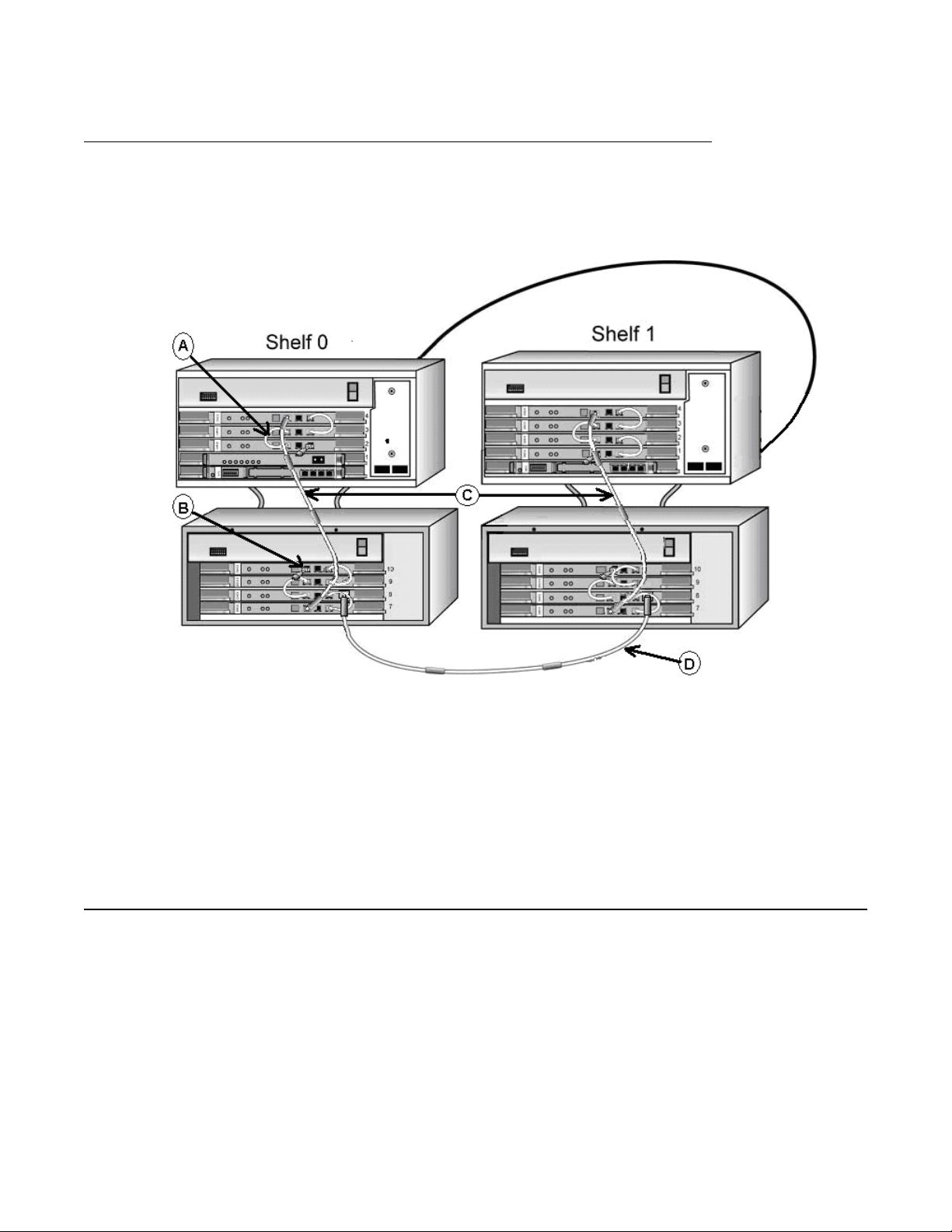
Inter-shelf faceplate connections
The following figure describes the IPE inter-shelf faceplate cabling.
DMC DECT Fundamentals August 2012 23

Product description
Figure 12: IPE inter-shelf faceplate cabling
The above figure shows:
a IPE DECT shelf 0
b IPE DECT shelf 1
c DMC-E to DMC-E faceplate cable connection between DMC-Es on DECT IPE
shelves (NTCW1
1EA)
24 DMC DECT Fundamentals August 2012
Comments? infodev@avaya.com
MG1000E Chassis faceplate cabling
The following figure describes the MG1000E Chassis faceplate cabling.
Figure 13: MG1000E Chassis faceplate cabling
Basestations
Faceplate cables shown on the figure are:
a DMC to DMC faceplate cable (NTCW11AA)
b Faceplate termination (NTCW11DA)
c DMC to DMC 1-meter faceplate cable with four ferrites (NTCW11FA)
d DMC-E to DMC-E faceplate cable connection between two shelves (NTCW11EA)
Basestations
There are three basestation models available:
C4600 – supports six active call radio links
•
• C4610 – supports 12 active call radio links
• C4610E (with external antenna) – supports 12 active call radio links
DMC DECT Fundamentals August 2012 25

Product description
Basestations are IP40-compliant wall-mounted transceivers that provide digital radio links to
handsets.
Caution:
Service Interruption
For maximum line length before signal degradation occurs, use UTP
Cat 5 cabling between
the basestation and the shelf or cabinet. If the line length exceeds 100 ohms for the 4610
basestation, an external power supply must be used. The maximum distance when using
external power with UTP Cat 5 cabling is approximately 1.7 km.
The basestation has the following features:
• RJ45 socket connection to a one meter UTP Cat 5 cable
• RJ45 socket connection to an external or local power supply
• Green LED (C4600) or a yellow LED (C4610), indicates synchronization to its DMC8
• One meter UTP Cat 5 cable connected through an RJ45 Connect Box and MDF to an
IPE I/O panel or CS 1000E cabinet I/O panel
Two sources can power the basestation:
• The DMC8 and DMC8-E feeding phantom power over the UTP Cat 5 cable signaling
pairs, connected to (a) in
•
A local power supply, connected to (b) in
Figure 14: Basestation on page 26
Figure 14: Basestation on page 26
Figure 14: Basestation
Basestations connected to a DMC8 or DMC8-E card can use phantom power in some
conditions, and must use local power in other conditions.
An application on the DMC DECT
Manager can enable or disable phantom power.
Note:
The maximum line length for a twelve-channel basestation using phantom power is 1.0 km.
The maximum line length for a six-channel basestation, regardless of power
, or a twelve-
channel basestation using external power, is 1.7 km.
26 DMC DECT Fundamentals August 2012
Comments? infodev@avaya.com

Basestation housing
Basestations
The basestation environmental housing is IP66 compliant.
if a basestation is subject to conductive pollution, or outdoors if basestations are mounted
externally.
The housing must be used indoors
Figure 15: Basestation environmental housing
The environmental housing kit includes all of the relevant cables and installation material. The
environmental housing mounts to existing walls. Signaling lines provide power to the external
basestations.
Basestation cell
basestation cell is the radio signal area covered by a single basestation. The basestations
A
are positioned so the cells overlap. A DECT handset can make and receive calls when within
a basestation cell. When the handset moves from one cell to another, the cell overlap allows
the handset to move without interruptions.
DMC DECT Fundamentals August 2012 27

Product description
Figure 16: Basestation cell
The cell radius varies from 20m to 100m.
The number of basestations required to cover a certain area depends on many factors, such
as the following:
Size of the area of coverage
•
• Radio propagation characteristics of the buildings
• Materials used for walls, floors, lift shafts, reinforced glass, doors
• Strong magnetic fields from radar, welding equipment, manufacturing equipment, and
high energy electronic devices
• Density of telephone users in an area, and amount of telephone traffic
DECT handset subscription and de-subscription
Subscription is the process of adding a handset to a DECT
make and receive calls.
system. The handset can then
A user can subscribe a handset to more than one DECT system. This feature is useful for a
company that has multiple DECT sites.
De-subscription is the process of removing a handset from a DECT system. The handset user
is then prevented from making and receiving calls.
28 DMC DECT Fundamentals August 2012
Comments? infodev@avaya.com

Note:
Refer to each DECT Handset User Guide for a detailed description of how to use handset
features and system features.
DMC DECT Manager
DMC DECT Manager
The DMC DECT
an A vaya CS system. DMC DECT Manager 2.0 runs on Windows 2000 Server , Windows 2000
Professional, Windows XP Professional, Windows Server 2003, and Windows 7.
Note:
For an overview of the DMC DECT
Communication Server 1000 (NN43001-142).
Manager provides a point of access and control to manage DECT system on
DECT Application features
The DECT
• Launch the Application from DMC DECT Manager using Windows and Web navigators
• View DECT provisioning using the DECT Systems window
• View the DMC8 configuration using the Boards window
• View basestation configuration using the Radio Fixed Part window
• View subscription information using the Subscriptions window
• Upgrade firmware using the DECT Systems window
Application allows a user to:
Manager, see Using the DMC DECT Manager Avaya
• Subscribe handsets using the Subscription window
• Support DMC8 and DMC (serial only) cards
• Synchronize (update) the DECT Application database to the DECT system configuration
when the DMC DECT Manager connects to the DECT system
• Collect performance data using the Performance Collection window
• View On-line Help
DMC DECT Fundamentals August 2012 29

Product description
Common Services
The following DECT
• DMC DECT Manager Alarm Management provides alarm collection and alarm
processing, as well as the following:
- a Windows-based alarm browser to view alarms that occur while the browser is open
- an Alarm Notification application to notify personnel of an alarm occurrence by pager
or e-mail. This application can forward the alarm to an upstream processor
- a PC Event log and Viewer to view events and alarms generated from the DECT
Application in a report layout
• Backup and restore to create and restore a DMC DECT Manager backup file of the DECT
application data
• User profiles to enable configuration of different types of DECT users
• On-line help to provide help for common services features
For more information about the Common Services features, see Using the DMC DECT
Manager Avaya Communication Server 1000 (NN43001-142).
management features are provided by DMC DECT Manager Applications:
Remote Access Service (RAS)
A
computer in a network provides access to remote users through analogue modem or ISDN
connections. The computer includes the dial-up protocols and access control (authentication),
and can be a regular file server with remote access software or a proprietary system. The
modems can be internal or external to the device.
ISDN is an international telecommunications standard for providing a digital service from the
customer's premises to the dial-up telephone network.
30 DMC DECT Fundamentals August 2012
Comments? infodev@avaya.com
Loading...