


ERS 3510GT-PWR+
Avaya ERS 3510GT-PWR+, ERS 3510GT, ERS 3524GT-PWR+, ERS 3524GT, ERS 3526T Quick Install Manual
...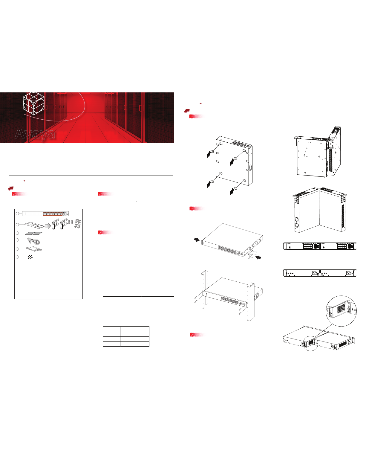
To rack mount a pair of ERS 3510GT or ERS 3510GT-PWR+ switches:
Use the 3510-Pair Rack Mount Accessory Kit (AL3511002-E6) to mount two ERS
3510GT or ERS 3510GT-PWR+ switches together side-by-side in a standard
19” rack.
Note: When mounting two 3510GT-PWR+ units side by side in an equipment rack,
run the switches in high power mode to ensure adequate airflow.
1. Ensure power is disconnected from the switch.
2. Connect the two ERS 3510GT switches together by opening the hinged bracket
to 90° and attaching it to each ERS 3510GT switch with three M4 flat head
screws (included), as shown below.
3. Attach the standard rack mount bracket ears to the outer end of each switch as
shown below.
4. Once the switches are joined together, fold the hinged bracket inward.
Steps 1 3
Before you start
Steps 4 6
Mounting Options
All documents referenced in this Quick Installation Guide can be downloaded at www.avaya.com.
Depending on your hardware model, your switch may appear different than the figures shown in this guide.
1
3
5a
5b
Rack mounting - ERS 3524GT, ERS 3524GT-PWR+,
ERS 3526T, or ERS 3526T-PWR+
Rack mounting pairs ERS 3510GT or ERS 3510GT-PWR+
2
4
1
5
6
3
3526T-PWR+
Confirm that you have the tools and package contents as follows:
Tools Required:
• Phillips #2 screwdriver
Package Contents:
1. Avaya Ethernet Routing Switch 3500 Series
2. Rack-mounting hardware that includes:
(not applicable to ERS 3510GT or ERS 3510GT-PWR+)
• Rack-mount brackets (2)
• Screws to attach brackets to the switch (8)
• Screws to attach the switch to the equipment rack (2x4)
3. Rubber footpads (ERS 3510GT and ERS 3510GT-PWR+ only)
4. AC power cord
(Note: a power cord is not included for the A variant of the switch)
5. Base Software License Kit
6. Screws (2) and wall anchors (2) for wall mounting
(ERS 3510GT and ERS 3510GT-PWR+ only)
Depending on your installation, the following accessory kits may
be required:
• One 3510-Pair Rack Mount Kit — this accessory kit is used to connect two
ERS 3510GT or ERS 3510GT-PWR+ switches together side-by-side and
mount them in a 19 inch rack. The kit includes all necessary brackets and
fasteners and must be ordered separately (Order Code AL3511002-E6)
• One Spare Rack Mount Kit – this kit can be used to mount an ERS 3510GT
or ERS 3510GT–PWR+ under a desk or on to another surface. This kit is
also used as a replacement rack mount kit for ERS 3524GT, ERS
3524GT-PWR+, ERS 3526T or ERS 3526T-PWR+ systems (Order Code
AL3511001-E6)
• One 3510-Single Rack Mount Kit – this kit is used to mount a single ERS
3510GT or ERS 3510GT-PWR+ switch in a standard 19 inch rack. Kit
includes all mounting brackets and fasteners and must be ordered
separately (Order Code AL3511003-E6)
Note: There is a Kensington Lock slot on the back of each switch. Carefully
remove the plastic plug from the hole if you need to use the K-Lock slot of an
ERS 3510GT or ERS 3510GT-PWR+ unit.
4
If you are mounting the ERS 3510GT or ERS 3510GT-PWR+ switch on a table
or shelf, attach the rubber feet to the device as indicated.
Set the device on a flat surface near an AC power source, making sure there is at
least 2 inches (5.1 cm) of space on all sides for proper air flow, and at least
5 inches (12.7 cm) at the back for power cord clearance.
If you are mounting the ERS 3524GT, ERS 3524GT-PWR+, ERS 3526T, or ERS
3526T-PWR+ switch in an equipment rack, attach the rack mount brackets to each
side of the device using the screws provided. Choose the appropriate rack-mount
for attaching the switch to your data or phone rack.
2
When you install the switch into a network, ensure you use the following cables:
• Category 5E or higher specification cabling should be used for
1 Gbps/1000 Mbps operation
• RJ-45 Console port cables as follows:
PEC code
AL2011022-E6
AL2011020-E6
AL2011021-E6
Short Description
Avaya RJ-45
CONSOLE CABLE
Avaya DB-9 RED
Avaya DB-9 BLUE
AVAYA RED DB-9 FEMALE TO
RJ-45 ADAPTOR.
Note: converts DB-9 MALE to
RJ-45 serial port. Can be used for
PC or device with DB-9 MALE
console port. Can be used with
Category 5 RJ-45 straight cable to
provide console connection.
AVAYA BLUE DB-9 MALE TO
RJ-45 ADAPTOR. Note: converts
DB-9 FEMALE to RJ-45 serial port.
Can be used to convert DB-9 of
AL2011013-E6 console cable to
RJ-45.
A Category 5 RJ-45 straight cable
can then connect to RJ-45
console port.
AVAYA RJ-45/DB-9 INTEGRATED
CONSOLE CABLE
Note: 1.5m cable with DB-9
Female for PC and RJ-45 for
device console port. This is the
recommended standard cable.
PEC code
AL3518001-E6
AL3518002-E6
AL3518003-E6
Description
46cm (1.5 ft) Stack Cable
1.5m (5 ft) Stack Cable
3m (10 ft) Stack Cable
Table/Shelf mounting
Ethernet Routing Switch 3500 Series
Quick Install Guide
Avaya
3510GTPWR+
3510GT
OFFSET BRACKET
AND SCREW DETAIL
(Optional) Prepare the rack:
a. Provide the equivalent of one rack of vertical space for each switch in an EIA or
IEC-standard 19-inch (48.2-centimeter) equipment rack.
b. Ensure that the equipment rack is stable and securely attached to a
permanent structure.
c. Ground the rack to the same grounding electrode used by the power service in
the area. The ground path must be permanent and must not exceed 1 Ohm of
resistance from the rack to the grounding electrode. AVAYA recommends using a
filter or surge suppressor.
• Stacking cables as require (see Step 7)
5. Perform one of the following:
• To connect two ERS 3510GT or two 3510GT-PWR+ switches together use
the rear bracket as shown below, with four M4 pan head screws to secure the
switches at the rear. Once the rear bracket has been installed, the switches can
be installed in the rack.
• To connect one ERS 3510GT switch and one ERS 3510GT-PWR+ switch
together use the offset rear bracket with four M4 pan head screws to join the
switches at the rear. Once the rear bracket has been installed, the switches can
be installed in the rack.
Note: If you are mounting a mix of ERS 3510GT and ERS 3510GT-PWR+ units
side by side, ensure that the ERS 3510GT unit is mounted on the LEFT side
(when viewed from the front) for adequate airflow.
a. Slide the switch into the rack. Insert and tighten the rack-mount screws.
6. Slide the switches into the rack. Insert and tighten the rack mount screws.
7. Verify that the switch is securely fastened to the rack.
 Loading...