


IP401

IP Office 2.1
Installation Manual
40DHB0002USCL Issue 10c (11th May 2004)


Installation Manual Page i
IP Office 2.1 40DHB0002USCL Issue 10c (11th May 2004)
Table Of Contents
IP Office Installation................................................................................................................... 1
Scope of Manual ........................................................................................................................2
Scope of Manual ........................................................................................................................3
IP401 Compact Office Platform................................................................................................. 5
IP401 Compact Office ................................................................................................................................ 5
IP401 Compact Office - Front View ............................................................................................................ 6
IP401 Compact Office - Rear View............................................................................................................. 7
Typical Configuration.................................................................................................................................. 8
IP403 Office Platform................................................................................................................. 9
IP403 Office................................................................................................................................................ 9
IP403 Office - Front View ......................................................................................................................... 11
IP403 Office - Rear View .......................................................................................................................... 12
Typical Configuration................................................................................................................................ 13
IP406 Office Platform............................................................................................................... 15
IP406 Office.............................................................................................................................................. 15
IP406 Office - Front View ......................................................................................................................... 16
IP406 Office - Rear View .......................................................................................................................... 17
Typical Configurations .............................................................................................................................. 18
IP412 Office Platform............................................................................................................... 21
IP412 Office.............................................................................................................................................. 21
IP412 Office - Front View ......................................................................................................................... 22
IP412 Office - Rear View .......................................................................................................................... 23
Scenario 1 ................................................................................................................................................ 24
Scenario 2 ................................................................................................................................................ 25
Expansion Modules ................................................................................................................. 27
IP400 Digital Terminal 16/30 .................................................................................................................... 27
IP400 Digital Stations 16/30 ..................................................................................................................... 28
IP400 Phone 8/16/30................................................................................................................................ 28
IP400 So8................................................................................................................................................. 29
IP400 WAN3............................................................................................................................................. 30
IP400 Analog Trunk 16............................................................................................................................. 31
Country Variants ...................................................................................................................... 33
Overview of Country Variants................................................................................................................... 33
IP400 Office Systems ............................................................................................................................... 34
Integral Module Kits.................................................................................................................................. 35
Trunk Module Kits..................................................................................................................................... 36
Power Supplies......................................................................................................................................... 37
IP Office Rack Mounting Kits.................................................................................................................... 37
Expansion Modules .................................................................................................................................. 38
Preparing for Installation......................................................................................................... 39
Preparing for Installation........................................................................................................................... 39
Tools & Parts Required ............................................................................................................................ 39
Space requirements ................................................................................................................................. 40
Environmental requirements..................................................................................................................... 41
Power Supply requirements ..................................................................................................................... 42
Grounding................................................................................................................................................. 43
Grounding ............................................................................................................................................ 43
Protective Ground ................................................................................................................................ 43
Functional Ground ............................................................................................................................... 44
Out of Building Telephone Installations .................................................................................................... 45

Table Of Contents
Installation Manual Page ii
IP Office 2.1 40DHB0002USCL Issue 10c (11th May 2004)
Out of Building Telephone Installations ............................................................................................... 45
Rack Mounting Barrier Boxes .............................................................................................................. 46
Installing a New System .......................................................................................................... 49
Unpacking................................................................................................................................................. 49
Trunk Interface Modules (BRI/PRI/ANALOG4) ........................................................................................ 50
Installation of Voice Compression Modules (VCM) .................................................................................. 51
Dual Modem Module ................................................................................................................................ 52
Rack Mounting Assembly Instructions...................................................................................................... 53
IP401 Expansion and Installation of Integral Modules.............................................................................. 54
IP401 Compact Office Wall Mounting....................................................................................................... 55
Initial Assembly......................................................................................................................................... 56
Basic System Programming ................................................................................................... 57
Introduction............................................................................................................................................... 57
Programming Tools .................................................................................................................................. 58
Programming Tools.............................................................................................................................. 58
PC to IP Office LAN Port Connection .................................................................................................. 58
Initial Programming................................................................................................................................... 59
Initial Programming .............................................................................................................................. 59
Using the IP Office Installation Wizard:................................................................................................ 60
Using the IP Office Manager Application: ............................................................................................ 60
Software Upgrades................................................................................................................................... 61
Software Upgrades .............................................................................................................................. 61
Upgrading an IP403 to Software Level 2.1 .......................................................................................... 63
Telephone Installation ............................................................................................................. 65
Checking Telephones............................................................................................................................... 65
Checking Telephones .......................................................................................................................... 65
Connecting & Testing IP Office Telephones ........................................................................................ 65
Connecting & Checking Two-Wire Telephones ................................................................................... 66
Power Fail Telephones and Sockets ................................................................................................... 66
Wall Mounting 2000 Series Telephones................................................................................................... 67
Wall Mounting 44/4600, 2420 & 6400 Series Telephones ....................................................................... 68
System Handover..................................................................................................................... 69
Checklist ................................................................................................................................................... 69
Safety and Homologation Statements.................................................................................... 71
Safety and Homologation Statements ...................................................................................................... 71
Lithium Batteries....................................................................................................................................... 71
Lightning Protection/Hazard Symbols ...................................................................................................... 71
Electromagnetic Interference Information................................................................................................. 72
Federal Communications Commission (FCC) ..................................................................................... 72
Canadian Department of Communications (DOC)............................................................................... 72
Trunk Interface Modules........................................................................................................................... 73
USA/Canada ........................................................................................................................................ 73
Rest Of World (ROW) .......................................................................................................................... 73
Further Information and Product Updates ................................................................................................ 74
Further Information and Product Updates............................................................................................ 74
Support Telephone Numbers............................................................................................................... 74
Regulatory Instructions for Use ................................................................................................................ 75
Regulatory Instructions for Use............................................................................................................ 75
IP Office Operation in Australia............................................................................................................ 75
Industry Canada Notification (DoC) ..................................................................................................... 76
IP Office Operation in EU..................................................................................................................... 76
IP Office Operation in New Zealand .................................................................................................... 76
IP Office Operation in USA .................................................................................................................. 77
Technical Data.......................................................................................................................... 79
Port Pinouts .............................................................................................................................................. 79

Table Of Contents
Installation Manual Page iii
IP Office 2.1 40DHB0002USCL Issue 10c (11th May 2004)
Port Pinouts ......................................................................................................................................... 79
Analog Trunk Ports (RJ45) .................................................................................................................. 79
Power Fail and POT Ports (RJ45) ....................................................................................................... 79
DS/DT Ports (RJ45) ............................................................................................................................. 79
ISDN Port – BRI (RJ45) ....................................................................................................................... 80
ISDN Port – PRI (RJ45) ....................................................................................................................... 80
LAN Port – 10/100 BaseT .................................................................................................................... 80
DTE Port (25 Way or 9 Way D-Type socket) ....................................................................................... 81
Audio Port (3.5mm Stereo Jack Socket).............................................................................................. 81
Expansion Port (RJ45 Socket)............................................................................................................. 81
External Control Port (3.5mm Stereo Jack Socket) ............................................................................. 82
WAN Port (37 Way D-Type Socket)..................................................................................................... 83
Cables ...................................................................................................................................................... 84
Cables.................................................................................................................................................. 84
DTE Cable ........................................................................................................................................... 84
DT Line Cord for Structured Cabling.................................................................................................... 85
PRI/BRI ISDN Cable ............................................................................................................................ 86
LAN Interconnect Cable....................................................................................................................... 87
LAN Cable............................................................................................................................................ 88
LAN Crossover Cable .......................................................................................................................... 89
Expansion Interconnect Cable ............................................................................................................. 90
V.24/V.28 WAN Cable ......................................................................................................................... 91
X.21 WAN Cable.................................................................................................................................. 92
V.35 WAN Cable.................................................................................................................................. 93
Telephone Converter Cables ............................................................................................................... 94
Port Safety Classification.......................................................................................................................... 95
Port Safety Classification ..................................................................................................................... 95
Compliance with FCC Rules ................................................................................................................ 96
Technical Specifications ........................................................................................................................... 97
General ................................................................................................................................................ 97
Interfaces ............................................................................................................................................. 98
Protocols .............................................................................................................................................. 99
Internal Data Channels ...................................................................................................................... 100
SNMP....................................................................................................................................... 101
SNMP Functionality ................................................................................................................................ 101
SNMP Agent Configuration .................................................................................................................... 101
MIBs Supported...................................................................................................................................... 102
Trap Generation ..................................................................................................................................... 103
MIB Loading ........................................................................................................................................... 104
HP OpenView Network Node Manager 6.41 and earlier: ....................................................................... 104
CastleRock SNMPc 5.1.6c and earlier: .................................................................................................. 105
Index........................................................................................................................................ 107


Installation Manual Page 1
IP Office 2.1 40DHB0002USCL Issue 10c (11th May 2004)
IP Office Installation
This manual covers the installation of your Avaya IP401/403/406/412 Office equipped with software
release Level 1.0+ through to 2.1. It is intended for use by installers and maintainers who have
successfully completed the appropriate IP Office training courses.
• Ensure that you have read and understood this manual before beginning installation.
For installation instructions for the Avaya IP Office - Small Office Edition, refer to the separate Small
Office Edition Installation Manual.

IP Office Installation
Installation Manual Page 2
IP Office 2.1 40DHB0002USCL Issue 10c (11th May 2004)
Scope of Manual
This manual, for Avaya IP Office systems, covers the following subjects and should be read in the
sequence shown below:
• Avaya IP Office Platforms
This section provides details of the various Avaya IP Office platforms available. Illustrations of the
front and rear of each unit show what ports/sockets/etc are provided. Typical configuration
examples are also provided in this section. A further section details the country variants of
modules/trunks/integral modules/etc.
• Preparing for and Installing a new system
These sections provide all the information required and the actions to be performed to physically
install an IP Office, i.e. what tools are required, the environmental/power requirements, wall
mounting, rack mounting, etc. The software installation is covered in the following section.
• Basic System Programming
System programming is necessary for configuration and maintenance of the Avaya IP Office.
This manual only covers the installation of the IP Office suite of programs. For full details refer to
the Installation Wizard Help files and/or to the Manuals contained on the documentation CD
(supplied with every unit).
• Terminal/Telephone Installation
This manual details the information required to install telephone but does not detail the usage
and functionality of IP Office terminals/telephones. These details are to be found in the
appropriate User Guides. The terminals/telephones that are supported by the IP Office are (these
are also used across a number of Avaya platforms:
• Avaya 2000 Series: 20AT, 20CC, 2010, 2030, 2050, 20DSS/BLF and 20DT.
• Avaya 2400 Series: 2420.
• Avaya 3600 Series: 3616, 3626.
• Avaya 4400 Series: 4406D, 4412D, 4424D and 4450DSS*.
• Avaya 4600 Series: 4602, 4602SW, 4620, 4606, 4612 and 4624.
• Avaya 6400 Series: 6408D+, 6416D+M, 6424D+M and XM24 (DSS).
• *Caution: See DT Line Cord for Structured Cabling for wiring details on a
4450DSS module.
• Safety and Homologation Statements
This provides all the necessary Safety, Homologation Statements and Regulatory Instructions for
Use required. This section also detail where further information, including other Manuals and
support telephone numbers, can be obtained
• Technical Data
This manual contains information on the Port Pinouts/Safety classifications, cables, and basic
technical specifications only (see Technical Specifications). Descriptions of the functionality,
features and performance of the IP Office are covered by the Product Description.

Installation Manual Page 3
IP Office 2.1 40DHB0002USCL Issue 10c (11th May 2004)
Scope of Manual
This manual, for Avaya IP Office systems, covers the following subjects and should be read in the
sequence shown below:
• Avaya IP Office Platforms
This section provides details of the various Avaya IP Office platforms available. Illustrations of the
front and rear of each unit show what ports/sockets/etc are provided. Typical configuration
examples are also provided in this section. A further section details the country variants of
modules/trunks/integral modules/etc.
• Preparing for and Installing a new system
These sections provide all the information required and the actions to be performed to physically
install an IP Office, i.e. what tools are required, the environmental/power requirements, wall
mounting, rack mounting, etc. The software installation is covered in the following section.
• Basic System Programming
System programming is necessary for configuration and maintenance of the Avaya IP Office.
This manual only covers the installation of the IP Office suite of programs. For full details refer to
the Installation Wizard Help files and/or to the Manuals contained on the documentation CD
(supplied with every unit).
• Terminal/Telephone Installation
This manual details the information required to install telephone but does not detail the usage
and functionality of IP Office terminals/telephones. These details are to be found in the
appropriate User Guides. The terminals/telephones that are supported by the IP Office are (these
are also used across a number of Avaya platforms:
• Avaya 2000 Series: 20AT, 20CC, 2010, 2030, 2050, 20DSS/BLF and 20DT.
• Avaya 2400 Series: 2420.
• Avaya 3600 Series: 3616, 3626.
• Avaya 4400 Series: 4406D, 4412D, 4424D and 4450DSS*.
• Avaya 4600 Series: 4602, 4602SW, 4620, 4606, 4612 and 4624.
• Avaya 6400 Series: 6408D+, 6416D+M, 6424D+M and XM24 (DSS).
• *Caution: See DT Line Cord for Structured Cabling for wiring details on a
4450DSS module.
• Safety and Homologation Statements
This provides all the necessary Safety, Homologation Statements and Regulatory Instructions for
Use required. This section also detail where further information, including other Manuals and
support telephone numbers, can be obtained
• Technical Data
This manual contains information on the Port Pinouts/Safety classifications, cables, and basic
technical specifications only (see Technical Specifications). Descriptions of the functionality,
features and performance of the IP Office are covered by the Product Description.


Installation Manual Page 5
IP Office 2.1 40DHB0002USCL Issue 10c (11th May 2004)
IP401 Compact Office Platform
IP401 Compact Office
The IP401 Compact Office system platform is supplied in two variants:
• IP401 Compact Office 2 supports: Two digital and two analog telephones A BRI ISDN port (2
trunks) An four port auto-negotiating 10/100 BaseT LAN hub.
• IP401 Compact Office 4 supports: Four digital and four analog telephones Two BRI ISDN
ports (4 trunks) An eight port auto-negotiating 10/100 BaseT LAN hub. The IP401 Compact
Office 2 can be expanded to an IP401 Compact Office 4.
See IP400 Office Systems
for country specific variants.
The auto-negotiating 10/100 BaseT LAN hub provides access to networks and/or up to eight IP
telephones.
The DT ports support Avaya 2000 series telephones. DT ports are set to A-Law PCM encoding at default
but can be programmed to -Law PCM encoding.
In addition the IP401 Compact Office can be fitted with any of the following optional Integral Modules:
• WAN Port
This port supports a single synchronous data connection, which can be X.21, V.35 or V.24.
• Voice Compression Module (VCM5)
Supports VoIP applications (over two of the five channels) using Avaya 4600 IP telephones
connected via LAN ports.
• VME card
Provides memory capacity for embedded voice mail feature.
IP Office Installation
Installation Manual Page 6
IP Office 2.1 40DHB0002USCL Issue 10c (11th May 2004)
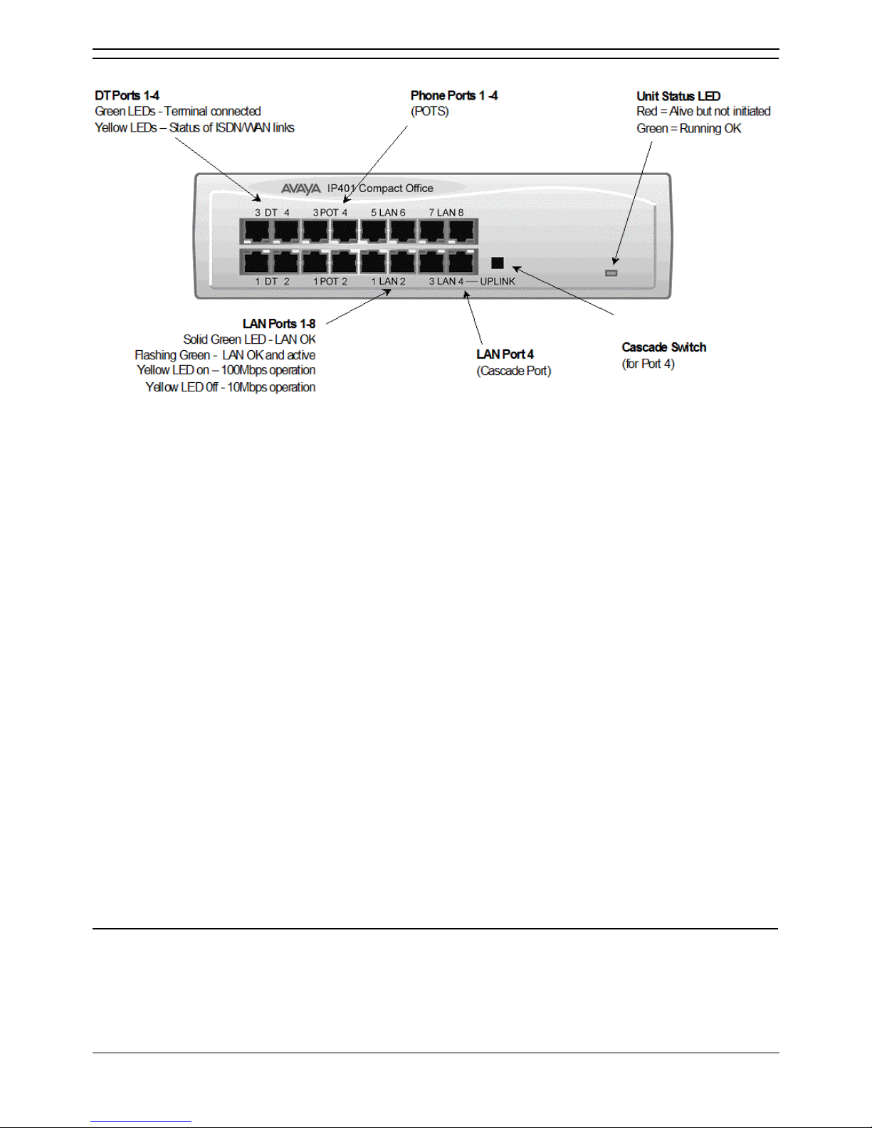
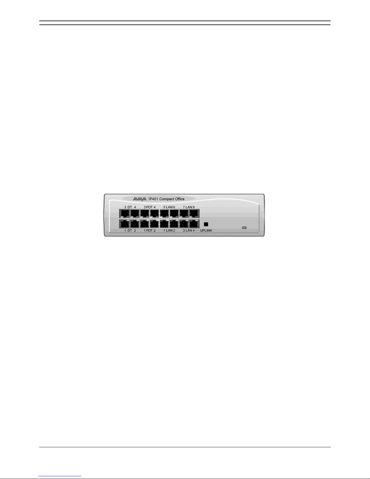
IP401 Compact Office - Front View
• Note
The IP Compact Office DT4 is shown above. The IP Compact Office DT2 does not have
the top row (labeled 3 DT 4, 3 POT 4, 5 LAN 6 and 7 LAN 8) of RJ45 ports fitted.
• DT Ports
DT ports are used for connection to Avaya 2000 series telephones and support either A-Law or Law PCM encoding (default A-Law). Using DT Line Cords and standard structured wiring, these
RJ45 ports can be extended to the required telephone location. In addition, converters can be
used to provide BT New Plan sockets (431A/631A) if required. When telephones are equipped
with line cords that terminate in RJ11 plugs, then pin-to-pin RJ11/RJ45 adapters should be used.
• Plain Ordinary Telephone (POT) Ports
These ports are used for connection to standard analog telephones, fax machines and modems.
These ports must not be used for connection to trunks. Using standard structured wiring, these
RJ45 ports can be extended to the required telephone location. Converters can be used to
provide BT New Plan sockets (431A/631A) if required. When telephones are equipped with line
cords that terminate in RJ11 plugs, then pin-to-pin RJ11/RJ45 adapters should be used.
• LAN Ports
The auto-negotiating 10/100 BaseT LAN hub ports are used for PC and server connectivity. They
can also be used to connect to IP telephones (Avaya 4600 IP series).
• LAN ports allow information relating to incoming and outgoing telephone calls to be
forwarded to PC based applications. They also provide access to the router
functionality/configuration of the IP401 Compact Office platform for both data and Voice
over IP (VoIP) calls. The auto-negotiating 10/100 BaseT LAN hub ports support a single
MAC address only (printed on base of unit).
• Where more than eight LAN connections are required, the fourth LAN port can be used
for cascading to other hubs. The Uplink push button to the right of this port is used to set
the mode. When the Uplink switch is in the out position the port can be connected to
another hub without the need for a crossover cable, i.e. the port is an MDI type port.
When the Uplink switch is in the in position the port can be connected directly to a PC.
Cables
IP401 Compact Office 2 is supplied with one red CAT5E cable. The Compact Office 4 is supplied with
two red CAT5E cables.
IP401 Compact Office Platform
Installation Manual Page 7
IP Office 2.1 40DHB0002USCL Issue 10c (11th May 2004)
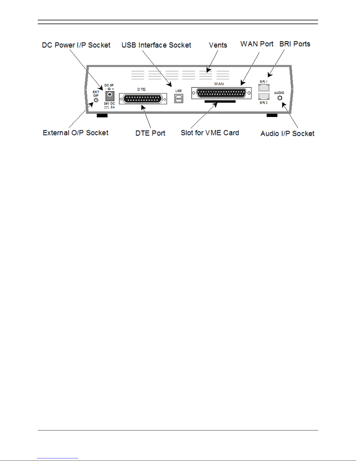
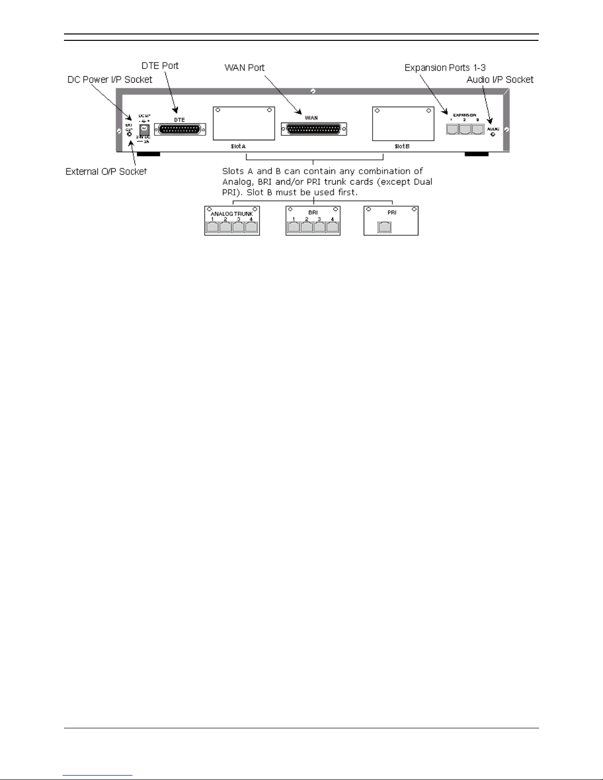
IP401 Compact Office - Rear View
• Notes:
1. The IP401 Compact Office 4 is shown above; the WAN port is optional.
2. On an IP401 Compact Office 2, the WAN port is optional and BRI 1 is not fitted.
3. The IP401 Compact Office can be wall mounted.
• External O/P Socket
Allows externally powered circuits to be controlled via a single 3.5mm stereo jack socket.
• DC Power I/P Socket
Socket for the external 24V DC unregulated power supply (supplied with kit).
• DTE Port
A 25-way D-type socket. Used for connection to PCs, servers and EFTPOS terminals.
• BRI Ports
Two BRI trunk interface ports are fitted on an IP401 Compact Office 4 and only one on an IP401
Compact Office 2; providing four and two trunks respectively. See IP401 Expansion and
Installation of Integral Modules for expansion and IP400 Office Systems for country specific
variants.
• WAN Port
This port supports a single synchronous data connection, which can be X.21, V.35 or V.24. The
selection of the required interface is automatically determined from the pin-out of the cable
plugged into the 'WAN' port. This cable must be connected before power is applied for auto
detection to work. Connection to a Digital Leased Circuit is made by connecting the WAN port on
the rear of the unit to the existing Network Terminating Unit (NTU) via the appropriate X.21, V.35
or V.24 cable.
• USB Interface
Not used.
• Audio I/P Socket
A single 3.5mm stereo or mono jack socket that enables input from an external 'Music-on-Hold'
source.
IP Office Installation
Installation Manual Page 8
IP Office 2.1 40DHB0002USCL Issue 10c (11th May 2004)
Typical Configuration
Scenario
A customer requiring a voice and data solution for a warehousing facility remote from a regional office.
Three administrators and two pickers staff the warehouse.
This configuration provides support for four Avaya 2000 series digital telephones, one for each of the
administrators, leaving a spare port for future growth. Up to four analog telephones (POTS), two of which
support a DECT wireless solution to allow the pickers freedom of movement, with one of the remaining
ports being used for a fax machine.
The eight port 10/100M Hub allows the local PCs and Printers to be networked. Connectivity for all voice
and data traffic between the Warehouse and the regional office is carried over the optional IP401 WAN
interface using Voice over IP and standards based compression (through the optional IP400 VCM 5
media card). Two ISDN ports allow up to four simultaneous calls to the public network.
Kit List
• IP401 Compact Office DT4
• IP401 Compact Office WAN Expansion
• IP400 Office Voice Compression Module 5
• 2 x 2030 Display Terminals

Installation Manual Page 9
IP Office 2.1 40DHB0002USCL Issue 10c (11th May 2004)
IP403 Office Platform
IP403 Office
The IP403 Office base unit supports up to eight digital and two analog telephones. This can be
expanded, by use of 3 additional extension modules, to a max. of 100 extensions. Two variants are
available and are equipped as follows:
• DT ports - support Avaya 2000 series telephones.
• DS ports - support Avaya 6400, 2420 series and/or Avaya 4400 series telephones.
Both ports can be set for either -Law or A-Law PCM encoding. At default DT ports are set to A-Law and
DS ports are set to -Law. However, these can be switched in software (refer to the Administration
Manager Manual for details).
Connection to trunks is via one of the following integral interface modules:-
• Single PRI E1 (30 trunks) or Single PRI T1 (23B+1D or 24B trunks - USA only) or
• Quad BRI (8 trunks) or Analog 4 (loop start trunks).
• If Analog 4 modules are used, a second module can be fitted in Slot A.
See IP400 Office Systems
for country specific variants.
An eight port auto-negotiating 10/100 BaseT LAN hub provides access to networks and/or up to eight IP
telephones. (Where IP telephones are to be used, the hub should be connected to a suitable LAN switch
with QoS capabilities.)

IP Office Installation
Installation Manual Page 10
IP Office 2.1 40DHB0002USCL Issue 10c (11th May 2004)
Expansion Modules
Optional Expansion Modules allow the IP403 Office to be expanded to 100 extensions. These modules
(with the exception of the WAN3) are connected via the Expansion Port sockets that are located on the
back of each unit. Up to 3, in any combination, of the following Expansion Modules can be supported
by the IP403 Office base unit.
• IP400 Digital Terminal 16/30 or Digital Station 16/30
Two variants of both (16 or 30 extensions) for digital telephones. Hence, if all 3 extension
modules are IP400 Digital Terminal/Station 30s, then the maximum of 100 extensions will consist
of 90 digital extensions, plus the base unit's 2 analog extensions and 8 digital extensions.
• IP400 Phone 8/16/30
Three variants (8, 16 or 30 extensions) for analog telephones. Hence, if all 3 extension modules
are IP400 Phone 30s, then the maximum of 100 extensions will consist of 90 analog extensions,
plus the base unit's 2 analog extensions and 8 digital extensions.
• IP400 So8
An S-bus module that provides 8 Basic Rate ISDN interfaces.
• IP400 WAN3
Provides support for a further 3 digital leased line (WAN) connections. These expansion modules
are connected to the IP403 Office unit via one of the LAN Ports located on the front of each unit.
• IP400 Analog Trunk 16
Provides support for up to 16 Loop Start or Ground Start analog trunks. Two power fail sockets
are also provided.
Integral Modules (Optional)
In addition the IP403 Office can be fitted with either or both of the following optional Integral Modules:
• Voice Compression Module (VCM)
Supports VoIP applications including trunking and support for IP telephones. Available in 5,10
and 20 channel variants.
• Dual Modem Module
Allows termination of two simultaneous analog modem calls up to and including 56kbps.
IP403 Office Platform
Installation Manual Page 11
IP Office 2.1 40DHB0002USCL Issue 10c (11th May 2004)
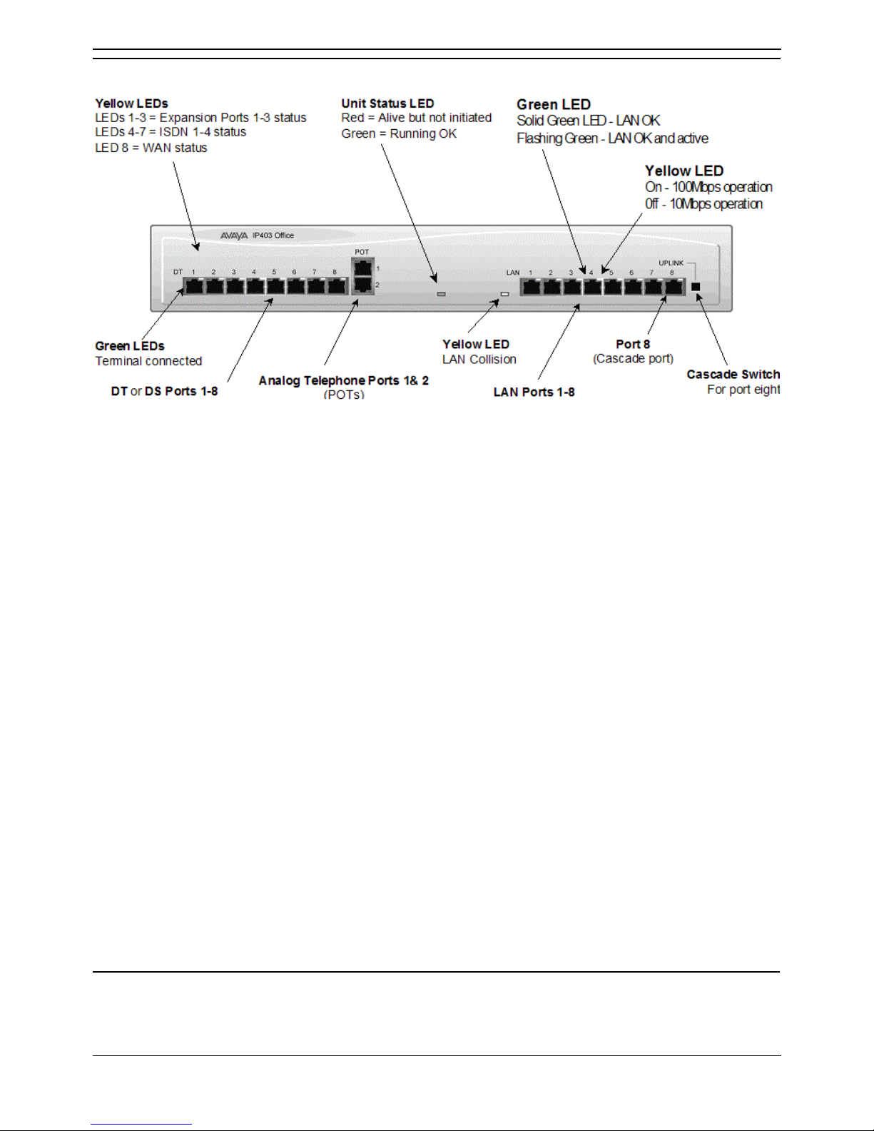
IP403 Office - Front View
• DT/DS Ports
• DT ports are for connection to Avaya 2000 series telephones.
• DS ports are for connection to Avaya 4400, 2420 and/or 6400 series telephones.
• At default DT ports are set to A-Law PCM encoding and DS ports to either A-Law or -Law
PCM encoding . However, both ports can be switched in software - refer to the
Administration Manager Manual for details). Using DT Line Cords and standard structured
wiring, these RJ45 ports can be extended to the required telephone location. In addition,
converters can be used to provide BT New Plan sockets (431A/631A) if required. When
telephones are equipped with line cords that terminate in RJ11 plugs, then pin-to-pin
RJ11/RJ45 adapters should be used.
• Plain Ordinary Telephone (POTS) Ports
These two ports are used for connection to standard analog telephones, fax machines and
modems. They must not be connect to trunks. Using standard structured wiring, these RJ45
ports can be extended to the required telephone location. Converters can be used to provide BT
New Plan sockets (431A/631A) if required. When devices are equipped with line cords that
terminate in RJ11 plugs, then pin-to-pin RJ11/RJ45 adapters should be used.
• LAN Ports
The eight auto-negotiating 10/100 BaseT LAN hub ports are used for PC and server connectivity.
They can also be used to connect to the optional IP400 WAN3 Expansion Module and IP
telephones. LAN ports allow information relating to incoming and outgoing telephone calls to be
forwarded to PC based applications. They also provide access to the router
functionality/configuration of the IP403 Office platform for both data and Voice over IP (VoIP)
calls. (Where IP telephony is required, a suitable switch LAN switch with QoS capabilities.) This
eight port auto-negotiating 10/100 BaseT LAN hub has a single MAC address (printed on the
base of the unit). Where more than eight LAN connections are required, the eighth LAN port can
be used for cascading to other hubs. The Uplink push button to the right of this port is used to
set the mode. When the Uplink switch is in the out position the port can be connected to another
hub without the need for a crossover cable, i.e. the port is an MDI type port. When the Uplink
switch is in the in position the port can be connected directly to a PC.
Cables
IP403 Office DT PRI 30 E1 & DS PRI 24 T1 are supplied with one red CAT5E cable. IP403 Office DT
BRI 8 & DS Analog 4 are supplied with four red CAT5E cables.
IP Office Installation
Installation Manual Page 12
IP Office 2.1 40DHB0002USCL Issue 10c (11th May 2004)
IP403 Office - Rear View
• External O/P Socket
Two relay ports that allow externally powered circuits to be controlled via a single 3.5mm stereo
jack socket.
• DC Power I/P Socket
Socket for the external 24V DC unregulated power supply (supplied with equipment).
• DTE Port
A 25-way D-type socket. Used for connection to PCs, servers and EFTPOS devices or terminals.
• Slot A/Slot B: BRI/PRI/ALOG Ports
The trunk interface modules are fitted into either Slots A or B and can consist of any combination
of:
• Quad Analog - 4 trunks.
• PRI E1/PRI E1-R2: 30 trunks.
• PRI T1: 24B trunks or 23B+1D trunks.
PRI T1 trunks support both ISDN and Analog emulation. The default setting is 23B+1D
and is switchable in the installation software to provide 24B trunks.
• Quad BRI: 8 trunks.
• WAN Port
This port supports a single synchronous data connection, which can be X.21, V.35 or V.24. The
selection of the required interface is automatically determined from the pin-out of the cable
plugged into the 'WAN' port. This cable must be connected before power is applied for auto
detection to work. Connection to a Digital Leased Circuit is made by connecting the WAN port on
the rear of the unit to the existing Network Terminating Unit (NTU) via the appropriate X.21, V.35
or V.24 cable. This interface is identical to those on the WAN3 Expansion Module.
• USB Interface: Not used.
• Expansion Ports 1-3: Used to provide access to the optional Expansion Moduleswhich allow
the IP403 Office to be expanded to 100 extensions.
• Audio I/P Socket: A single 3.5mm stereo or mono jack socket that enables input from an
external 'Music-on-Hold' source.
IP403 Office Platform
Installation Manual Page 13
IP Office 2.1 40DHB0002USCL Issue 10c (11th May 2004)
Typical Configuration
Scenario
A customer with sophisticated telephony requirements, needing 30 exchange lines and 80 Display
Terminals.
This configuration provides support for 98 Avaya 20 series digital telephones (18 spare for growth) and a
single Primary Rate ISDN connection. If growth beyond 18 users or additional line capacity were
anticipated, the IP406 Office would be considered more appropriate. Typically, a business of this size
would have a data network built using LAN switches such as the Avaya Cajun range. The IP403
Compact Office would be connected to the data network through its integral 8 port Hub, providing all
users access to the Internet and IP Office productivity applications.
Kit List
• IP403 Office DT PRI 30 E1
• 3 x IP400 Digital Terminal Module 30
• 80 x 2030 Display Terminals


Installation Manual Page 15
IP Office 2.1 40DHB0002USCL Issue 10c (11th May 2004)
IP406 Office Platform
IP406 Office
The IP406 Office base unit supports up to 180 extensions by using up to 6 Expansion modules.
Connection to trunks is via any two of the following integral interface modules as follows:-
• Single PRI E1/PRI E1-R2 (30 trunks) or
• Single PRI T1 (23B+1D or 24B trunks - USA only) or
• Quad BRI (8 trunks) or
• Analog 4 (loop start).
See IP400 Office Systems
for country specific variants.
An eight port auto-negotiating 10/100 BaseT LAN hub provides access to networks and/or up to eight IP
telephones. (Where IP telephones are to be used a suitable LAN switch with QoS capabilities, should be
used).
Expansion Modules
Optional Expansion Modules allow the IP406 Office to be expanded to 180 extensions. These modules
(with the exception of the WAN3 – see below) are connected via the Expansion Port sockets that are
located on the back of each unit.
Up to six, in any combination, of the following Expansion Modules can be supported by the IP406
Office base unit.
• IP400 Digital Terminal 16/30 or Digital Station 16/30
Two variants of both (16 or 30 extensions) for digital telephones. Hence, six IP400 Digital
Terminal/Station 30s will allow a maximum of 180 digital extensions.
• IP400 Phone 8/16/30
Three variants (8, 16 or 30 extensions) for analog telephones. Hence, six IP400 Phone 30s will
allow a maximum of 180 analog extensions.
• IP400 So8
An S-bus module that provides 8 Basic rate ISDN interfaces.
• IP400 WAN3
Provides support for a further 3 digital leased line (WAN) connections. These expansion modules
are connected to the IP403 Office unit via one of the LAN Ports located on the front of each unit.
• IP400 Analog Trunk 16
Provides support for up to 16 Loop Start or Ground Start analog trunks. Two power fail sockets
are also provided.
Integral Modules (Optional)
In addition the IP406 Office can be fitted with either or both of the following optional Integral Modules:
• Voice Compression Module (VCM)
Supports VoIP applications including trunking and support for IP telephones. Available in 5, 10
and 20 channel variants.
• Dual Modem Module
Allows termination of two simultaneous analog modem calls up to and including 56kbps.
IP Office Installation
Installation Manual Page 16
IP Office 2.1 40DHB0002USCL Issue 10c (11th May 2004)
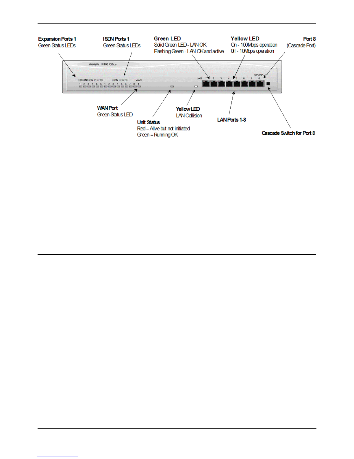
IP406 Office - Front View
• LAN Ports
The eight auto-negotiating 10/100 BaseT LAN hub ports are used for PC and server connectivity.
They can also be used to connect to the optional IP400 WAN3 Expansion Module and IP
telephones.
• LAN ports allow information relating to incoming and outgoing telephone calls to be
forwarded to PC based applications. They also provide access to the router
functionality/configuration of the IP406 Office platform for both data and Voice over IP
(VoIP) calls. (Where IP telephony is required, the hub must be connected to a suitable
LAN switch with QoS capabilities.) This eight port auto-negotiating 10/100 BaseT LAN
hub supports a single MAC address only (printed on the base of the module).
• Where more than eight LAN connections are required, the eighth LAN port can be used
for cascading to other hubs. The Uplink push button to the right of this port is used to set
the mode. When the Uplink switch is in the out position the port can be connected to
another hub without the need for a crossover cable, i.e. the port is an MDI type port.
When the Uplink switch is in the in position the port can be connected directly to a PC.
Cables
IP406 Office PRI 30 E1 & PRI 24 T1 are supplied with one red CAT5E cable. IP406 Office Analog 4 is
supplied with four red CAT5E cables. IP406 Office BRI 16 is supplied with eight red CAT5E cables.
IP406 Office Platform
Installation Manual Page 17
IP Office 2.1 40DHB0002USCL Issue 10c (11th May 2004)
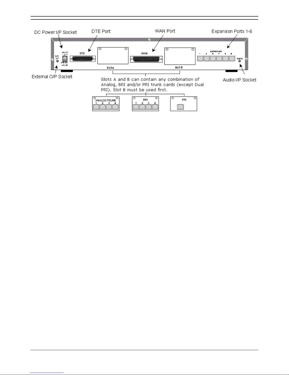
IP406 Office - Rear View
• External O/P Socket
Two relay ports that allow externally powered circuits to be controlled via a single 3.5mm stereo
jack socket.
• DC Power I/P Socket
Socket for the external 24V DC unregulated power supply (supplied with kit).
• DTE Port
A 25-way D-type socket. Used for connection to PCs, servers and EFTPOS terminals.
• Slot A/Slot B: BRI/PRI/ALOG Ports
The trunk interface modules are fitted into either Slots A or B and can consist of any combination
of:
• Quad Analog - 4 trunks.
• PRI E1/PRI E1-R2: 30 trunks.
• PRI T1: 24B trunks or 23B+1D trunks.
PRI T1 trunks support both ISDN and Analog emulation. The default setting is 23B+1D
and is switchable in the installation software to provide 24B trunks.
• Quad BRI: 8 trunks.
• WAN Port
This port supports a single synchronous data connection, which can be X.21, V.35 or V.24. The
selection of the required interface is automatically determined from the pin-out of the cable
plugged into the 'WAN' port. This cable must be connected before power is applied for auto
detection to work. Connection to a Digital Leased Circuit is made by connecting the WAN port on
the rear of the unit to the existing Network Terminating Unit (NTU) via the appropriate X.21, V.35
or V.24 cable. This interface is identical to those on the WAN3 Expansion Module.
• Expansion Ports 1-6
Used to provide access to the optional Expansion Modules which allow the IP406 Office to be
expanded to 180 extensions.
• Audio I/P Socket
A single 3.5mm stereo or mono jack socket that enables input from an external 'Music-on-Hold'
source.
IP Office Installation
Installation Manual Page 18
IP Office 2.1 40DHB0002USCL Issue 10c (11th May 2004)
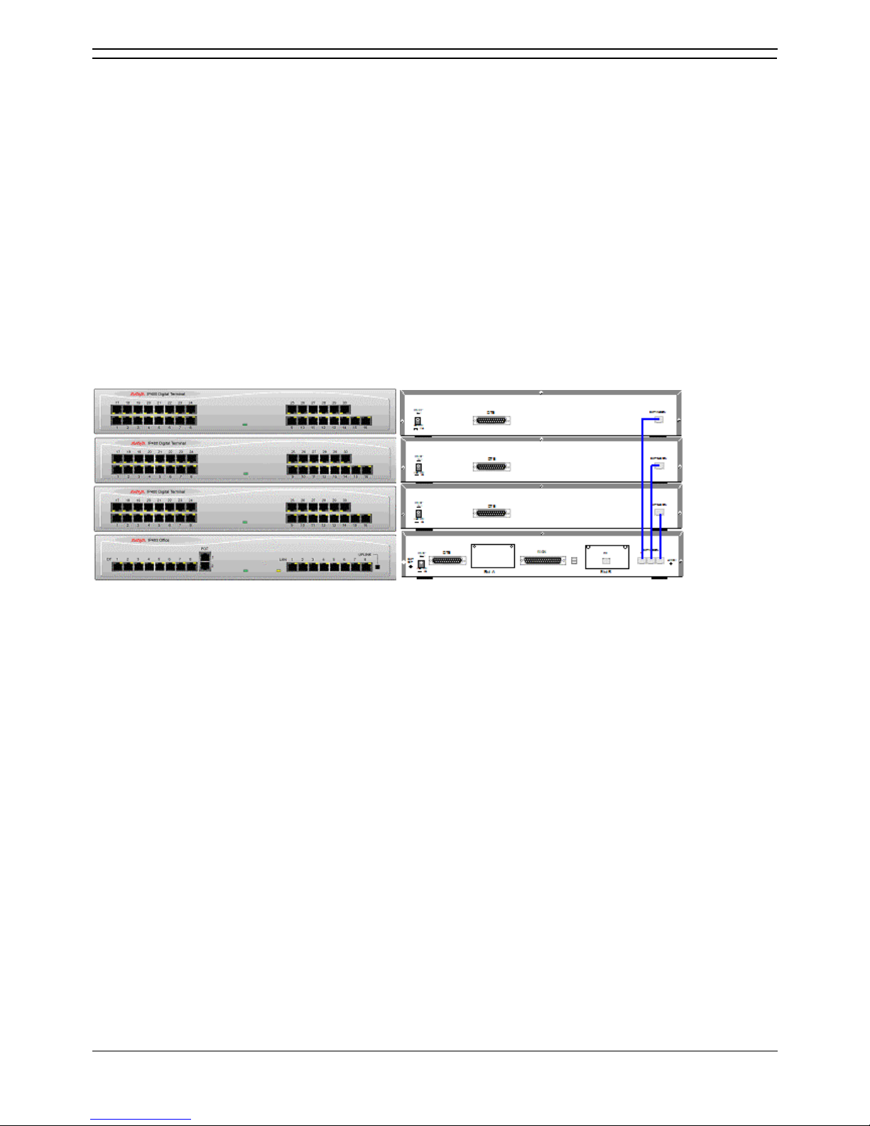
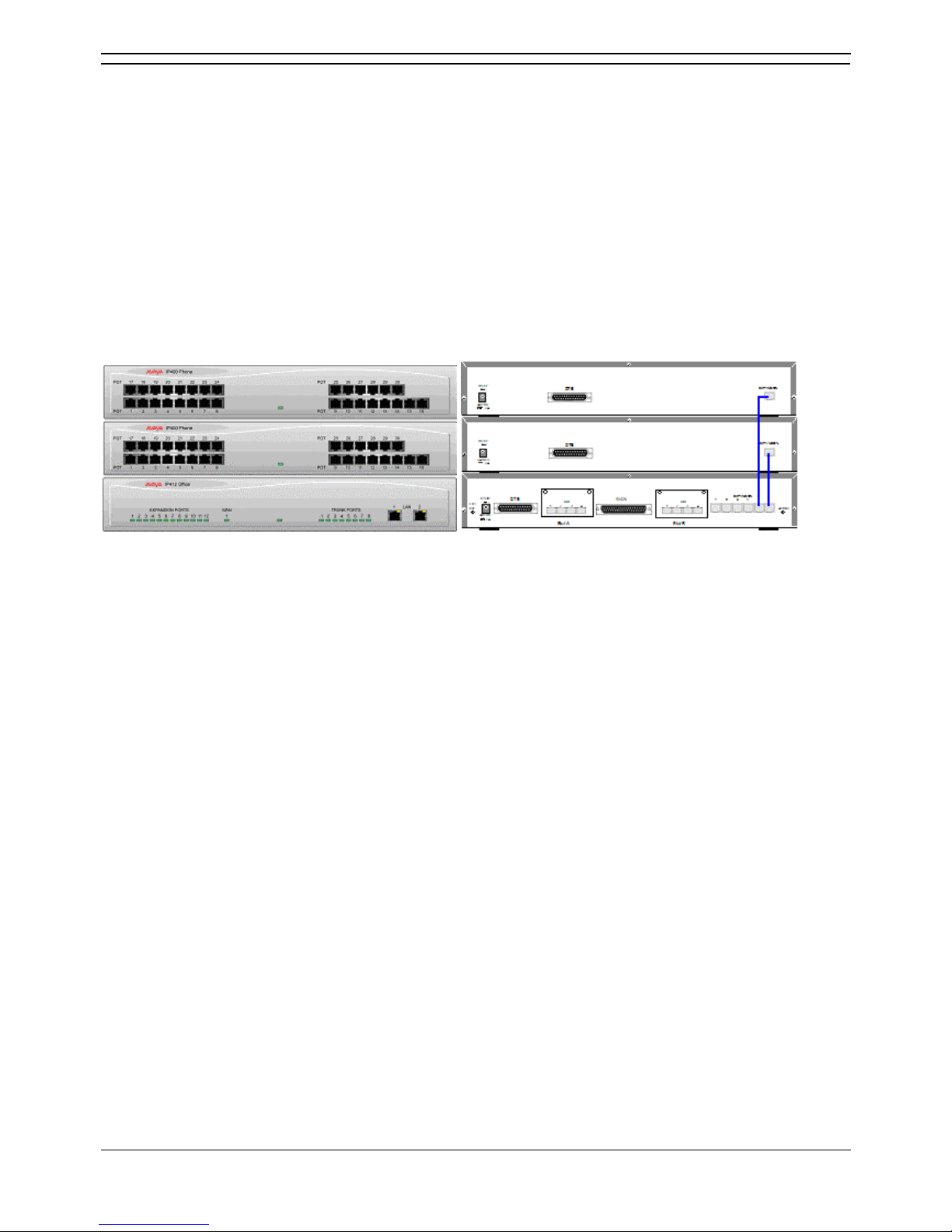
Typical Configurations
Scenario 1
A business requiring 60 analog Telephones and 8 Basic Rate ISDN lines (16 channels).
The IP406 Office BRI 16 with two IP400 Office Phone 30 modules provides the required line and
extension capacity. Through the use of PhoneManager Lite the functionality provided by the Analog
Telephones is greatly enhanced. Expansion capability for an additional 4 Modules allows the system to
be expanded to a full 180 extensions. Additional lines can be added by replacing one of the BRI
interfaces for a Primary rate.
Kit List
• IP406 Office BRI 16
• 2 x IP400 Office Phone Module 30
IP406 Office Platform
Installation Manual Page 19
IP Office 2.1 40DHB0002USCL Issue 10c (11th May 2004)
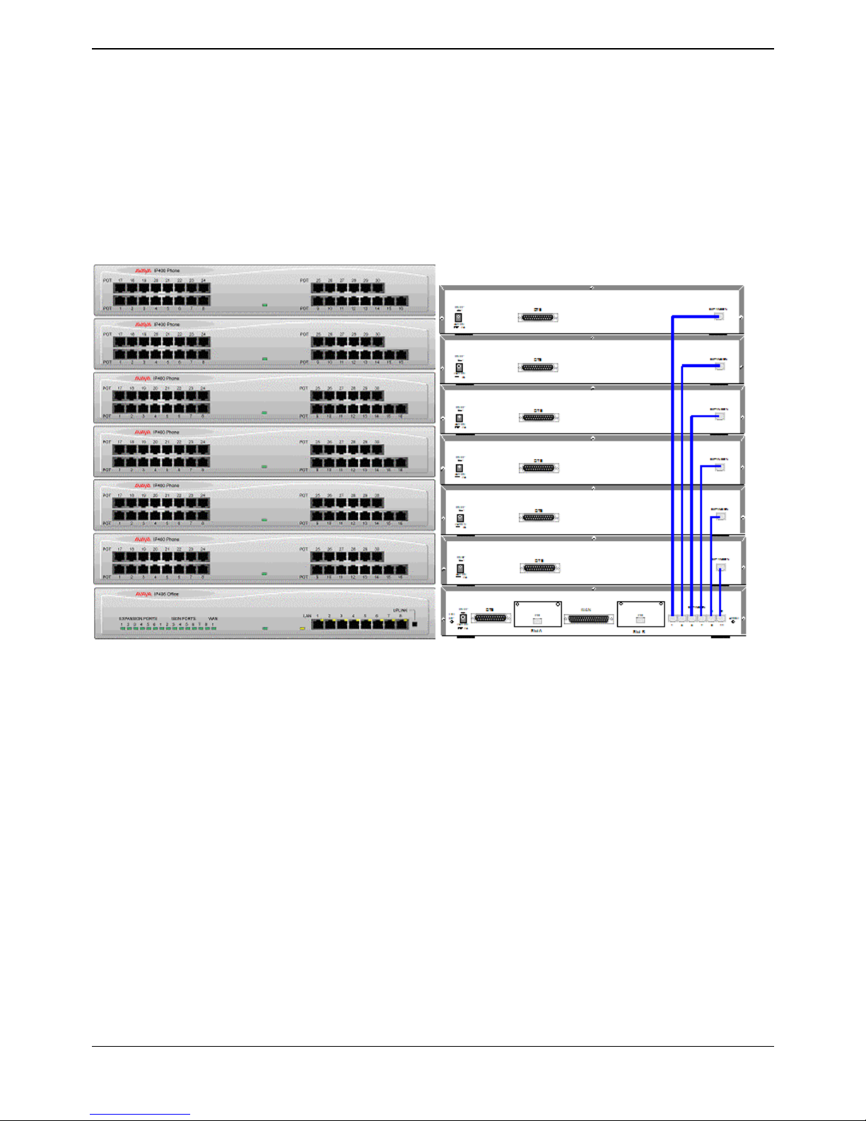
Scenario 2
A business requiring 180 analog Telephones and 60 lines.
The configuration illustrates a fully configured IP406 Office providing 180 extensions and 60 trunks.
Factory shipped with a single PRI the system is fitted with an extra trunk card in its spare slot to provide
the additional 30 lines.
Kit List
• IP406 Office PRI 30 E1 fitted with an additional IP400 IP PRI E1 trunk card
• 6 x IP400 Office Phone Module 30


Installation Manual Page 21
IP Office 2.1 40DHB0002USCL Issue 10c (11th May 2004)
IP412 Office Platform
IP412 Office
The IP412 Office base unit supports up to 360 extensions by using up to12 Expansion modules.
Connection to trunks is via a combination of any of the following integral interface modules :-
• Single or Dual PRI E1/PRIE1-R2 (30 or 60 trunks respectively).
• Single or Dual PRI T1 (24 or 48 trunks respectively - USA only).
• Quad BRI (8 trunks).
• Analog 4 (4 loop start trunks).
See IP400 Office Systems
for country specific variants.
Dual independent auto-negotiating 10/100 BaseT Ethernet ports provide segmented access (allows a
firewall break to be used) to the LAN. Where IP telephones are to be used a suitable LAN switch with
QoS capabilities, must be used.
Expansion Modules
Optional Expansion Modules allow the IP412 Office to be expanded to a maximum of 360 digital or
analog extensions. The Expansion Modules (with the exception of the WAN3 – see below) are
connected via the Expansion Port sockets that are located on the back of each unit.
Up to twelve, in any combination, of the following Expansion Modules can be supported by the IP412
Office base unit provided that the maximum number of extensions does not exceed 360.
• IP400 Digital Terminal 16/30 or Digital Station 16/30
Two variants of both (for 16 or 30 extensions) for digital telephones. Hence, twelve IP400 Digital
Terminal/Station modules can be fitted to allow a maximum of 360 digital extensions.
• IP400 Phone 8/16/30
Three variants (for 8, 16 or 30 extensions) for analog telephones. Hence, twelve IP400 Phone
modules can be fitted to allow a maximum of 360 analog extensions.
• IP400 So8
An S-bus module that provides 8 Basic rate ISDN interfaces.
• IP400 WAN3
Provides support for a further 3 digital leased line (WAN) connections. These expansion modules
are connected to the IP403 Office unit via one of the LAN Ports located on the front of each unit.
• IP400 Analog Trunk 16
Provides support for up to 16 Loop Start or Ground Start analog trunks. Two power fail sockets
are also provided.
Integral Modules (Optional)
In addition the IP412 Office can be fitted with either or both of the following optional Integral Modules:
• Voice Compression Module (VCM)
Provides VoIP applications including trunking and support for IP telephones. Available in 5, 10,
20 and 30 channel variants. The IP412 Office can have two VCMs (of any type).
• Dual Modem Module
Allows termination of two simultaneous analog modem calls at speeds up to and including
56kbps (V.90).
IP Office Installation
Installation Manual Page 22
IP Office 2.1 40DHB0002USCL Issue 10c (11th May 2004)
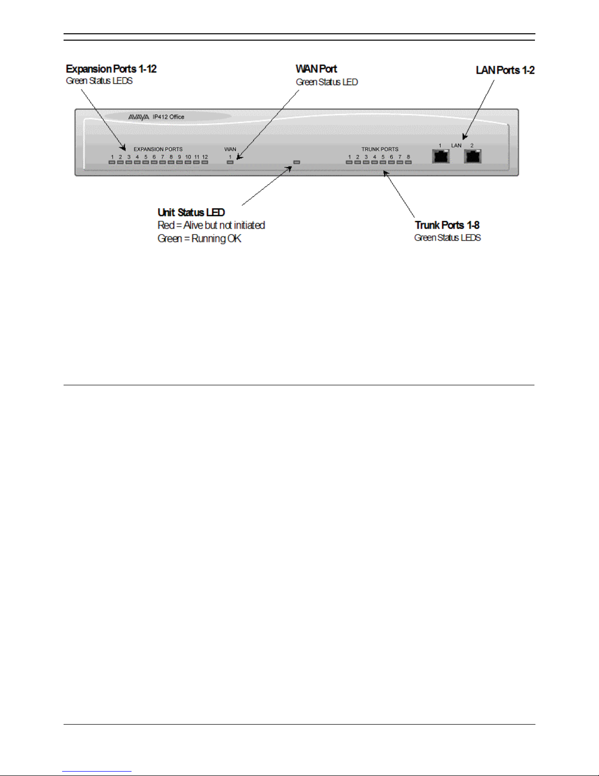
IP412 Office - Front View
• LAN Ports
The segmented dual independent auto-negotiating 10/100 BaseT Ethernet ports are used for PC
and server connectivity. They can also be used to connect to the optional IP400 WAN3
Expansion Module and IP telephones.
Information relating to incoming and outgoing telephone calls can be forwarded to PC based applications
via these ports. These segmented Ethernet ports support separate IP and MAC addresses and hence a
Firewall break may be implemented. They also provide access to the router functionality/configuration of
the IP412 Office platform for both data and Voice over IP (VoIP) calls. Where IP telephony is required, a
suitable switch LAN switch with QoS capabilities.
Cables
IP412 Office DT PRI 30 E1 & DS PRI 24 T1 are supplied with one red CAT5E cable. IP412 Office DT
PRI60 E1 & PRI48 T1 are supplied with two red CAT5E cables.
IP412 Office Platform
Installation Manual Page 23
IP Office 2.1 40DHB0002USCL Issue 10c (11th May 2004)
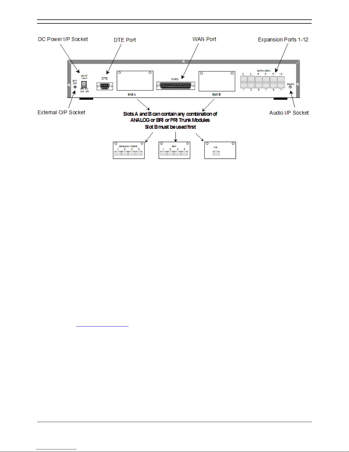
IP412 Office - Rear View
• External O/P Socket
Two relay ports that allow externally powered circuits to be controlled via a single 3.5mm stereo
jack socket.
• DC Power I/P Socket
Socket for the external 24V DC unregulated power supply (supplied with kit).
• DTE Port
A 9-way D-type socket. Used for connection to PCs, servers and EFTPOS terminals.
• BRI/PRI/ALOG Ports
The trunk interface modules are fitted into either Slots A or B as follows:
• Slot A
• Quad Analog: 4 trunks
• Quad BRI: 8 trunks
• Single or Dual PRI E1/E1-R2: 30 or 60 trunks respectively
• Single or Dual PRI T1: 24B/ 23B+1D or 48B/46B+2D trunks respectively.
• Slot B
• Single or Dual PRI E1/E1-R2: 30 or 60 trunks respectively
• Single or Dual PRI T1: 24B/ 23B+1D or 48B/46B+2D trunks respectively.
• PRI T1trunks support both ISDN and Analog emulation. The default setting is 23B+1D
(46B+2D) and is switchable in the installation software to become a 24B (48B) trunk. See
Integral Module Kits
for country specific variants.
• WAN Port
This port supports a single synchronous data connection, which can be X.21, V.35 or V.24. The
selection of the required interface is automatically determined from the pin-out of the cable
plugged into the WAN port. This cable must be connected before power is applied for auto
detection to work. Connection to a Digital Leased Circuit is made by connecting the WAN port on
the rear of the unit to the supplied Network Terminating Unit (NTU) via the appropriate X.21/V.35
/V.24 cable. This interface is identical to those on the WAN3 Expansion Module.
• Expansion Ports 1-12
Used to provide access to either optional Expansion Modules which allow the IP412 Office to be
expanded to 256 extensions or additional WAN interfaces.
• Audio I/P Socket
A single 3.5mm stereo or mono jack socket that enables input from an external 'Music-on-Hold'
source.
IP Office Installation
Installation Manual Page 24
IP Office 2.1 40DHB0002USCL Issue 10c (11th May 2004)
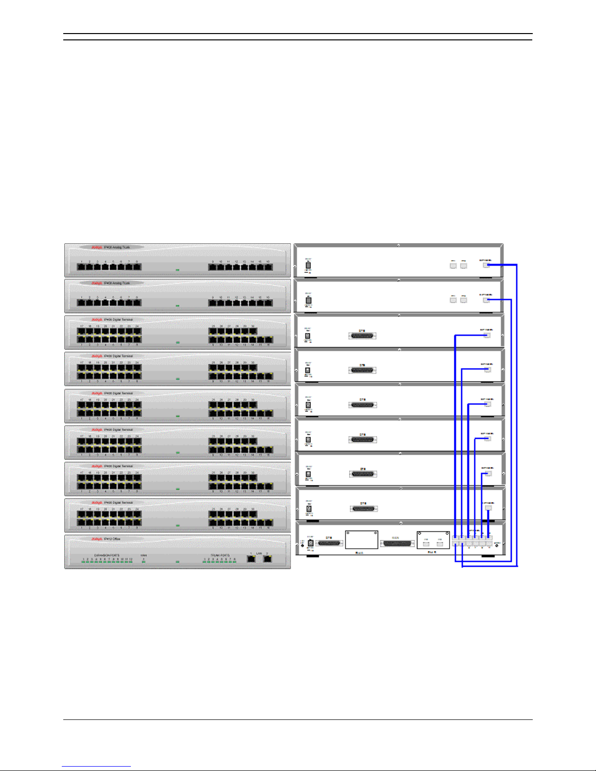
Scenario 1
A business requiring 180 Display Telephones and 96 Digital lines with 20 Analog lines for fall back
purposes in the event of the T1 service failing.
The configuration illustrates a fully configured IP412 Office providing 180 extensions and 96 digital
trunks (4 x T1) and two IP400 Office Analog Trunk 16 modules offering capacity of up to 32 analog trunk
lines. Factory shipped with a single Dual PRI T1 interface, the system is fitted with an extra trunk card in
its spare slot to provide the additional 48 lines.
Kit List
• IP412 Office PRI 48 T1
• 6 X IP400 Office Digital Station 30 Module
• 2 x IP400 Office Analog Trunk 16
• 180 x Avaya 6412 Digital Terminals
 Loading...