


LUPCMALL

PCM Paging Control System
Installation and Use Manual
© 2004 Bogen Communications, Inc.
All rights reserved. 54-2011-01D 1011
Model: LUPCMALL
PEC Code: 5323-106
COM Code: 408186013
Select Code: 701-000-109
Issue 4, November 2010

Notice
Every effort was made to ensure that the information in this
guide was complete and accurate at the time of printing.
However, information is subject to change.
FCC Statement (Part 15) - Radio Frequency
Interference
The PCM Paging Control System generates and uses radio
frequency energy and, if not installed and used in strict
accordance with the manufacturer's instructions, may cause
interference to radio and television reception. This equipment
is component registered with the Federal Communications
Commission (FCC) in accordance with Part 15 of its rules and
Canadian D.O.C. regulations. However, there is no guarantee
that interference will not occur in a particular installation. If this
equipment does cause interference to radio or television
reception, which can be determined by turning the PCM Paging
Control System unit off and on, the user is encouraged to try
to correct the interference by one or more of the following
measures:
- Reorient the radio or TV receiving antenna.
- Relocate the PCM Paging Control System unit with respect to
the radio or TV receiver or vice-versa.
- Plug the PCM Paging Control System unit into a different
outlet so that it and the radio or TV receiver are on different
branch circuits.
If necessary, the user should consult the dealer or an
experienced radio/television technician for additional
suggestions. The user may find the following booklet, "How To
Identify and Resolve Radio-TV Interference Problems," helpful. This
booklet was prepared by the Federal Communications
Commission (FCC) and is available from the U.S. Government
Printing Office, Washington, DC 20402. Stock order No. 004000-00345-4.
Federal Communications Commission (FCC)
Statement (Part 68)
This equipment is component registered with the Federal
Communications Commission (FCC) in accordance with Part
68 of its rules. In compliance with the rules, be advised of the
following:
Registered equipment may not be used with Coin Telephone
Lines. Equipment may be used with Party Lines in areas where
state tariffs permit such connections and when equipment is
adaptable for such service.
This equipment is registered as follows:
Registration Number - CD2KOR-74854-PA-N
Ringer Equivalence - 1.0B
If trouble is experienced, the equipment should be disconnected
from the interface to determine if this equipment, or the
telephone line, is the trouble source. If the equipment is
determined to be malfunctioning, it should not be reconnected
until repairs are effected.
Repairs to this equipment, other than routine repairs, can be
made only by the manufacturer or its authorized agents.
If the equipment causes harm to the telephone network, the
local telephone company may temporarily discontinue your
service and, if possible, notify you in advance. If advance notice
is not practical, you will be notified as soon as possible. You will
be given the opportunity to correct the problem and informed
of your right to file a complaint with the FCC.
The local telephone company may make changes in its facilities,
operations, or procedures that could affect the proper
functioning of your equipment. If they do, you will be given
adequate notice in writing to allow you an opportunity to
maintain uninterrupted telephone service.
Important Safety Information
Always follow these basic safety precautions when installing and
using the system:
1. Read and understand all instructions.
2. Follow all warnings and instructions marked on the
product.
3. DO NOT block or cover the ventilation slots and
openings. They prevent the product from overheating. DO
NOT place the product in a separate enclosure or cabinet,
unless proper ventilation is provided.
4. Never spill liquid on the product or drop objects into the
ventilation slots and openings. Doing so may result in
serious damage to the components.
5. Repair or service must be performed by a factory
authorized repair facility.
6. The product is provided with a UL-CSA approved, 3-wire
ground type plug. This is a safety feature. DO NOT defeat
the safety purpose of the grounding type plug. DO NOT
staple or otherwise attach the AC power supply cord to
building surfaces.
7. DO NOT use the product near water or in a wet or damp
place (such as a wet basement).
8. DO NOT use extension cords. The product must be
installed within 6 feet of a grounded outlet receptacle.
9. DO NOT install telephone wiring during a lightning storm.
10. DO NOT install telephone jacks in a wet location unless
the jack is specifically designed for wet locations.
11 Never touch uninsulated wires or terminals, unless the line
has been disconnected at the paging or controller interface.
12. Use caution when installing or modifying paging or control
lines.
Support Information
Paging systems integrated with small phone systems such as
Merlin Legend and Partner are supported by the National
Service Assistance Center (NSAC). The main number for the
NSAC is 800-628-2888. Paging systems integrated with large
switches such as the DEFINITY G3 are supported by the
Technical Service Center (TSC). The main number for the TSC
is 800-242-2121.
© 2004 Bogen Communications, Inc.
All Rights Reserved.

[3]
Contents
1. Introduction..........................................................................................................................5
1.1. Voice Channel ........................................................................................................5
1.2. Background Music ..................................................................................................6
1.3. Signaling Channel ..................................................................................................6
1.4. Other Features ........................................................................................................6
2. Before You Start ..................................................................................................................7
2.1. Select Options..........................................................................................................7
2.2. Package Contents ....................................................................................................7
3. Installation............................................................................................................................9
3.1. Adding PCMZPM Modules ....................................................................................9
3.2. Mounting the PCM System ....................................................................................9
3.2.1. Wall Mounting ........................................................................................................9
3.2.2. Rack Mounting ........................................................................................................9
4. LUPCMALL Feature Callouts ..........................................................................................11
5. System Wiring Connections................................................................................................13
5.1. Telephone System Connections ..............................................................................13
5.2. PBX Loop Start Trunk Port ....................................................................................13
5.3. PBX Ground Start Trunk Port ................................................................................14
5.4. PBX Page Port ........................................................................................................15
5.5. PBX Analog Station Port ........................................................................................15
5.6. Night Ringer ............................................................................................................16
5.7. Override Input ........................................................................................................17
6. Paging Amplifier Connections............................................................................................19
7. Background Music ..............................................................................................................21
7.1. Helpful Hints When Connecting Background Music to the
Paging Control System............................................................................................21
7.2. Background Music Continuously Supplied To All Zones Not Being Paged ........23
7.3. Background Music Supplied By Same Amplifier That Supplies
Paging, Music Input Available On Amplifier ........................................................23
7.4. Background Music Supplied by Same Amplifier Supplying Paging,
No Dedicated Music Input Available On Amplifier ..............................................23
7.5. Background Music Or Different Background Music Supplied
To A Select Group Of Zones ..................................................................................23
7.5.1. Zone Modules Working With 70V Speakers..........................................................23
7.5.2. Zone Modules Working With Self-Amplified Speakers ........................................23
7.6. Inhibiting Background Music In Select Zones ......................................................23
8. Zone Speaker Wiring and Setup ........................................................................................29
8.1. Wiring to 70V speakers ..........................................................................................29
8.2. Wiring to Self-Amplified Speaker or Dedicated Amplifier....................................29
8.3. Setting a Zone for Talk Back Operation ................................................................29

[4]
9. Optional Wiring ..................................................................................................................33
9.1. CPU to Emergency Signaling ................................................................................33
9.2. CPU to Re-Synch (Master Clock) ..........................................................................33
9.3. Relay Drivers ..........................................................................................................33
10. Power-Up of PCM and Associated Equipment ................................................................35
10.1. Power-Up Sequence ................................................................................................35
10.2. Priority Order ..........................................................................................................35
11. System Programming ..........................................................................................................37
11.1. Programming Paging Zone Groups ........................................................................38
11.1.1. To Erase A Zone Paging or Signaling Group ........................................................38
11.2. Programming Signaling Zone Groups ....................................................................38
11.3. Interface Default Timer ..........................................................................................38
11.4. Interface VOX Timer ..............................................................................................38
11.5. Dialing Timeout ......................................................................................................38
11.6. Single Amp BGM....................................................................................................39
11.7. Programming Real Time Clock ..............................................................................39
11.7.1. Clock Synchronization ............................................................................................39
11.8. Time-Triggered Events............................................................................................39
11.9. Setup Tone ..............................................................................................................39
11.10. Reset Default Values ..............................................................................................39
11.11. Relay Contacts ........................................................................................................39
12. Feature Codes and Defaults................................................................................................41
13. Paging: How To Use The PCM ..........................................................................................45
13.1. Paging Zones ..........................................................................................................45
13.2. How To Page Zones ................................................................................................45
13.3. How To Make An All-Call Page ............................................................................45
13.4. How To Page A Zone Group ..................................................................................45
13.5. How To Make A Code Call ....................................................................................46
13.6. How To Make A Pattern Code Call........................................................................46
13.7. How To Make An Echo Code Call ........................................................................47
14. Testing and Troubleshooting..............................................................................................49
Appendix A: Applications............................................................................................................53
Appendix B: Tones ......................................................................................................................59
Appendix C: Glossary of Programmable Features ..................................................................61
Appendix D: Configuration Forms ............................................................................................63
[5]
1. Introduction
PCM
TIM
PCM
CPU
PCM
TBM
PCM
ZPM
Figure 1-1: LUPCMALL Paging System Control Assembly
The PCM Paging Control System (see Figure 1-1) is an expandable zone paging and signaling system. The LUPCMALL
consists of 4 pre-assembled modules: PCMTIM, PCMCPU, PCMTBM, and a Zone Paging Module (PCMZPM). To this, you
can add up to two additional Zone Paging Modules (Model: LUPCMZONE, Pec Code 5323-108, Com Code 408186039) to
increase system zone paging capacity to 9 zones.
If more than 9 zones are required, expansion assemblies (Model: LUPCMADD, Pec Code 5323-107, Com Code 408186021)
can be added up to a total capacity of 99 zones in 3 zone increments. Expansion assemblies include a PCMCPU and a
PCMZPM.
The Paging Control System provides the following features and functions:
1.1. Voice Channel
• Zone Paging & sub zone group paging (up to 32 zone groups, each with up to 99 zones)
• Override paging (using loop start or contact closure)
• Talk Back paging (centrally-amplified zones only)
• Talk/Talk Back selection per zone
• High/Low-powered central paging
• High/Low-powered distributed paging
• Privacy Beep on talk back zones
• Pre-Announce Tone

[6]
1.2. Background Music
• High/Low-Powered distributed (buffered for up to 50 amplified speakers)
• High/Low-Powered, using dedicated BGM amplifier
• High/Low-Powered using a single paging/BGM amplifier
• BGM Disable to individual zones
• Local BGM input on each individual zone module
1.3. Signaling Channel
• Night Ringer (90V or contact closure activation)
• Code Calling (2 types - echo & pattern)
• Emergency/Shift Change Tone (tone and duration selectable)
• Specialized modules provide Time-Triggered signaling
1.4. Other Features
• DTMF setting of all operating parameters
• Run/Program switch
• External C-form contacts
• Relay Driver output per zone
• Non-volatile memory for setup data (no backup battery required)
• Setup Tone to assist in volume setting, etc.
• Synchronization to external master clocks

[7]
2. Before You Start
2.1. Select Options
Before setting up your system, use the checklist below to assist you in setting up and programming the PCM Paging
Control System.
____ Type of Telephone Interface (loop start, ground start, page port, station port)
(see System Wiring Connections, Section 5)
____ Total Number of Paging Zones (additional Zone Paging Modules or LUPCMADD Paging Control System
Assemblies may be required) (see Installation, Section 3)
____ Zone Groups (see Section 11.1)
____ Time-Triggered Signaling (see Sections 11.2 and 11.8):
____ Signaling Zone Groups (see Sections 11.2 and 11.8)
____ Clock Synchronization (see Section 11.7.1)
____ All-Call Capability (see Section 11.1)
____ Code Calling Capability (see Section 11.2)
____ Background Music (see Section 7):
____ Continuous in Zones Not Being Paged (see Section 7.2)
____ Cease in All Zones During Page (see Sections 7.3 and 7.4)
____ Inhibited in Some Zones (see Section 7.6)
____ Different in Some Zones (see Section 7.5)
____ Night Ring Capability (see Section 5.6)
____ Override Capability (see Section 5.7):
____ From Telephone/Loop Start Trunk (see Section 5.2)
____ From External Audio Equipment (see Appendix A)
2.2. Package Contents
• 4 pre-assembled modules - PCMTIM, PCMCPU, PCMTBM, and PCMZPM
• Power Supply
• Rack Mount brackets (2)
• Installation and Use Manual
• Screws
[8]
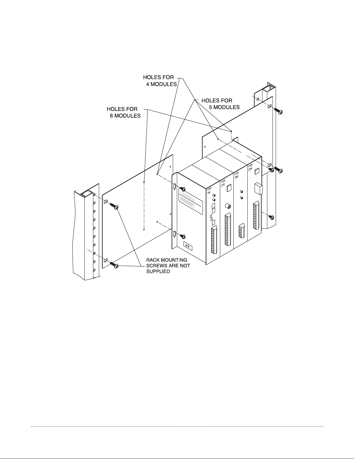
Figure 3-1: Rack Mounting the LUPCMALL Paging Control System

[9]
3.1. Adding PCMZPM Modules
The LUPCMALL is pre-assembled to accommodate 3 zones of paging. If your installation requires 4 to 9 zones, you can add
one or two Zone Paging Modules (PCMZPM). A total of 3 PCMZPM modules (9 zones total) can be used on a LUPCMALL
assembly. If your installation requires more than 9 zones, you will need one or more LUPCMADD units to allow system
expansion beyond 9 zones. Install the extra PCMZPM modules before mounting and wiring the PCM System assemblies.
(Refer to the LUPCMZONE installation manual.)
NOTE:
LUPCMADD Paging Control System Expansion Assemblies and Zone Paging Modules can only be added when the
previous assembly contains 3 PCMZPM modules; otherwise, the system will not operate.
3.2. Mounting the PCM System
The Paging Control System Assemblies can be either wall- or rack-mounted.
3.2.1. Wall Mounting
1. After assembling the unit (if necessary) hold the unit level against the surface to which it will be mounted.
2. Mark where the mounting screws should be positioned.
3. Set the assembly aside and install the screws leaving about ¼" of the screw sticking out of the surface.
4. Slip the assembly over these screws and tighten them snuggly.
3.2.2. Rack Mounting
1. Position the left side of the completed PCM assembly (any additional PCMZPM modules should have already been
added) over one of the rack mounting adapters. Refer to Figure 3-1 and use the correct holes for the number of modules
in the assembly (4, 5, or 6 as shown).
2. Secure the left side of the PCM system to the rack adapter using two of the truss head sheet metal screws.
3. Secure the right side of the PCM system to the other rack adapter using the holes for the number of modules in the
assembly and the remaining 2 truss head sheet metal screws.
4. Secure the assembly to a 19" rack (rack screws not supplied).
3. Installation
[10]
PCM
Figure 4-1: LUPCMALL Feature Callouts
TIM
PCM
CPU
PCM
TBM
PCM
ZPM

[11]
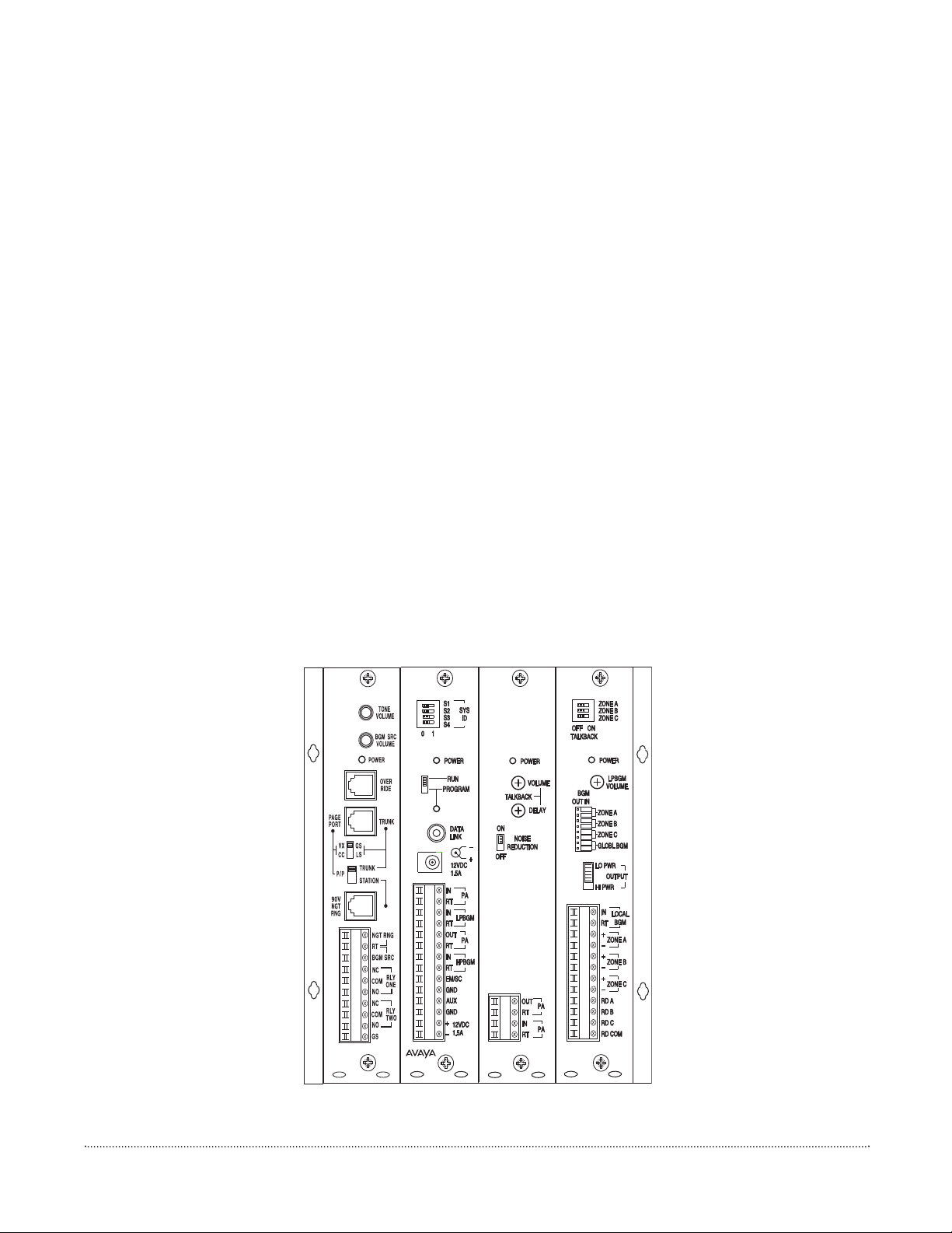
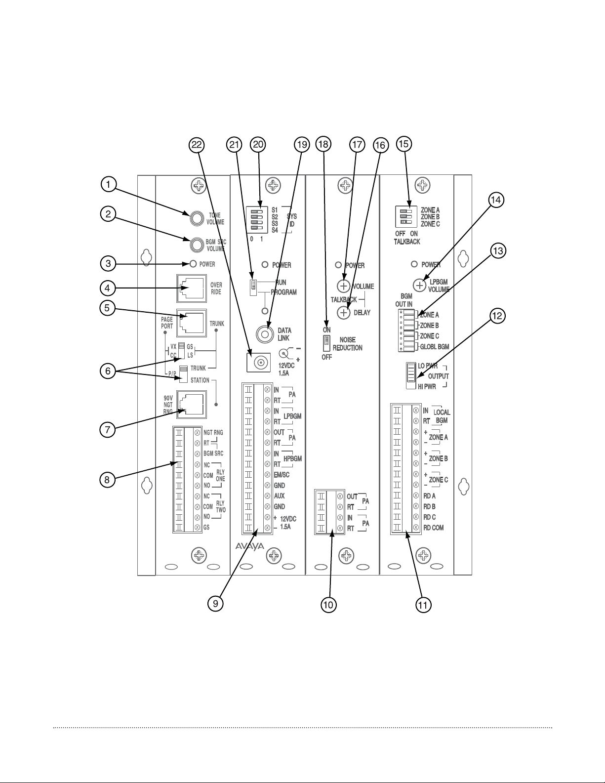
Descriptions and Locations
Refer to Figure 4-1.
1. TONE VOLUME - Controls the level of all tones produced by the PCM system.
2. BGM SRC VOLUME - Sets background music level for one mode of operation. Used only when an amplifier without
a music input is used as the paging amplifier (see Section 7).
3. POWER - Indicates that power has been supplied to the module. One exists on each module.
4. OVERRIDE - Secondary paging input with higher priority than TEL LINE input. Connects to either loop start trunk or
dry audio signal with contact closure (see Section 5.7).
5. PAGE PORT/TRUNK - Interface to telephone switch (see Section 5).
6. TEL INT SEL Switches - Sets telephone interface type for the LOOP START/GROUND START, TRUNK/PAGE
PORT and STATION jacks on the PCMTIM module (see Section 5).
7. 90V NIGHT RING/STATION - This RJ11 jack provides connections to the internal Night Ringer for both 90V analog
ring and the Station type interface.
8. PCMTIM Terminal Strip - Provides connections for Night Ring contact closure activation, background music source
(one mode of operation only) (see Section 7), ground start interface ground (see Section 5.3), and two sets of contact
closures that change state whenever a paging zone is active (see Section 11.11).
9. PCMCPU Terminal Strip - Provides connections to background music audio signals (see Section 7), system expansion
signals (see LUPCMADD manual), EM/SC signal trigger (see Section 9.1), clock resynchronization (see Section 9.2),
and auxiliary power supply input.
10. PCMTBM Terminal Strip - Provides connection to main paging amplifier (see Section 6).
11. PCMZPM Terminal Strip - Provides connections to paging speakers (see Section 8), separate local background music
source (see Section 7), and relay driver outputs (see Section 9.3).
12. OUTPUT Switch - Switch setting determines if the PCMZPM module will be compatible with 70V (Hi) speaker systems
or self-amplified speakers (Lo). Locking plate guards against accidental changes in setting.
13. BGM Jumper Field - Jumpers control whether background music is inhibited to a specific zone or all zones
(see Section 7).
14. LPBGM VOLUME - Controls the level of background music in zones using self-amplified speakers. Works only with
system-wide BGM, no effect if local BGM source is used.
15. TALK BACK Switch Bank - Determines if a 70V speaker zone will operate as a two-way hands-free talk back zone or
as a one-way paging zone (see Section 8.3).
16. TALK BACK DELAY - Controls the amount of delay, after speaking stops, before the system switches to the listen
mode during talk back operation (see Section 8.3).
4. LUPCMALL Feature Callouts

[12]
17. TALK BACK VOLUME - Controls the audio level of the talk back signal (see Section 8.3).
18. NOISE REDUCTION - Enables or disables noise reduction during talk back listening. Mutes listen signal when audio
activity is low (see Section 8.3).
19. DATA LINK - Data com port used to control other module assemblies in the PCM paging system. Uses simple RCA
cables to interconnect units (see LUPCMADD manual).
20. SYS ID - Switch bank used to set unique address of the PCMCPU module when other LUPCMADD assemblies are used
in the paging system.
21. RUN/PROGRAM Switch - Switch must be set to the PROGRAM position before any system programming can be done.
Return to RUN position for normal system operation. Locking plate ensures that switch will not be accidentally set to
program mode. Switch only needs to be changed on the LUPCMALL main assembly. LUPCMADD assemblies always
stay in RUN mode (see Section 8.1).
22. 12V DC Power Jack - PCM system power supply connects to this jack.
[13]
5.1. Telephone System Connections
The PCMTIM module is the telephone interface module for the PCM Paging Control System. The PCMTIM provides the
telephone interface (including talk battery), night ringer input, emergency override input, and auxiliary relay contacts for the
system. The module is also responsible for all tone signaling features.
The PCM connects to virtually any telephone system: PBX station lines and CO lines, PBX loop start trunk ports, PBX ground
start trunk ports, and page ports (using contact closure).
Interface installation consists of setting Slide switches and connecting with modular (RJ11) telephone plugs.
Refer to the appropriate procedure in this section to connect the PCM System to the telephone system.
Note: In all cases, make sure that power is off to the PCM and any amplifiers being connected to it before performing the
installation.
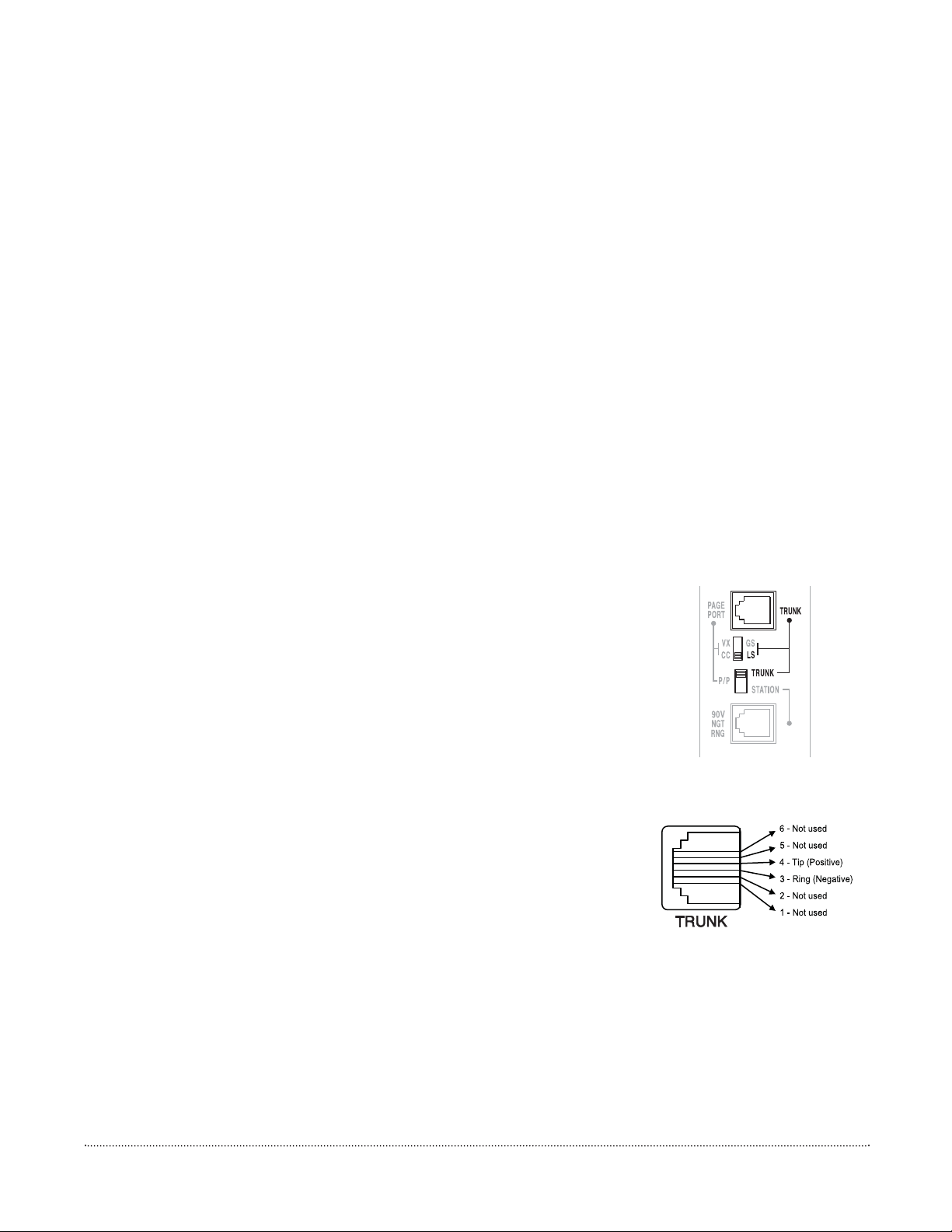
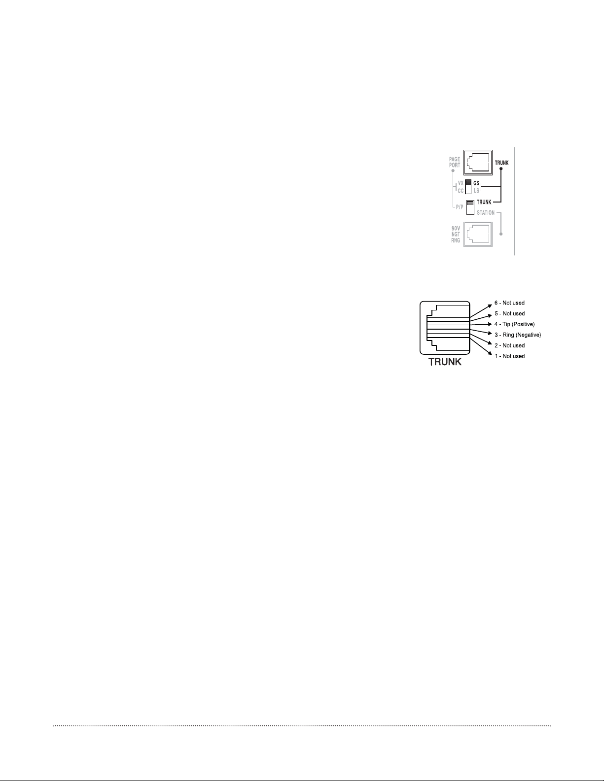
5.2. PBX Loop Start Trunk Port
In this configuration, the PCM unit supplies a 48V talk battery and loop current detection from pins 3 & 4 of the TRUNK
jack on the PCMTIM module to the loop start trunk in the telephone system. There are two modes of operation for loop
start trunk.
(1) When the unit detects a loop resistance between TIP and RING, it activates. When
the loop opens, the page ends. Pins 1, 2, 5 & 6 are not used in this configuration.
Note: Default and VOX timers are not used in this mode.
(2) The unit will operate as in mode one, except it will also provide a one-second hook
flash after the expiration of the VOX and/or Default timers. Operation in this mode
will enable the unit to automatically disconnect itself from the loop start trunk of
the PBX. This will prevent the paging system from being locked up indefinitely in
the event a telephone is accidentally left off hook after a page has been completed.
The feature codes are 014 to inhibit and 015 to enable this feature. The default
feature code is 014 (OFF).
1. Make sure that power is off and all connections completed before proceeding.
2. Move the Slide switches on the module to the position shown in Figure 5-1.
3. Use a modular telephone cord to connect the module to the phone system. Plug one
end of the cord into the Loop Start Trunk (using a modular jack) and the other end in
to the TRUNK jack on the module.
The center two conductors are Tip and Ring (48V DC) and have a specific polarity. If the
polarity of the trunk is opposite, you can use a reversing modular cord to make the
connection or reverse the connection through a modular block. Refer to
Figure 5-2 for more information.
IMPORTANT: The polarity of the Tip & Ring contacts of the RJ11 jack for the Trunk and Override were chosen so that
when a standard modular cord (one with the tops of both end plugs on the same side of the flat cable) is used to connect the
PCM to a modular wall block, the modular block G (Tip) terminal will be positive with respect to the R (Ring) terminal.
Because of variations in types of modular cords and when stripping a modular cord for direct connection, always check the
polarity of the center conductors or R & G terminals to determine Tip & Ring (the positive lead is Tip and the negative lead
is Ring).
5. System Wiring Connections
Figure 5-1: Loop Start
Telephone Selector Switches
Figure 5-2:
Loop Start/Ground Start RJ11
[14]
5.3. PBX Ground Start Trunk Port
In this configuration, the PCM unit supplies a 48V talk battery and loop current detection from pins 3 & 4 of the TRUNK
jack on the PCMTIM module to the ground start trunk in the telephone system. There are two modes of operation for
ground start trunk.
(1) When the ground start trunk grounds Ring, the unit responds by closing the
connection to Tip, which completes the access procedure. When the loop is opened,
the page ends. Pins 1, 2, 5 & 6 are not used in this configuration.
Note: Default and VOX timers are not used in this mode.
(2) The unit will operate as in mode one, except it will also provide a one-second hook
flash after the expiration of the VOX and/or Default timers. Operation in this mode
will enable the unit to automatically disconnect itself from the ground start trunk of
the PBX. This will prevent the paging system from being locked up indefinitely in
the event a telephone is accidentally left off hook after a page has been completed.
The feature codes are 014 to inhibit and 015 to enable this feature. The default
feature code is 014 (OFF).
1. Make sure that power is off and all connections completed before proceeding.
2. Move the SLIDE switches on the module to the position shown in Figure 5-3.
3. Use a modular telephone cord to connect the module to the phone system. Plug one
end of the cord into the Ground Start Trunk (using a modular jack) and the other end
in to the TRUNK jack on the module.
The center two conductors are Tip and Ring (48V DC) and are polarity sensitive. If the
polarity of the trunk is opposite, you can use a reversing modular cord to make the
connection or reverse the connection through a modular block. Refer to Figure 5-4 for
more information.
IMPORTANT: The polarity of the Tip & Ring contacts of the RJ11 jack for the Trunk and Override were chosen so that
when a standard modular cord (one with the tops of both end plugs on the same side of the flat cable) is used to connect the
PCM to a modular wall block, the modular block G (Tip) terminal will be positive with respect to the R (Ring) terminal.
Because of variations in types of modular cords, and when stripping a modular cord for direct connection, always check the
polarity of the center conductors or R & G terminals to determine Tip & Ring (the positive lead is Tip and the negative lead
is Ring).
4. Use 24-gauge solid wire to connect the GS terminal on the module to the PBX ground. This is typically the AC ground
for the PBX system.
IMPORTANT: It is very important that no other terminals of the PCM system connect to AC ground when using the ground
start interface. Also, the case of the PCM system cannot be connected to AC ground. If the system is not working and no PCM
terminals (except the GS terminal) are directly connected to AC ground, there may be an indirect connection. Check the
connections to any equipment with a 3-wire AC plug. Make sure that unbalanced inputs and outputs of this equipment are
isolated using a model LUWMT1A transformer (Com Code 405891680) before connecting the equipment to the PCM.
The PA OUT and HPBGM terminals on the PCM do not have to be ground-isolated.
Figure 5-3: Ground Start
Telephone Selector Switches
Figure 5-4: Loop Start
RJ11 Connections
[15]
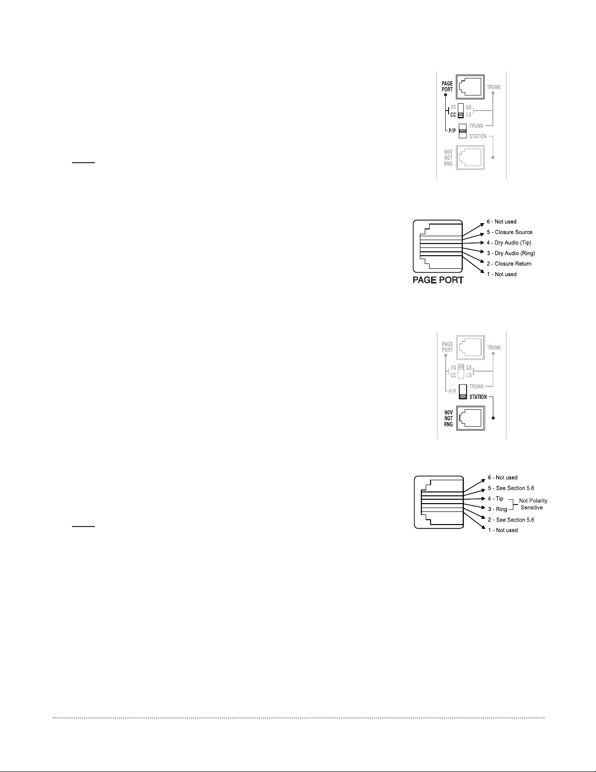
5.4. PBX Page Port
In this configuration, the unit responds to a contact shorting the closure source to its
return. When the short is removed, the page ends. Audio is provided to the system through
a separate pair of leads.
1. Make sure that power is off and all connections completed before proceeding.
Note:
Make sure that the page port produces DTMF tones. The page port must also
be bi-directional in order to use talk back.
2. Move the SLIDE switches on the module to the position shown in Figure 5-5.
3. Use a modular telephone cord to connect the module to the phone system. Plug one
end of the cord into the Page Port and the other end in to the PAGE PORT jack on
the module.
The center two conductors are used for dry audio and the connectors on either side are
connected to the page port contact closure. The maximum resistance of the page port
contact closure is 1000 ohms. Refer to Figure 5-6 for more information.
5.5. PBX Analog Station Port
In this configuration, the unit answers after the first full ring. As soon as it answers, the
default timer is started. The default timer determines the maximum length of any page.
When a paging zone is selected, the VOX timer is started (if enabled). This timer
repeatedly resets as long as audio is detected on the line. If no audio is detected within the
VOX time period, the page will end. If audio continues to be detected, the default timer
will control page length.
The unit will also respond to CPC pulses (short losses of loop current). When a CPC pulse
is detected, the unit will immediately drop the line.
1. Make sure that power is off and all connections completed before proceeding.
2. Move the TEL INT SEL (SLIDE) switches on the module to the position shown in
Figure 5-7. Use the tip of a pen or other pointed instrument to move the switches.
3. Use a modular telephone cord (minimum 2-conductor) to connect the module to the
phone system. The center two conductors are Tip and Ring and are not polarity
sensitive (see Figure 5-8). Plug one end of the cord into the PBX or CO modular jack
and the other end in to the STATION jack on the module.
4. Set Default and VOX timers. See System Programming, Section 11.
Note:
The default timeout is factory set to 30 seconds, and the VOX timeout is set to
6 seconds. If both the default and VOX timers are inhibited, the only way to
disconnect the system from the station line is the CPC pulse.
Figure 5-5: Page Port
Telephone Selector Switches
Figure 5-6: Page Port
RJ11 Connections
Figure 5-7: Station Telephone
Selector Switches
STATION
Figure 5-8: Station RJ11
Connections
STATION
[16]
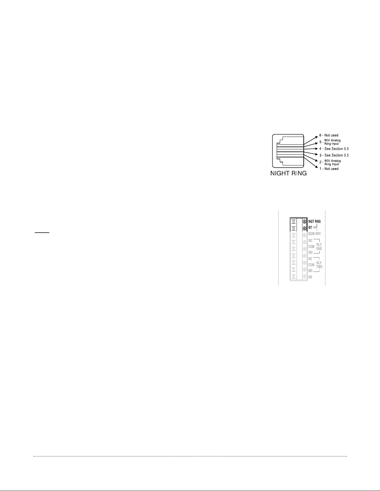
5.6. Night Ringer
The PCM Night Ringer signaling feature is designed to alert personnel to incoming calls after normal business hours. The
feature can be activated either by a 90V ring signal or by a contact closure. In the factory default configuration, the night ringer
sounds over all zones, however, a zone group can be programmed which will sound the night ringer only over a user-selected
group of zones.
The night ringer normally sounds a simulated ring tone. The ringer can be programmed to sound a chime tone or a tone
provided by a user-supplied external tone generator (see page 35).
Follow the instructions below for night ringer connections. Refer to the System Programming, Section 11, to set up a night
ringer zone group or to change to ringer tone.
To physically connect the Night Ringer:
1. Make sure that the power is OFF.
2A. For 90V Night Ring (RJ11) Jack Connection
Plug a modular cord into the 90V NGT RNG (RJ11) jack. The center conductors are
used for Station Access. The flanking conductors are for the 90V Night Ring Signal.
2B. For Contact Closure Connection
Screw terminal connections are provided for Night Ring Contact Closure
activation.
Maximum contact resistance for contact closure activation is 1000 ohms.
NGT RNG is the contact closure source (+5V).
RT is the contact closure return (GND).
Note: The Night Ring feature has priority over background music only. There is a
5 second delay after the night ring stops before background music is restored (bridges
inter-ring pause).
3. Reconnect power.
Figure 5-9: 90V Night Ring
RJ11 Connections
Figure 5-10: Night Ring
Contact Closure Connections
[17]
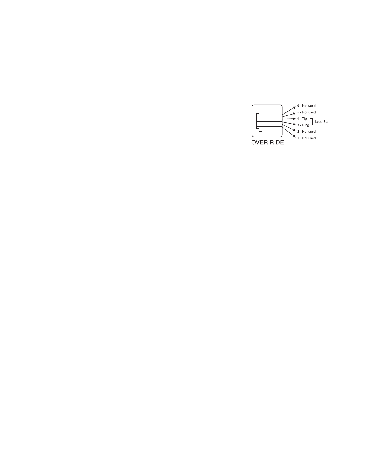
5.7. Override Input
The Override is a non-programmable feature that lets the caller take priority over all paging functions and make a systemwide page to all speakers. The feature can be activated using a loop start trunk or dedicated telephone. Provisions are also
included to interface with other signaling equipment.
The Override feature includes a quad beep pre-announce tone that can be enabled or inhibited. (The default is inhibited). See
System Programming, Section 11 to enable the tone.
1. Make sure that power is off and all connections completed before proceeding.
2. Plug modular cord into OVERRIDE (RJ-11) jack.
The center two conductors interface directly to a Loop Start Trunk or dedicated phone (see
Figure 5-10). When the trunk becomes active, the PCM goes into Override mode.
Also, see Connecting to an External Audio Source, page 53.
Figure 5-10: Override Loop Start
RJ11 Connections
[18]
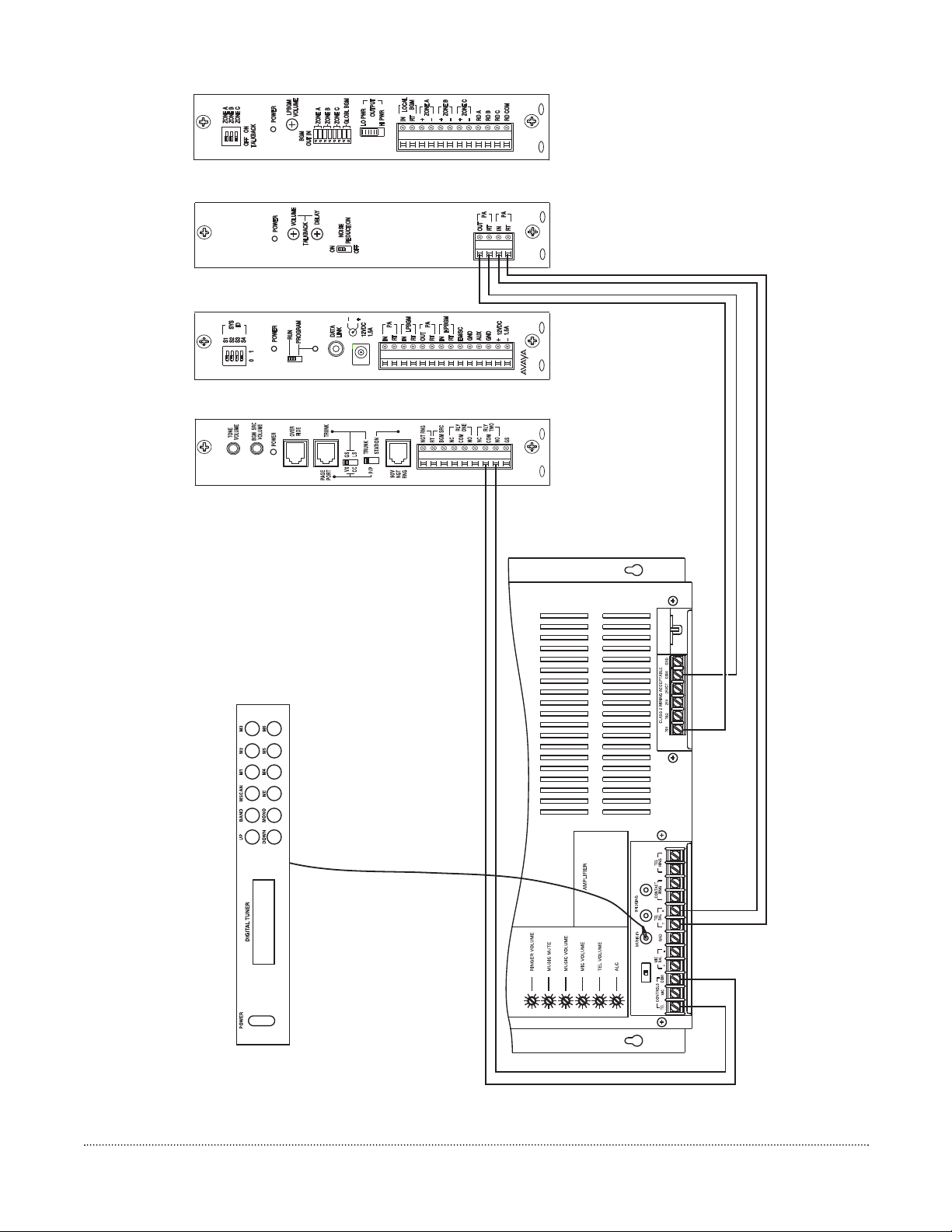
PCM
Figure 6-1: Connecting to a Telephone Paging Amplifier
PCM
PCM
PCM
ZPM
TBM
CPU
TIM

[19]
6. Paging Amplifier Connections
The paging amplifier audio connections are made to the PCMTBM module terminal strip. If the amplifier has a paging control
input, this is connected to the RLY TWO terminals on the PCMTIM module (see Figure 6-1). The paging amplifier must have
a balanced 600-ohm input. The amplifier should be located close to the PCM system to keep cable lengths reasonably short.
NOTE: To make all audio connections, use 22 AWG shielded, twisted pair on all wire runs. Com Code: 401882956, PEC
Code: 2734-SPK.
CAUTION: Make sure the amplifier is turned off or unplugged before wiring.
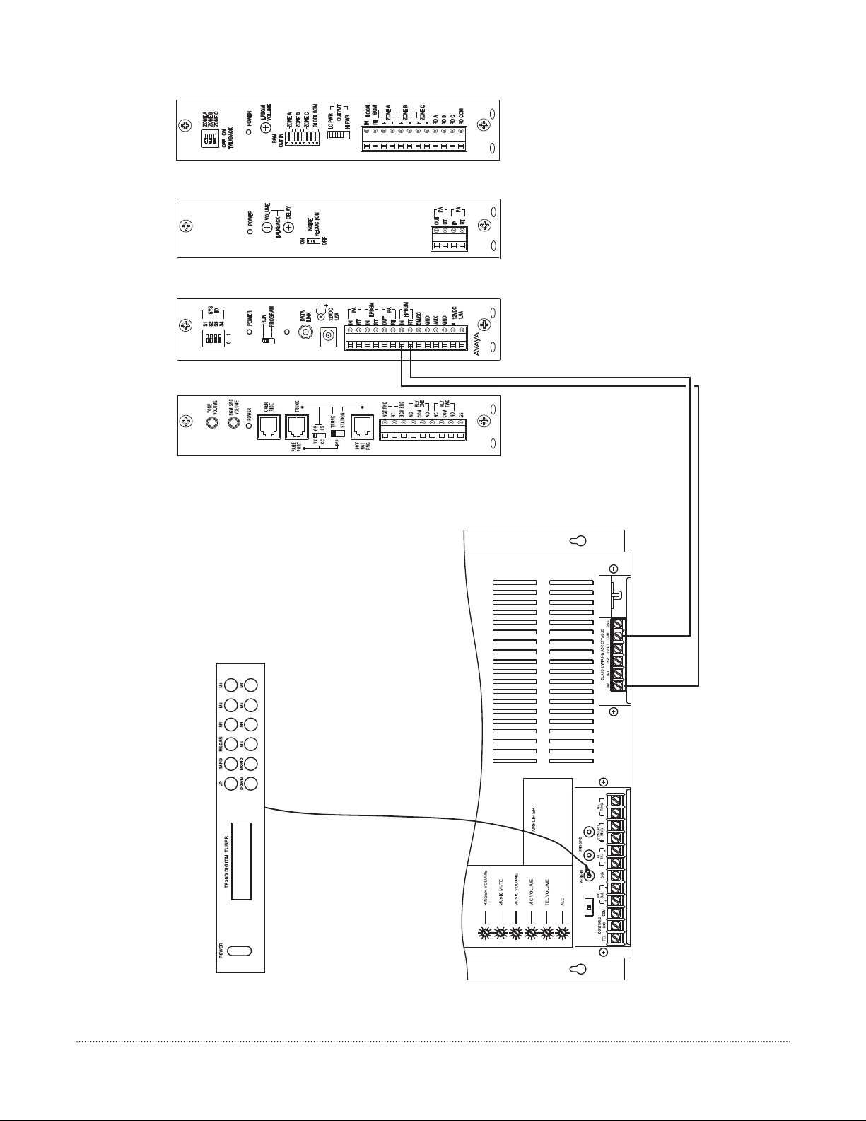
Figure 7-1: Background music continuously supplied to all zones not being paged for 70V zone speakers.
PCM
[20]
PCM
PCM
PCM
ZPM
TBM
CPU
TIM

The PCM system is very flexible in how it can provide background music throughout the system:
• Background music can be continuously supplied to all zones not being paged. (Requires two amplifiers of the same power
rating.)
• Background music can be supplied by the same amplifier that is supplying paging. (Music input is available on amplifier.)
• Background music can be supplied by same amplifier that is supplying paging. (No dedicated music input available on
amplifier.)
• Background music or different background music can be supplied to a select group of zones.
• Background music can be supplied to self-amplified (LO-PWR) zones.
• Background music can be inhibited in select groups.
The BGM SRC terminals are used to control background music operations when using a single power amplifier that does not
provide a separate music input. This feature is only used when a single amplifier will be used for both background music and
paging (background music is lost in all zones when a page is made).
NOTE
: This input and its associated control is not used when using amplifiers with separate music inputs and paging control
terminals because background music is supplied directly to the amplifier.
7.1. Helpful Hints When Connecting Background Music to the Paging Control System
1. When using the BGM SRC (background music source) input on the PCMTIM as input for background music, the music
is muted to all speakers when any zone is selected. The source input signal is line level.
2. When the HPBGM (high-powered background music) input on the PCMCPU is used, music is muted only in the zone
selected. The source input has to be an amplified signal.
3. When the LPBGM (low-powered background music) input on the PCMCPU is used as an input for background music,
music is muted only to the zone selected. In this application, either amplified speakers or an amplifier per zone is used.
PCMZPM output power switch is set to LO-PWR. The input background music is line level.
4. When the Local BGM input on the PCMZPM is selected as input for background music, music is muted only to the zone
selected. An amplified signal is required at this input if using 70V speakers.
NOTE:
When you want to mute the background music only to the zone in which you are paging, refer to 2, 3 or 4 above.
[21]
7. Background Music
 Loading...