


 Loading...
Installing and Configuring the
Avaya S8500 Media Server
Release 4.0
03-300143
Release 4.0
February 2007 Issue 5
© 2007 Avaya Inc.
All Rights Reserved.
Notice
While reasonable efforts were made to ensure that the information in this document was complete and accurate at the time of printing, Avaya Inc. can assume no liability for any errors. Changes and corrections to the information in this document may be incorporated in future releases.
For full legal page information, please see the documents,
Avaya Support Notices for Software Documentation, 03-600758, and Avaya Support Notices for Hardware Documentation, 03-600759.
These documents can be accessed on the documentation CD and on the Web site, http://www.avaya.com/support. On the Web site, search for the document number in the Search box.
Documentation disclaimer
Avaya Inc. is not responsible for any modifications, additions, or deletions to the original published version of this documentation unless such modifications, additions, or deletions were performed by Avaya. Customer and/or End User agree to indemnify and hold harmless Avaya, Avaya's agents, servants and employees against all claims, lawsuits, demands and judgments arising out of, or in connection with, subsequent modifications, additions or deletions to this documentation to the extent made by the Customer or End User.
Link disclaimer
Avaya Inc. is not responsible for the contents or reliability of any linked Web sites referenced elsewhere within this documentation, and Avaya does not necessarily endorse the products, services, or information described or offered within them. We cannot guarantee that these links will work all of the time and we have no control over the availability of the linked pages.
Warranty
Avaya Inc. provides a limited warranty on this product. Refer to your sales agreement to establish the terms of the limited warranty. In addition, Avaya’s standard warranty language, as well as information regarding support for this product, while under warranty, is available through the following Web site: http://www.avaya.com/support.
Copyright
Except where expressly stated otherwise, the Product is protected by copyright and other laws respecting proprietary rights. Unauthorized reproduction, transfer, and or use can be a criminal, as well as a civil, offense under the applicable law.
Avaya support
Avaya provides a telephone number for you to use to report problems or to ask questions about your product. The support telephone number
is 1-800-242-2121 in the United States. For additional support telephone numbers, see the Avaya Web site: http://www.avaya.com/support.
Contents
Chapter 1: Introduction . . . . . . . . . . . . . . . . . . . . . . . . . . . |
7 |
Audience . . . . . . . . . . . . . . . . . . . . . . . . . . . . . . . . . . . . . . . . |
7 |
How to use Avaya installation documents . . . . . . . . . . . . . . . . . . . . . |
8 |
Pre-installation requirements . . . . . . . . . . . . . . . . . . . . . . . . . . . . . |
9 |
Preinstallation tasks to complete at the customer site . . . . . . . . . . . . . . . |
9 |
Verifying that all the required equipment is on site . . . . . . . . . . . . . . . |
9 |
Ensuring that the preinstallation tasks are complete . . . . . . . . . . . . . . |
10 |
S8500 hardware . . . . . . . . . . . . . . . . . . . . . . . . . . . . . . . . . . . . |
10 |
Equipment specifications . . . . . . . . . . . . . . . . . . . . . . . . . . . . . . . |
13 |
About the Server Availability Management Processor . . . . . . . . . . . . . . . |
16 |
About SAMP functionality . . . . . . . . . . . . . . . . . . . . . . . . . . . . |
16 |
About SAMP connections . . . . . . . . . . . . . . . . . . . . . . . . . . . . |
16 |
About SAMP software . . . . . . . . . . . . . . . . . . . . . . . . . . . . . . |
18 |
About media server port connections . . . . . . . . . . . . . . . . . . . . . . . . |
19 |
S8500 port connections . . . . . . . . . . . . . . . . . . . . . . . . . . . . . |
19 |
About modem connections . . . . . . . . . . . . . . . . . . . . . . . . . . . . . |
21 |
Modem options . . . . . . . . . . . . . . . . . . . . . . . . . . . . . . . . . . |
22 |
About media gateways . . . . . . . . . . . . . . . . . . . . . . . . . . . . . . . . |
22 |
About Processor Ethernet . . . . . . . . . . . . . . . . . . . . . . . . . . . . . . |
22 |
About S8500 LSP mode . . . . . . . . . . . . . . . . . . . . . . . . . . . . . . . . |
24 |
S8500 LSP license file . . . . . . . . . . . . . . . . . . . . . . . . . . . . . . . . . |
25 |
About SSH . . . . . . . . . . . . . . . . . . . . . . . . . . . . . . . . . . . . . . . |
25 |
Chapter 2: SNMP Configuration . . . . . . . . . . . . . . . . . . . . . . |
27 |
Configuring the SNMP modules in the UPS . . . . . . . . . . . . . . . . . . . . . |
27 |
Default IP addresses for the UPS . . . . . . . . . . . . . . . . . . . . . . . . |
28 |
Prerequisites for configuring the SNMP module . . . . . . . . . . . . . . . . |
28 |
Administering the SNMP module . . . . . . . . . . . . . . . . . . . . . . . . |
29 |
Setting selected traps (alarming) . . . . . . . . . . . . . . . . . . . . . . . . |
30 |
Configuring the SNMP subagent in the Avaya Ethernet switch (if used) . . . . . |
30 |
Default IP addresses for the Ethernet switch . . . . . . . . . . . . . . . . . . |
31 |
Preparing to configure the Ethernet switch . . . . . . . . . . . . . . . . . . . |
31 |
Configuring the Ethernet switch . . . . . . . . . . . . . . . . . . . . . . . . . |
32 |
Chapter 3: Communication Manager installation . . . . . . . . . . . . . |
35 |
Clearing the ARP cache on the laptop . . . . . . . . . . . . . . . . . . . . . . . . |
35 |
Applying power to the media server . . . . . . . . . . . . . . . . . . . . . . . . . |
36 |
Accessing the media server . . . . . . . . . . . . . . . . . . . . . . . . . . . . . |
36 |
Installing and Configuring the Avaya S8500 Media Server |
February 2007 3 |
Contents |
|
|
|
Configuring Telnet for Windows 2000 and Windows XP . . . . . . . . . . . . . . |
36 |
||
Installing Avaya Communication Manager . . . . . . . . . . . . . . . . . . . . . |
37 |
||
Chapter 4: Media server configuration. . . . . . . . . . . . . . . . . . . |
39 |
||
Opening the Maintenance Web Interface. . . . . . . . . . . . . . . . . . . . . . . |
40 |
||
Copying files to the media server . . . . . . . . . . . . . . . . . . . . . . . . . . |
40 |
||
Creating a super-user login . . . . . . . . . . . . . . . . . . . . . . . . . . . . . . |
40 |
||
About the Avaya Installation Wizard . . . . . . . . . . . . . . . . . . . . . . . . . |
41 |
||
Running the Avaya Installation Wizard. . . . . . . . . . . . . . . . . . . . . . . . |
42 |
||
Verifying the RMB IP information . . . . . . . . . . . . . . . . . . . . . . . . . . . |
42 |
||
Installing SAMP firmware . . . . . . . . . . . . . . . . . . . . . . . . . . . . . . . |
42 |
||
Verifying the media server connection to the customer LAN (if provided) . . . . |
43 |
||
Configuring the modem . . . . . . . . . . . . . . . . . . . . . . . . . . . . . . . |
43 |
||
Enabling firewall settings . . . . . . . . . . . . . . . . . . . . . . . . . . . . . . . |
44 |
||
Enabling network time servers . . . . . . . . . . . . . . . . . . . . . . . . . . . . |
44 |
||
Checking LED activity on the dual NIC. . . . . . . . . . . . . . . . . . . . . . . . |
46 |
||
Configuring the NIC . . . . . . . . . . . . . . . . . . . . . . . . . . . . . . . . . . |
46 |
||
Disconnecting from the media server . . . . . . . . . . . . . . . . . . . . . . . . |
48 |
||
Chapter 5: IP interface translations |
. . . . . . . . . . . . . . . . . . . |
49 |
|
Inputting initial system translations . . . . . . . . . . . . . . . . . . . . . . . . . |
49 |
||
Adding media gateways . . . . . . . . . . . . . . . . . . . . . . . . . . . . . . . |
50 |
||
Enabling the IPSI. . . . . . . . . . . . . . . . . . . . . . . . . . . . . . . . . . . . |
51 |
||
Adding the IPSI to the system . . . . . . . . . . . . . . . . . . . . . . . . . . . . |
52 |
||
Setting the alarm activation level . . . . . . . . . . . . . . . . . . . . . . . . . . |
52 |
||
Saving translations . . . . . . . . . . . . . . . . . . . . . . . . . . . . . . . . . . |
52 |
||
Chapter 6: IP interface configuration . . . . . . . . . . . . . . . . . . . |
53 |
||
Connecting to the IPSIs . . . . . . . . . . . . . . . . . . . . . . . . . . . . . . . . |
53 |
||
IPSI address configuration . . . . . . . . . . . . . . . . . . . . . . . . . . . . . . |
54 |
||
Programming the IPSI for static addressing |
. . . . . . . . . . . . . . . . . |
54 |
|
Setting the VLAN and diffserv parameters . . . . . . . . . . . . . . . . . . . . . |
57 |
||
Programming the IPSI for DHCP addressing . . . . . . . . . . . . . . . . . . |
59 |
||
Verifying connectivity to the media server . . . . . . . . . . . . . . . . . . . . . |
61 |
||
Verifying that the IPSIs are translated . . . . . . . . . . . . . . . . . . . . . . . . |
62 |
||
Upgrading the IPSI firmware version (if necessary) . . . . . . . . . . . . . . . . |
62 |
||
4 Installing and Configuring the Avaya S8500 Media Server |
February 2007 |
|
Contents |
Enabling control of the IPSIs . . . . . . . . . . . . . . . . . . . . . . . . . . . . . |
62 |
Verifying the license status . . . . . . . . . . . . . . . . . . . . . . . . . . . . . . |
62 |
Chapter 7: Install an S8500 Media Server as an LSP . . . . . . . . . . . |
63 |
Configuring the media server as an LSP . . . . . . . . . . . . . . . . . . . . . . |
63 |
Administering the primary controller . . . . . . . . . . . . . . . . . . . . . . . . |
65 |
Enabling license server capability on a media gateway . . . . . . . . . . . . . . |
65 |
Installing and verifying the license on the new LSP . . . . . . . . . . . . . . . . |
66 |
Opening the TCP ports on the S8500 LSP . . . . . . . . . . . . . . . . . . . . . . |
67 |
Resetting the S8500 LSP . . . . . . . . . . . . . . . . . . . . . . . . . . . . . . . |
67 |
Verifying that the primary controller identifies the |
68 |
new LSP . . . . . . . . . . . . . . . . . . . . . . . . . . . . . . . . . . . . . . . |
|
Readministering media gateways to point to the LSP . . . . . . . . . . . . . . . |
68 |
Chapter 8: Postinstallation administration . . . . . . . . . . . . . . . . |
69 |
Verifying translations . . . . . . . . . . . . . . . . . . . . . . . . . . . . . . . . . |
69 |
Setting rules for daylight savings time . . . . . . . . . . . . . . . . . . . . . . . |
70 |
Setting locations (if necessary) . . . . . . . . . . . . . . . . . . . . . . . . . . . |
71 |
Verifying the date and the time . . . . . . . . . . . . . . . . . . . . . . . . . . . . |
72 |
Clearing and resolving alarms . . . . . . . . . . . . . . . . . . . . . . . . . . . . |
72 |
Enabling and disabling the Ethernet switch ports . . . . . . . . . . . . . . . . . |
73 |
Backing up files to the compact flash media . . . . . . . . . . . . . . . . . . . . |
75 |
Enabling alarms to INADS by way of a modem . . . . . . . . . . . . . . . . . . . |
75 |
Enabling alarms to INADS by way of the SNMP module . . . . . . . . . . . . . . |
76 |
Before leaving the site . . . . . . . . . . . . . . . . . . . . . . . . . . . . . . . . |
76 |
Chapter 9: Installation verification . . . . . . . . . . . . . . . . . . . . . |
77 |
Testing the IPSI circuit pack . . . . . . . . . . . . . . . . . . . . . . . . . . . . . |
77 |
Testing the license file . . . . . . . . . . . . . . . . . . . . . . . . . . . . . . . . |
77 |
S8500 LEDs . . . . . . . . . . . . . . . . . . . . . . . . . . . . . . . . . . . . . . |
78 |
Additional media server LED information . . . . . . . . . . . . . . . . . . . . . . |
80 |
Avaya C360 Ethernet switch LEDs . . . . . . . . . . . . . . . . . . . . . . . . . . |
81 |
UPS LEDs . . . . . . . . . . . . . . . . . . . . . . . . . . . . . . . . . . . . . . . |
82 |
TN2312BP IPSI LEDs . . . . . . . . . . . . . . . . . . . . . . . . . . . . . . . . |
83 |
Installing and Configuring the Avaya S8500 Media Server |
February 2007 5 |
Contents
Appendix A: Media server access . . . . . . . . . . . . . . . . . . . . . |
87 |
Accessing the command line interface of the server with SSH . . . . . . . . . . |
87 |
Connecting to the media server directly . . . . . . . . . . . . . . . . . . . . . . |
89 |
Connecting to the media server remotely over the network . . . . . . . . . . . . |
91 |
Connecting to the media server remotely over a modem . . . . . . . . . . . . . |
91 |
Accessing the Maintenance Web Interface . . . . . . . . . . . . . . . . . . . . . |
92 |
Using the SAT command line prompt . . . . . . . . . . . . . . . . . . . . . . . . |
93 |
Logins for Avaya technicians and BusinessPartners . . . . . . . . . . . . . . . |
93 |
Configuring the network for Windows 2000 and XP . . . . . . . . . . . . . . . . |
94 |
Setting the browser options for Internet Explorer 6.0 . . . . . . . . . . . . . . . |
95 |
Appendix B: Installation troubleshooting . . . . . . . . . . . . . . . . . |
97 |
|
Troubleshooting the installation of the media server hardware . . . . . . . . . . |
97 |
|
Troubleshooting the configuration of the media server hardware . . . . . . . . |
98 |
|
Troubleshooting the installation of the license file and |
100 |
|
the Avaya authentication file . . . . . . . . . . . . . . . . . . . . . . . . . . . . |
||
Index |
. . . . . . . . . . . . . . . . . . . . . . . . . . . . . . . . . . |
101 |
6 Installing and Configuring the Avaya S8500 Media Server |
February 2007 |

Chapter 1: Introduction
Use these procedures to install Avaya Communication Manager and configure a new Avaya S8500 Media Server and the associated components in an IP-connected port network (IP-PNC) configuration.
To configure the media server, use the Avaya Installation Wizard. To configure gateways and other hardware components, use the following two administration interfaces:
●The Maintenance Web Interface
●The command line interface, either directly or through Secure Shell (SSH), Telnet, or a terminal emulation program such as Avaya Native Configuration Manager.
This installation document includes the following information:
●Pre-installation requirements on page 9
●Configuring the SNMP modules in the UPS on page 27
●Configuring the SNMP subagent in the Avaya Ethernet switch (if used) on page 30
●Media server configuration on page 39
●Configuring the NIC on page 46
●IP interface translations on page 49
●IP interface configuration on page 53
●Postinstallation administration on page 69
●Installation verification on page 77
●Media server access on page 87
●Installation troubleshooting on page 97
Audience
This documentation is for the following people who install and configure the media server components:
●Trained field installation and maintenance personnel
●Technical support personnel
●Authorized business partners
Installing and Configuring the Avaya S8500 Media Server |
February 2007 7 |

Chapter 1: Introduction
How to use Avaya installation documents
Use this document as a guide to install and configure Avaya media servers. For information about a particular task, use the index or the table of contents to locate the page on which the information is described. You also need information from other Avaya documents. This section lists those documents and tells you when to use them.
To complete this installation:
●In this document, see:
-Pre-installation requirements on page 9 first. This section describes the tasks that your must complete at the site before you start the installation.
-Equipment specifications on page 13 for the technical specifications for the hardware.
●For how to install and connect the hardware, see Quick Start for Hardware Installation: Avaya S8500 Media Server (555-245-701).
●For how to install an updated version of the Avaya Server Availability Management Processor (SAMP) and configure the SAMP, see Using the Avaya Server Availability Management Processor (03-300322).
●Return to this document and see the remaining sections in the following sequence to install the components of the media server. If you are not to install certain components, skip the procedures for those components.
-Configuring the SNMP modules in the UPS on page 27
-Configuring the SNMP subagent in the Avaya Ethernet switch (if used) on page 30
-Media server configuration on page 39
-Configuring the NIC on page 46
-IP interface translations on page 49
!Important:
If the S8500 Media Server is configured as an LSP, skip the following section.
●See the appropriate sections in the following documents to install the port networks and the media gateways:
- Installing the Avaya G650 Media Gateway (03-300144)
- Installation and Configuration for the Avaya G150 Media Gateway (03-300395 - Quick Start for Hardware Installation: Avaya G250 Media Gateway (03-300433) - Quick Start for Hardware Installation: Avaya G350 Media Gateway (03-300148) - Installation of the Avaya G350 Media Gateway (555-245-104)
- Quick Start for Hardware Installation: Avaya S8300 Media Server and Avaya G700 Media Gateway (555-233-150)
8 Installing and Configuring the Avaya S8500 Media Server |
February 2007 |

Pre-installation requirements
-Installation and Upgrades for the Avaya G700 Media Gateway and Avaya S8300 Media Server (555-234-100)
-Avaya IA 770 INTUITY AUDIX Messaging Application Administering the S8300 and S8400 Media Servers to work with IA 770
●Return to this document and see:
!Important:
If the S8500 Media Server is configured as an LSP, skip the following section.
-IP interface configuration on page 53 to program the IP interface.
-Install an S8500 Media Server as an LSP on page 63 if the S8500 Media Server is configured as an LSP.
-Postinstallation administration on page 69
-Installation verification on page 77
-Media server access on page 87
-Installation troubleshooting on page 97 if problems occur during the installation.
Pre-installation requirements
This section describes the tasks that you must complete before you start the installation. You complete certain tasks before you go on site and other tasks at the site.
Preinstallation tasks to complete at the customer site
Before you start the installation, you must:
●Verify that all the required equipment is on site
●Ensure that the preinstallation team completed the preinstallation tasks
Verifying that all the required equipment is on site
Compare the list of items that were ordered to the contents of the boxes to verify that you have all the equipment. Your project manager can give you an inventory list. Do not rely on the packing slips inside the boxes for the correct information.
Installing and Configuring the Avaya S8500 Media Server |
February 2007 9 |

Chapter 1: Introduction
Ensuring that the preinstallation tasks are complete
The preinstallation team completes the following tasks. If these tasks are not complete, do not continue with the installation.
●Verify that the required number of open, customer-supplied, EIA-310D (or equivalent) standard 19-in. (48-cm) 4-post equipment rack(s) is(are) properly installed and solidly secured. Ensure that the screws that come with the racks are present. If you use a rack cabinet, ensure that the cabinet has adequate ventilation.
●Verify that the rail kit to support the media server is available to install.
●Verify that the rail kit that is required to support the UPS is installed on the rack or available to install. For how to install the rails, see the documentation that comes with the rail kit.
●Verify that the equipment racks are grounded per local code. See Job Aid: Approved Grounds (555-245-772).
●Verify that the customer-provided AC power to the rack is from a nonswitched outlet.
●Verify that cables for theTN2312BP (IPSI) circuit packs are labeled and run from the control hardware rack to the port networks or that appropriate connectivity is provided.
S8500 hardware
The hardware components for the S8500C and 8500B versions of the S8500 Media Server are very similar but the layout of the components on the front and back panels are different. The following four diagrams show the hardware components on the front and back panels of the S8500C and S8500B with the default port assignments.
10 Installing and Configuring the Avaya S8500 Media Server |
February 2007 |
S8500 hardware
Figure 1: S8500C front panel
1 |
3 |
5 |
7 |
|
|
|
9 |
|||||||||||||||||||||
2 |
4 |
|
6 |
|
|
|
|
|
|
|
|
8 |
|
|
|
|
|
|
|
|
|
|
|
|
|
|||
|
|
|
|
|
|
|
|
|
|
|
|
|
|
|
|
|
|
|
|
|
|
|
|
|
|
|
|
|
|
|
|
|
|
|
|
|
|
|
|
|
|
|
|
|
|
|
|
|
|
|
|
|
|
|
|
|
|
|
|
|
|
|
|
|
|
|
|
|
|
|
|
|
|
|
|
|
|
|
|
|
|
|
|
|
|
|
|
|
|
|
|
|
|
|
|
|
|
|
|
|
|
|
|
|
|
|
|
|
|
|
|
|
|
|
|
|
|
|
|
|
|
|
|
|
|
|
|
|
|
|
|
|
|
|
|
|
|
|
|
|
|
|
|
|
|
|
|
|
|
|
|
|
|
|
|
|
|
|
|
|
|
|
|
|
|
|
|
|
|
|
|
|
|
DVD CD-RW
|
|
|
|
|
|
|
|
|
|
|
h3msf8cc LAO 031706 |
|
|
|
|
|
|
|
|
|
|
|
|
|
|
|
|
|
|
|
|
|
|
|
|
|
10 |
11 |
|
|
|
|
|
|
|
|
|
Figure notes: |
|
|
|
|
|
|
|
|
|
|
|
1. |
Power-on LED |
|
7. |
USB port |
|||||||
2. |
Power button |
|
8. |
USB port |
|||||||
3. |
Reset button |
|
9. |
Hard disk drive |
|||||||
4. |
Hard disk drive activity LED |
10. |
CD eject button |
||||||||
5. |
Locator LED |
|
11. |
CD-ROM drive activity LED |
|||||||
6. |
System error LED |
|
|
|
|
|
|
|
|
|
|
|
|
|
|
|
|
|
|
|
|
|
|
Figure 2: S8500C back panel |
|
|
|
|
1 |
3 |
5 |
7 |
9 |
2 |
4 |
6 |
8 |
10 |
Slot 2 |
Slot 1 |
1 |
2 |
h2msb8cc LAO 031706 |
11 |
13 |
15 |
17 |
|
12 |
14 |
16 |
Figure notes: |
|
|
|
1. |
Power cord connector |
10. |
Mouse connector |
2. |
SAMP power |
11. |
USB port |
3. |
USB connection to USB modem |
12. |
USB port |
4. |
Ethernet port (SAMP Eth 1) |
13. |
Ethernet 0 |
5. |
SAMP Services port (SAMP Eth 2) |
14. |
Ethernet 1 |
6. |
SAMP card |
15. |
Video connector |
7. |
Dual NIC |
16. |
Serial connector |
8. |
Ethernet 4 |
17. |
Keyboard connector |
9. |
Ethernet 3 |
|
|
|
|
|
|
Installing and Configuring the Avaya S8500 Media Server |
February 2007 11 |

Chapter 1: Introduction
Figure 3: S8500B front panel
1 |
2 |
3 |
4 |
5 |
6 |
7 |
|
|
|
|
|
|
8 |
|
|
|
|
|
|
9 |
h2ms85bf KLC 091704 |
|
|
|
|
|
|
11 10
Figure notes: |
|
|
|
1. |
CD-ROM drive activity LED |
8. |
Power on LED |
2. |
CD-ROM eject button |
9. |
Power control button |
3. |
Diskette drive activity LED |
10. |
Reset button — Press to reset the media |
4. |
Diskette eject button |
|
server and run the power-on self-test |
5. |
System error LED |
|
(POST). |
6. |
System locator LED. |
11. |
USB connections for the compact flash drive. |
7. |
Hard disk drive activity LED |
|
|
|
|
|
|
Figure 4: S8500B back panel
1 |
2 |
3 |
4 |
5 |
6 |


 2
2
|
|
|
|
|
|
h2ms85bb LAO 052506 |
|
7 |
8 |
9 |
10 |
|
|
Figure notes: |
|
|
|
|
|
|
1. |
Power cord connector |
|
|
|
6. |
SAMP card |
2. |
Keyboard connector |
|
|
|
7. |
Video connector |
3. |
Mouse connector |
|
|
|
8. |
Serial connector |
4. |
Ethernet port (Eth 0) |
|
|
|
9. |
USB ports |
5. |
Dual NIC with Ethernet ports Eth 2 and Eth 3 |
10. |
Ethernet port (Eth 1) |
|||
|
|
|
|
|
|
|
12 Installing and Configuring the Avaya S8500 Media Server |
February 2007 |

Equipment specifications
Equipment specifications
The S8500 Media Server control network components consist of the media server, one UPS, and an Avaya-provided Ethernet switch (optional). The physical specifications for the control network components are shown in Table 1.
Table 1: S8500 control network components specifications
Component |
Dimensions |
Dimensions |
Height |
Weight |
|
English |
Metric |
(u) |
(lb/kg) |
|
(height x width x depth |
(height x width x depth |
|
|
|
in inches) |
in centimeters) |
|
|
|
|
|
|
|
Media Server: |
1.75 x 17 x 20 |
4 x 43 x 51 |
1 |
28/13 |
S8500B |
||||
S8500C |
1.75 x 17 x 22 |
4 x 43 x 56 |
1 |
|
|
|
|
|
|
Ethernet Switch: |
1.75 x 17 x 14.4 |
4 x 43 x 37 |
1 |
11/5 |
C363T |
||||
C364T |
1.75 x 17 x 14.4 |
4 x 43 x 37 |
1 |
11/5 |
|
|
|
|
|
UPS: |
3.5 x 17 x 19 |
9 x 43 x 48 |
2 |
34/15 |
700 VA |
||||
1500 VA |
3.5 x 17 x 24 |
9 x 43 x 61 |
2 |
50/23 |
|
|
|
|
|
Installing and Configuring the Avaya S8500 Media Server |
February 2007 13 |
Chapter 1: Introduction
Table 2 outlines the features and specifications of the Avaya S8500 Media Server. The differences between the S8500B and S8500C versions are noted.
Table 2: S8500 Media Server specifications
Feature |
S8500B |
S8500C |
|
|
|
Micro- |
CPU: 3.0 GHz Pentium (P4) |
CPU: 3.2 GHz Pentium (P4) |
processors |
FSB: 800 MHz front-side bus |
FSB: 800 MHz front-side bus |
|
||
|
|
|
Memory |
One 512 MB PC2100 CL2.5 ECC DDR |
Two 512 MB PC2-4200 CL4 ECC DDR2 |
|
SDRAM RDIMM |
SDRAM DIMM |
|
|
|
Drives |
One 80 GB SATA hard disk drive |
One 80 GB SATA hard disk drive |
|
CD-ROM/DVD-ROM: IDE |
CD-ROM/DVD-ROM: IDE |
|
|
|
Dual NIC |
Optional |
One dual NIC card |
|
|
|
Slots |
Two PCI-X slots - 64 bit/66 MHz |
Two PCI-X slots - 64 bit/66 MHz |
|
Accommodates the SAMP and dual NIC |
Accommodates the SAMP and dual NIC |
|
|
|
Power |
300 W (110 VAC or 220 VAC |
350 W (110 VAC or 220 VAC |
supply |
autosensing) |
autosensing) |
|
|
|
Integrated |
Ethernet ports: two 10/1000/100BaseT |
Same as the S8500B. |
functions |
Ethernet controllers |
|
|
One serial port (not used) |
|
|
Four USB ports (3 not used) |
|
|
Keyboard port (not used) |
|
|
Mouse port (not used) |
|
|
Dual-channel bus mastering IDE |
|
|
controller |
|
|
|
|
14 Installing and Configuring the Avaya S8500 Media Server |
February 2007 |
Equipment specifications
Environmental specifications for the S8500 Media Servers are shown in Table 3.
Table 3: S8500 Media Server environmental specifications
Parameter |
S8500B Specifications |
S8500C Specifications |
|
|
|
Acoustical |
Sound power, idling: 65 decibel maximum |
Same as S8500B |
Noise |
Sound power, operating: 65 decibel |
Same as S8500B |
Emissions |
maximum |
|
|
|
|
Environment: |
Media server on: |
|
Air |
50.0°F to 95.0°F (10°C to 35°C) |
Same as S8500B |
Temperature |
Altitude: 0 ft to 2999 ft (0 m to 914 m) |
Same as S8500B |
|
Media server off: |
Same as S8500B |
|
-40°F to 140°F (-40° to 60° C) |
|
|
Maximum altitude: 6998 ft (2133 m) |
Same as S8500B |
|
|
|
Environment: |
Media Server on: 8% to 80% |
Same as S8500B |
Humidity |
Media Server off: 8% to 80% |
Same as S8500B |
|
|
|
Heat Output |
Minimum configuration: 297 BTU (87 W) |
Minimum configuration: 341 BTU (100 W) |
|
Maximum configuration: 512 BTU (150 W) |
Maximum configuration: 1024 BTU (300 W) |
|
|
|
Electrical |
Receptacle U.S.: NEMA 5-15 A |
Same as S8500B |
Input |
Circuit Breaker: 15 A |
Same as S8500B |
|
Sine-wave input (47 Hz to 63 Hz) required |
Same as S8500B |
|
Input voltage low range: 100 – 127 VAC |
Same as S8500B |
|
Input voltage high range: 200 – 240 VAC |
Same as S8500B |
|
Input kilovolt-amperes (approximate): |
Input kilovolt-amperes (approximate): |
|
0.09 – 0.15 kVA |
0.10 – 0.55 kVA |
|
Amp draw: |
Amp draw: |
|
100 to 127 V ~ 4.6 A |
100 to 127 V ~ 6.0 A |
|
200 to 240 V ~ 2.3 A |
200 to 240 V ~ 3.0A |
|
|
|
Installing and Configuring the Avaya S8500 Media Server |
February 2007 15 |

Chapter 1: Introduction
About the Server Availability Management Processor
The Server Availability Management Processor (SAMP) remote maintenance circuit card is preinstalled in the S8500 Media Server. The SAMP monitors and reports alerts from the S8500 components to provide remote maintenance and serviceability for the media server. The SAMP also provides controls to turn on and turn off the power to the media server.
About SAMP functionality
The SAMP circuit card:
●Monitors the fans, the voltages, and the temperature.
●Reports media-server-failure alarms and other alarms to INADS by way of a modem.
Note:
Modem contention is resolved on a first-come first-serve basis. For example, Services dials into the SAMP, and the media server must send out an alarm through the modem interface. Although the modem is busy, the media server continues to try to send the alarm.
●Provides the capability to turn on power and to reset the media server remotely.
●Provides a secure dial-in connection to the SAMP and the host.
●Provides access to the SAMP and subsequently access to the host by way of the Services laptop.
The SAMP presents a virtual TTY that the media server uses when the media server must send out alarms through the modem interface (). The system uses the modem that is connected to the USB port on the SAMP card to report alarms on the:
●Media server by the media server
●Media server by the SAMP, such as server reboots.
●SAMP by the SAMP
About SAMP connections
The SAMP card is installed in PCI-X slot 1 of the Avaya S8500 Media Server. Slot 1 is a full-height, three-quarters length slot.
The SAMP comes in a half-card PCI form factor and is powered externally. The SAMP supports one USB interface and two 10/100 Ethernet ports that are located on the rear of the media server.
16 Installing and Configuring the Avaya S8500 Media Server |
February 2007 |
About the Server Availability Management Processor
●SAMP Ethernet 1 is not used.
●SAMP Ethernet 2 is for local access. This port is for on-site services personnel to access the SAMP with the craft login.
●The USB interface is used to connect a USB modem for remote dial-in and dial-out access. The media server and the SAMP share this modem connection for remote maintenance, administration, and alarming. For remote dial-in, the user first establishes a Point-to-Point Protocol (PPP) session that terminates at the SAMP. The user can then use the craft login to establish an SSH (Secure Shell) or an HTTPS (Secure Web) session to the SAMP or the host.
The SAMP also communicates with the host in-band by way of an on-board industry-standard Ethernet controller on the PCI bus of the host with an internal link to the SAMP.
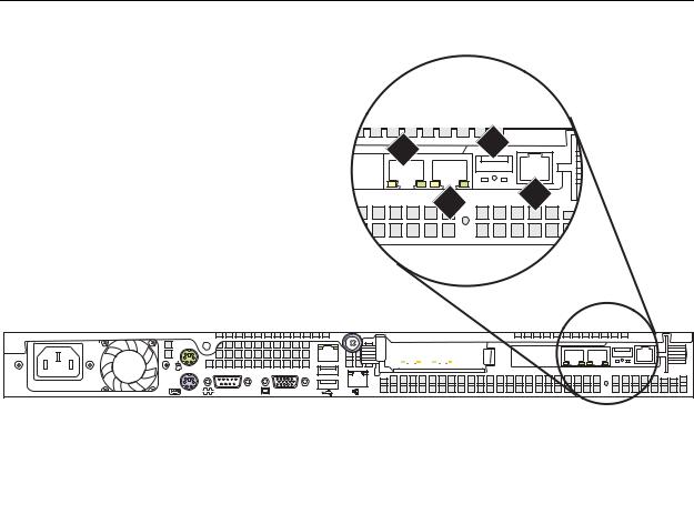
Figure 5: SAMP connections for S8500B shows the locations of the connections on the SAMP for the S8500B. Figure 5: SAMP connections for S8500B on page 17 shows the locations of the connections on the SAMP for the S8500C.
Figure 5: SAMP connections for S8500B
1 3
2 4
2 |
h2ms85bs LAO 051706 |
Figure notes:
1. |
SAMP Eth2—to the services laptop |
3. |
USB connection for the modem |
|
computer (cross-connect CAT5 cable) |
4. |
External power to the SAMP |
2. |
SAMP Eth1 (not used) |
|
|
|
|
|
|
Installing and Configuring the Avaya S8500 Media Server |
February 2007 17 |
Chapter 1: Introduction
Figure 6: SAMP connections for S8500C
Slot 2 |
Slot 1 |
1 |
2 |
h2ms85cs LAO 051906 |
4 


 2
2


3 1
|
|
|
|
|
|
|
|
|
|
|
|
|
|
|
|
|
|
|
|
|
|
|
|
|
|
|
|
|
|
|
|
|
|
|
|
|
|
|
|
|
|
|
|
|
|
|
|
|
|
|
|
|
|
|
|
|
|
|
|
|
|
|
|
|
|
|
|
|
|
|
|
|
|
|
|
|
|
|
|
|
|
|
|
|
|
|
|
|
|
|
|
|
|
|
|
|
|
|
|
|
|
|
|
|
|
|
|
|
|
|
|
Figure notes: |
|
|
|||||||||||||||||||||||||
1. |
SAMP Eth2—to the services laptop |
3. |
USB connection for the modem |
||||||||||||||||||||||||
|
computer (cross-connect CAT5 cable) |
4. |
External power to the SAMP |
||||||||||||||||||||||||
2. |
SAMP Eth1 (not used) |
|
|
||||||||||||||||||||||||
|
|
|
|
|
|
|
|
|
|
|
|
|
|
|
|
|
|
|
|
|
|
|
|
|
|
|
|
About SAMP software
The SAMP is shipped from the factory with the software installed and with some default settings. However, you might need to install an updated version of the software, and you must configure the SAMP before you can use it.
If a SAMP software update file is available on the Avaya Support website, one of the preinstallation tasks required that you load the file on your laptop: see Using the Avaya Server Availability Management Processor (SAMP) (03-300322) for how to install software on the SAMP and change the default settings.
18 Installing and Configuring the Avaya S8500 Media Server |
February 2007 |
About media server port connections
About media server port connections
The following section explains how to connect the Ethernet ports on the back of the media server.
S8500 port connections
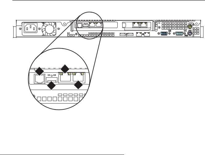
Use standard CAT5 cables with RJ45 connectors on each end to connect to the various ports. If the S8500 Media Server has only one port network, connect that port network through the dual NIC. Figure 7: S8500B Media Server connectivity guide shows typical connectivity for the S8500B Media Server. Figure 8: S8500C Media Server connectivity guide on page 20 shows typical connectivity for the S8500C Media Server.
Figure 7: S8500B Media Server connectivity guide
2
1
1 |


 4
4


 2
2
h3msbl5d LAO 052506
3
1


 2
2
Figure notes:
1.Eth0—To the customer network if the control network is shared. Or, to the control-network Ethernet switch if the control network is dedicated (straight-through CAT5 cable)
2.Eth1—To the Services laptop computer (cross-over CAT5 cable)
3.Eth2—to the customer network if the control network is dedicated (straight-through CAT5 cable)
4.Eth3—Not used
Installing and Configuring the Avaya S8500 Media Server |
February 2007 19 |
Chapter 1: Introduction
Figure 8: S8500C Media Server connectivity guide
 3
3
4
Slot 2
Slot 1
1 |
2 |
h2msb8cp LAO 052506
 2
2
 1
1


 1
1 

2
Figure notes:
1.Eth0—To the customer network if the control network is nondedicated. Or, to the control-network Ethernet switch if the control network is dedicated (straight-through CAT5 cable)
2.Eth1—To the Services laptop computer (cross-over CAT5 cable)
3.Eth3—to the customer network if the control network is dedicated (straight-through CAT5 cable)
4.Eth4—Not used
Note:
If the S8500C is configured as an ESS, the port assignments are different:
●Eth0: Control Network A
●Eth3: Control Network B
●Eth4: LAN, if two dedicated control networks are used
In either case, ETH2 is an internal port dedicated to the SAMP.
20 Installing and Configuring the Avaya S8500 Media Server |
February 2007 |
About modem connections
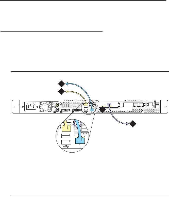
About modem connections
Note:
You cannot connect USB modems to rotary lines. A touch tone line is required. On an Avaya S8500 Media Server, connect the modem to the USB port on the SAMP.
Avaya defaults on the SAMP set the required options on the SAMP modem. For modem connectivity, see Figure 9: Modem connectivity on the S8500 Media Server.
Figure 9: Modem connectivity on the S8500 Media Server
3 
2
1
Multi |
Modem |
|
Multi |
|
S |
oftwTech |
|
are |
disc
Figure notes: |
|
|
1. |
Modem |
3. Telephone line that connects the modem |
2. |
USB cable that connects the USB modem |
to the outside line |
|
to the USB port on the media server |
|
|
|
|
Installing and Configuring the Avaya S8500 Media Server |
February 2007 21 |

Chapter 1: Introduction
Modem options
You set the modem options when you configure the media server. You do not set options on the modems themselves.
About media gateways
In a new installation, the Avaya S8500 Media Server works with only the Avaya G650 Media Gateway.
In a migration, the media server works with the following Avaya media gateways:
●SCC1
●G600
●CMC1
The media servers also work with Avaya G150, G250, G350, and G700 Media Gateways. These gateways register with the media server either through the Processor Ethernet interface or through a TN799DP C-LAN circuit pack.
With an S8500 Media Server, these media gateways can be endpoints that use a Processor Ethernet interface.
Media gateways usually are installed in the same equipment room as the media server rack hardware or control network. However, you can install the media gateways in another location, including another state or country.
About Processor Ethernet
Like a C-LAN circuit pack, Processor Ethernet provides connectivity to IP endpoints, gateways, and adjuncts. The PE interface is a logical connection in the Communication Manager software that uses a port on the NIC in the server. No additional hardware is needed to implement PE.
Starting with Release 3.1 of Communication Manager, the PE interface is enabled on the S8500 Media Server to allow enhanced flexibility to connect to gateways, endpoints, and adjuncts.
22 Installing and Configuring the Avaya S8500 Media Server |
February 2007 |
About Processor Ethernet
.Table 4 lists the possible uses of the PE interface for an S8500 primary controller.
Table 4: Use of the PE interface for a simplex S8500 primary controller
Possible functions of |
Status of the function |
Administration needed? |
the PE interface |
on the S8500 Media |
|
|
Server |
|
|
|
|
Registration |
The PE interface is |
No. The Communication Manager |
|
enabled for registration |
software automatically enables the |
|
on a simplex main server. |
use of the PE interface for |
|
|
registration. |
|
|
|
H.248 gateway |
H.248 gateway |
Yes. You perform the administration |
registration |
registration is allowed on |
to allow H.248 registration on the PE |
|
the S8500 main server |
interface of the S8500 main server on |
|
using the PE interface. |
the ip-interfaces procr form. |
|
|
|
H.323 endpoint |
H.323 registration is |
Yes. You perform administration to |
registration |
allowed on the S8500 |
allow H.323 registration of the PE |
|
main server using the PE |
interface of the S8500 main server on |
|
interface. |
the ip-interfaces procr form. |
|
|
|
Adjunct connectivity |
Adjunct connectivity is |
Yes. To administer adjuncts, you must |
|
allowed on the S8500 |
use the ip-services form or the |
|
main server using the PE |
communication-interface |
|
interface. |
processor-channels form before the |
|
|
survivable-processor form. |
|
|
|
|
|
|
Installing and Configuring the Avaya S8500 Media Server |
February 2007 23 |

Chapter 1: Introduction
About S8500 LSP mode
Starting with Release 3.1 of Communication Manager, you can configure the S8500 as a local survivable processor (LSP), and, the S8500 can be the primary controller for an IP network with port networks. This new functionality is enabled by allowing H.248 gateways and H.323 endpoints to use the Processor Ethernet (PE) interface of the S8500 instead of a C-LAN interface to register with the S8500.
Table 5 lists the possible uses of the PE interface for an S8500 LSP.
Table 5: Use of the PE interface on the S8500 LSP
Possible |
Status of the function |
Administration needed |
functions of |
on the LSP server |
|
the PE |
|
|
interface |
|
|
|
|
|
Registration |
The PE interface is |
No. The Communication Manager software |
|
always enabled for |
automatically enables the use of the PE |
|
registration. |
interface for registration. |
|
|
|
H.248 gateway |
H.248 gateway |
No. The H.248 gateway enabled field on the |
registration |
registration is enabled by |
ip-interface procr form defaults to yes on an |
|
default. |
LSP. To temporarily disable H.248 registration |
|
|
on the LSP, you can change the ip-interfaces |
|
|
procr form on the LSP. Any change that you |
|
|
perform on the LSP is lost when the LSP |
|
|
receives a file sync from the main server. After |
|
|
a file sync H.248 gateway registration will |
|
|
default to yes. |
|
|
|
H.323 endpoint |
H.323 endpoint |
No. The H.248 gateway enabled field on the |
registration |
registration is enabled by |
ip-interface procr form defaults to yes on an |
|
default. |
LSP. To temporarily disable H.248 registration |
|
|
on the LSP, you can change the ip-interfaces |
|
|
procr form on the LSP. Any change that you |
|
|
perform on the LSP is lost when the LSP |
|
|
receives a file sync from the main server. After |
|
|
a file sync, H.248 gateway registration |
|
|
defaults to yes. |
|
|
|
Adjunct |
Adjunct connectivity is |
Yes. You must perform adjunct administration |
connectivity |
enabled by default. |
for the LSP on the main server. |
|
|
|
|
|
|
24 Installing and Configuring the Avaya S8500 Media Server |
February 2007 |

S8500 LSP license file
The PE interface on an S8500 LSP supports three adjuncts:
●Call Management System (CMS)
●Application Enablement Services (AESVCS)
●Call Detail Recording (CDR)
The S8500 as a primary controller can connect to gateways and endpoints that use both C-LANs and the PE interface. The traffic over these interfaces can be load balanced.
S8500 LSP license file
The license file for an LSP must have the following attributes:
●The Local Survivable Processor (FEAT_LSP) field is set to y.
●A Module ID (MID) that is greater than 1. This value is set by the license file and cannot be administered in Communication Manager.
●A System ID (SID). The SID is unique to the system configuration. The primary controller and all LSPs have the same SID.
●The serial number of an H.248 media gateway to serve as the license serial number host.
During initial installation, when the LSP server is reset, the LSP sends this serial number to the primary controller. The primary controller then matches the serial number to the serial number of an existing media gateway. The primary controller sends the IP address of the media gateway back to the LSP. To verify the license, the LSP can then contact that media gateway and request the serial number. The LSP compares the serial number from the media gateway with the serial number from the license of the LSP.
About SSH
Secure Shell (SSH) is both a computer program and an associated network protocol that you use to log in to and run commands on a networked computer. SSH provides secure encrypted communications between two untrusted hosts over an insecure network. Avaya strongly recommends that you use SSH instead of Telnet for most interactive connections to the Avaya media servers and other devices on a customer network.
To use SSH, a third-party SSH client must be installed on your computer. PuTTY is one such client. You can download PuTTY from http://www.putty.nl/download.html.
Installing and Configuring the Avaya S8500 Media Server |
February 2007 25 |

Chapter 1: Introduction
You can use SSH to access the following devices:
●The S8300, S8400, S8500, and S8700-series Media Servers on Release 3.1 or later of Communication Manager
Note:
With Release 4.0 or later of Communication Manager, Telnet is disabled, so you must use SSH to access the media servers after Communication Manager software Release 4.0 or later is installed.
●A Server Availability Management Processor (SAMP), which is used with the S8500 Media Server
●A Maintenance Processor Complex (MPC), which is used with the S8400 Media Server
●A TN2312BP IPSI that is running firmware version 20 or higher
●A TN8412AP SIPI
●A TN2602 IP Media Resource 360 that is running firmware version 212 or higher
●An Expanded Meet-Me Conferencing (EMMC) server
●A SIP Enablement Services (SES) server
●G250 and G350 media gateways
●C360 Ethernet switches
!Important:
You cannot use SSH with the G700. From within the Linux command line of a media server, you can use SSH to access the G250 and the G350, but you must use Telnet to access the G700.
26 Installing and Configuring the Avaya S8500 Media Server |
February 2007 |

Configuring the SNMP modules in the UPS
Chapter 2: SNMP Configuration
After you install and connect the control network equipment, you must configure the SNMP modules in each Avaya-supplied UPS to send alarms or traps to the media servers. This process requires that you also configure the SNMP subagent in the Avaya-supplied Ethernet switch.
!Important:
Use the procedures in this section to configure Avaya-supplied equipment only.
Configuring the SNMP modules in the UPS
!Important:
These procedures apply only to a new, Avaya-supplied uninterruptible power supply (UPS) with a Simple Network Management Protocol (SNMP) module. Do not use these procedures to set traps on a UPS that Avaya does not supply.
You must configure the SNMP module in the UPS to report alarms to the media server when hardware problems occur. The module reports an alarm if commercial power is lost or battery resources are depleted.
For the SNMP module to properly report alarms, you must configure a unique IP address for the UPS on both the SNMP module and the media server. This IP address can be a customer-provided address or the Avaya-provided default address. At a minimum, you must configure the following items:
●The IP address
●The subnet mask
●The gateway IP address
●The trap receiver IP address
●The community string (get, set, trap)
A third party manufactures the SNMP module. The brand, the model, or the firmware load of the module that Avaya supplies can change without notice. For this reason, this document does not provide specific instructions on how to connect to and configure the SNMP module. For more information, see the documentation that comes with the SNMP module. For the default password and the configuration commands, see the local configuration section of that user guide.
Installing and Configuring the Avaya S8500 Media Server |
February 2007 27 |

Chapter 2: SNMP Configuration
Default IP addresses for the UPS
The following table shows the default IP addresses for the UPS.
IP address for the UPS |
198.152.254.239 |
|
|
Subnet mask for the UPS |
255.255.255.0 |
|
|
Gateway address for the UPS |
198.152.254.201 |
|
|
IP address for the |
Customer provided |
trap receiver (media server) |
|
|
|
For how to administer the SNMP module in the UPS, see Administering the SNMP module on page 29.
Prerequisites for configuring the SNMP module
Before you configure the SNMP module, you must complete the following prerequisites:
●Your Services laptop computer is plugged into the correct administration port on the SNMP module.
●The UPS is plugged into a nonswitched electrical outlet.
●The communication protocol on your computer has the following port settings so that you can use your terminal emulation program:
-9600 baud
-No parity
-8 data bits
-1 stop bit
-No flow control
Note:
Avaya Terminal Emulation and HyperTerminal are supported terminal emulation applications.
●If a Network Management System (NMS) is to monitor the UPS, you coordinated the assignment of community names with the network administrator. If an NMS is not used, you set the community names to unique string values.
28 Installing and Configuring the Avaya S8500 Media Server |
February 2007 |

Configuring the SNMP modules in the UPS
!SECURITY ALERT:
The Get and Set community name strings are initially configured with the default values of Public and Private, respectively. These community name strings function as passwords for their respective SNMP operation. Avaya recommends that you change these community name strings to something other than the default values. If you leave the defaults in place, a serious security issue can result.
For information about which traps to set, see Setting selected traps (alarming) on page 30.
●If the control network is nondedicated, ensure that the 162/udp port for input to server is enabled and the default is disabled. If you do not enable the 162/udp port and disable the default, the media server cannot receive the traps from either UPS. See Enabling firewall settings on page 44.
Administering the SNMP module
Note:
Use the default IP addresses.
1.Connect the RS-232 serial port of your Services laptop computer to the DB-9 connector on the back of the SNMP module for UPS1. Use the DB-9 to DB-9 serial cable that is supplied with the SNMP module.
2.Open a VT-100 terminal emulation session on your computer.
3.Set the IP address for the UPS.
4.Set the subnet mask for the UPS.
5.Set the gateway address for the UPS.
6.Set the IP address of the trap receiver for the UPS.
7.Set the SNMP community name string for Get, Set, and Trap. For information on which traps to set, see Setting selected traps (alarming) on page 30.
8.When you finish, disconnect your computer from the UPS.
9.Connect one end of a CAT5 straight-through cable to the RJ45 connector on the UPS SNMP module and the other end of the cable to the next available port on the Ethernet switch for Control Network A (CNA).
For a connectivity guide, see the Quick Start for Hardware Installation: Avaya S8500 Media Server (555-245-701).
After you configure the SNMP module in the UPS, you must configure the SNMP subagent on the Avaya Ethernet switch.
Installing and Configuring the Avaya S8500 Media Server |
February 2007 29 |

Chapter 2: SNMP Configuration
Setting selected traps (alarming)
The default is to set all traps, which can result in large log entries. To avoid this problem, Avaya recommends that you set only the following traps:
●UPS on Battery—Indicates an AC power failure. Based on the level of battery reserve, a shutdown is pending.
●UPS in Bypass—The UPS failed or is overloaded.
●Replace battery—The battery failed the 28-day battery test and must be replaced.
For the menus and commands to set these traps, see the user guide that comes with the SNMP module.
Configuring the SNMP subagent in the Avaya Ethernet switch (if used)
!Important:
These procedures apply only to a new, Avaya-supplied uninterruptible power supply (UPS) with a Simple Network Management Protocol (SNMP) module. Do not use these procedures to set traps on a UPS that Avaya does not supply.
You must administer the Simple Network Management Protocol (SNMP) subagent in the Avaya Ethernet switch to report alarms to the media server when problems occur.
For the SNMP module to properly report alarms, you must configure a unique IP address for the UPS on both the SNMP module and the media server. This IP address can be a customer-provided address or the Avaya-provided default address. At a minimum, you must configure the following items:
●The IP address
●The subnet mask
●The gateway IP address
●The trap receiver IP address
●The community string (get, set, trap)
The brand, the model, or the firmware load of the Ethernet switch that Avaya supplies can change without notice. For this reason, this document does not provide specific instructions on how to connect to and configure the SNMP subagent. For more information, see the documentation that comes with the Ethernet switch. Also see the Basic Configuration section of the Quick Start Guide and the documentation CD-ROM that comes with the Ethernet switch for the default user ID, password, and configuration commands.
30 Installing and Configuring the Avaya S8500 Media Server |
February 2007 |
Loading...