


 Loading...
Part No. P0606013 02
Business Communications
Manager (version 3.5 software)
DECT Installation and
Maintenance Guide
2
Copyright © 2003 Nortel Networks
All rights reserved. September, 2003.
The information in this document is subject to change without notice. The statements, configurations, technical data, and recommendations in this document are believed to be accurate and reliable, but are presented without express or implied warranty. Users must take full responsibility for their applications of any products specified in this document. The information in this document is proprietary to Nortel Networks NA Inc.
Trademarks
NORTEL NETWORKS is a trademark of Nortel Networks.
Microsoft, MS, MS-DOS, Windows, and Windows NT are registered trademarks of Microsoft Corporation.
All other trademarks and registered trademarks are the property of their respective owners.
DECT regulatory information
The CE Marking on this equipment indicates compliance with the following:
This device conforms to Directive 1999/5/EC on Radio Equipment and Telecommunications Terminal Equipment as adopted by the European Parliament And Of The Council.
This is a class A product. In a domestic environment this product may cause radio interference in which case the user may be required to take adequate measures.
Hereby, Nortel Networks declares that Enterprise Edge/ Business Communications Manager Model No. NT7B10xxxx, is in compliance with the essential requirements and other relevant provisions of Directive 1999/5/EC.
The C4010/C4020 handset is in compliance with Council Recommendation 1999/519/EC.
The DECT Base Station shall be cabled from host PBX controller card via individually screened paired cable.
The DECT standard is an integrated solution for cordless communication services based upon these ETSI specifications:
•ETS 300-175: Digital Enhanced Cordless Telephone Common Interface
•ETS 300-176: Digital Enhanced Cordless Telephone approval test specification
•ETS 300-444: Digital Enhanced Cordless Telephone General Access Profile
The DECT module provides an interface to the Business Communications Manager for cordless handsets through a radio link with a base station connected directly to the DECT module. The interface is created by linking four BRI loops and a Mercator C8 PBX through a BRI within the module circuitry.
P0606013 02

3
Electromagnetic compatibility
DECT standard complies with the following safety and electromagnetic compatibility recommendations:
•ETS 300329:Radio Equipment Systems; Electromagnetic Compatibility for Digital Enhanced
Cordless Telephone.
•EN 60950: Safety of Information Technology Equipment.
•EN 55022: Electromagnetic Compatibility for Information Technology Equipment.
DECT Installation and Maintenance Guide

4
P0606013 02

5
Contents
DECT regulatory information . . . . . . . . . . . . . . . . . . . . . . . . . . . . . . . . . . . . . . . . . . . . . 2 Electromagnetic compatibility . . . . . . . . . . . . . . . . . . . . . . . . . . . . . . . . . . . . . . . . . 3
Preface . . . . . . . . . . . . . . . . . . . . . . . . . . . . . . . . . . . . . . . . . . . . . . . . . . . . . . 13
Symbols Used in this Guide . . . . . . . . . . . . . . . . . . . . . . . . . . . . . . . . . . . . . . . . . . . . |
13 |
Text Conventions Used in This Guide . . . . . . . . . . . . . . . . . . . . . . . . . . . . . . . . . . . . . |
14 |
Acronyms . . . . . . . . . . . . . . . . . . . . . . . . . . . . . . . . . . . . . . . . . . . . . . . . . . . . . . . . . . . |
14 |
Related Publications . . . . . . . . . . . . . . . . . . . . . . . . . . . . . . . . . . . . . . . . . . . . . . . . . . |
15 |
Chapter 1
DECT system overview and requirements . . . . . . . . . . . . . . . . . . . . . . . . . 17
DECT features . . . . . . . . . . . . . . . . . . . . . . . . . . . . . . . . . . . . . . . . . . . . . . . . . . . . . . . 19
Business Communications Manager features . . . . . . . . . . . . . . . . . . . . . . . . . . . . 19 Handset features . . . . . . . . . . . . . . . . . . . . . . . . . . . . . . . . . . . . . . . . . . . . . . . . . . 20
Setup process overview . . . . . . . . . . . . . . . . . . . . . . . . . . . . . . . . . . . . . . . . . . . . . . . . 21 DECT base station deployment planning . . . . . . . . . . . . . . . . . . . . . . . . . . . . . . . . . . 22 DECT radio base station . . . . . . . . . . . . . . . . . . . . . . . . . . . . . . . . . . . . . . . . . . . . . . . 22 External antennas . . . . . . . . . . . . . . . . . . . . . . . . . . . . . . . . . . . . . . . . . . . . . . . . . 23 Specifications for DECT radio base stations . . . . . . . . . . . . . . . . . . . . . . . . . . . . . 25 Base station notes: . . . . . . . . . . . . . . . . . . . . . . . . . . . . . . . . . . . . . . . . . . . . . . . . 26 Climatic conditions . . . . . . . . . . . . . . . . . . . . . . . . . . . . . . . . . . . . . . . . . . . . . 26 Power supply . . . . . . . . . . . . . . . . . . . . . . . . . . . . . . . . . . . . . . . . . . . . . . . . . 26 Description of the connection . . . . . . . . . . . . . . . . . . . . . . . . . . . . . . . . . . . . . . . . 26
DECT cordless handsets . . . . . . . . . . . . . . . . . . . . . . . . . . . . . . . . . . . . . . . . . . . . . . . 27 Site configurations . . . . . . . . . . . . . . . . . . . . . . . . . . . . . . . . . . . . . . . . . . . . . . . . . . . . 27 DECT call paths . . . . . . . . . . . . . . . . . . . . . . . . . . . . . . . . . . . . . . . . . . . . . . . . . . . . . . 27 DECT programming overview . . . . . . . . . . . . . . . . . . . . . . . . . . . . . . . . . . . . . . . . . . . 28 DECT interface commands . . . . . . . . . . . . . . . . . . . . . . . . . . . . . . . . . . . . . . . . . . 28 Numbering plan syntax . . . . . . . . . . . . . . . . . . . . . . . . . . . . . . . . . . . . . . . . . . . . . 29 Business Communications Manager requirements . . . . . . . . . . . . . . . . . . . . . . . . . . . 29 Checking the System Region . . . . . . . . . . . . . . . . . . . . . . . . . . . . . . . . . . . . . . . . . . . 30
Chapter 2
Installing the DECT media bay module . . . . . . . . . . . . . . . . . . . . . . . . . . . . 31
Setting the DIP switches . . . . . . . . . . . . . . . . . . . . . . . . . . . . . . . . . . . . . . . . . . . . . . . 32 Installing the DECT module . . . . . . . . . . . . . . . . . . . . . . . . . . . . . . . . . . . . . . . . . . . . . 34 Restoring the system . . . . . . . . . . . . . . . . . . . . . . . . . . . . . . . . . . . . . . . . . . . . . . 35
Chapter 3
Configuring the DECT module . . . . . . . . . . . . . . . . . . . . . . . . . . . . . . . . . . . 37
Process overview: Identify and configure the DECT Module . . . . . . . . . . . . . . . . . . . . 38 Confirming the DECT module . . . . . . . . . . . . . . . . . . . . . . . . . . . . . . . . . . . . . . . . . . . 39
DECT Installation and Maintenance Guide

6 Contents
Configuring the module for µ-law . . . . . . . . . . . . . . . . . . . . . . . . . . . . . . . . . . . . . . . . . |
40 |
Before you start . . . . . . . . . . . . . . . . . . . . . . . . . . . . . . . . . . . . . . . . . . . . . . . . . . . |
40 |
Setting up the DECT file for upload . . . . . . . . . . . . . . . . . . . . . . . . . . . . . . . . . . . . |
41 |
Resetting the module to default values . . . . . . . . . . . . . . . . . . . . . . . . . . . . . . . . . |
42 |
Checking the Unified Manager handset DNs . . . . . . . . . . . . . . . . . . . . . . . . . . . . . . . . |
43 |
Setting up the handsets . . . . . . . . . . . . . . . . . . . . . . . . . . . . . . . . . . . . . . . . . . . . . . . . |
44 |
Stand-alone handset . . . . . . . . . . . . . . . . . . . . . . . . . . . . . . . . . . . . . . . . . . . . . . . |
45 |
Assigning routes or lines . . . . . . . . . . . . . . . . . . . . . . . . . . . . . . . . . . . . . . . . |
45 |
Assigning target lines . . . . . . . . . . . . . . . . . . . . . . . . . . . . . . . . . . . . . . . . . . . |
45 |
Assigning handsets to fixed telephone DNs . . . . . . . . . . . . . . . . . . . . . . . . . . . . . |
46 |
Handset feature programming . . . . . . . . . . . . . . . . . . . . . . . . . . . . . . . . . . . . . . . . |
46 |
About the DECT Wizards . . . . . . . . . . . . . . . . . . . . . . . . . . . . . . . . . . . . . . . . . . . . . . |
47 |
Understanding the DECT Configuration Wizard . . . . . . . . . . . . . . . . . . . . . . . . . . |
47 |
Before you start . . . . . . . . . . . . . . . . . . . . . . . . . . . . . . . . . . . . . . . . . . . . . . . |
47 |
Using the Configuration Wizard . . . . . . . . . . . . . . . . . . . . . . . . . . . . . . . . . . . . . . |
49 |
Setting up the module Time Synch . . . . . . . . . . . . . . . . . . . . . . . . . . . . . . . . . . . . |
50 |
Chapter 4
Installing the DECT base station . . . . . . . . . . . . . . . . . . . . . . . . . . . . . . . . . 53
Installing base station hardware . . . . . . . . . . . . . . . . . . . . . . . . . . . . . . . . . . . . . . . . . 53 Special considerations . . . . . . . . . . . . . . . . . . . . . . . . . . . . . . . . . . . . . . . . . . . . . 53 Installing the base station on the wall . . . . . . . . . . . . . . . . . . . . . . . . . . . . . . . . . . 54 Base station connections . . . . . . . . . . . . . . . . . . . . . . . . . . . . . . . . . . . . . . . . . . . 55 Connecting the base station to the system . . . . . . . . . . . . . . . . . . . . . . . . . . . . . . . . . 56 Checking the base station wiring . . . . . . . . . . . . . . . . . . . . . . . . . . . . . . . . . . . . . 56 Attaching the base station to the module . . . . . . . . . . . . . . . . . . . . . . . . . . . . . . . 57 Base station antennas . . . . . . . . . . . . . . . . . . . . . . . . . . . . . . . . . . . . . . . . . . . . . . . . . 58 Attaching external antennas to the base station . . . . . . . . . . . . . . . . . . . . . . . . . . 59
Chapter 5
Subscribing DECT cordless handsets . . . . . . . . . . . . . . . . . . . . . . . . . . . . . 61
Process map: subscribing the handsets . . . . . . . . . . . . . . . . . . . . . . . . . . . . . . . . . . . 62 Base station recording status . . . . . . . . . . . . . . . . . . . . . . . . . . . . . . . . . . . . . . . . . . . 63 DECT Mobile Recording (Handset Subscription) Wizard . . . . . . . . . . . . . . . . . . . 63 Before you start . . . . . . . . . . . . . . . . . . . . . . . . . . . . . . . . . . . . . . . . . . . . . . . . . . . 63 Filling out the Mobile Recording (Handset Subscription) Wizard . . . . . . . . . . . . . 64 Turning off mobile recording . . . . . . . . . . . . . . . . . . . . . . . . . . . . . . . . . . . . . . 64 Subscribing DECT cordless handsets . . . . . . . . . . . . . . . . . . . . . . . . . . . . . . . . . . . . . 65 Handset buttons . . . . . . . . . . . . . . . . . . . . . . . . . . . . . . . . . . . . . . . . . . . . . . . . . . 65 Subscribing a handset . . . . . . . . . . . . . . . . . . . . . . . . . . . . . . . . . . . . . . . . . . . . . . 66 Resetting the base station . . . . . . . . . . . . . . . . . . . . . . . . . . . . . . . . . . . . . . . . . . . 67 Checking handset status . . . . . . . . . . . . . . . . . . . . . . . . . . . . . . . . . . . . . . . . . . . . 68 Confirming base station readiness . . . . . . . . . . . . . . . . . . . . . . . . . . . . . . . . . . . . 69
P0606013 02

Contents 7
Setup test . . . . . . . . . . . . . . . . . . . . . . . . . . . . . . . . . . . . . . . . . . . . . . . . . . . . . . . 71 Handset system features . . . . . . . . . . . . . . . . . . . . . . . . . . . . . . . . . . . . . . . . . . . . . . . 71 Hunt groups . . . . . . . . . . . . . . . . . . . . . . . . . . . . . . . . . . . . . . . . . . . . . . . . . . . . . . 72 Message Waiting Indicator (MWI) . . . . . . . . . . . . . . . . . . . . . . . . . . . . . . . . . . . . . 72 Programming the MWI lamp button . . . . . . . . . . . . . . . . . . . . . . . . . . . . . . . . 73 Twinning features . . . . . . . . . . . . . . . . . . . . . . . . . . . . . . . . . . . . . . . . . . . . . . . . . 73 CallPilot programming . . . . . . . . . . . . . . . . . . . . . . . . . . . . . . . . . . . . . . . . . . . . . . 73 Auto-answer issues . . . . . . . . . . . . . . . . . . . . . . . . . . . . . . . . . . . . . . . . . . . . . . . . 73 Receiving a page . . . . . . . . . . . . . . . . . . . . . . . . . . . . . . . . . . . . . . . . . . . . . . . . . 74 Roaming . . . . . . . . . . . . . . . . . . . . . . . . . . . . . . . . . . . . . . . . . . . . . . . . . . . . . . . . 74 Roaming on outgoing calls . . . . . . . . . . . . . . . . . . . . . . . . . . . . . . . . . . . . . . . 75 Direct Inward Roaming . . . . . . . . . . . . . . . . . . . . . . . . . . . . . . . . . . . . . . . . . . 75
Chapter 6 |
|
Programming DECT module defaults . . . . . . . . . . . . . . . . . . . . . . . . . . . . . |
77 |
Accessing the Maintenance Console . . . . . . . . . . . . . . . . . . . . . . . . . . . . . . . . . . . . . |
78 |
System Management . . . . . . . . . . . . . . . . . . . . . . . . . . . . . . . . . . . . . . . . . . . . . . . . . . |
79 |
DECT and handset passwords . . . . . . . . . . . . . . . . . . . . . . . . . . . . . . . . . . . . . . . |
79 |
Language Management . . . . . . . . . . . . . . . . . . . . . . . . . . . . . . . . . . . . . . . . . . . . |
80 |
Card Management . . . . . . . . . . . . . . . . . . . . . . . . . . . . . . . . . . . . . . . . . . . . . . . . |
81 |
External antenna settings . . . . . . . . . . . . . . . . . . . . . . . . . . . . . . . . . . . . . . . . . . . . . . |
81 |
Chapter 7
Programming numbering plans and base stations . . . . . . . . . . . . . . . . . . 83
Planning your DECT settings . . . . . . . . . . . . . . . . . . . . . . . . . . . . . . . . . . . . . . . . . . . . 84 Setting DECT PARI values . . . . . . . . . . . . . . . . . . . . . . . . . . . . . . . . . . . . . . . . . . . . . 85 Telephony Management . . . . . . . . . . . . . . . . . . . . . . . . . . . . . . . . . . . . . . . . . . . . . . . 86 Outgoing Numbering Plan . . . . . . . . . . . . . . . . . . . . . . . . . . . . . . . . . . . . . . . . . . . . . . 87 User Numbering Plan . . . . . . . . . . . . . . . . . . . . . . . . . . . . . . . . . . . . . . . . . . . . . . 88 Incoming Call Numbering Plan . . . . . . . . . . . . . . . . . . . . . . . . . . . . . . . . . . . . . . . 89 Wireless Management . . . . . . . . . . . . . . . . . . . . . . . . . . . . . . . . . . . . . . . . . . . . . . . . . 91 Cell names . . . . . . . . . . . . . . . . . . . . . . . . . . . . . . . . . . . . . . . . . . . . . . . . . . . . . . 91 Managing Logical Trunks . . . . . . . . . . . . . . . . . . . . . . . . . . . . . . . . . . . . . . . . . . . 92
Chapter 8
Programming DECT handset records . . . . . . . . . . . . . . . . . . . . . . . . . . . . . 93
Confirming the DECT settings . . . . . . . . . . . . . . . . . . . . . . . . . . . . . . . . . . . . . . . . . . . 93 Identifying base stations . . . . . . . . . . . . . . . . . . . . . . . . . . . . . . . . . . . . . . . . . . . . 94 Mobile Management . . . . . . . . . . . . . . . . . . . . . . . . . . . . . . . . . . . . . . . . . . . . . . . . . . 96 Listing mobiles (handsets) . . . . . . . . . . . . . . . . . . . . . . . . . . . . . . . . . . . . . . . . . . 97 Identifying handsets . . . . . . . . . . . . . . . . . . . . . . . . . . . . . . . . . . . . . . . . . . . . . . . 98 Removing handsets . . . . . . . . . . . . . . . . . . . . . . . . . . . . . . . . . . . . . . . . . . . . . . . 98 Confirming the handset extension record . . . . . . . . . . . . . . . . . . . . . . . . . . . . . . . 99
DECT Installation and Maintenance Guide

8 Contents
Chapter 9
Maintaining and upgrading DECT software. . . . . . . . . . . . . . . . . . . . . . . . 103
Accessing the BRU screen, Unified Manager menu . . . . . . . . . . . . . . . . . . . . . . . . . 103 Accessing the BRU screen, DECT Tools menu . . . . . . . . . . . . . . . . . . . . . . . . . . . . . 104 Backup and Restore DECT module data . . . . . . . . . . . . . . . . . . . . . . . . . . . . . . . . . . 105 Backing up DECT data . . . . . . . . . . . . . . . . . . . . . . . . . . . . . . . . . . . . . . . . . . . . 105 Restoring DECT data . . . . . . . . . . . . . . . . . . . . . . . . . . . . . . . . . . . . . . . . . . . . . 107 Viewing the backup/restore schedule . . . . . . . . . . . . . . . . . . . . . . . . . . . . . . . . . 108
Chapter 10
Troubleshooting and Alarm Monitoring. . . . . . . . . . . . . . . . . . . . . . . . . . . 109
Radio base station fault on startup . . . . . . . . . . . . . . . . . . . . . . . . . . . . . . . . . . . . . . 109 Business Communications Manager application control . . . . . . . . . . . . . . . . . . . . . . 109 Viewing and changing the Maintenance Console status . . . . . . . . . . . . . . . . . . . . . . 111 Viewing and changing the DECT Alarm Monitor status . . . . . . . . . . . . . . . . . . . . . . . 112 Viewing alarms . . . . . . . . . . . . . . . . . . . . . . . . . . . . . . . . . . . . . . . . . . . . . . . . . . . . . 113 Base station/handset troubleshooting . . . . . . . . . . . . . . . . . . . . . . . . . . . . . . . . . . . . 113 Changing the TCPPort . . . . . . . . . . . . . . . . . . . . . . . . . . . . . . . . . . . . . . . . . . . . . . . 114 Monitoring the DECT module LEDs . . . . . . . . . . . . . . . . . . . . . . . . . . . . . . . . . . . . . 114 Determining module companding law setting . . . . . . . . . . . . . . . . . . . . . . . . . . . . . . 115
Appendix A
Quick reference to DECT module programming. . . . . . . . . . . . . . . . . . . . 117
Appendix B
Cordless handset verification. . . . . . . . . . . . . . . . . . . . . . . . . . . . . . . . . . . 121
Determining handset subscription . . . . . . . . . . . . . . . . . . . . . . . . . . . . . . . . . . . . . . . 121 Unsubscribing the handset . . . . . . . . . . . . . . . . . . . . . . . . . . . . . . . . . . . . . . . . . . . . 122 Testing the handset . . . . . . . . . . . . . . . . . . . . . . . . . . . . . . . . . . . . . . . . . . . . . . . . . . 123 Test mode icons . . . . . . . . . . . . . . . . . . . . . . . . . . . . . . . . . . . . . . . . . . . . . . . . . 124
Glossary . . . . . . . . . . . . . . . . . . . . . . . . . . . . . . . . . . . . . . . . . . . . . . . . . . . . 125
Index . . . . . . . . . . . . . . . . . . . . . . . . . . . . . . . . . . . . . . . . . . . . . . . . . . . . . . . 129
P0606013 02

9
Figures |
|
|
Figure 1 |
Integrated DECT service . . . . . . . . . . . . . . . . . . . . . . . . . . . . . . . . . . . . . |
18 |
Figure 2 |
Setup process for the DECT system . . . . . . . . . . . . . . . . . . . . . . . . . . . . |
21 |
Figure 3 |
Base station switches . . . . . . . . . . . . . . . . . . . . . . . . . . . . . . . . . . . . . . . . |
23 |
Figure 4 |
Antenna configurations . . . . . . . . . . . . . . . . . . . . . . . . . . . . . . . . . . . . . . |
24 |
Figure 5 |
Inside the DECT radio base station . . . . . . . . . . . . . . . . . . . . . . . . . . . . . |
25 |
Figure 6 |
Process for installing the DECT module . . . . . . . . . . . . . . . . . . . . . . . . . . |
31 |
Figure 7 |
Locating the DECT media bay module dip switches . . . . . . . . . . . . . . . . |
32 |
Figure 8 |
Release tabs for the module bays . . . . . . . . . . . . . . . . . . . . . . . . . . . . . . |
34 |
Figure 9 |
Front bezels replaced on units . . . . . . . . . . . . . . . . . . . . . . . . . . . . . . . . . |
35 |
Figure 10 |
Locating the LEDs on the DECT module face . . . . . . . . . . . . . . . . . . . . . |
36 |
Figure 11 |
Process for identifying and configuring the DECT module . . . . . . . . . . . . |
38 |
Figure 12 |
Maintenance Tools menu . . . . . . . . . . . . . . . . . . . . . . . . . . . . . . . . . . . . . |
41 |
Figure 13 |
Firmware upload . . . . . . . . . . . . . . . . . . . . . . . . . . . . . . . . . . . . . . . . . . . |
42 |
Figure 14 |
Restore default firmware configuration . . . . . . . . . . . . . . . . . . . . . . . . . . . |
42 |
Figure 15 |
Time synchronisation page . . . . . . . . . . . . . . . . . . . . . . . . . . . . . . . . . . . |
50 |
Figure 16 |
Base station with cover pulled away . . . . . . . . . . . . . . . . . . . . . . . . . . . . . |
54 |
Figure 17 |
RJ45 connectors on the media bay module . . . . . . . . . . . . . . . . . . . . . . . |
57 |
Figure 18 |
Status LED on outside of base station . . . . . . . . . . . . . . . . . . . . . . . . . . . |
58 |
Figure 19 |
Removing the internal antenna plate . . . . . . . . . . . . . . . . . . . . . . . . . . . . |
59 |
Figure 20 |
Process for subscribing the cordless handsets . . . . . . . . . . . . . . . . . . . . |
62 |
Figure 21 |
Define Radio Base Station ## DECT screen . . . . . . . . . . . . . . . . . . . . . . |
68 |
Figure 22 |
Wireless Management Menu menu . . . . . . . . . . . . . . . . . . . . . . . . . . . . . |
69 |
Figure 23 |
Wireless Resources Menu menu . . . . . . . . . . . . . . . . . . . . . . . . . . . . . . . |
69 |
Figure 24 |
Base Station Selection menu . . . . . . . . . . . . . . . . . . . . . . . . . . . . . . . . . . |
69 |
Figure 25 |
Define Radio Base Station XX DECT screen . . . . . . . . . . . . . . . . . . . . . . |
70 |
Figure 26 |
DECT interface, system management . . . . . . . . . . . . . . . . . . . . . . . . . . . |
77 |
Figure 27 |
Main DECT maintenance menu . . . . . . . . . . . . . . . . . . . . . . . . . . . . . . . . |
78 |
Figure 28 |
System Management menu . . . . . . . . . . . . . . . . . . . . . . . . . . . . . . . . . . . |
79 |
Figure 29 |
Password Management menu . . . . . . . . . . . . . . . . . . . . . . . . . . . . . . . . . |
79 |
Figure 30 |
Parameter Management menu . . . . . . . . . . . . . . . . . . . . . . . . . . . . . . . . . |
80 |
Figure 31 |
Wireless Resources menu . . . . . . . . . . . . . . . . . . . . . . . . . . . . . . . . . . . . |
81 |
Figure 32 |
Base station screen . . . . . . . . . . . . . . . . . . . . . . . . . . . . . . . . . . . . . . . . . |
82 |
Figure 33 |
DECT interface, trunk and cell management . . . . . . . . . . . . . . . . . . . . . . |
83 |
Figure 34 |
Wireless Management menu . . . . . . . . . . . . . . . . . . . . . . . . . . . . . . . . . . |
85 |
Figure 35 |
Wireless Topology menu . . . . . . . . . . . . . . . . . . . . . . . . . . . . . . . . . . . . . |
85 |
Figure 36 |
DECT parameters screen . . . . . . . . . . . . . . . . . . . . . . . . . . . . . . . . . . . . |
85 |
Figure 37 |
Telephony Management menu . . . . . . . . . . . . . . . . . . . . . . . . . . . . . . . . . |
86 |
Figure 38 |
Numbering Plan menu . . . . . . . . . . . . . . . . . . . . . . . . . . . . . . . . . . . . . . . |
87 |
Figure 39 |
User Numbering Plan menu . . . . . . . . . . . . . . . . . . . . . . . . . . . . . . . . . . . |
87 |
Figure 40 |
DECT directory numbers . . . . . . . . . . . . . . . . . . . . . . . . . . . . . . . . . . . . . |
88 |
DECT Installation and Maintenance Guide

10 Figures
Figure 41 |
Local Dialing List . . . . . . . . . . . . . . . . . . . . . . . . . . . . . . . . . . . . . . . . . . |
. 88 |
Figure 42 |
Incoming Call Numbering Plan menu . . . . . . . . . . . . . . . . . . . . . . . . . . . . |
89 |
Figure 43 |
Incoming plan: Internal numb. . . . . . . . . . . . . . . . . . . . . . . . . . . . . . . . . . 90 |
|
Figure 44 |
Local Dialing List . . . . . . . . . . . . . . . . . . . . . . . . . . . . . . . . . . . . . . . . . . . |
90 |
Figure 45 |
Wireless Management menu . . . . . . . . . . . . . . . . . . . . . . . . . . . . . . . . . . |
91 |
Figure 46 |
Wireless Topology menu . . . . . . . . . . . . . . . . . . . . . . . . . . . . . . . . . . . . . |
91 |
Figure 47 |
Wireless Resources menu . . . . . . . . . . . . . . . . . . . . . . . . . . . . . . . . . . . . |
92 |
Figure 48 |
Telephony Management menu . . . . . . . . . . . . . . . . . . . . . . . . . . . . . . . . . |
93 |
Figure 49 |
Wireless Management menu . . . . . . . . . . . . . . . . . . . . . . . . . . . . . . . . . . |
93 |
Figure 50 |
Wireless Resources menu . . . . . . . . . . . . . . . . . . . . . . . . . . . . . . . . . . . . |
94 |
Figure 51 |
Wireless Resources menu . . . . . . . . . . . . . . . . . . . . . . . . . . . . . . . . . . . . |
94 |
Figure 52 |
Base station screen . . . . . . . . . . . . . . . . . . . . . . . . . . . . . . . . . . . . . . . . . |
95 |
Figure 53 |
Wireless Mobiles menu . . . . . . . . . . . . . . . . . . . . . . . . . . . . . . . . . . . . . . |
97 |
Figure 54 |
Display Mobiles screen . . . . . . . . . . . . . . . . . . . . . . . . . . . . . . . . . . . . . . |
97 |
Figure 55 |
Create mobile record . . . . . . . . . . . . . . . . . . . . . . . . . . . . . . . . . . . . . . . . |
98 |
Figure 56 |
Telephony Management menu . . . . . . . . . . . . . . . . . . . . . . . . . . . . . . . . . |
99 |
Figure 57 |
Extension Data menu . . . . . . . . . . . . . . . . . . . . . . . . . . . . . . . . . . . . . . . . |
99 |
Figure 58 |
Extension Characteristics menu . . . . . . . . . . . . . . . . . . . . . . . . . . . . . . . . |
99 |
Figure 59 |
Handset record, page 1 . . . . . . . . . . . . . . . . . . . . . . . . . . . . . . . . . . . . . |
100 |
Figure 60 |
Handset record, page 2 . . . . . . . . . . . . . . . . . . . . . . . . . . . . . . . . . . . . . |
100 |
Figure 61 |
Handset record, page 3 . . . . . . . . . . . . . . . . . . . . . . . . . . . . . . . . . . . . . |
101 |
Figure 62 |
Maintenance Tools menu . . . . . . . . . . . . . . . . . . . . . . . . . . . . . . . . . . . . |
104 |
Figure 63 |
Backup and Restore Utility screen . . . . . . . . . . . . . . . . . . . . . . . . . . . . . |
105 |
Figure 64 |
Scheduling a backup, one time . . . . . . . . . . . . . . . . . . . . . . . . . . . . . . . |
106 |
Figure 65 |
Backup and Restore Utility screen . . . . . . . . . . . . . . . . . . . . . . . . . . . . . |
107 |
Figure 66 |
Backup and Restore Utility, restore screen . . . . . . . . . . . . . . . . . . . . . . |
107 |
Figure 67 |
Backup and Restore Utility screen . . . . . . . . . . . . . . . . . . . . . . . . . . . . . |
108 |
Figure 68 |
Backup and Restore Utility, schedule screen . . . . . . . . . . . . . . . . . . . . . |
108 |
Figure 69 |
Services list . . . . . . . . . . . . . . . . . . . . . . . . . . . . . . . . . . . . . . . . . . . . . . |
109 |
Figure 70 |
Services list for DECT Maintenance Console . . . . . . . . . . . . . . . . . . . . |
110 |
Figure 71 |
DECT Maintenance Console and Alarm Monitor . . . . . . . . . . . . . . . . . . |
111 |
Figure 72 |
DECT Maintenance Console and Alarm Monitor . . . . . . . . . . . . . . . . . . |
112 |
Figure 73 |
Alarm Banner . . . . . . . . . . . . . . . . . . . . . . . . . . . . . . . . . . . . . . . . . . . . . |
113 |
P0606013 02
11
Tables |
|
|
Table 1 |
Hardware components of the DECT system . . . . . . . . . . . . . . . . . . . . |
. . 18 |
Table 2 |
Parts of the DECT radio base station configurations . . . . . . . . . . . . . . |
. . 22 |
Table 3 |
Generated losses with extension cord added . . . . . . . . . . . . . . . . . . . . |
. 24 |
Table 4 |
DECT interface commands . . . . . . . . . . . . . . . . . . . . . . . . . . . . . . . . . . |
. 28 |
Table 5 |
Numbering plan syntax . . . . . . . . . . . . . . . . . . . . . . . . . . . . . . . . . . . . . |
. 29 |
Table 6 |
DECT switch settings . . . . . . . . . . . . . . . . . . . . . . . . . . . . . . . . . . . . . . . |
. 33 |
Table 7 |
Module settngs . . . . . . . . . . . . . . . . . . . . . . . . . . . . . . . . . . . . . . . . . . . . |
. 33 |
Table 8 |
Possible causes of interference . . . . . . . . . . . . . . . . . . . . . . . . . . . . . . . |
. 55 |
Table 9 |
Cable lengths and resistances . . . . . . . . . . . . . . . . . . . . . . . . . . . . . . . . |
. 56 |
Table 10 |
Base station LED conditions . . . . . . . . . . . . . . . . . . . . . . . . . . . . . . . . . |
. 58 |
Table 11 |
External antennas . . . . . . . . . . . . . . . . . . . . . . . . . . . . . . . . . . . . . . . . . |
. 59 |
Table 12 |
Troubleshooting the preliminary operations . . . . . . . . . . . . . . . . . . . . . . |
. 71 |
Table 13 |
Identifying cell, trunk and base station assignments . . . . . . . . . . . . . . . |
. 84 |
Table 14 |
Identify the outgoing and incoming numbering codes for your system |
. . 84 |
Table 15 |
DECT defaults: . . . . . . . . . . . . . . . . . . . . . . . . . . . . . . . . . . . . . . . . . . . . |
. 89 |
Table 16 |
Status options for DECT services . . . . . . . . . . . . . . . . . . . . . . . . . . . . . |
110 |
Table 17 |
Possible status settings . . . . . . . . . . . . . . . . . . . . . . . . . . . . . . . . . . . . . |
111 |
Table 18 |
Possible status settings . . . . . . . . . . . . . . . . . . . . . . . . . . . . . . . . . . . . . |
112 |
Table 19 |
Base station/handset troubleshooting . . . . . . . . . . . . . . . . . . . . . . . . . . |
113 |
Table 20 |
LED states . . . . . . . . . . . . . . . . . . . . . . . . . . . . . . . . . . . . . . . . . . . . . . . |
114 |
Table 21 |
Test mode icon definitions . . . . . . . . . . . . . . . . . . . . . . . . . . . . . . . . . . . |
124 |
DECT Installation and Maintenance Guide

12 Tables
P0606013 02
13
Preface
This guide describes how to install and initialize a DECT system. Information in these sections explain:
•how to set up and operate the DECT media bay module
•how to set up and operate the radio base stations
•how to subscribe the cordless handsets to the system
To use this guide, you must:
•be a Nortel Networks installer with Business Communications Manager certification
•know basic Nortel Networks terminology
•have a working Business Communications Manager system that is compatible with the DECT application
Symbols Used in this Guide
This guide uses symbols to draw your attention to important information. The following symbols appear in this guide:
Note: Note Symbol
A note alerts you to important information.
Tip: Tip Symbol
A tip adds general information pertinent to the current process.
Alerts you to ground yourself with an antistatic grounding strap before performing the maintenance procedure.
Alerts you to remove the Business Communications Manager server and Business Communications Manager Expansion Cabinet power cords from the a.c. outlet before performing the maintenance procedure.
Caution: Caution Symbol
Alerts you to conditions where you can damage the equipment.
Danger: Electrical Shock Hazard Symbol
Alerts you to conditions where you can get an electrical shock.
DECT Installation and Maintenance Guide

14 Preface
Warning: Warning Symbol
Alerts you to actions that can make the system non-operational.
Text Conventions Used in This Guide
This guide uses the following text conventions:
bold Courier text |
Indicates command names and options and text that you need to enter |
|
in a command-line interface. |
|
Example: Use the dinfo command. |
|
Example: Enter show ip {alerts|routes}. |
italic text |
Indicates file and directory names, new terms, book titles, Web |
|
addresses, and variables in command syntax descriptions. |
bold text |
Indicates command names, screen titles, options and text that you need |
|
to enter in a graphical user interface (GUI). |
angle brackets (< >) |
Indicates a keyboard key press or simultaneous key presses i.e. |
|
<ENTER> or <CTRL j> |
Acronyms
This guide uses the following acronyms:
AC |
Authentication code |
ADPCM |
Adaptive differential pulse code modulation |
ARI |
Access right identity |
BRI |
Basic rate interface (module) |
DECT |
Digital enhanced cordless telecommunications or Digital European cordless |
|
telephone |
DID |
Direct inward dial |
DSAA |
DECT standard authentication algorithm |
DTM |
Digital trunk module |
EIC |
Equipment installation code |
FPN + FPS |
Fixed part number and fixed part sub-number |
ISDN |
Integrated services digital network |
LAL |
Location area level |
LED |
Light-emitting diode |
MWI |
Message waiting indicator |
P0606013 02

Preface 15
PARI |
Primary access right identity |
PARK |
Portable access right key |
PARK{y} |
PARK with PLI y |
PBX |
Private branch exchange |
PLI |
Park length indicator |
PSTN |
Public switched telephone network |
RFPI |
Radio fixed park identity |
RSSI |
Radio signal strength indicator |
SARI |
Secondary ARI |
TCM |
Time compressor multiplexor |
WAN |
Wide area network |
Related Publications
For more information about the Business Communications Manager server and related media bay modules, extension equipment, and the applications and software on the system, refer to the following publications, which are located on the CD that came with your Business Communications Manager system or upgrade:
•Installation and Maintenance Guide describes the process of installing and maintaining the Business Communications Manager equipment. The book includes descriptions of the available modules.
•Programming Operations Guide describes how to program the Business Communications Manager equipment.
•If your Business Communications Manager has an internal voice mail system, refer to the documents specific to your system for setting up voice mail for your DECT handsets. If your system is part of a network connected to a Meridian system voice mail, refer to the Meridian voice mail documentation.
DECT Installation and Maintenance Guide

16 Preface
P0606013 02

17
Chapter 1
DECT system overview and requirements
The DECT system provides the Business Communications Manager with the ability to connect cordless telephones to the system for use within the local area.
There are specific Business Communications Manager profiles that can use this equipment. Refer to “Checking the System Region” on page 30. Other profiles are for countries that have other technology for this purpose.
Warning: Do not attempt to change a region setting on an active system. This can cause the system to reset and lose data.
This chapter describes the DECT system components and provides an overview of the installation process. It also includes instructions for ensuring that your Business Communications Manager is set to the correct profile to accept and work with the DECT equipment.
The information in this section includes:
•“DECT features” on page 19
•“Setup process overview” on page 21
•“DECT base station deployment planning” on page 22
•“DECT radio base station” on page 22
•“DECT cordless handsets” on page 27
•“Site configurations” on page 27
•“DECT call paths” on page 27
•“DECT programming overview” on page 28
•“Business Communications Manager requirements” on page 29
•“Checking the System Region” on page 30
Deployment and site preparation details are provided in a separate document. This section provides a brief overview of this task, as well as the specifications for the components.
This section also provides an overview of system operations. This includes the load required on the Business Communications Manager and general commands you require to work on the DECT interface.
DECT Installation and Maintenance Guide

18 Chapter 1 DECT system overview and requirements
The following figure shows a graphic representation of the components of the system.
Figure 1 Integrated DECT service
|
Handsets |
|
|
Base stations |
|
Business |
DECT media bay module |
|
Communications |
||
|
||
Manager |
|
The following table describes the three main hardware components of the DECT system.
Table 1 Hardware components of the DECT system
Component |
Function |
|
|
DECT media bay module |
The module connects up to eight radio base stations. Use the Business |
|
Communications Manager Unified Manager application to initialize and |
|
program the module. |
|
Within the module, four BRI ISDN loops allow up to eight simultaneous |
|
conversations. NOTE: Each Business Communications Manager system can |
|
support one DECT module. |
M6241 Radio base station |
Each base station provides radio coverage for a prescribed area. A group of |
|
base stations make up a cell. |
|
Each base station can support up to four simultaneous calls. The radio base |
|
stations also offer antenna diversity. |
|
Use the site survey to determine the number of base stations required to |
|
cover the area. Refer to “DECT base station deployment planning” on page |
|
22. |
|
|
DECT cordless handset |
Each handset provides the user with telephony features remote from the land |
C4010 and C4020 |
set. |
|
This book contains only the registration operations for the set. Refer to the |
|
user manuals that came with your handset for operational details. |
|
Up to 32 handsets can be assigned to each DECT system. |
|
|
P0606013 02

Chapter 1 DECT system overview and requirements 19
DECT features
The following list describes some of the special features of the DECT system.
•The DECT module contains four BRI ISDN-S loops. The Business Communications Manager assigns four loop records in the Unified Manager when the module is installed, based on the DIP switch settings for the module.
•The cordless handsets are identified with DNs in the Unified Manager. They can be assigned answer DNs to link them with stationary sets.
•The numbering plan and call routing defined in the Business Communications Manager must agree with the entries in the DECT interface.
Also refer to “Handset system features” on page 71.
Business Communications Manager features
The DECT system supports the following Business Communication Manager call processing features:
•autodial keys (handset-based)
•answer keys
•busy lamp indication
•call capture
—incoming calls can be redirected to the prime set or a voice mail box
Note: DECT handsets only can only access voice mailboxes (FEATURE 981) and receive only associated message waiting indicators (MWI) for new messages. Other voice mail functions, Call Center features, Attendant Console, TAPI applications or CTE applications are unavailable to DECT handsets. Symbol© NetVision© wireless handsets are the only portable system that supports these applications from the Business Communications Manager.
—a system telephone calling a DECT handset will continue to ring even after the handset ring timer runs out. It is recommended that all DECT handsets be set for Call Forward No Answer to deal with this issue.
•call display when busy: handsets will only get a busy signal
•call forward (all calls, busy, no answer)
•call identification: available, depending on system programming
•class of service/dialing restrictions
•conference calling
•delayed Ring Transfer to Prime if the DECT handset is not answered
•dial external/outgoing line identification
•intercom lines
•external line access using line pool codes or destination codes
•hold
DECT Installation and Maintenance Guide

20 Chapter 1 DECT system overview and requirements
•hunt group functionality
•multiple line appearances
•on hook dialing
•private lines (incoming)
•remote access
•ringing, restriction, and routing services
•set name
•target line (direct call from external line)
•transfer
•voice mail support to retrieve pending messages
Features not included on this list are not supported on the handset by the Business Communications Manager system.
Handset features
These features are provided by the DECT handset, and are not necessarily exclusive to Business Communications Manager operation.
•dial pad feedback
•feature access key
•headset
•hearing aid compatibility
•language choice
•last number redial
•on hook dialing from numbers stored in handset memory
•ringing line preference
•set speed dial
Refer to the DECT documentation that came with the handset for details.
P0606013 02
Chapter 1 DECT system overview and requirements 21
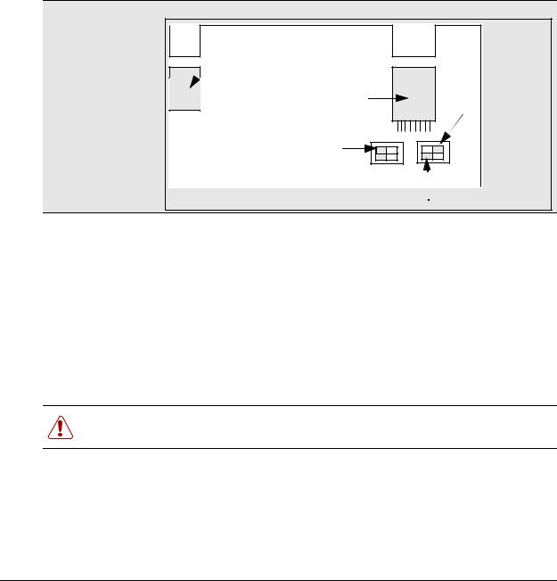
Setup process overview
The following figure provides an overview of the actions required to successfully set up the DECT integrated system:
Figure 2 Setup process for the DECT system
Plan the deployment
Check BCM system settings
Install media bay module
Install the radio base stations
stations to module
Program
the DECT
module
cordless handsets
Maintenance
tools
Have a site plan and deployment strategy worked out. Refer to the M6261DECT Deployment Tool Guide on the Business Communications Manager CD.
Data report |
Site survey |
Radio base stations locations |
Plan cells |
Ensure that your Business Communications Manager has the correct Region setting to allow DECT deployment. Refer to “Checking the System Region” on page 30.
Refer to Chapter 2, “Installing the DECT media bay module,” on page 31. This procedure assumes the Business Communications Manager is installed and commissioned.
Refer to Chapter 4, “Installing the DECT base station,” on page 53.
Check the site map for obstacles and possible sources of interference to the radio signal or data link.
The first radio base station must be within 800 m of the DECT media bay module. Attach the components using 0.6 mm cable.
Refer to “Configuring the DECT module” on page 37 for instructions about setting up the module through the Unified Manager, and running the DECT wizards. Chapters 6 to 8 provide instructions for manually configuring the DECT module settings.
Refer to Chapter 5, “Subscribing DECT cordless handsets,” on page 61. When the system and module DNs have been assigned, subscribe each handset. Test the handsets with each base station.
For some functions, DECT works separately from other applications on the Unified Manager. Use the tools found under the Maintenance button on the first page of the Unified Manager to perform these functions: Time synch, Firmware upload, Backup/Restore/Scheduling, Restore default, and viewing the current Companding law setting.
DECT Installation and Maintenance Guide

22 Chapter 1 DECT system overview and requirements
DECT base station deployment planning
The DECT base stations must be deployed to provide full site coverage with the maximum traffic capacity, using the minimum number of base stations.
There are two tasks involved in arranging this:
•Surveying the site: the site survey involves gathering information to determine customer requirements and the number of cells needed to support the traffic.
•Planning deployment: deployment plans establish the best locations for the radio base stations.
Site surveying and deployment planning are complex tasks, undertaken only by trained personnel. Refer to the M6261DECT Deployment Tool and site planning guide for detailed Site planning and deployment.
DECT radio base station
The Business Communications Manager can support one DECT media bay module.
The information in this section includes:
•“External antennas” on page 23
•“Specifications for DECT radio base stations” on page 25
•“Base station notes:” on page 26
•“Description of the connection” on page 26
A cable attached to an RJ45 connector in the face of the DECT module connects to the base station RJ45 connector. This supplies the data and power.
The base station comes with two internal antennas to provide signal diversity. Some types of external antennas can be substituted, depending on site requirements.
The following table describes the function of the parts of the base station.
Table 2 Parts of the DECT radio base station configurations
Part |
Description of function |
|
|
Base stations |
The area covered by the base station depends on the radio range. Base stations |
|
manage the links with the cordless handsets within that range. |
Cables |
The cable includes two telephone pairs. |
|
One transmits the signal. |
|
One receives the signal. |
|
|
Connectors |
The base station uses a female RJ45 to connect to the cable. |
|
|
P0606013 02
|
|
Chapter 1 DECT system overview and requirements 23 |
|
|
|
|
Table 2 |
Parts of the DECT radio base station configurations (continued) |
|
|
|
|
Part |
Description of function |
|
|
|
|
Switches |
There are two configuration switches: the CA1 and the S202. |
•The CA1 has two switches, labelled 1/2 and 3/4.
Set 1/2 to On to enable the adaptation resistor for the synchronization pair. Set 3/4 to On to enable base station Reset.
Set 3/4 to Off to run Reset by S0 interface level 1.
•The S202 has two switches, labelled 1/2 and 3/4.
Set 1/2 and 3/4 to On to enable the 100 ohm adaptation resistors for the S0 pairs.
Refer to Figure 3 on page 23.
Figure 3 Base station switches
Jack
RJ45
Reset
Adaptation RNIS |
4 |
2 4 |
2 |
|
3 |
1 3 |
1 |
S202On |
On |
CA1 |
|
Adaptation synchronizer
External antennas
Three kinds of external antennas can be added:
•The MA431X23 is omnidirectional with an extension cord.
•The MA431X24 is omnidirectional with an extension cord.
•The MA821X12 is bidirectional with a 50-cm cable.
The HT6176A is an adapter for outdoor antennas.
Warning: Do not add any longer cables to the MA821X12, or the gain and receptivity will suffer. Place this antenna as close to the base station as possible.
DECT Installation and Maintenance Guide
24 Chapter 1 DECT system overview and requirements
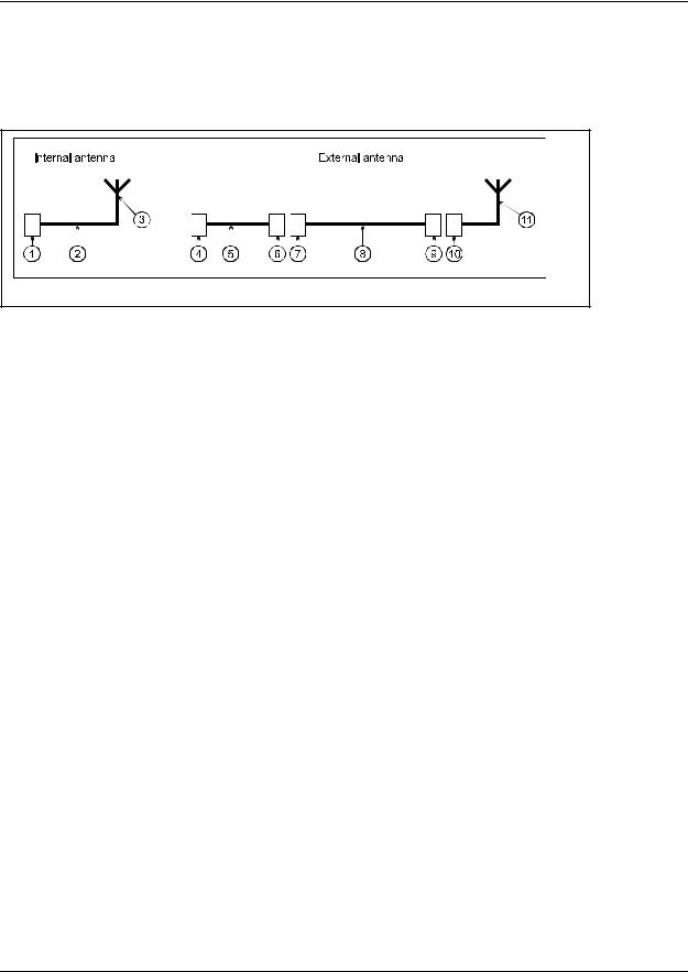
The MA431X23 and X24 antennas can be installed further from the base station. Ensure that the coaxial cables linking the antennas with the base stations provide low attenuation. The following figure illustrates two configurations:
Figure 4 Antenna configurations
•The internal antenna incorporates an MMS connector (1), one coaxial cable KX21 (2) and the radiating element (3). The antenna gain is 2 dBi.
•The external antenna is connected via a cord (4-5-6) which incorporates an MMS male connector (4), coaxial cable KX21 (5) and a TNC female connector (6). The manufacturer specifies losses of less than the guaranteed dB value. Losses are actually of the order of 0.7 dB at 2 GHz.
The extension cord conveying the signal to the antenna incorporates a TNC male connector (7), low loss coaxial RG58cu cable (8) and N male connector (9). The antenna (11) is secured to the extension cord using N female connector (10).
The losses generated by this extension cord are summarized in the following table.
Table 3 Generated losses with extension cord added
Element |
Losses at Frequency |
Estimated losses |
|
|
|
RG58cu |
0.65dB/m at 2GHz |
|
TNC |
0.2 dB at 9GHz |
0.1 dB |
N |
0.15 dB at 10GHz |
0.1 dB |
|
|
|
•The maximum length of the extension cord is 2.8 meters.
•The MA432X23 external antenna with an extension cord performs approximately in the same way as an internal antenna, except for the polarization diversity.
•The MA432X24 provides a 2 dB gain compared to the internal antenna.
P0606013 02
Chapter 1 DECT system overview and requirements 25
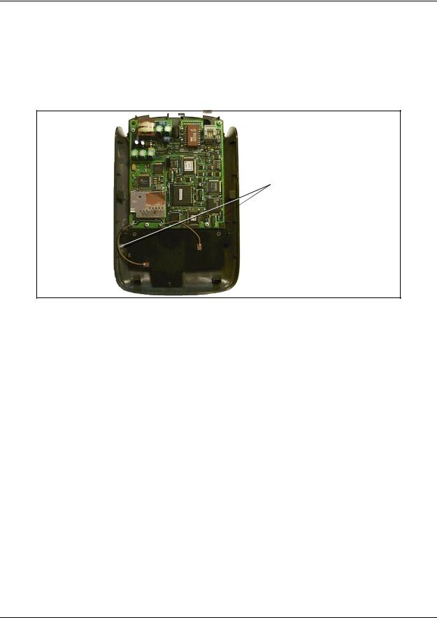
Specifications for DECT radio base stations
This section describes the radio base station specifications.
The following figure shows the base station with the top cover removed.
Figure 5 Inside the DECT radio base station
Internal antennas
The following specifications apply to DECT radio base stations:
frequency band: |
1880 -1900 MHz |
number of radio channels: |
8 |
transmission power: |
250 mw (peak)/10 mw (average) |
instantaneous throughput of the channel: |
1152 Kb/s |
signaling channel throughput (D channel between |
16 Kb/s |
the module and the base station): |
|
antenna type: |
omni-directional [one-way] or directional |
|
integrated or external antennas |
coverage range: |
from 10 to 30 metres (office environment), |
|
up to 300 metres (open air) |
radio base station operating temperature: |
+5 to +45 degrees Celsius |
number of simultaneous calls per radio base station: two or four |
|
base station synchronization: |
yes |
DECT Installation and Maintenance Guide

26 Chapter 1 DECT system overview and requirements
Base station notes:
Here are some general-information notes about the base station:
•Do not install more than two overlapping radio base stations per cell.
•Do not apply any paint or other wall covering to the plastic shell without written approval from Nortel Networks.
•Use the Unified Manager to perform resets of the base station.
•Signal processing functions for the four-channel radio base station are ported to the media bay module. In this case, the interface transports four 32 Kb/s ADPCM coded communications as well as 16 Kb/s signaling channel.
Climatic conditions
The DECT base station can tolerate the following conditions:
Operational:
• |
Temperature: |
5 to 45 degrees C. |
|
|
- 20 to +60 with a special cabinet |
• |
Relative humidity: |
10 to 80%, not condensing. |
Storage: |
|
|
• |
Temperature range: |
- 10 to 60 degrees C. |
•Relative humidity range: 10 to 90%, not condensing.
Power supply
The ISDN interface in the DECT media bay module enables the base stations to be powered through the cable connection between the DECT and the base station. The remote power supply is limited to 100 mA on the DECT interface, which corresponds to an available power of 4 W at 48V.
The radio base station can also be powered using a local a.c./d.c. mains power supply unit, PN 840 B. Use a local supply unit for no more than two radio base stations in any given cell.
Description of the connection
DECT base stations connect to DECT media bay modules using a cable containing two twisted pairs. This cable connects to RJ45 connectors on the components. The connection at the DECT position corresponds to an equipment number on the two cards on the DECT module that control the base station interaction. If you assign specific base stations to equipment numbers, you must ensure that base station is connected to the appropriate RJ45 jack on the DECT module.
P0606013 02

Chapter 1 DECT system overview and requirements 27
DECT cordless handsets
Check for small metal objects in the DECT Handset earpiece/mouthpiece before using the handset.
Do not store or locate flammable liquids, gases, or explosive materials in the same compartment or vicinity as the cordless handset, its parts or accessories.
This section describes the features provided by the C4010 and C4020 cordless handsets. These handsets were developed to work with DECT systems.
Other cordless handsets can be used with the DECT system. The system features available to other handsets depends on how the handset is configured, and how compatible it is with the signals transmitted from the DECT module. As well, some features such as call display also require the proper line configurations at both the local and telco end of the line.
Site configurations
Nortel Networks provides one PARI number on the DECT module that all the base stations share. Access is authorized by matching the PARI number and the PARK number registered in the Other multi-site configurations.
DECT call paths
The DECT module provides a telephony path separate from the Business Communication Manager system. This means there are three possible paths for a call to take.
•A DECT handset-to-handset call is routed from the calling handset, through the DECT module C8 interface, into the receiving handset.
•A DECT handset-to-Business Communications Manager set call is routed from the calling handset, into the C8 interface, and into the Business Communications Manager. The Business Communications Manager then routes the call through the appropriate station module to the receiving set.
•A DECT handset-to-external call is routed from the calling handset, into the C8 interface, and into the Business Communications Manager. The Business Communications Manager then routes the call through the appropriate trunk module out to the public network. This is the same route a call from a DECT handset to a set on a private network would use. The difference is that the user enters a different destination code.
•If a DECT handset transfers a call, the DECT C8 processes the transfer and creates a new call destination. The call remains routed through the C8 interface, even though the DECT handset is no longer involved in the call.
DECT Installation and Maintenance Guide
28 Chapter 1 DECT system overview and requirements
DECT programming overview
Here are some important points about using DECT on your Business Communications Manager.
•The Business Communications Manager must be configured with a region setting that provides DECT support.
Note: Valid DECT region settings:
Australia, Denmark, France, Germany, Global, Holland, Italy, Norway, Spain, Sweden,
Switzerland, Taiwan, United Kingdom
•The system default password is set to insta. You can delete or change this password to suit your needs.
•Default language is English.
•Disable the base stations before a firmware upgrade. Put the base stations back in service in sequence.
•To subscribe handsets, a base station must be set to accept handset recording.
•The handset DN must also be set into recording mode before the handset can be subscribed.
•The system uses data links.
•Within the DECT interface, numbers enclosed in ( ) indicate length of parameters. Refer also to “DECT interface commands” on page 28 and “Numbering plan syntax” on page 29.
Note: Refer to the Business Communications Manager Programming Operations Guide to configure telephony parameters for each handset DN.
DECT interface commands
The following table shows the main commands that are needed to navigate the DECT interface.
Table 4 DECT interface commands
Command |
Explanation |
|
|
Ctrl U |
Goes to main menu. |
|
|
Ctrl J |
Moves up one level of menus. |
space bar |
Toggles between items within screens. |
|
|
Esc (alpha commands) |
ESC M = more |
|
A list displays at the bottom of each screen. |
Del |
Deletes item backwards. |
|
|
Note: Data changes take effect immediately! There is no UNDO option.
P0606013 02

Chapter 1 DECT system overview and requirements 29
Numbering plan syntax
The following table explains how the syntax for the numbering plan works:
Table 5 Numbering plan syntax
Number Plan width |
Entry |
Means |
|
|
|
(2) |
1-2 |
10 to 29 |
(3) |
12-3 |
120 to 139 |
|
|
|
(5) |
1623-4 |
16230 to 16249 |
(5) |
1-2 |
10000 to 29999 |
|
|
|
Business Communications Manager requirements
The DECT system only works with a Business Communications Manager system that has been set to a compatible region. Region settings determine basic system compatibilities with local telephony protocols. Confirm the region on your Business Communications Manager before you attempt to install the system. Regions are discussed in the Business Communications Manager Programming Operations Guide.
This book describes the handset directory number (DN) system based on the default setup, where the Start DN is 221 and the DN length is three digits. If your system has a different DN structure, use the tables provided to translate the DNs listed to match those of your system.
Examples of DN structures:
If your Start DN is 221 but you require a five-digit DN, the system automatically creates a Start DN of 22221 when you specify a five-digit DN at startup.
If your Start DN needs to start with a specific number, change the Start DN after you specify the DN length at startup. For instance, if your Business Communications Manager is part of a CDP (Coordinated Dialing Plan) network with five-digit DNs, your system must have a unique first DN digit, so you would specify the exact Start DN, in this case, something like 31111.
DECT Installation and Maintenance Guide
30 Chapter 1 DECT system overview and requirements
Checking the System Region
If you experience problems configuring the DECT module on your system, check the region for which the system is set.
Note: DECT systems can be installed in countries that can run the following region profiles: UK, Australia, Sweden, Denmark, Holland, Norway, Italy, Germany, Spain, Switzerland, France, Global, Taiwan.
Refer to the Business Communications Manager Programming Operations Guide appendices for the table that lists all the regions.
Caution: You must select a region that reflects the geographical location of the Business Communications Manager.
If you choose the incorrect region, the Business Communications Manager system does not communicate correctly with the Public Switched Telephone Network.
This procedure describes how to ensure that the Business Communications Manager is set to the correct region for the DECT module.
1Open the Unified Manager for your Business Communications Manager system.
2On the navigation tree, click Diagnostics/MSC.
3On the top menu, click on Configuration.
4Click System startup.
5Ensure that the Region box displays the correct region.
Warning: If you reset the region profile on the Business Communications Manager, the system is reset to default parameters. Therefore, ensure that you have a current backup before you attempt to do this procedure.
Note: When you select a new region, the Template box is disabled. You must restart the system before the templates for the selected region are available.
aTo change the region, select a region from the list.
bClick OK to apply these changes.
The system displays a warning that the system will restart and that the default programming values will be restored.
cClick Cold Start to restart the Unified Manager.
6 Continue with the DECT deployment.
P0606013 02
Loading...