


 Loading...
Nortel Business Communications Manager 450 1.0
Installation—Devices
Release: 1.0
Document Revision: 01.01
NN40160-302
Document status: Standard
Document issue: 01.01
Document date: August 2008
Product release: BCM450 1.0
Job function: Installation
Type: Technical Publication
Language type: English
Copyright © 2008 Nortel Networks.
All Rights Reserved.
NORTEL, the globemark design, and the NORTEL corporate logo are trademarks of Nortel Networks.

Contents
|
|
New in this release |
|
|
|
|
7 |
||
|
|
Features 7 |
|
|
|
|
|
|
|
|
|
|
|
|
|
|
|
|
|
|
|
Introduction |
|
|
|
|
9 |
||
|
|
|
|
|
|||||
|
|
Overview of key hardware elements and devices |
11 |
|
|||||
|
|
BCM450 main and expansion units |
11 |
|
|
|
|||
|
|
Media bay module types |
12 |
|
|
|
|
|
|
|
|
BCM450 features 12 |
|
|
|
|
|
|
|
|
|
BCM450 applications 12 |
|
|
|
|
|
||
|
|
Digital devices |
13 |
|
|
|
|
|
|
|
|
Navigation |
13 |
|
|
|
|
|
|
|
|
Corded display sets and options |
13 |
|
|
|
|||
|
|
Cordless sets and options |
13 |
|
|
|
|
||
|
|
Key indicator module |
13 |
|
|
|
|
|
|
|
|
BST Doorphone 14 |
|
|
|
|
|
|
|
|
|
Central Answering Position 14 |
|
|
|
|
|||
|
|
Wireless devices 14 |
|
|
|
|
|
|
|
|
|
DECT 4xxx series handsets |
14 |
|
|
|
|
||
|
|
Digital mobility phones |
14 |
|
|
|
|
|
|
|
|
WLAN handsets 221X 14 |
|
|
|
|
|
||
|
|
WLAN Handsets 6120 and 6140 15 |
|
|
|
||||
|
|
IP devices 15 |
|
|
|
|
|
|
|
|
|
Navigation |
15 |
|
|
|
|
|
|
|
|
IP phone registration |
15 |
|
|
|
|
|
|
|
|
IP phone configuration |
16 |
|
|
|
|
|
|
|
|
Registering the telephone to the system 17 |
|
|
|
||||
|
|
Configuring telephone settings |
17 |
|
|
|
|||
|
|
Troubleshooting IP telephones 19 |
|
|
|
||||
|
|
1100 series IP phones |
20 |
|
|
|
|
|
|
|
|
Expansion module for 1100 series IP phones |
20 |
|
|
||||
|
|
1200 series IP phones |
20 |
|
|
|
|
|
|
|
|
Expansion module for 1200 series IP phones |
20 |
|
|
||||
|
|
2000 series IP phones |
21 |
|
|
|
|
|
|
|
|
|
|
|
|||||
|
|
Nortel Business Communications Manager 450 1.0 |
|
|
|||||
|
|
|
Installation—Devices |
|
|
|
|||
|
|
|
NN40160-302 |
01.01 Standard |
|
|
|
||
August 2008
Copyright © 2008, Nortel Networks

4 Contents
IP Key Expansion Module 21
IP Softphone 2050 21
IP Audio Conference Phone 2033 22
Analog devices 22
Analog station media bay module 22
Analog terminal adapter 23
Device compatibility and installation requirements |
25 |
|||
Release compatibility 25 |
|
|
|
|
Release compatibility navigation 25 |
|
|
||
ISDN basics 25 |
|
|
|
|
Services and features for ISDN BRI and PRI |
27 |
|
||
ISDN hardware |
32 |
|
|
|
ISDN standards compatibility 35 |
|
|
||
Plan your Integrated Services Digital Network |
35 |
|
||
Order ISDN PRI |
35 |
|
|
|
Order ISDN BRI |
36 |
|
|
|
Supported ISDN protocols 37 |
|
|
||
MBM trunk requirements |
37 |
|
|
|
MBM station requirements |
38 |
|
|
|
IP phones and IP telephony |
|
41 |
||
IP phone Basics 41 |
|
|
|
|
IP telephones and VoIP trunks 42 |
|
|
||
IP telephones 42 |
|
|
|
|
Voice over IP trunks |
43 |
|
|
|
IP telephony networking |
43 |
|
|
|
BCM networking 44 |
|
|
|
|
Meridian 1 Internet Telephony Path |
44 |
|
||
Telephone interoperability |
45 |
|
|
|
Network gatekeepers |
45 |
|
|
|
Public Switched Telephone Network |
46 |
|
||
Key IP telephony concepts |
46 |
|
|
|
Codecs 47 |
|
|
|
|
Jitter buffer 47 |
|
|
|
|
Quality of service routing |
48 |
|
|
|
Telephone relocation 49 |
|
|
|
|
Digital telephone relocation 49 |
|
|
||
Digital telephone relocation recommendations |
|
|||
49 |
|
|
|
|
IP telephones relocation |
49 |
|
|
|
|
|
|||
Media bay module configuration |
51 |
|||
Configuring resources for the MBM 51 |
|
|
||
Nortel Business Communications Manager 450 1.0
Installation—Devices
NN40160-302 01.01 Standard
August 2008
Copyright © 2008, Nortel Networks

|
|
Contents 5 |
|
|
|
|
IP phone registration |
53 |
|
Enabling registration in Element Manager 53 |
|
|
Automatically assign directory names |
54 |
|
Registering IP phones in the system |
55 |
Accessing the local configuration menu on an IP Phone 2001, 2002 or 2004 55
Accessing the local configuration menu on an IP Phone 2033 |
56 |
Accessing the local configuration menu on an IP Phone 2007 |
56 |
Accessing configuration menu on an IP Phone 1120E or 1140E 57 |
|
Accessing configuration menu on an IP Phone 1210, 1220, or 1230 58 |
|
Deregistering IP telephones 58 |
|
IP Phone 1120E or IP Phone 1140E configuration |
61 |
|||||||
Opening the network configuration menu 63 |
|
|||||||
Setting 802.1x authentication |
64 |
|
|
|||||
Setting DHCP |
65 |
|
|
|
|
|
|
|
Setting the IP address |
65 |
|
|
|
||||
Setting the gateway |
66 |
|
|
|
|
|||
Setting S1 IP |
66 |
|
|
|
|
|
|
|
Setting S1 port |
67 |
|
|
|
|
|
|
|
Setting S1 action |
67 |
|
|
|
|
|
||
Setting S1 retry |
68 |
|
|
|
|
|
|
|
Setting S1 private key |
68 |
|
|
|
||||
Setting S2 IP |
69 |
|
|
|
|
|
|
|
Setting S2 port |
70 |
|
|
|
|
|
|
|
Setting S2 action |
70 |
|
|
|
|
|
||
Setting S2 retry |
71 |
|
|
|
|
|
|
|
Setting S2 private key |
71 |
|
|
|
||||
Setting VLAN |
72 |
|
|
|
|
|
|
|
Setting the VLAN filter |
73 |
|
|
|
||||
Setting the PC port |
73 |
|
|
|
|
|
||
Setting data VLAN |
74 |
|
|
|
|
|
||
Setting PC_Port Untag All |
74 |
|
|
|||||
Setting the duplex mode |
75 |
|
|
|
||||
Setting Gratuitous ARP |
76 |
|
|
|
||||
Setting External Application Server |
76 |
|
||||||
Setting the XAS port 77 |
|
|
|
|
||||
Upgrading the IP phone firmware |
78 |
|
||||||
|
|
|
|
|||||
Telephone relocation |
|
|
79 |
|||||
Digital telephone relocation |
79 |
|
|
|||||
Keeping an IP telephone active 79
IP telephone relocation without changing the DN 80
IP telephone relocation with a changed DN 80
Nortel Business Communications Manager 450 1.0
Installation—Devices
NN40160-302 01.01 Standard
August 2008
Copyright © 2008, Nortel Networks

6 Contents
Media encryption on IP phones |
83 |
|
Configuring SRTP media encryption on a Phase II IP Phone 2001, 2002, and |
|
|
2004 |
83 |
|
Configuring SRTP media encryption on an IP Phone 2007 84 |
|
|
Configuring SRTP media encryption on an IP Phone 1110, 1120E, and 1140E |
85 |
|
Configuring SRTP media encryption on an IP Phone 1210, 1220, and 1230 85 |
|
|
|
|
|
Device Compatibility |
87 |
|
|
|
|
IP Phones reference |
89 |
|
Nortel Business Communications Manager 450 1.0
Installation—Devices
NN40160-302 01.01 Standard
August 2008
Copyright © 2008, Nortel Networks

New in this release
This is the initial release of the BCM450 platform. This document contains information about devices supported by the BCM450 system in Release 1.0.
Features
See the following sections for information found in this guide.
•The Overview of key hardware elements and devices section includes information about BCM450 media bay modules, applications, digital devices, IP devices and wireless devices.
•The Device compatibility and installation requirements section includes information about using Integrated Services Digital Network (ISDN) lines on your BCM450 system.
•The IP phones and IP telephony section includes an overview of the components that comprise the BCM450 IP telephony and Voice over IP (VoIP) features
•The Media bay module configuration section includes information about installing MBMs.
•The IP phone registration section includes information about registering your IP phone.
•The IP Phone 1120E or IP Phone 1140E configuration section includes procedures about configuring your IP Phone 1120E or 1140E.
•The Telephone relocation section includes procedures about moving a telephone within the system so that the telephone programming follows the telephone to the new location.
•The Media encryption on IP phones section includes procedures about enabling media encryption on your IP phone.
Nortel Business Communications Manager 450 1.0
Installation—Devices
NN40160-302 01.01 Standard
August 2008
Copyright © 2008, Nortel Networks

8 New in this release
Nortel Business Communications Manager 450 1.0
Installation—Devices
NN40160-302 01.01 Standard
August 2008
Copyright © 2008, Nortel Networks

Introduction
This document contains conceptual, task-based, and reference information about analog, digital, IP, and Integrated Services Digital Network (ISDN) devices on a Business Communications Manager 450 (BCM) system.
The information in this guide explains how to
•install and configure components
•register and relocate telephones and devices
•enable media encryption
Use Element Manager, Startup Profile, and Telset Administration to configure BCM450 parameters.
Navigation
•Overview of key hardware elements and devices (page 11)
•Device compatibility and installation requirements (page 25)
•IP phones and IP telephony (page 41)
•Media bay module configuration (page 51)
•IP phone registration (page 53)
•IP Phone 1120E or IP Phone 1140E configuration (page 61)
•Telephone relocation (page 79)
•Media encryption on IP phones (page 83)
•Device Compatibility (page 87)
•IP Phones reference (page 89)
Nortel Business Communications Manager 450 1.0
Installation—Devices
NN40160-302 01.01 Standard
August 2008
Copyright © 2008, Nortel Networks

10 Introduction
Nortel Business Communications Manager 450 1.0
Installation—Devices
NN40160-302 01.01 Standard
August 2008
Copyright © 2008, Nortel Networks
Overview of key hardware elements and devices
The Business Communications Manager 450 system provides private network and telephony management capability to small and medium-sized businesses.
The BCM450 system
•integrates voice and data capabilities, Voice over Internet Protocol (VoIP) gateway functions, and Quality of Service (QoS) data-routing features into a single telephony system
•enables you to create and provide telephony applications for use in a business environment
This section describes the telephony devices BCM450 supports.
Navigation
•BCM450 main and expansion units (page 11)
•Media bay module types (page 12)
•BCM450 features (page 12)
•BCM450 applications (page 12)
•Digital devices (page 13)
•Wireless devices (page 14)
•IP devices (page 15)
•Analog devices (page 22)
•Analog terminal adapter (page 23)
BCM450 main and expansion units
BCM450 includes the following key elements:
•BCM450 main unit
•BCM450 expansion unit
Nortel Business Communications Manager 450 1.0
Installation—Devices
NN40160-302 01.01 Standard
August 2008
Copyright © 2008, Nortel Networks

12 Overview of key hardware elements and devices
Media bay module types
BCM450 includes the following media bay modules (MBM):
•4 x 16
•ADID4
•ADID8
•ASM8, ASM8+
•BRIM
•CTM4, CTM8
•DSM16, DSM32
•DSM16+, DSM32+
•DTM
•FEM
•GASM
•GATM4, GATM8
•G4 x 16
•G8 x 16
•R2MFC
BCM450 features
BCM450 supports the complete range of IP telephony features offered by existing BCM products.
BCM450 applications
BCM450 supports many applications provided on the existing BCM platform.
Enter the appropriate keycodes to enable the following features (no additional hardware required):
•Voice Messaging for standard voice mail and auto-attendant features
•Unified Messaging to provide integrated voice mail management between voice mail and common e-mail applications
•Fax Suite to providing support for attached analog fax devices
•Voice networking features
•LAN CTE (computer telephony engine)
•VEWAN
•IP Music
Nortel Business Communications Manager 450 1.0
Installation—Devices
NN40160-302 01.01 Standard
August 2008
Copyright © 2008, Nortel Networks

Overview of key hardware elements and devices 13
•Contact Center
Digital devices
BCM450 supports corded display sets, cordless sets, key indicator modules (KIM), the Business Series Terminal (BST) Doorphone, and the Central Answering Position.
Navigation
•Corded display sets and options (page 13)
•Cordless sets and options (page 13)
•Key indicator module (page 13)
•BST Doorphone (page 14)
Corded display sets and options
•T7000 (International only): four memory buttons, without display or indicators.
•T7100: one-line display, and one memory button without indicator.
•T7208: one-line display, and eight memory buttons with indicators.
•T7316: two-line display, three display buttons, 16 memory buttons with indicators, and eight memory buttons without indicators. The T7316 supports separate mute key and a headset key under the dial pad.
T7316E: two-line display, three display buttons, 16 memory buttons with indicators, and eight memory buttons without indicators; handsfree, mute, and headset buttons (under the dial pad).
Cordless sets and options
•T7406 cordless telephone system: six memory buttons with indicators and a two-line display with three display buttons. The T7406 provides cordless mobility in a small office environment. Each base station supports three telephones. Function is based on the 7316 telephone. The base station connects to a digital station media bay module on the system.
•T7406E cordless handset: six memory buttons with indicators and a three-line display with three display buttons. The T7406E provides cordless mobility in a small office environment. Each base station supports four handsets. The base station connects to a digital station media bay module on the system.
Key indicator module
The KIM includes 24 memory buttons with indicators.
Nortel Business Communications Manager 450 1.0
Installation—Devices
NN40160-302 01.01 Standard
August 2008
Copyright © 2008, Nortel Networks

14 Overview of key hardware elements and devices
BST Doorphone
Use BST Doorphone as an intercom to control access to your building. Press the Call button on the BST Doorphone to call one or more telephones, or send a distinctive chime to telephones in an assigned page zone. Place an internal call from any telephone on the system to the BST Doorphone to set up a twoway voice call. Install a Door Opening Controller to permit the activation of locks on doors or gates.
Central Answering Position
Central Answering Position (CAP/eCAP) provides additional auto dial positions or additional line appearances. The CAP consists of a T7316E telephone and from one to nine KIMs.
Wireless devices
BCM450 supports Digital Enhanced Cordless Telecommunications (DECT) handsets, digital mobility phones, and WLAN handsets.
DECT 4xxx series handsets
•DECT 413x series handsets: three display soft keys, four-line handset display, and text messaging.
•DECT 414x series handsets: three display soft keys, four-line handset display, loudspeaker capability, and text messaging.
Digital mobility phones
•Digital Mobility Phone 7420: three display soft keys, four-line handset display.
•Digital Mobility Phone 7430: three display soft keys, and four-line handset display, text messaging.
•Digital Mobility Phone 7440: three display soft keys, and four-line handset display, loudspeaker capability, and text messaging.
WLAN handsets 221X
WLAN handsets use VoIP technology and Push-to-Talk, which enables twoway communication with another BCM user.
The handsets communicate with the BCM system and with the WLAN IP Telephony Manager 2245. Like wired telephones, the wireless handsets receive calls directly, receive transferred calls, transfer calls to other extensions, and make outside and long-distance calls (subject to corporate restrictions). The handsets interoperate with other IP Line and IP Trunk features and devices, such as IP Peer, and the IP Phone 20xx and IP Softphone 2050 series of IP Phones.
Nortel Business Communications Manager 450 1.0
Installation—Devices
NN40160-302 01.01 Standard
August 2008
Copyright © 2008, Nortel Networks

Overview of key hardware elements and devices 15
WLAN Handsets 6120 and 6140
The WLAN Handsets 6120 and 6140 operate with the BCM and the WLAN IP Telephony Manager 2245. They are fully functional handsets specifically designed for the busy office environment. The WLAN Handsets 6120 and 6140 use radio wave technology to send and receive voice and data transmissions. They operate much like a cell phone. However, the Handsets use the private communication system installed in your facility and will not operate outside the area covered by this system.
IP devices
BCM450 supports IP phones, IP phone expansion modules, a softphone, and an audio conference phone.
Navigation
•IP phone registration (page 15)
•IP phone configuration (page 16)
•Registering the telephone to the system (page 17)
•Configuring telephone settings (page 17)
•Troubleshooting IP telephones (page 19)
•1100 series IP phones (page 20)
•Expansion module for 1100 series IP phones (page 20)
•1200 series IP phones (page 20)
•Expansion module for 1200 series IP phones (page 20)
•2000 series IP phones (page 21)
•IP Key Expansion Module (page 21)
•IP Softphone 2050 (page 21)
•IP Audio Conference Phone 2033 (page 22)
IP phone registration
Registering IP telephones to the system is a two-stage process.
•Set up the system programming to receive registration under Resources > Telephony Resources. For more information see, IP phone registration (page 53)
•Configure each telephone.
When the telephone registers, it downloads the information from the system IP Telephony record to the telephone configuration record. This can include a new firmware download, which occurs automatically. If new firmware downloads, the telephone display indicates the event.
Nortel Business Communications Manager 450 1.0
Installation—Devices
NN40160-302 01.01 Standard
August 2008
Copyright © 2008, Nortel Networks

16 Overview of key hardware elements and devices
Attention: If the telephone displays a prompt that indicates it cannot find the server, follow the instructions in IP phone registration (page 53) to enter the specific network path. Troubleshooting IP telephones (page 19) describes other possible prompt messages.
If you do not automatically register to the system, you can configure the telephone settings to enable you to access a system on the network. You must perform additional steps if your IP telephone does not connect to the same LAN to which the system connects.
After you have entered all the configuration information, the telephone attempts to connect to the system. The message “Locating Server” appears on the display. If the connection is successful, the message changes to “Connecting to Server” after 15 seconds. Initialization can take several minutes. Do not disturb the telephone during this time.
When the telephone connects to the server and is ready to use, the display shows the time and date, and the six keys at the top of the display become labelled.
If you experience problems with IP telephone registration, see
Troubleshooting IP telephones (page 19).
If the DN record is not configured, as with auto-assigned DNs, you can only place local calls until other lines assigned in the DN record.
If no one registered the telephone previously, you receive a “New Set” message. Enter the information as prompted. See Registering the telephone to the system (page 17).
IP phone configuration
The configuration of the IP phones depends on whether you use Dynamic Host Control Protocol (DHCP) on the system.
•If you use DHCP service on the system, or you configured the Customer DHCP server to hand out specific system network details, the IP telephone automatically attempts to find the server.
After you register the telephone to the system, as described in, Registering the telephone to the system (page 17)the telephone assumes the parameters it receives from the system, which are described in Configuring telephone settings (page 17)
•If you did not configure DHCP to provide system information, or if you do not use DHCP on your network, you must configure your telephone parameters before the telephone can register to the system. In this case, follow the directions in Configuring telephone settings (page 17), and then
Nortel Business Communications Manager 450 1.0
Installation—Devices
NN40160-302 01.01 Standard
August 2008
Copyright © 2008, Nortel Networks

Overview of key hardware elements and devices 17
follow the prompts that appear, as described in Registering the telephone to the system (page 17)
•If an external DHCP server does not exist, the DHCP server on the main unit supplies IP configuration information for all IP devices (PCs and IP Phones). It also supplies specific connection information to the IP Phones.
Registering the telephone to the system
When you first connect the telephone to the IP connection, you receive one of the following:
•If the telephone is not yet registered, and when a password is entered in the Terminal Registration screen, the telephone prompts you for that password.
•If Auto Assign DN is not selected, the telephone prompts you for a DN. For more information see the BCM450 1.0 Configuration–Devices Guide
(NN40160-500)
•If you are prompted for a password, enter the password and press OK.
•If you are prompted for a DN, enter the DN you want assigned to this telephone and press OK.
When the telephone registers, it downloads the information from the system IP Telephony record to the telephone configuration record. This can include a new firmware download, which occurs automatically. If new firmware downloads, the telephone display indicates the event.
If the telephone displays a prompt that indicates it cannot find the server, follow the instructions in Configuring telephone settings (page 17)to enter the specific network path.Troubleshooting IP telephones (page 19) describes other possible prompt messages.
Configuring telephone settings
If you are not automatically registered to the system, you can configure the telephone settings to enable you to access a system on the network. You also must perform these steps if your IP telephone is not connected to the same LAN to which the system is connected. For more information about accessing the telephone configuration menus see, IP phone registration (page 53)
If you experience problems with IP telephone registration, refer to the section Troubleshooting IP telephones (page 19).
If the DN record is not configured yet, as is the case with auto-assigned DNs, you can only place local calls until other lines are assigned in the DN record. If the telephone has not been registered before, you receive a New Set message. Enter the information, as prompted. The following table describes the values for each display parameter. For more information see, Registering the telephone to the system (page 17)
Nortel Business Communications Manager 450 1.0
Installation—Devices
NN40160-302 01.01 Standard
August 2008
Copyright © 2008, Nortel Networks

18 Overview of key hardware elements and devices
Table 1 IP telephone server configurations
Field |
Value |
Description |
|
|
|
DHCP |
0 or 1 |
Enter 0 if your network does not use a DHCP server to |
|
|
dispense IP addresses. (Static DHCP) |
|
|
Enter 1 if your network uses a DHCP server. |
|
|
|
If DHCP = 0 |
|
|
|
|
|
SET IP |
<IP address> |
The set IP must be a valid and unused IP address on the |
|
|
network to which the telephone connects. |
NETMASK |
<subnet mask |
This is the subnet mask. This setting is critical for locating |
|
address> |
the system to which you want to connect. |
DEF GW |
<IP address> |
Default Gateway on the network (for example, the nearest |
|
|
router to the telephone. The router for IP address W.X.Y.Z |
|
|
is usually at W.X.Y.1). |
|
|
If there are no routers between the telephone and the |
|
|
system network adaptor to which it connects, (for |
|
|
example, a direct HUB connection), enter the Published |
|
|
IP address of the BCM450 as the DEF GW. |
|
|
If the IP telephone does not connect directly to the |
|
|
Published IP address network adapter, set the DEF GW |
|
|
to the IP address of the network adaptor to which the |
|
|
telephone connects. |
Emulation Key |
0 or 1 |
0 = Handset |
Mapping |
|
1= Handsfree |
|
|
|
|
|
Default setting is 1 (handsfree)—do not change. |
|
|
This setting applies to the 2033 model only. |
|
|
|
If DHCP = 1 |
|
|
|
|
|
Manual Cfg? |
Full = 0 |
If you indicate DHCP for the telephone, but you want to |
DHCP: |
Partial = 1 |
enter static IP addresses, choose 1 (Partial). |
|
||
|
|
If you choose 0 (Full), the DHCP server assigns IP |
|
|
addresses that are not static. |
|
|
|
If DHCP = 0 or Partial |
|
|
|
|
|
S1 IP |
<IP address> |
This is the Published IP address of the first BCM system |
|
|
to which you want to register the telephone. |
S1 PORT |
Default: *7000 |
This is the port the telephone uses to access this system. |
S1 ACTION |
Default: 1 |
|
S1 RETRY |
<digits between |
Configure this to the number of times you want the |
COUNT |
0 |
telephone to retry the connection to the system. |
and 255>
Nortel Business Communications Manager 450 1.0
Installation—Devices
NN40160-302 01.01 Standard
August 2008
Copyright © 2008, Nortel Networks

|
|
Overview of key hardware elements and devices 19 |
|
Table 1 IP telephone server configurations |
|||
|
|
|
|
Field |
Value |
Description |
|
|
|
|
|
S2 IP |
<IP address> |
This is the Published IP address of the second BCM |
|
|
|
system to which you want to register the telephone. It can |
|
|
|
match the S1 setting. |
|
S2 PORT |
Default: *7000 |
This is the port the telephone uses to access this system. |
|
S2 ACTION |
Default: 1 |
|
|
S2 RETRY |
<digits between |
Set this to the number of times you want the telephone to |
|
COUNT |
0 |
retry the connection to the system. |
|
|
and 255> |
|
|
VLAN |
0: No VLAN |
Choose 0: NO VLAN if no VLAN exists on the network. |
|
|
1: Manual VLAN |
If DHCP does not exist on the network, or if a remote |
|
|
2: Automatically |
server supplies DHCP, select number 1 and enter the |
|
|
VLAN ID (see Note 1). |
||
|
discover VLAN |
If you have the system DHCP active on your system, |
|
|
|
||
|
using DHCP |
select 2 if you want DHCP to find the VLAN assignment |
|
|
|
automatically. |
|
|
|
VLAN is a network routing feature provided by specific |
|
|
|
types of switches. To find out if your system uses VLAN, |
|
|
|
check with your network administrator. If your system |
|
|
|
uses VLAN, the system administrator responsible for the |
|
|
|
switch can provide the VLAN IDs for your system (see |
|
|
|
Note 1). |
|
Cfg XAS? |
0: No (default) |
If you want to enable connection to a Net6 service |
|
|
1: Yes |
provider server, choose 1. The system prompts you for an |
|
|
IP address for the server. |
||
|
|
||
Note 1: Ensure that the firewall filters are set up to allow IP traffic into and out of the system.
Troubleshooting IP telephones
If the system is not properly configured, several messages can appear.
Table 2 IP telephony display messages
|
Message |
Description/Solution |
|
|
|
|
|
|
SERVER: NO PORTS LEFT |
The system has run out of ports. This message remains on the |
|
|
|
display until a port becomes available and the telephone is |
|
|
|
powered down and then up. To obtain more ports, you can install |
|
|
|
additional VoIP keycodes. |
|
|
INVALID SERVER ADDRESS |
The S1 is incorrectly configured with the IP address of a system |
|
|
|
network adapter other than the published IP address. |
|
|
IP ADDRESS CONFLICT |
The telephone detected that a device on the network is currently |
|
|
|
using the IP address allocated to the telephone. |
|
|
|
|
|
|
|
|
|
Nortel Business Communications Manager 450 1.0
Installation—Devices
NN40160-302 01.01 Standard
August 2008
Copyright © 2008, Nortel Networks

20 Overview of key hardware elements and devices
Table 2 IP telephony display messages
Message |
Description/Solution |
|
|
|
|
REGISTRATION DISABLED |
The Registration on the system is set to OFF. |
|
SERVER UNREACHABLE. |
Check that you have entered the correct Netmask and gateway |
|
RESTARTING . . . |
IP addresses. If the settings are correct, contact your system |
|
administrator. |
||
|
||
NEW SET |
The telephone has not been connected to the system before, and |
|
|
must be registered. |
|
|
|
1100 series IP phones
BCM450 supports 1100 series IP phones.T The IP Phone 1110, 1120E, and 1140E. The three phones in the series have a graphical high-resolution LCD display, backlit, with adjustable contrast.
•IP Phone 1110has three user-defined feature keys and four soft keys.
•IP Phone 1120Ehas four user-defined feature keys and four soft keys.The IP Phone 1120 brings voice and data to the desktop by connecting directly to a local area network (LAN) though an Ethernet connection.
•IP Phone 1140Ehas six user defined feature keys and four soft keys through an Ethernet connection.The IP Phone 1140 brings voice and data to the desktop by connecting directly to a LAN ISDN devices.
Expansion module for 1100 series IP phones
Compatible with the IP Phone 1120E and 1140E, the expansion module includes 18 self-labelling keys. You can connect up to three modules to a phone for a maximum of 54 additional line or feature keys.
1200 series IP phones
The IP Phones 1210, 1220, and 1230 bring voice and data to the desktop by connecting directly to a local area network (LAN) through an Ethernet connection. Programmable button labels appear beside the keys, and soft key labels appear directly above the keys.
The keys on either side of the navigation keys are programmable keys. The IP Phone 1210 has two keys, while the IP Phone 1220 and 1230 have six keys. The system administrator programs these keys.
Expansion module for 1200 series IP phones
Two expansion module models exist for the IP Phone 1200 series of phones:
•The Expansion Module for IP Phone 1200 series with display.
•The Expansion Module for IP Phone 1200 series with paper label.
Nortel Business Communications Manager 450 1.0
Installation—Devices
NN40160-302 01.01 Standard
August 2008
Copyright © 2008, Nortel Networks
Overview of key hardware elements and devices 21
The expansion modules for IP Phone 1200 series are hardware accessories that connect to the IP Phone and provide additional line appearances and feature keys.
The expansion modules provide either 12 or 18 additional line or programmable feature keys for your IP Phone. An IP Phone supports up to seven Expansion Modules for IP Phone 1200 Series with display or up to two Expansion Modules for IP Phone 1200 Series with paper labels. An IP phone does not support two different expansion module types on the same phone.
2000 series IP phones
BCM450 supports
IP Phone 2001: connects through an IP link to the BCM450 system. The IP Phone 2001 has a single-line text display with a row of display keys on the second display line. The IP Phone 2001 can be used to call through any type of BCM450 line.
IP Phone 2002: connects through an IP link to the BCM450 system. The IP Phone 2002 has a two-line text display with a row of display keys on the third display line, and four memory keys with indicators. The IP Phone 2002 can be used to call through any type of BCM450 line.
IP Phone 2004: connects through an IP link to the BCM450 system. The IP Phone 2004 has a six-line text display with a row of display keys on the eighth display line, and six memory keys with indicators. The IP Phone 2004 can be used to call through any type of BCM450 line.
IP Phone 2007: connects to a LAN through an Ethernet connection. The IP Phone 2007 supports call processing features, and can work with an External Application Server to display web-based and interactive applications on the large, color LCD touch screen.
IP Key Expansion Module
The IP Key Expansion Module (KEM) can have up to 24 programmable keys (with labels) for IP Phone 2002 or 2004 models with a maximum of four IP KEMs for one phone.
IP Softphone 2050
The IP Softphone 2050 provides VoIP services using a telephony server and your company local area network (LAN). The IP Softphone 2050 includes oneclick direct dialing from various windows and applications, twelve user defined feature keys, and four soft keys.
Nortel Business Communications Manager 450 1.0
Installation—Devices
NN40160-302 01.01 Standard
August 2008
Copyright © 2008, Nortel Networks

22 Overview of key hardware elements and devices
IP Audio Conference Phone 2033
The IP Audio Conference Phone 2033 provides audio conferencing with a keypad that provides many of the set features of the basic Business Series telephones without display or memory buttons. The audio conference phone includes three microphones, and installation instructions.
Analog devices
BCM450 supports analog telephones (single-line telephones), cordless telephones, fax machines, answering machines, and modems (with a maximum speed of 28.8 kbit/s).
You must install an analog station media bay module (ASM8, ASM8+, or GASM) for analog devices (see Analog station media bay module (page 22)). To connect a standard analog voice device or data communication device to the BCM system through a digital station module, you must install an ATA2 (see Analog terminal adapter (page 23)).
Analog station media bay module
You can connect a maximum of eight analog telecommunication devices to the analog station media bay modules (ASM8, ASM8+, and GASM). Analog devices include standard analog telephones, cordless telephones, fax machines, answering machines, or modems. The maximum speed for a modem connection is 28.8 kbit/s.
The ASM8 is available in North America only; the ASM8+ and GASM8 are available in North America, the United Kingdom, Australia, and Poland.
In addition to ASM8 features, the ASM8+ and GASM offer the following features:
•Visual Message Waiting Indicator (VMWI) LED indicates to the end user that a message is waiting.
•Disconnect supervision (Open Switch Interval [OSI] according to EIA/TIA 464) indicates to the attached device, in an established communication, that the connected device must release the call.
Attention: When disconnect occurs from the central office (CO), the ASM8+ provides an OSI 850 ms (TIA/EIA 464 section 5.4.10.2.4; minimum is 600 ms) to the off-hook station of as a disconnect signal. If the station remains on-hook after the disconnect signal, the ASM8+ disconnects the station equipment from the network without returning a tone (TIA/EIA 464 section 5.4.10.2.5[1]). After the station equipment goes on-hook, the ASM8+ station interface restores to on-hook (idle). You must ensure that the device, application, or interface card connected to an ASM8+ station interface conform to these on-hook and off-hook conditions.
Nortel Business Communications Manager 450 1.0
Installation—Devices
NN40160-302 01.01 Standard
August 2008
Copyright © 2008, Nortel Networks
Overview of key hardware elements and devices 23
•Caller ID provides the name, phone number, and other information about the caller to the end user at the start of the call.
•Firmware downloading capability allows the system to upgrade the ASM8+ and GASM firmware at customer sites.
•Enhanced ringing capability ASM8+ and GASM provide a ringing voltage of two REN/65 V rms per port.
•GASM8 is designated as an on-premise station (OPS) port.
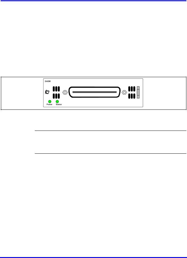
The ASM8, ASM8+, and GASM each have one RJ-21 connector on the faceplate.
Figure 1 GASM faceplate LEDs and connectors
The ringer equivalency number (REN) per port for ASM8 is 1; the REN for ASM8+ and GASM is 2.
Attention: The termination of the analog interface can consist of any combination of devices, subject only to the requirement that the sum of the RENs of all the devices does not exceed the REN of the interface to which the device is connected.
Analog terminal adapter
The analog terminal adapter 2 (ATA2) or ATA connects a standard analog voice device or data communication device to the BCM450 system through a digital station module. Examples of analog voice devices include analog telephones and answering machines. Examples of analog data communication devices include modems and fax machines.
The ATA2 provides on-premise service only (protected plan wiring only).
The following figure shows an installation overview for connecting an analog device or analog data device through an ATA2 to the BCM450 main unit.
Nortel Business Communications Manager 450 1.0
Installation—Devices
NN40160-302 01.01 Standard
August 2008
Copyright © 2008, Nortel Networks

24 Overview of key hardware elements and devices
Figure 2 Analog device installation overview
Nortel Business Communications Manager 450 1.0
Installation—Devices
NN40160-302 01.01 Standard
August 2008
Copyright © 2008, Nortel Networks

Device compatibility and installation requirements
This section provides general information about using Integrated Services Digital Network (ISDN) lines on your Business Communications Manager 450 (BCM) system. You can access detailed information about ISDN through the internet. Your service provider can also provide you with specific information to help you understand what suits your requirements.
Navigation
•Release compatibility (page 25)
•MBM trunk requirements (page 37)
•MBM station requirements (page 38)
Release compatibility
Refer to the following topics for release compatibility information:
Release compatibility navigation
•ISDN basics (page 25)
•Services and features for ISDN BRI and PRI (page 27)
•ISDN hardware (page 32)
•ISDN standards compatibility (page 35)
•Plan your Integrated Services Digital Network (page 35)
•Order ISDN PRI (page 35)
•Order ISDN BRI (page 36)
•Supported ISDN protocols (page 37)
ISDN basics
ISDN technology provides a fast, accurate, and reliable means to send and receive voice, data, images, text, and other information through the telecom network.
Nortel Business Communications Manager 450 1.0
Installation—Devices
NN40160-302 01.01 Standard
August 2008
Copyright © 2008, Nortel Networks

26 Device compatibility and installation requirements
ISDN uses existing analog telephone wires to multiplex data into separate digital channels, which increases bandwidth.
ISDN uses a single transport to carry multiple information types. Where you once required separate networks for voice, data, images, or video conferencing, it now combines into one common high-speed transport.
Analog versus ISDN
ISDN offers significantly higher bandwidth and speed than analog transmission because of its end-to-end digital connectivity on all transmission circuits. Digitalization allows ISDN lines to provide higher quality signaling than analog POTS lines, and ISDN out-of band data channel signaling offers faster call set up and tear down.
While an analog line carries only a single transmission at a time, an ISDN line can carry one or more voice, data, fax, and video transmissions simultaneously.
An analog modem that operates at 14.4 kbyte/s takes 4.5 minutes to transfer a 1MB data file and a 28.8K modem takes about half that time. If you use one channel of an ISDN line, the transfer time reduces to 1 minute; if you use two ISDN channels, transfer time reduces to 30 seconds.
When you transmit data, the connect time for an average ISDN call is three seconds per call, compared to 21 seconds for the average analog modem call.
Types of ISDN service
Two types of ISDN services (lines) are available: Basic Rate Interface (BRI) and Primary Rate Interface (PRI). Each line consists of separate channels, known as B and D channels, that transmit information simultaneously.
•BRI: known as 2B+D because it consists of two B-channels and one D- channel.
•PRI: known as 23B+D (in North America) or 30B+D (in Europe). In North America, 23B+D consists of 23 B-channels and one D channel (T1 carrier). In Europe, 30B+D consists of 30 B-channels and one D-channel (E1 carrier).
B-channels B-channels are bearer channels used to carry voice or data information at speeds of 64 kbyte/s. As each ISDN link (BRI or PRI) includes more than one B-channel, a user can perform more than one transmission at the same time using a single ISDN link.
D-channels The standard signaling protocol transmits over a dedicated data channel called the D-channel. The D-channel carries call setup and feature activation information to the destination and includes speeds of 16 kbyte/s
Nortel Business Communications Manager 450 1.0
Installation—Devices
NN40160-302 01.01 Standard
August 2008
Copyright © 2008, Nortel Networks

Device compatibility and installation requirements 27
(BRI) and 64 kbyte/s PRI. Data information consists of control and signal information. For BRI only, data information also consists of packet switched data, such as credit card verification.
ISDN layers
ISDN layers refer to the standards established to guide the manufacturers of ISDN equipment, based on the Open Systems Interconnection (OSI) model. The layers include both physical connections, such as wiring, and logical connections, which are programmed in computer software.
When equipment is designed to the ISDN standard for one of the layers, it works with equipment for the layers above and below it. The following three layers work in ISDN for BCM450; to support ISDN service, all three layers must work properly:
•Layer 1: A physical connection that supports fundamental signaling passed between the ISDN network (your service provider) and the BCM450 system. When the LED on a BRI S/T media bay module configured as BRI becomes lit, Layer 1 is functioning.
•Layer 2: A logical connection between the central office or the far end and the BCM450 system. Without Layer 2, call processing is not possible.
•Layer 3: A logical connection between the ISDN network (your service provider) and the BCM450 system. For BRI lines, call processing and service profile identifier (SPID) information exchanges in Layer 3. This controls which central office services are available to the connection. For example, you can program a network connection to carry data calls.
Attention: Service profile identifiers (SPIDs) are a part of the BRI National ISDN standard. SPIDs are not used in the ETSI BRI standard or on PRI.
ISDN bearer capability
Bearer capability describes the transmission standard used by the BRI or PRI line so it can work within a larger ISDN hardware and software network.
The bearer capability for BRI and PRI is voice/speech, 3.1 kHz audio (fax), and data (unrestricted 64 kbyte/s, restricted 64 kbyte/s or 56 kbyte/s).
Services and features for ISDN BRI and PRI
As part of an ISDN digital network, your system supports enhanced capabilities and features, that include:
•fast call set up and tear down
•high-quality voice transmission
•dial-up Internet and local area network (LAN) access
Nortel Business Communications Manager 450 1.0
Installation—Devices
NN40160-302 01.01 Standard
August 2008
Copyright © 2008, Nortel Networks

28Device compatibility and installation requirements
•video transmission
•network name display
•name and number blocking (PRI, BRI, and analog)
•access to public protocols
PRI services and features
The services and features provided over PRI lines include
•Call-by-call service selection (NI protocol)
•Emergency 911 dialing and internal extension number transmission
•access to Meridian 1 private networking (SL-1 protocol)
BRI services and features
The services and features provided over BRI lines include
•data transmission at speeds up to 128 kbyte/s per loop (depending on the bandwidth supported by your service provider)
•shared digital lines for voice and data ISDN terminal equipment
BCM450 BRI also support D-channel packet service between a network and terminal connection. This allows you to add applications, such as point-of-sale terminals (POSTA), without additional network connections. If you connect a POSTA, it allows transaction terminals (devices where you swipe credit or debit cards) to transmit information using the D-channel of the BRI line, while the B-channels of the BRI line remain available for voice and data calls. A special adapter links transaction equipment (such as cash registers, credit card verification rigs, and point-of-sale terminals) to the X.25 network, which is a data communications network designed to transmit information in the form of small data packets.
To support the D-packet service, your ISDN network and financial institution must include a D-packet handler. To convert the protocol used by the transaction equipment to the X.25 protocol, your ISDN network must also include an integrated X.25 PAD which works with the following versions of the X.25 network: Datapac 32011, CCITT, T3POS, ITT and API. The ISDN service package you order must include D-packet service (for example, Package P in the United States; Microlink with D-channel in Canada).
Your service provider supplies a Terminal Endpoint Identifier (TEI) and DN to support D-packet service. The TEI is a number between 00 and 63 (in Canada, the default range is 21-63). Your service provider can also supply you with a DN to program your D-packet device. The DN for D-packet service becomes part of the dialing string used by the D-packet to call the packet handler.
Nortel Business Communications Manager 450 1.0
Installation—Devices
NN40160-302 01.01 Standard
August 2008
Copyright © 2008, Nortel Networks
Loading...