


IP Office Essential Edition
Avaya IP Office Essential Edition, IP500, IP500 V2, 1403, 1408 Installation Manual
...
- Issue 1c - (09 April 2010)
PARTNER Version Installation Manual
IP Office Essential Edition

PARTNER Version Installation Manual Page 2
- Issue 1c (09 April 2010)IP Office Essential Edition
© 2010 AVAYA All Rights Reserved.
Notices
While reasonable efforts have been made to ensure that the information in
this document is complete and accurate at the time of printing, Avaya
assumes no liability for any errors. Avaya reserves the right to make changes
and corrections to the information in this document without the obligation to
notify any person or organization of such changes.
Documentation disclaimer
Avaya shall not be responsible for any modifications, additions, or deletions
to the original published version of this documentation unless such
modifications, additions, or deletions were performed by Avaya.
End User agree to indemnify and hold harmless Avaya, Avaya's agents,
servants and employees against all claims, lawsuits, demands and judgments
arising out of, or in connection with, subsequent modifications, additions or
deletions to this documentation, to the extent made by End User.
Link disclaimer
Avaya is not responsible for the contents or reliability of any linked Web sites
referenced within this site or documentation(s) provided by Avaya. Avaya is
not responsible for the accuracy of any information, statement or content
provided on these sites and does not necessarily endorse the products,
services, or information described or offered within them. Avaya does not
guarantee that these links will work all the time and has no control over the
availability of the linked pages.
Warranty
Avaya provides a limited warranty on this product. Refer to your sales
agreement to establish the terms of the limited warranty. In addition, Avaya’s
standard warranty language, as well as information regarding support for this
product, while under warranty, is available to Avaya customers and other
parties through the Avaya Support Web site: http://www.avaya.com/support.
Please note that if you acquired the product from an authorized Avaya reseller
outside of the United States and Canada, the warranty is provided to you by
said Avaya reseller and not by Avaya.
Licenses
THE SOFTWARE LICENSE TERMS AVAILABLE ON THE AVAYA WEBSITE,
HTTP://SUPPORT.AVAYA.COM/LICENSEINFO/ ARE APPLICABLE TO ANYONE
WHO DOWNLOADS, USES AND/OR INSTALLS AVAYA SOFTWARE,
PURCHASED FROM AVAYA INC., ANY AVAYA AFFILIATE, OR AN AUTHORIZED
AVAYA RESELLER (AS APPLICABLE) UNDER A COMMERCIAL AGREEMENT
WITH AVAYA OR AN AUTHORIZED AVAYA RESELLER. UNLESS OTHERWISE
AGREED TO BY AVAYA IN WRITING, AVAYA DOES NOT EXTEND THIS
LICENSE IF THE SOFTWARE WAS OBTAINED FROM ANYONE OTHER THAN
AVAYA, AN AVAYA AFFILIATE OR AN AVAYA AUTHORIZED RESELLER, AND
AVAYA RESERVES THE RIGHT TO TAKE LEGAL ACTION AGAINST YOU AND
ANYONE ELSE USING OR SELLING THE SOFTWARE WITHOUT A LICENSE. BY
INSTALLING, DOWNLOADING OR USING THE SOFTWARE, OR AUTHORIZING
OTHERS TO DO SO, YOU, ON BEHALF OF YOURSELF AND THE ENTITY FOR
WHOM YOU ARE INSTALLING, DOWNLOADING OR USING THE SOFTWARE
(HEREINAFTER REFERRED TO INTERCHANGEABLY AS “YOU” AND “END
USER”), AGREE TO THESE TERMS AND CONDITIONS AND CREATE A
BINDING CONTRACT BETWEEN YOU AND AVAYA INC. OR THE APPLICABLE
AVAYA AFFILIATE (“AVAYA”).
Avaya grants End User a license within the scope of the license types
described below. The applicable number of licenses and units of capacity for
which the license is granted will be one (1), unless a different number of
licenses or units of capacity is specified in the Documentation or other
materials available to End User. "Designated Processor" means a single
stand-alone computing device. "Server" means a Designated Processor that
hosts a software application to be accessed by multiple users. "Software"
means the computer programs in object code, originally licensed by Avaya
and ultimately utilized by End User, whether as stand-alone products or
pre-installed on Hardware. "Hardware" means the standard hardware
originally sold by Avaya and ultimately utilized by End User.
License types
Designated System(s) License (DS). End User may install and use each copy
of the Software on only one Designated Processor, unless a different number
of Designated Processors is indicated in the Documentation or other materials
available to End User. Avaya may require the Designated Processor(s) to be
identified by type, serial number, feature key, location or other specific
designation, or to be provided by End User to Avaya through electronic means
established by Avaya specifically for this purpose.
Copyright
Except where expressly stated otherwise, no use should be made of materials
on this site, the Documentation(s) and Product(s) provided by Avaya. All
content on this site, the documentation(s) and the product(s) provided by
Avaya including the selection, arrangement and design of the content is
owned either by Avaya or its licensors and is protected by copyright and other
intellectual property laws including the sui generis rights relating to the
protection of databases. You may not modify, copy, reproduce, republish,
upload, post, transmit or distribute in any way any content, in whole or in
part, including any code and software. Unauthorized reproduction,
transmission, dissemination, storage, and or use without the express written
consent of Avaya can be a criminal, as well as a civil, offense under the
applicable law.
Third Party Components
Certain software programs or portions thereof included in the Product may
contain software distributed under third party agreements ("Third Party
Components"), which may contain terms that expand or limit rights to use
certain portions of the Product ("Third Party Terms"). Information regarding
distributed Linux OS source code (for those Products that have distributed the
Linux OS source code), and identifying the copyright holders of the Third
Party Components and the Third Party Terms that apply to them is available
on the Avaya Support Web site: http://support.avaya.com/Copyright.
Preventing toll fraud
"Toll fraud" is the unauthorized use of your telecommunications system by an
unauthorized party (for example, a person who is not a corporate employee,
agent, subcontractor, or is not working on your company's behalf). Be aware
that there can be a risk of toll fraud associated with your system and that, if
toll fraud occurs, it can result in substantial additional charges for your
telecommunications services.
Avaya fraud intervention
If you suspect that you are being victimized by toll fraud and you need
technical assistance or support, call Technical Service Center Toll Fraud
Intervention Hotline at +1-800-643-2353 for the United States and Canada.
For additional support telephone numbers, see the Avaya Support Web site:
http://support.avaya.com
Suspected security vulnerabilities with Avaya products should be reported to
Avaya by sending mail to: securityalerts@avaya.com.
Trademarks
Avaya and Aura are trademarks of Avaya, Inc.
The trademarks, logos and service marks (“Marks”) displayed in this site, the
documentation(s) and product(s) provided by Avaya are the registered or
unregistered Marks of Avaya, its affiliates, or other third parties. Users are
not permitted to use such Marks without prior written consent from Avaya or
such third party which may own the Mark. Nothing contained in this site, the
documentation(s) and product(s) should be construed as granting, by
implication, estoppel, or otherwise, any license or right in and to the Marks
without the express written permission of Avaya or the applicable third party.
Avaya is a registered trademark of Avaya Inc. All non-Avaya trademarks are
the property of their respective owners.
Downloading documents
For the most current versions of documentation, see the Avaya Support Web
site: http://www.avaya.com/support
Contact Avaya Support
Avaya provides a telephone number for you to use to report problems or to
ask questions about your product. The support telephone number is
1-800-242-2121 in the United States. For additional support telephone
numbers, see the Avaya Web site: http://www.avaya.com/support

PARTNER Version Installation Manual Page 3
- Issue 1c (09 April 2010)IP Office Essential Edition
Contents
Contents
System Overview1.
..................................................................... 81.1 System Components
..................................................................... 101.2 Features Summary
..................................................................... 111.3 System Capacity/Planning Rules
..................................................................... 121.4 SD Cards
..................................................................... 131.5 Base Cards
..................................................................... 151.6 Trunk Cards
..................................................................... 161.7 External Expansion Module
..................................................................... 171.8 Supported Phones
..................................................................... 181.9 Cabling and Cables
..................................................................... 201.10 Emergency and Power Failure Ports
..................................................................... 211.11 Out of Building Connections
............................................................................ 221.11.1 DS Phones
............................................................................ 231.11.2 Analog Phone Barrier Box
............................................................................ 241.11.3 Rack Mounting Barrier Boxes
Installation Requirements2.
..................................................................... 262.1 Environmental Requirements
..................................................................... 272.2 Space Requirements
............................................................................ 282.2.1 IP500 and IP500 V2 Control Units
............................................................................ 282.2.2 IP500 Expansion Modules
............................................................................ 292.2.3 Wall Mounting
............................................................................ 302.2.4 Rack Space Requirements
IP Office Administration Software3.
..................................................................... 333.1 Installing the Admin Applications
..................................................................... 353.2 Installer PC Connection
..................................................................... 363.3 Starting Manager
..................................................................... 373.4 Starting System Status
..................................................................... 383.5 Starting Monitor
Installation4.
..................................................................... 404.1 Tools and Parts Required
..................................................................... 414.2 Read the Documentation
..................................................................... 424.3 Unpacking
..................................................................... 434.4 SD Card Preparation
............................................................................ 434.4.1 Upgrade the Card Firmware
............................................................................ 434.4.2 Adding a License File
............................................................................ 444.4.3 Adding a Pre-Built Configuration File
..................................................................... 454.5 IP500 Card Installation
............................................................................ 464.5.1 IP500 Daughter Card Preparation
............................................................................ 474.5.2 IP500 Card Insertion
..................................................................... 484.6 Wall Mounting
..................................................................... 504.7 Rack Mounting
..................................................................... 524.8 Connecting an External Expansion Modules
..................................................................... 544.9 Grounding
..................................................................... 554.10 Starting the System
..................................................................... 564.11 Checking the LEDs
..................................................................... 574.12 Connecting Phones
Additional Processes5.
..................................................................... 615.1 Adding Licences
..................................................................... 625.2 Changing Passwords
..................................................................... 635.3 Switching Off an IP Office System
..................................................................... 645.4 Rebooting an IP Office System
..................................................................... 655.5 Memory Card Removal
..................................................................... 665.6 Upgrading the IP Office Software
............................................................................ 675.6.1 Using the Upgrade Wizard
............................................................................ 695.6.2 Using an SD Card
..................................................................... 705.7 Out of Building Telephone Installations (COPY)
............................................................................ 715.7.1 DS Phones
............................................................................ 725.7.2 Analog Phone Barrier Box
............................................................................ 735.7.3 Rack Mounting Barrier Boxes
..................................................................... 745.8 Using the External Output Port
............................................................................ 745.8.1 Port Connection
..................................................................... 755.9 Reset Button
..................................................................... 755.10 AUX Button
SD Card Management6.
..................................................................... 816.1 Booting from the SD Cards
..................................................................... 826.2 Creating an IP Office SD Card
..................................................................... 836.3 Viewing the Card Contents
..................................................................... 846.4 Backing Up the System SD Card
............................................................................ 846.4.1 Backing Up the Primary Folder
............................................................................ 856.4.2 Restore from the Backup Folder
............................................................................ 866.4.3 Backing Up to the Optional Card
............................................................................ 876.4.4 Restoring from the Optional Card
..................................................................... 896.5 Upgrading Card Software
............................................................................ 906.5.1 Upgrading Remotely Using Manager
............................................................................ 906.5.2 Upgrading the SD Card Locally
............................................................................ 916.5.3 Upgrading Using an Optional SD Card
..................................................................... 926.6 Removing SD Cards
............................................................................ 926.6.1 Card Shutdown
............................................................................ 936.6.2 Card Startup
............................................................................ 936.6.3 System Shutdown
System Component Details7.
..................................................................... 967.1 Control Unit
..................................................................... 987.2 SD Card
..................................................................... 997.3 Base Cards
............................................................................ 1017.3.1 Analog Phone
............................................................................ 1027.3.2 Digital Station
............................................................................ 1037.3.3 ETR6 Card
............................................................................ 1057.3.4 ATM Combination Card
..................................................................... 1067.4 Trunk Cards
............................................................................ 1077.4.1 Analog Trunk Card
............................................................................ 1087.4.2 PRI Trunk Cards
..................................................................... 1097.5 Expansion Modules
............................................................................ 1107.5.1 Digital Station
............................................................................ 1127.5.2 Phone Module
..................................................................... 1147.6 Mounting Kits
............................................................................ 1147.6.1 IP500 Wall Mounting Kit
............................................................................ 1147.6.2 IP500 Rack Mounting Kit
............................................................................ 1147.6.3 Barrier Box Rack Mounting Kit
..................................................................... 1157.7 Telephones
............................................................................ 1167.7.1 1403
............................................................................ 1177.7.2 1408
............................................................................ 1187.7.3 1416
............................................................................ 1197.7.4 ETR6/ETR6D
............................................................................ 1207.7.5 ETR18/ETR18D
............................................................................ 1227.7.6 ETR34/ETR34D
............................................................................ 1237.7.7 3910
............................................................................ 1237.7.8 3920
............................................................................ 1247.7.9 Phone Add-Ons
..................................................................... 1257.8 Licences

PARTNER Version Installation Manual Page 4
- Issue 1c (09 April 2010)IP Office Essential Edition
..................................................................... 1267.9 Physical Ports
............................................................................ 1277.9.1 ANALOG Port
............................................................................ 1277.9.2 Audio Port
............................................................................ 1277.9.3 DC I/P Port
............................................................................ 1277.9.4 DS Ports
............................................................................ 1287.9.5 EF Port
............................................................................ 1287.9.6 ETR Port
............................................................................ 1287.9.7 Expansion Port
............................................................................ 1287.9.8 EXT O/P Port
............................................................................ 1297.9.9 LAN Port
............................................................................ 1307.9.10 PF Port
............................................................................ 1307.9.11 Phone (POT) Port
............................................................................ 1317.9.12 PRI Port
............................................................................ 1327.9.13 RS232 DTE Port
Safety Statements8.
..................................................................... 1368.1 Lightning Protection/Hazard Symbols
..................................................................... 1378.2 Trunk Interface Modules
..................................................................... 1378.3 Further Information and Product Updates
..................................................................... 1378.4 Compliance with FCC Rules
..................................................................... 1388.5 Port Safety Classification
..................................................................... 1388.6 EMC Directive
..................................................................... 1398.7 Regulatory Instructions for Use
............................................................................ 1398.7.1 Canada
............................................................................ 1398.7.2 FCC Notification
...............................................................................141Index

PARTNER Version Installation Manual Page 5
- Issue 1c (09 April 2010)IP Office Essential Edition
System Overview
Chapter 1.


PARTNER Version Installation Manual Page 7
- Issue 1c (09 April 2010)IP Office Essential Edition
System Overview:
1. System Overview
Avaya IP Office Essential Edition - PARTNER® Version is a special operating mode of the Avaya IP Office telephone
system. It provides key and lamp operation similar to Avaya's PARTNER ACS product and is supported on IP Office IP500
systems in North America.
This document covers the installation of the hardware supported by IP Office when used in this mode of operation.
IP Office Technical Bulletins
Ensure that you have obtained and read the IP Office Technical Bulletin relating to the software release which you are
installing. This bulletin will contain important information that may not have been included in the manual. IP Office
Technical Bulletins are available from the Avaya support website http://support.avaya.com.
Additional Manuals
The following additional manuals are available:
· IP Office Release 6.0 Product Description
Covers the features provided by IP Office Essential Edition - PARTNER® Version.
· IP Office Essential Edition - PARTNER® Version Quick Installation Guide
Covers an out of the box installation of a system with analog trunks only and no additional configuration.
· IP Office Essential Edition - PARTNER® Version Installation Manual
Covers the equipment supported and the installation of that equipment.
· IP Office Essential Edition - PARTNER® Version Manager
Covers the system programming that can be performed using the IP Office Manager application.
· IP Office Essential Edition - PARTNER® Version Phone Based Administration Manual
Covers the range of system programming that can performed from extensions 10 and 11 when fitted with 1400
Series phone (1408 and 1416) and ETR phone (ETR18D and ETR34D) extensions.
· IP Office Essential Edition - PARTNER® Version Phone User Guide
Covers actions, including personal programming, that users can do from 1400 Series phone (1408 and 1416) and
ETR phone (ETR18D and ETR34D) extensions.
Websites
· Avaya Support (http://support.avaya.com)
Contains documentation and other support materials for Avaya products including IP Office. Copies of the IP Office
CD images are available from this site and updated core software .bin files.
· Avaya IP Office Knowledge Base (http://marketingtools.avaya.com/knowledgebase)
Access to an on-line regularly updated version of the IP Office Knowledge Base.
PARTNER Version Installation Manual Page 8
- Issue 1c (09 April 2010)IP Office Essential Edition
1.1 System Components
The following are typical components of an IP Office Essential Edition - PARTNER® Version system.
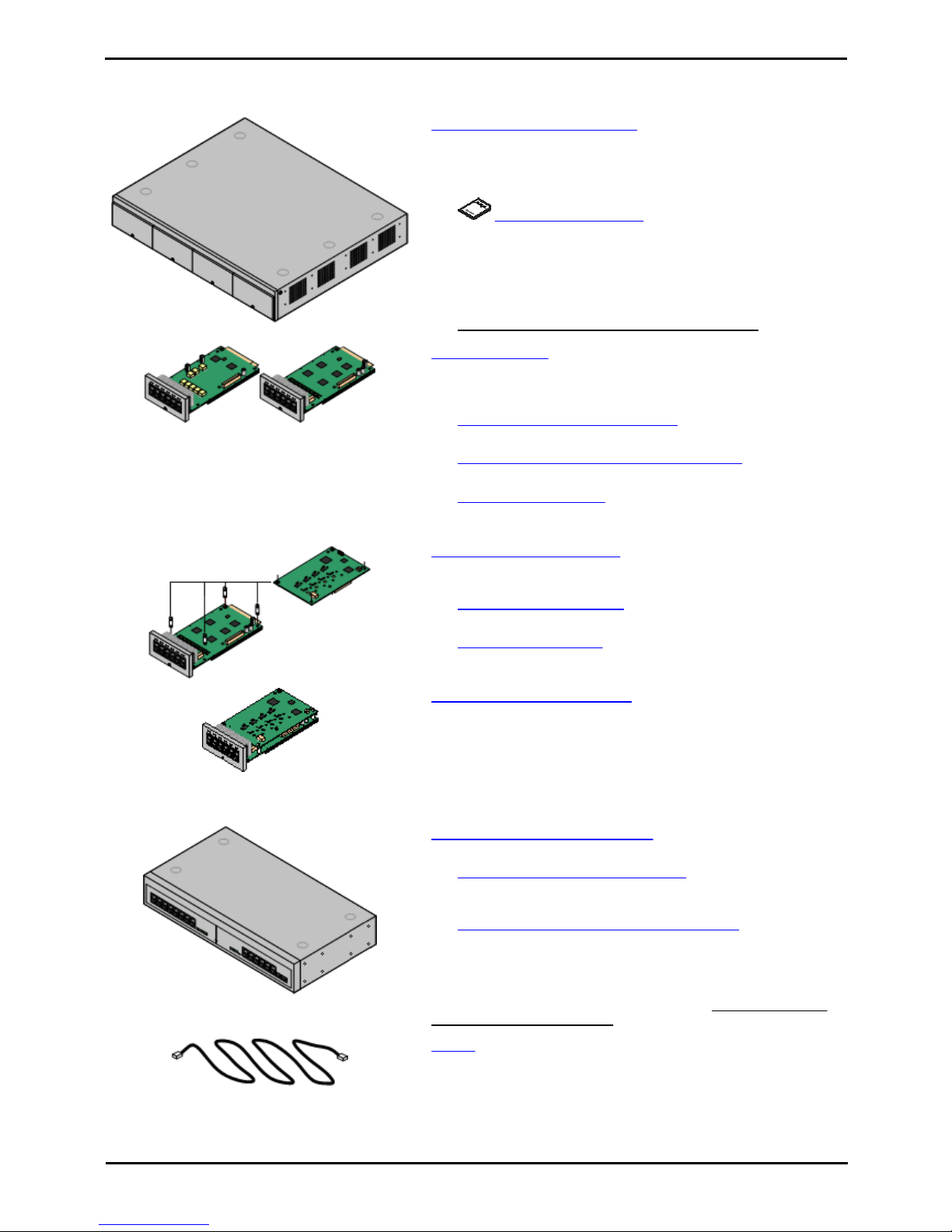
· IP Office IP500 V2 Control Unit
The control unit holds the main configuration and performs the
routing and switching for telephone calls and data traffic. The
control unit includes 4 slots for optional base cards to support
trunk and phone extension ports.
·
Avaya System SD Card
This card is used to hold system files and provide voicemail.
The card has a unique serial number which is is used to
validate license keys entered into the system's configuration.
The card is mandatory for correct system operation.
· Power Cord
The control unit is not supplied with a power cord. An
IEC60320 C13 type earthed power cord is required.
· IP500 Base Cards
The IP500 control unit has slots for up to 4 IP500 base cards.
These can be used to add analog, ETR and digital phone extension
ports.
· IP500 Digital Station 8 Base Card
(Maximum 3)
Each card supports up to 8 1400 series phones.
· IP500 Analog Phone 2/Phone 8 Base Cards (Maximum 4)
Each card supports 2 or 8 analog phones.
· IP500 ETR6 Base Card (Maximum 3)
Each card supports up to 6 ETR phones (only 2 ETR34 or
ETR34D phones).
· IP500 Trunk Daughter Cards
The IP500 base cards can be fitted with an IP500 trunk daughter
card in order to support trunk connections.
· IP500 Analog Trunk Card (Maximum 4)
This card provides 4 analog trunk connections.
· IP500 PRI Trunk Card
(Maximum 1)
This card provides a single PRI/T1 trunk connection.
· IP500 ATM Combination Cards (Maximum 2)
This card is a pre-paired base and daughter card. It provides 6
digital station ports, 2 analog phone ports, 10 VCM channels and 4
analog trunk ports. The trunk daughter card cannot be removed or
replaced with another type.
· VCM channels are required for support of SIP trunks. This is
the only type of card that provides VCM channels for IP Office
Essential Edition - PARTNER® Version.
· IP500 External Expansion Module
One external expansion module can be added.
· IP500 Phone 16 Expansion Module
This type of external module adds support for 16 additional
analog phone extensions.
· IP500 Digital Station 16 Expansion Module
This type of external module adds support for 16 additional
ports for 1400 Series phones.
· Power Cord
The external expansion modules include an external power supply
unit but do not include a mains power cord. An IEC60320 C13 type
earthed power cord is required.
· Cables
The IP Office is designed primarily for connection to a structured
cabling system using CAT3 UTP cabling. This approach allows
telephone and data traffic to share the same wiring infrastructure
and simplifies equipment moves.

PARTNER Version Installation Manual Page 9
- Issue 1c (09 April 2010)IP Office Essential Edition
System Overview: System Components
· Mounting Kits
The control unit can be used free-standing, with external
expansion modules stacked above it. However mounting kits exist
to allow alternate installation methods.
· Wall Mounting Kit
With an optional wall mounting kit the control unit can be wall
mounted. However it cannot support any external expansion
modules when wall mounted.
· Rack Mounting Kit
With optional rack mounting kits, the control unit and external
expansion modules can also be rack mounted.
· Surge Protectors and Barrier Boxes
Where the installation includes extensions in other buildings
additional protective equipment is required. This equipment may
also be required in areas where the lightning risk is high.
· Phones
The following phones are supported on IP Office Essential Edition PARTNER® Version systems:
· ACS "Refreshed" Series
ETR6D, ETR18D, ETR34D, 3910 and 3920.
· ACS "Euro" Series
ETR6, ETR18, ETR18D, ETR34D.
· 1400 Series
1403, 1403SW, 1408, 1416.
· Analog Phones
· Application DVDs
The IP Office applications can be ordered on a number of DVDs. In
addition they can be downloaded from the IP Office section of the
Avaya support web site (http://support.avaya.com).

PARTNER Version Installation Manual Page 10
- Issue 1c (09 April 2010)IP Office Essential Edition
1.2 Features Summary
The following features are supported:
· Up to 48 extensions port. Extension types can be a mix of analog, digital and ETR.
· Analog DTMF phones are supported. Due to the wide range of such phones, it is the installers responsibility to
validate the operation of any specific analog phone with the IP Office system before installing them on a
customer system.
· IP Office digital station (DS) extension ports support Avaya 1400 Series phones.
· IP Office ETR extension ports support Avaya PARTNER ETR phones.
· Up to 56 lines using a combination of analog, T1/PRI and SIP trunks.
· Up to 12 analog trunks.
· Up to 24 channels using a single PRI trunk connection.
· Up to 20 SIP channels using SIP trunks. 3 channels are supported without licenses, additional channels require
the addition of licenses.
· Key System Functionality
· The first two buttons on phones are fixed as intercom buttons for internal call functions.
· For systems with analog trunks, by default the first 5 analog trunks are assigned to line buttons. Additional
lines including non-analog can be assigned by the system maintainer.
· Buttons not assigned as intercom or line buttons can be set to other functions by the system maintainer or by
system users.
· System maintenance
· Users with a suitable phone (1408, 1416, ETR18D or ETR34D) can performs a range of personal programming
tasks.
· The users on extensions 10 and 11 can perform system programming tasks in addition to personal
programming.
· IP Office Manager supports a dedicated IP Office Essential Edition - PARTNER® Version system programming
mode to allow programming from a PC.
· Embedded voicemail
· Mailboxes enabled by default for all users.
· Up to 15 hours message storage in total. Maximum message length 3 minutes.
· Single auto attendant support for incoming calls.
· Station Metering Detail Reporting (SMDR) output from the IP Office to an IP enabled call logger.
· 64-Party conferencing supports for multiple conferences totalling up to 64 conference parties.
· Loudspeaker connection via an analog extension port connection. This port can then be paged directly or in
conjunction with paging to a hunt group.
· Port for external music on hold source connection.
· External switch control port for connection of up to 2 door relay controls or similar.

PARTNER Version Installation Manual Page 11
- Issue 1c (09 April 2010)IP Office Essential Edition
System Overview: Features Summary
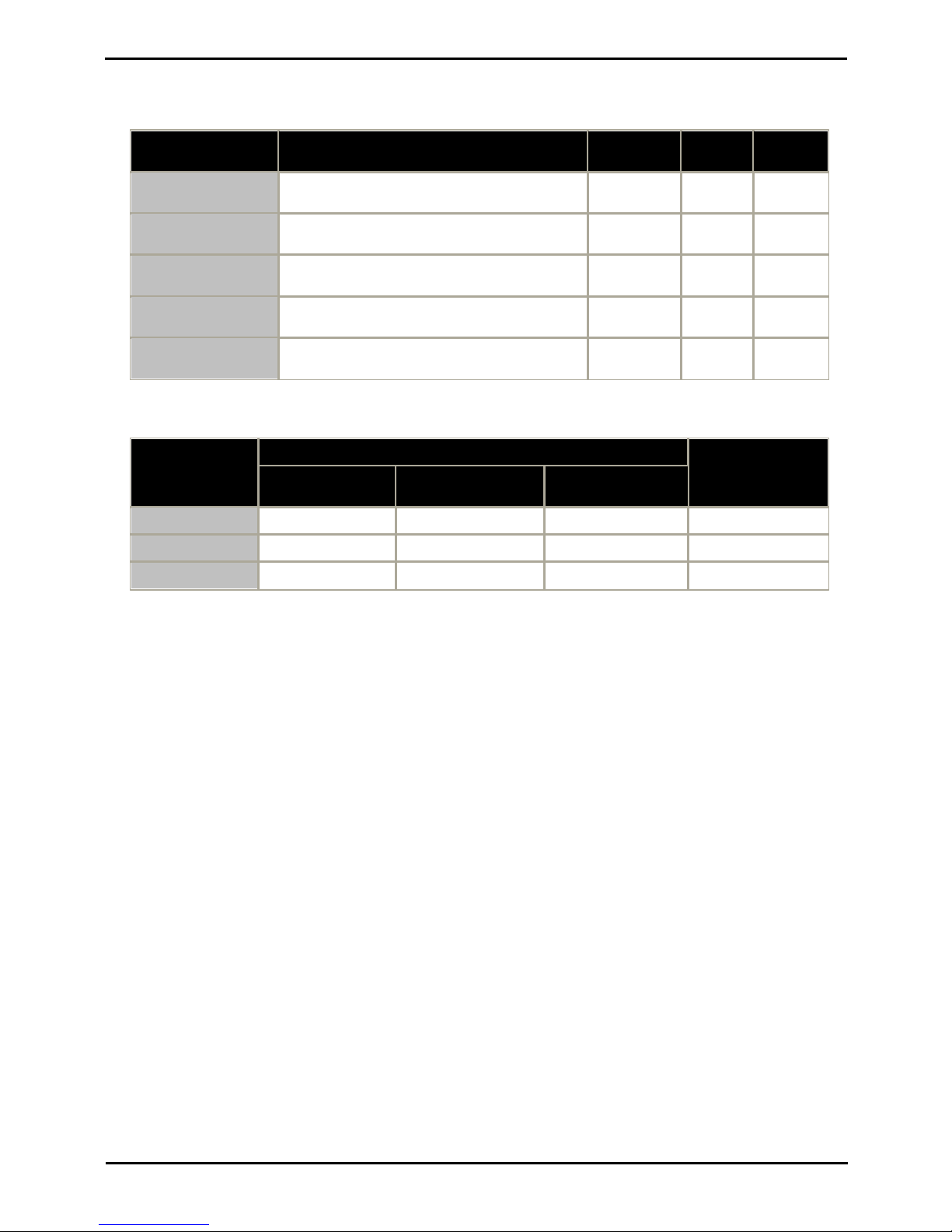
1.3 System Capacity/Planning Rules
Maximum Component Capacities
Component
Maximum
IP500 Base Cards
4
Description
IP500 Phone 8 Base Card
4
Provides ports for 8 analog phone extension.
IP500 Phone 2 Base Card
4
Provides ports for 2 analog phone extensions.
IP500 Digital Station 8 Base Card
3
Provides ports for 8 1400 Series phone extensions.
IP500 ETR6 Base Card
3
Provides ports for 6 ETR phone extensions.
IP500 ATM Combination Card
2
Provides ports for 6 1400 Series phone extensions and 4
analog trunks.
IP Office 500 Daughter Cards
4
IP500 Analog Trunk Daughter Card
3
Supports 4 analog trunks.
IP500 PRI 1 Trunk Daughter Card
1
Supports a single PRI/T1 trunk connection.
IP Office 500 External Expansion
Modules
1
IP500 Phone 16
1
Provides ports for 16 analog phone extensions.
IP500 Digital Station 16
1
Provides ports for 16 1400 Series phone extensions.
Maximum System Capacity
Extensions
Maximum
48
1400 Series Phones
46
3 x DS8 Base Cards, 1 x ATM Combination Card and 1 x
Digital Station 16 External Expansion Module.
ETR Phones
18
3 x ETR6 Base Cards.
Analog Phones
48
4 x Phone 8 Base Cards.
Trunks
56
Analog Trunks
12
Using any combination of IP500 ATM4 Trunk Daughter cards
mounted on the IP500 base cards or up to 2 IP500 ATM
Combination Cards.
T1 Channels
24
1 x IP500 PRI Trunk Daughter Card mounted on one of the
IP500 base cards.
PRI Channels
23
SIP Trunk Channels
20
3 Channels are supported without licenses. Additional
channels must be licensed.
Notes
While base cards can be installed in any slot and daughter cards added to any base card, the following should be
considered when planning the installation.
· The first two extensions (extensions 10 and 11) provided by slot 1 of the control unit are used as system
administrator extensions if a card providing digital station or ETR ports is fitted. If a card supporting only analog
extension ports is fitted in the first slot, system administration can only be done using the IP Office Manager
application.
· While the IP500 Analog Trunk Daughter card can be fitted to any IP500 base card, when fitted to an IP500 Phone 8
Base Card the combination provides additional power fail ports.

PARTNER Version Installation Manual Page 12
- Issue 1c (09 April 2010)IP Office Essential Edition
1.4 SD Cards
The system control unit has two SD card slots; labeled System SD and Optional SD.
An Avaya IP Office PARTNER SD card is required in the System slot at all times. This card is used for critical system file
storage. It is also has a unique serial number which for the generation and validation of feature licenses used by the
system. This card is also used for the storage of prompts, greetings and messages by the voicemail system.
The Optional SD card slot can be used with any SD card meeting the specification below. The card in this slot can be used
for a number of maintenance processes.
· SDHC minimum 4GB FAT32 format (Single partition, SDHC, class2+, FAT32, SPI & SD bus).
SD Card Removal
SD cards should never be removed while being used. Though the SD card slot LEDs indicate when data is being
written to an SD card, lack of flashing LED is not a sufficient safeguard. The IP Office Manager provides methods to
shutdown and restart an individual card or to shutdown the system in order to allow removal of an SD card. If the
System SD card is removed, licensed features will continue operating for up to 2 hours.
PARTNER Version Installation Manual Page 13
- Issue 1c (09 April 2010)IP Office Essential Edition
System Overview: SD Cards
1.5 Base Cards
The control unit has 4 slots for the insertion of base cards. The slots are
numbered 1 to 4 from left to right. Normally they can be used in any order,
however if the capacity for a particular type of card is exceeded, the card in
the rightmost slot will be disabled.
Each base card includes an integral front panel with ports for cable
connections. Typically the first 8 ports on the left are for connection of
extension devices. The 4 ports on the left are used for connection of trunks
if a trunk daughter card
is added to the base card.
IP500 Digital Station Base Card
This card provides 8 DS (digital station) ports for the connection of
Avaya digital phones other than IP phones.
· The card can be fitted with an IP500 trunk daughter card which uses
the base card ports for trunk connection.
· Maximum: 3 per control unit.
· 4400 Series phones (4406D, 4412D and 4424D) are not supported
on this card. They are supported on an external expansion module.
IP500 Analog Phone Base Card
The card is available in two variants, supporting either 2 or 8 analog
phone ports.
· The card can be fitted with an IP500 trunk daughter card which uses
the base card ports for trunk connection.
· Maximum: 4 per control unit.
· The analog phone ports do not include a ringing capacitor. Where this
is a requirement, connection should be via a Master socket containing
ringing capacitors.
· If fitted with an IP500 Analog Trunk daughter card, during power
failure phone port 8 is connected to analog trunk port 12.
IP500 ATM Combination Card
This card provides 6 digital station ports (1-6), 2 analog extension ports
(7-8) and 4 analog trunk ports (9-12). The card also includes 10 VCM
channels.
· This card has a pre-installed IP500 analog trunk daughter card.
· Maximum: 2 combination cards per IP500 V2 control unit. Not
supported by IP500 control units.
· The analog phone ports do not include a ringing capacitor. Where this
is a requirement, connection should be via a Master socket containing
ringing capacitors.
· If fitted with an IP500 Analog Trunk daughter card, during power
failure phone port 8 is connected to analog trunk port 12.

PARTNER Version Installation Manual Page 14
- Issue 1c (09 April 2010)IP Office Essential Edition
IP500 ETR6 Base Card
This card provides 6 ETR ports for connection of ETR phones. 2 Analog
extension ports are also provided for emergency use only with an
analog trunk card.
· The card can be fitted with an IP500 trunk daughter card which uses
the base card ports for trunk connection.
· Maximum: 3 per IP500 V2 control unit. Not supported by IP500
control units.
· The analog phone ports do not include a ringing capacitor. Where this
is a requirement, connection should be via a Master socket containing
ringing capacitors.
· If fitted with an IP500 Analog Trunk daughter card, during power
failure phone ports 7 and 8 are connected to analog trunk port 12.
However during normal operation analog phone ports 7 and 8 are not
useable.

PARTNER Version Installation Manual Page 15
- Issue 1c (09 April 2010)IP Office Essential Edition
System Overview: Base Cards
1.6 Trunk Cards
The IP500 base cards can be fitted with an IP500 daughter cards to
support the connection of trunks to the base card.
Each daughter card is supplied with the stand off pillars required for
installation and a label to identify the daughter cards presence on the
front of the base card after installation.
· IP500 Combination cards are pre-fitted with a trunk daughter card
which cannot be removed or changed for another type of trunk
daughter card.
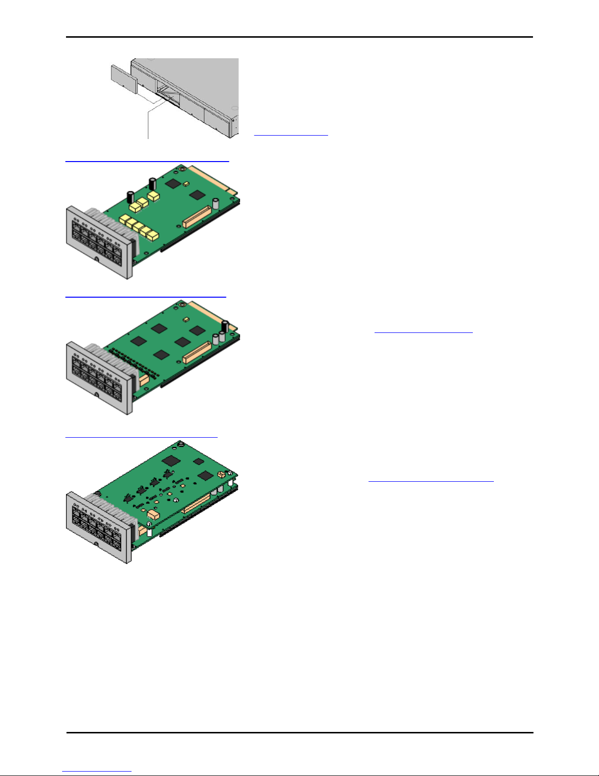
IP500 Analog Trunk Daughter Card
This card allows the base card to support 4 analog loop-start trunks.
· The analog phone ports do not include a ringing capacitor. Where
this is a requirement, connection should be via a Master socket
containing ringing capacitors.
· If fitted with an IP500 Analog Trunk daughter card, during power
failure phone port 8 is connected to analog trunk port 12.
· Maximum: 3 per IP500 control unit.
IP500 PRI-U Trunk Daughter Card
This card allows the base card to support 1 PRI trunk connections.
The card is available in single and dual port variants. The card can be
configured for T1 robbed bit or T1 PRI.
· Maximum: 1 per IP500 control unit.
PARTNER Version Installation Manual Page 16
- Issue 1c (09 April 2010)IP Office Essential Edition
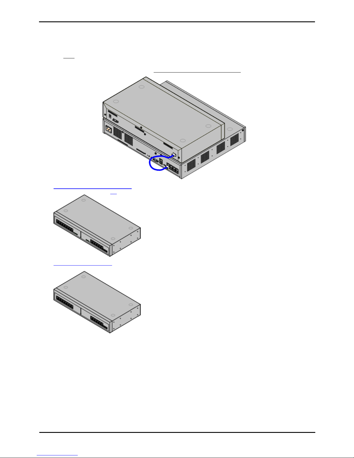
1.7 External Expansion Module
An external expansion module can be used to add extra ports to the system. Only one external expansion unit is
supported.
· The external expansion module is supplied with a blue 1 meter (3'3'') expansion interconnect cable. This cable
must be used when connecting to expansion ports on the rear of a control unit.
Each module uses an external power supply unit supplied with the module. A locale specific power cord for the PSU must
be ordered separately. Both types of module use an IEC60320 C13 type earthed power cord.
· IP500 Digital Station 16 Module
Provides an additional 16 DS ports for 1400 Series phones.
· IP500 Phone 16 Module
Provides an additional 16 PHONE ports for analog phones.

PARTNER Version Installation Manual Page 17
- Issue 1c (09 April 2010)IP Office Essential Edition
System Overview: External Expansion Module
1.8 Supported Phones
The following phones are supported on IP Office Essential Edition - PARTNER® Version systems:
Telephones
Port
Type
Intercom
Button
Programmable
Buttons
Total
Buttons
Display
Handsfre
e
Aux Port
User/
System
Prog
...with
lights
...
without
lights
ACS "Refreshed" Series
ETR6D
ETR24–6
Yes
Yes––
ETR18D
ETR216422
Yes
Yes
Yes
Yes
ETR34D
ETR232438
Yes
Yes
Yes
Yes
3910
ETR2–6Yes
Yes––
3920
ETR2–6Yes
Yes––
ACS "Euro" Series Phones
ETR6
ETR24-6NoYes––
ETR18
ETR216422NoYes
Yes
–
ETR18D
ETR216422
Yes
Yes
Yes
Yes
ETR34D
ETR232438
Yes
Yes–Yes
1400 Series Phones
1403/1403S
W
DS21–3
Yes
Yes––
1408DS26–8Yes
Yes–Yes
1416DS214–16Yes
Yes–Yes
· Analog Phones: Any analog phones to be used with the system should be tested and validated by the installer before
use.
Notes
1.
ETR34 phones are limited to 2 per IP500 ETR6 base card and a maximum of 4 per system.
2.
The ETR phones support attachment of an additional analog phone via the ETR phones Aux socket. Such analog
phones operate with the same extension number as the ETR extension to which they are attached.
3.
The 1416 can be used with DBM32 button modules to provide additional programmable buttons. Up to 3 DBM32
button modules can attached to a 1416.
4.
The 3910 and 3920 are single handset DECT systems. The handset base station attaches to an analog port.
PARTNER Version Installation Manual Page 18
- Issue 1c (09 April 2010)IP Office Essential Edition
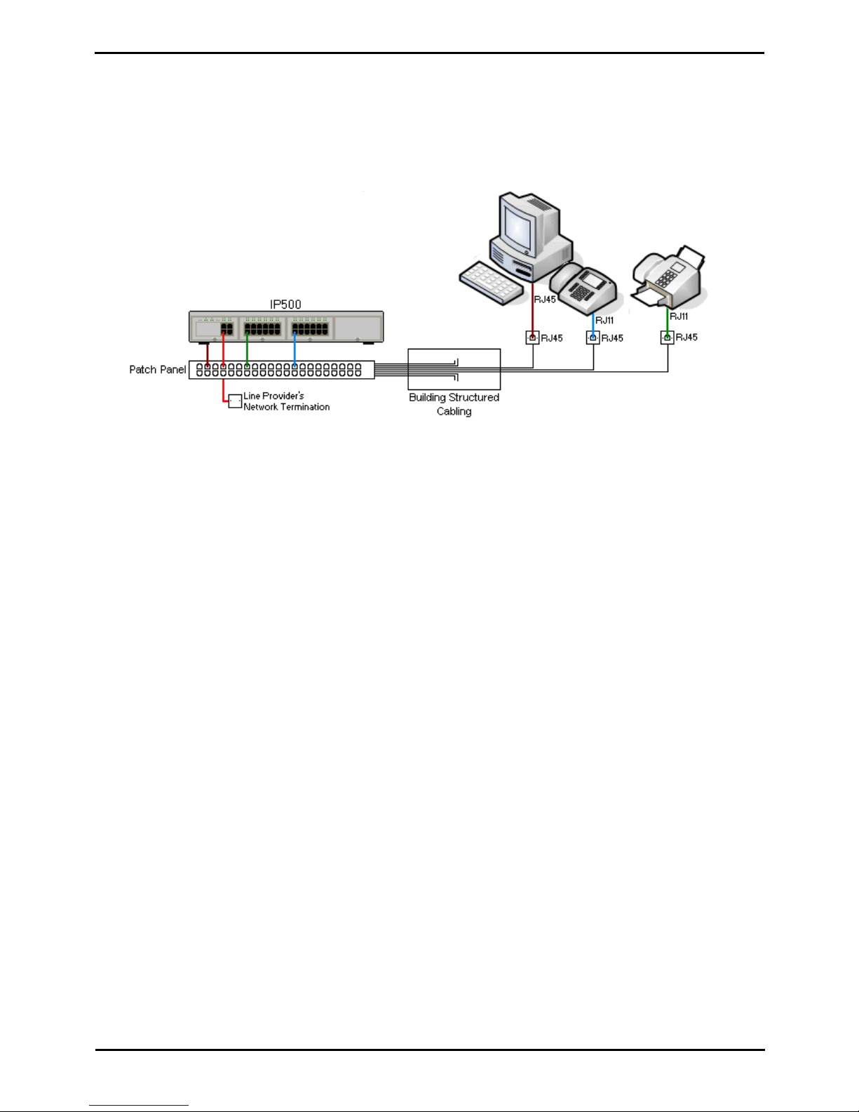
1.9 Cabling and Cables
The system is designed primarily for use within an RJ45 structured cabling system using CAT3 unshielded twisted-pair
(UTP) cabling and RJ45 sockets.
A structured cabling system is one where cables are run from a central RJ45 patch panel in the communications/data room
to individual RJ45 sockets at user's desk. All wires in each cable between the patch panel and the desk socket are
connected straight through. This arrangement allows devices connected at the patch panel to be swapped to match the
type of device that needs to be connected at the user socket. For example, making one user socket a phone port and
another user socket a computer LAN port, without requiring any rewiring of the cables in between.
· Traditional IDC Punchdown Wiring Installations
Where necessary, the far end RJ45 plug can be stripped from IP Office cables and wired into traditional wiring
systems using punch-block connectors. This type of installation should be performed by an experienced wiring
technician.
· Trunk Connections
The majority of IP Office trunk ports use RJ45 connectors for acceptance of an RJ45-to-RJ45 cable. However,
connection at the line providers end may require use of a different plug type in order to match the line providers
equipment.
· RJ11 Phone Connectors
Many phones use RJ11 sockets and are supplied with RJ11-to-RJ11 cables. RJ11 plugs can be inserted into RJ45
sockets and in many case the connection will work. However this is not recommended or supported as the
connection lock is not truly positive and may become disconnected. An RJ45-to-RJ11 cable should be used for
these connections.
PARTNER Version Installation Manual Page 19
- Issue 1c (09 April 2010)IP Office Essential Edition
System Overview: Cabling and Cables
Standard IP Office Cables
The following are Avaya standard cables available for use with IP Office systems. The maximum length is applicable if the
standard Avaya cable is replaced with an alternative cable.
Cable
Description
Part number
Standard
Length
Maximum
Length
9-Way DTE Cable
Connects to control unit RS232 DTE port. 9-Way Dtype plug to 9-way D-type socket.
–
2m/6'6''.
2m/6'6''.
Structured Cabling DS
Line Cable
Connects from RJ45 sockets to RJ11 socketed
digital station and analog phones.
700047871
4m/13'2''.
See table
below.
PRI Trunk Cable
Connects PRI trunk ports to the line providers
network termination point. RJ45 to RJ45. Red.
700213440
3m/9'10''.
–
Expansion
Interconnect Cable
Connects the control unit to expansion module.
RJ45 to RJ45. Blue.
700213457
1m/3'3''.
1m/3'3''.
LAN Cable
Connects from IP Office LAN ports to IP devices.
RJ45 to RJ45. Grey.
700213481
3m/9'10''.
100m/328'.
The table below details the maximum total cable distances for DS and analog extensions using different cable types.
Telephone
Unshielded Twisted-Pair (UTP) - 50nf/Km
CW1308
AWG22
(0.65mm)
AWG24
(0.5mm)
AWG26
(0.4mm)
1400 Series
1000m/3280'.
1000m/3280'.
400m/1310'.
400m/1310'.
ETR
1000m/3280'.
1000m/3280'.
400m/1310'.
–
Analog Phones
1000m/3280'.
1000m/ 3280'.
400m/1640'.
800m/2620'.

PARTNER Version Installation Manual Page 20
- Issue 1c (09 April 2010)IP Office Essential Edition
1.10 Emergency and Power Failure Ports
IP Office systems can provide 2 types of analog extension power failure ports. These are:
Type
Description
Provided By:
Switching Power
Failure Ports
During normal IP Office operation these ports
can be used for normal analog phone
connection.
During power failure the port is directly
connected to an analog trunk port.
· IP500 Analog Phone 8 Card
When an IP500 Analog Phone 8 base card is
fitted with an IP500 Analog Trunk daughter
card, during power failure extension port 8 is
connected to analog trunk port 12.
· IP500 ATM Combination Card
On this card, during power failure, extension
port 8 is connected to analog trunk port 12.
Emergency Only Power
Failure Ports
During normal IP Office operation these ports
cannot be used.
During power failure the port is directly
connected to an analog trunk port.
· IP500 Analog Trunk Daughter Card
Regardless of the IP500 card hosting it,
during power failure pins 4 and 5 of port 12
are connected to pins 7 and 8.
· IP500 ETR6 Card
On this card, during normal operation
extension ports 7 and 8 are not useable.
However, if the card is fitted with an IP500
Analog Trunk daughter card, during power
failure extension ports 7 and 8 are
connected to analog trunk port 12.
In all cases these only work with loop-start analog trunks. Any phones connected to these ports should be clearly labeled
as power fail extensions in accordance with the appropriate national and local regulatory requirements.
PARTNER Version Installation Manual Page 21
- Issue 1c (09 April 2010)IP Office Essential Edition
System Overview: Emergency and Power Failure Ports
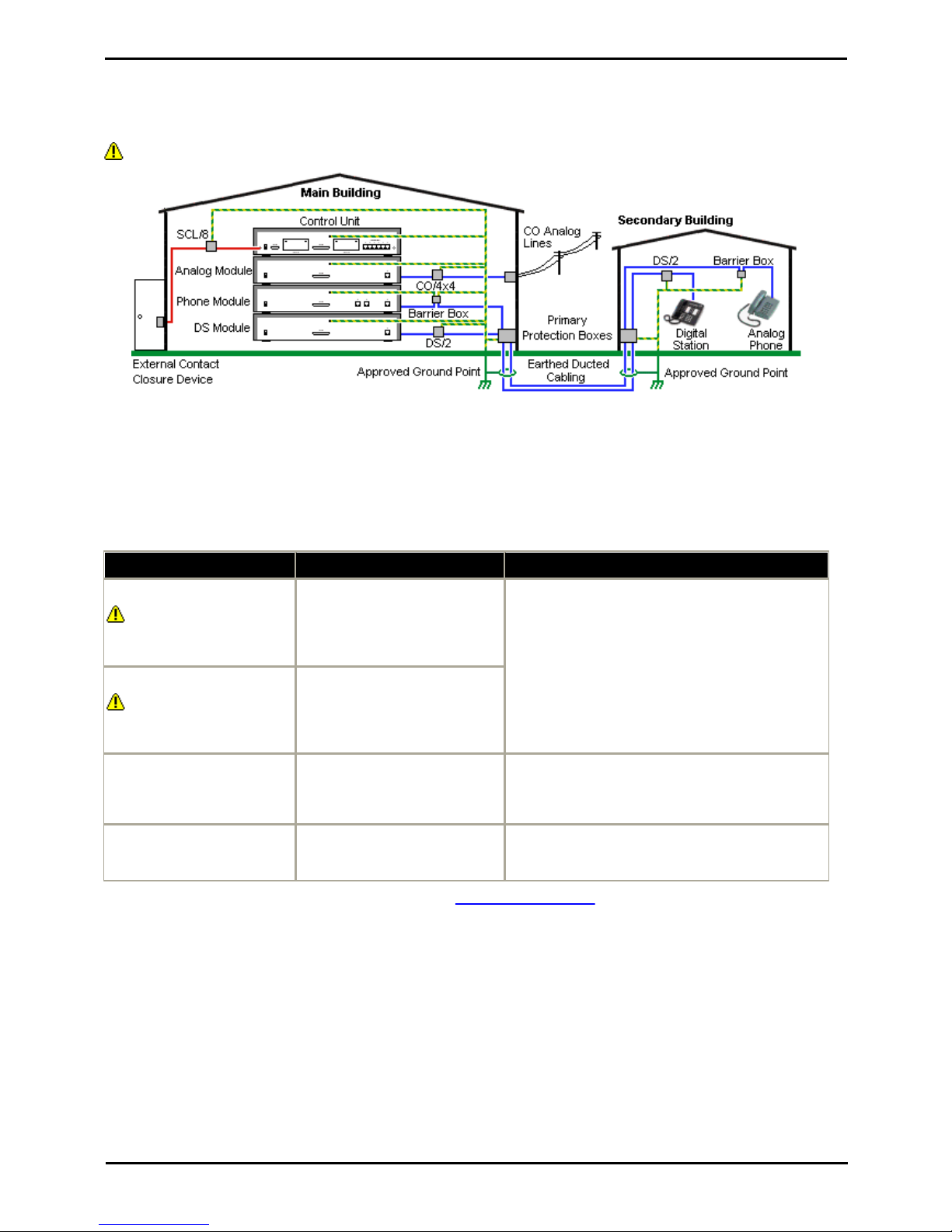
1.11 Out of Building Connections
The following are the only supported scenarios in which wired extensions and devices outside the main building can be
connected to the IP Office Essential Edition - PARTNER® Version system. In these scenarios, additional protection, in the
form of protective grounding and surge protectors, must be fitted.
The fitting of additional protection does not remove the risk of damage. It merely reduces the chances of damage.
Cabling Requirements
· Cables of different types, for example trunk lines, extensions, ground and power connections, should be kept separate.
· All cabling between building should be enclosed in grounded ducting. Ideally this ducting should be buried.
· A Primary Protection Box must be provided at the point where the cables enter the building. This should be three point
protection (tip, ring and ground). Typically this would be gas tube protection provided by the local telephone company.
The ground wire must be thick enough to handle all the lines being affected by indirect strike at the same time.
Connection Type
Protection Device Type
Requirement
DS Phone Extensions
Digital Station Expansion
module DS ports only.
ITWLinx towerMAX DS/2
Supports up to 4 connections.
(This device was previously
referred to as the Avaya 146E).
· Connection from the expansion module to the
phone must be via a surge protector at each end
and via the primary protection point in each
building.
· The IP Office expansion module and control unit
and IROB devices must be connected to the
protective ground point in their building.
· The between building connection must be via
earthed ducting, preferable underground. The cable
must not be exposed externally at any point.
Analog Phone Extensions
Phones Expansion module (
POT or PHONE) ports only.
IP Office Barrier Box
Supports a single connection.
Maximum of 16 on any expansion
module.
Analog Trunks
ITWLinx towerMAX CO/4x4
Supports up to 4 two-wire lines.
(This device was previously
referred to as the Avaya 146C).
For locations where the risk of lightning strikes is felt
to be high, additional protection of incoming analog
trunks is recommended.
External Output Switch
ITWLinx towerMAX SCL/8
(This device was previously
referred to as the Avaya 146G)
Connections from an IP Office Ext O/P port to an
external relay device must be via a surge protector.
* The towerMAX range of devices are supplied by ITWLinx (http://www.itwlinx.com).

PARTNER Version Installation Manual Page 22
- Issue 1c (09 April 2010)IP Office Essential Edition
1.11.1 DS Phones
When digital phone extensions are required in another building, additional In-Range Out-Of-Building (IROB) protective
equipment must be used. For phones connected to IP Office DS ports, the supported device supplied by ITWLinx is a
towerMAX DS/2* module. This IROB device was previous badged by Avaya as the 146E IROB.
The protection device should be installed as per the instructions supplied with the device. The ground points on the IP
Office control unit and the DS modules must be connected to a protective ground using 18AWG wire with a green and
yellow sleeve.
Typically the IROB
2 RJ45 EQUIPMENT ports are straight through connected to the 2 RJ45 LINE ports. This allows existing RJ45 structured
cabling, using pins 4 and 5, to be used without rewiring for up to two DS connection. However each of these ports can be
used to connect a second extension using pins 3 and 6.
LINE
Signal
EQUIPMENT
1
Not used.
1
2
Not used.
2
3
Ring II (Optional)
3
4
Ring I
4
5
Tip I
5
6
Tip II (Optional)
6
7
Not used.
7
8
Not used.
8
* The towerMAX range of devices are supplied by ITWLinx (http://www.itwlinx.com).
PARTNER Version Installation Manual Page 23
- Issue 1c (09 April 2010)IP Office Essential Edition
System Overview: Out of Building Connections
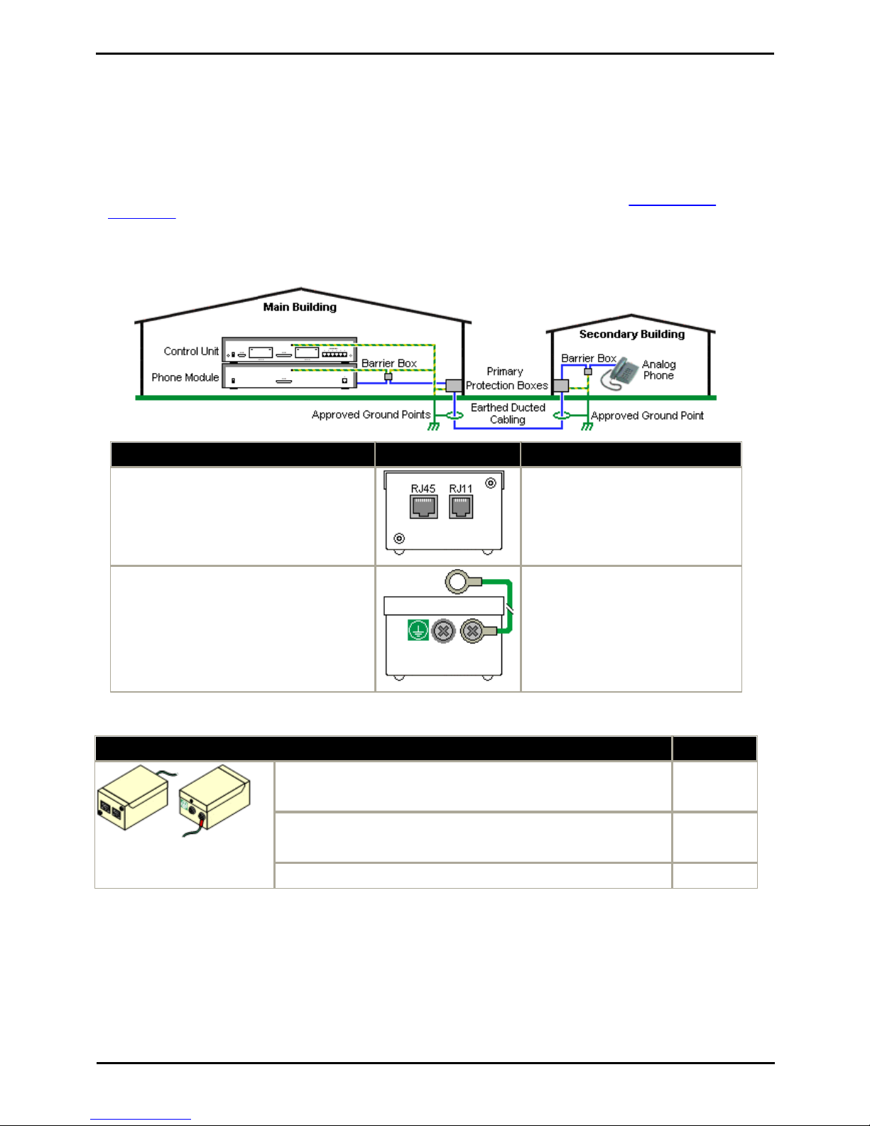
1.11.2 Analog Phone Barrier Box
Where analog phone extensions are required in another building, additional protective equipment must be used, in the
form of IP Office Phone Barrier Boxes and protective earth connections.
· The correct IP Office specific barrier boxes must be used. These modules have been designed specifically for the
signalling voltages used by the IP Office Essential Edition - PARTNER® Version system:
· Only the IP Office Phone Barrier Box V2 should be used.
· No other type of analog phone barrier box should be used.
· Where more than 3 barrier boxes are required in a building, they must be rack mounted using a Barrier Box rack
mounting kit.
· A maximum of 16 barrier boxes can be used with any Phone module.
· CAUTION: PHONE (POT) ports on the front of control units must not be used for extensions that are external to the
main building.
Main Building
Barrier Box
Secondary Building
· RJ11: Connect to PHONE (POT) port on the
Phone module using cable supplied with the
barrier box.
· RJ45: Connect to the secondary building
barrier box via primary protection in both
buildings.
· RJ11: Connect to analog phone.
Cable not supplied.
· RJ45: From main building via primary
protection in both buildings.
· Center Screw: Connect to main building
protective ground (or ground terminal of
Barrier Box Rack Mounting Kit). Use 18AWG
(minimum) wire with a green and yellow
sleeve.
· Right-Hand Screw: Connect to ground point
on Phone module using ground cable supplied
with barrier box.
· Center Screw: Connect to main
building protective ground. Use
18AWG (minimum) wire with a green
and yellow sleeve.
· Right-Hand Screw: Not used.
Wires from external telephone going directly to the barrier boxes must be kept apart, that is not routed in the same
bundle:
IP Office Barrier Boxes
Part number
IP Office 500 Phone Barrier Box (81V)
Use with Phone V1 module. Includes an RJ45 to RJ11 cable and a
functional earth lead.
700293897
IP Office 500 Phone Barrier Box V2 (101V)
Use with Phone V2 module. Includes an RJ45 to RJ11 cable and a
functional earth lead.
700385495
Barrier Box Rack Mounting Kit
700293905
PARTNER Version Installation Manual Page 24
- Issue 1c (09 April 2010)IP Office Essential Edition
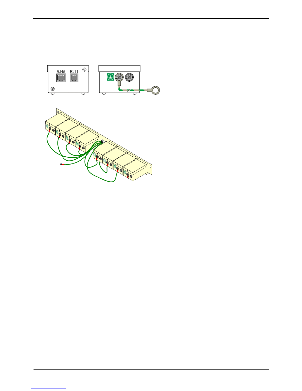
1.11.3 Rack Mounting Barrier Boxes
Where more than 3 Phone Barrier Boxes are used they must be rack mounted. The Barrier Box Rack Mounting Kit (Part
number 700293905) supports up to 8 Phone Barrier Boxes.
1.
Unscrew the two screws arranged diagonally at the front of each barrier box and use these same screws to reattach
the barrier box to the rack mounting strip.
2.
Each barrier box is supplied with a solid green ground wire connected to its functional ground screw. Remove and
discard this wire. Connect a green/yellow ground wire to the protective earth screw in the center of the Point on the
back of the Barrier Box.
3.
The rack mounting strip has threaded M4 earthing pillars. Connect the free end of the barrier box ground wire,
using M4 washers and nuts, to the earthing pillar on that side of the rack mounting strip.
4.
Using 14AWG wire with green and yellow sleeve, connect one of the earthing pillars to the buildings protective
earth.
5.
Using 14AWG wire with green and yellow sleeve, connect the other earthing pillar to the Phone module.
6.
Ensure that the following wires are not routed together in the same bundle:
· Earth lead from the barrier box to the Phone 8/16/32.
· Internal wires, e.g. wires going directly to the Phone 8/16/32.
· Wires from external telephone going directly to the barrier boxes.

PARTNER Version Installation Manual Page 25
- Issue 1c (09 April 2010)IP Office Essential Edition
Installation Requirements
Chapter 2.

PARTNER Version Installation Manual Page 26
- Issue 1c (09 April 2010)IP Office Essential Edition
2. Installation Requirements
2.1 Environmental Requirements
The planned location must meet the following requirements. If being installed into a rack system, these are requirements
for within the rack:
1.
o Temperature: 0°C to 40°C / 32°F to 104°F.
2.
o Humidity: 10% to 95% non-condensing.
3.
o Check there are no flammable materials in the area.
4.
o Check there is no possibility of flooding.
5.
o Check that no other machinery or equipment needs to be moved first.
6.
o Check that it is not an excessively dusty atmosphere.
7.
o Check that the area is unlikely to suffer rapid changes in temperature and humidity.
8.
o Check for the proximity of strong magnetic fields, sources of radio frequency and other electrical interference.
9.
o Check there are no corrosive chemicals or gasses.
10.
o Check there is no excessive vibration or potential of excessive vibration, especially of any mounting surface.
11.
o Check that where telephones are installed in another building, that the appropriate protectors and protective
grounds are fitted (see Out of Building Telephone Installation).
12.
o Check there is suitable lighting for installation, system programming and future maintenance.
13.
o Check that there is sufficient working space for installation and future maintenance.
14.
o Ensure that likely activities near the system will not cause any problems, e.g. access to and maintenance of any
other equipment in the area.
15.
o Where ventilation holes are present on any of the IP Office units, those holes should not be covered or blocked.
16.
o The surface must be flat horizontal for free-standing or rack mounted installations.
Wall Mounting
In additional to the requirements above, the following are applicable to IP Office units that support wall mounting.
1.
Units must only be mounted onto permanent wall surfaces.
2.
The surface must be vertical and flat.
3.
Orientation of the unit must be as shown in the section on IP500 Wall Mounting.
4.
The appropriate Avaya wall mounting kits must be used.
IMPORTANT SAFETY INSTRUCTIONS
When using your telephone equipment, basic safety precautions should always be followed to reduce the risk of fire,
electric shock and injury to persons, including the following:
1.
Do not use this product near water, for example, near a bath tub, wash bowl, kitchen sink or laundry tub, in a wet
basement or near a swimming pool.
2.
Avoid using a telephone (other than a cordless type) during an electrical storm. There may be a remote risk of
electric shock from lightning.
3.
Do not use the telephone to report a gas leak in the vicinity of the leak.
4.
Use only the power cord and batteries indicated in this manual.

PARTNER Version Installation Manual Page 27
- Issue 1c (09 April 2010)IP Office Essential Edition
Installation Requirements: Environmental Requirements
2.2 Space Requirements
IP Office control units and modules are designed to be installed either in a free-standing stack or into a 19" rack system.
Rack installation requires a rack mounting kit for each control unit and expansion module.
If being used without any external expansion modules, the IP500 and IP500 V2 control units can be wall mounted using a
wall mounting kit.
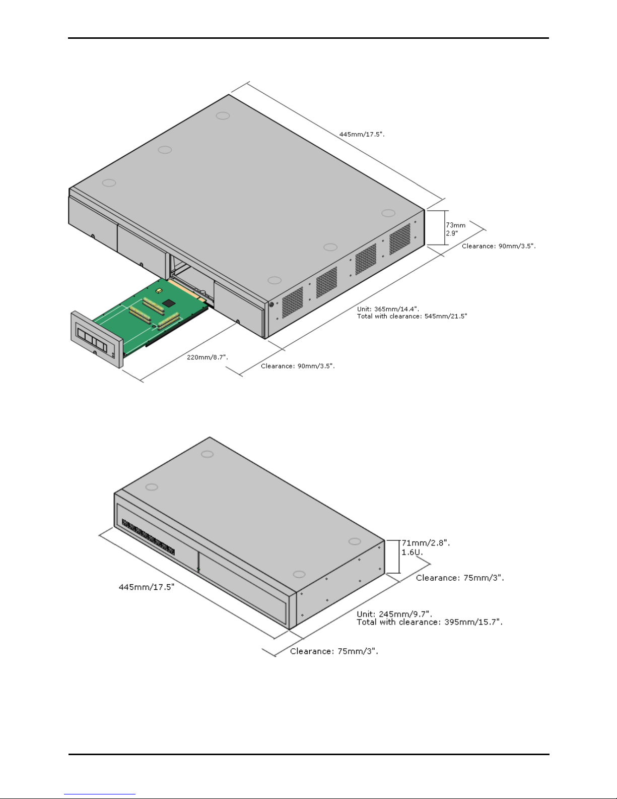
· Cable Clearance
Clearance must be provided at the front and rear of all modules for cable access and feature key dongle connection.
Allow a minimum clearance of 90mm (3.5 inches).
· Additional Clearance
Care should be taken to ensure that the positioning of the modules does not interrupt air flow and other factors that
may affect environmental requirements. This is especially important on IP500 and IP500 V2 control units which
have ventilation slots at the side.
· Cable Access
Power cords must not be attached to the building surface or run through walls, ceilings, floors and similar openings.
Installation measures must be taken to prevent physical damage to the power supply cord, including proper routing
of the power supply cord and provision of a socket outlet near the fixed equipment or positioning of the equipment
near a socket outlet.
PARTNER Version Installation Manual Page 28
- Issue 1c (09 April 2010)IP Office Essential Edition
2.2.1 IP500 and IP500 V2 Control Units
When wall mounted, a clearance of 500mm is required on all sides. The ventilation slots on the rear and sides should not
be covered or blocked.
2.2.2 IP500 Expansion Modules
The dimensions below are applicable to all IP500 external expansion modules.
PARTNER Version Installation Manual Page 29
- Issue 1c (09 April 2010)IP Office Essential Edition
Installation Requirements: Space Requirements
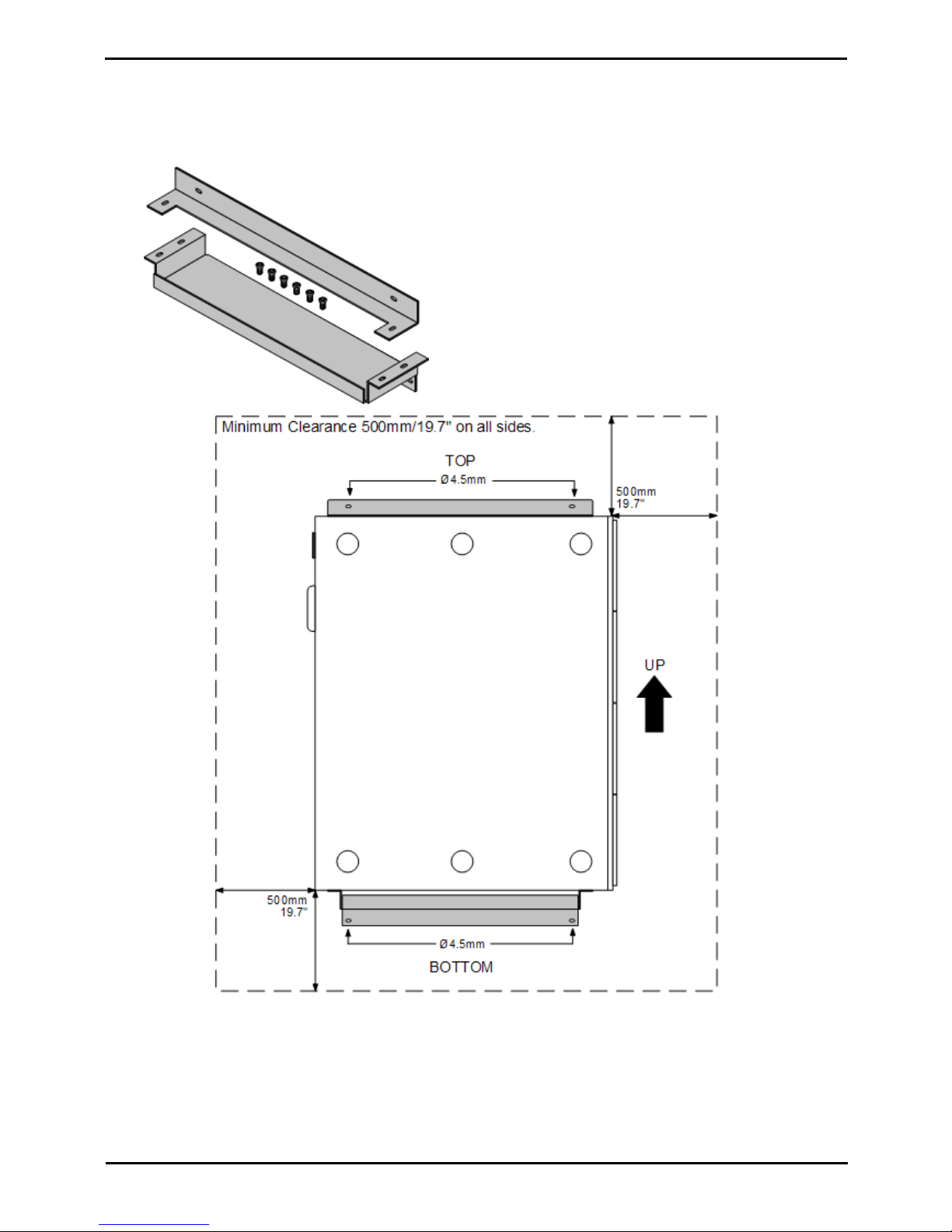
2.2.3 Wall Mounting
IP500 and IP500 V2 control units can be wall mounted if not using any external expansion modules. An IP500 wall
mounting kit is required in addition to suitable wall fixings.
· IP500 Wall Mounting Kit (SAP Code 700430150)
This kit must be used when wall mounting an IP500 or IP500 V2 control unit. Additional 4.5mm fixings suitable for
the wall type are required. A clearance of 500mm around the control unit is required.
PARTNER Version Installation Manual Page 30
- Issue 1c (09 April 2010)IP Office Essential Edition
2.2.4 Rack Space Requirements
All IP Office control units and external expansion modules can be rack mounted into standard 19" rack systems. Each unit
requires a 2U slot space within the rack. Rack mounting requires an IP500 rack mounting kit for each control unit and
external expansion module.
Where IP Office systems are being rack mounted, the effect of conditions within the rack cabinet must be considered. For
example the rack temperature may be above the room temperature and airflow within the rack will be restricted. The
environmental requirements for the individual IP Office units are still applicable inside the rack cabinet.
IP500 Rack Mounting Kit
· IP500 Rack Mounting Kit (SAP 700429202)
This kit contains all the components required for the rack mounting of
a single IP500 V2 control unit, IP500 control unit or IP500 external
expansion module. This includes screws for fixing of the brackets to
the module, bolts for securing the module in the rack and cable tidy
brackets.
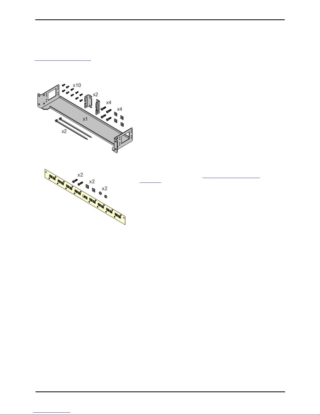
Barrier Box Rack Mounting Kit
· Barrier Box Rack Mounting Kit (SAP 700293905)
Barrier boxes must be used for out-of-building analog phone
extensions. This bracket allows up to 8 IP Office barrier boxes to be
rack mounted and simplifies the number of connections to the
protective ground point in the rack. This kit must be used when more
than 3 barrier boxes are in use and supports a maximum of 16
barrier boxes for a single external expansion module.
 Loading...