


Virtual Services Platform 7200
Table of contents
 Loading...
Installation Job Aid for Avaya Virtual
Services Platform 7200 Series
Release 4.2.1
NN47228-301
Issue 01.02
January 2015
Support
Go to the Avaya Support website at http://support.avaya.com for the most up-to-date
documentation, product notices, and knowledge articles. You can also search for release notes,
downloads, and resolutions to issues. Use the online service request system to create a service
request. Chat with live agents to get answers to questions, or request an agent to connect you to a
support team if an issue requires additional expertise.
Safety messages
Caution:
To protect the switch against ESD damage, take the following measures before you connect
data cables to the device:
• Always use antistatic wrist straps. Make sure you adjust the strap to provide good skin
contact.
• Ensure that you properly ground work surfaces and equipment racks for protection against
electrostatic discharge. You must connect the common point to the building ground wire. In
a properly wired building, the nearest reliable ground is typically at the electrical outlet.
• Avoid contact between equipment and clothing. The wrist or ankle strap protects only the
equipment from ESD voltages on the body; ESD voltages on clothing can still cause
damage.
• Avoid touching any connector pins.
• Do not remove the wrist or ankle strap until the installation is complete.
Caution:
When you mount this device in a rack, do not stack units directly on top of one another. You
must secure each unit to the rack with appropriate mounting brackets. Mounting brackets
cannot support multiple units.
©
2015 Avaya Inc. Installation Job Aid for Avaya Virtual Services Platform 7200 Series 1
Caution:
If you are not installing a redundant power supply in the slot, be sure to keep the metal cover
plate in place over the slot. Removing the cover plate impedes airflow and proper cooling of the
unit.
Warning:
Disconnecting the power cord is the only way to turn off power to this device. Allow at least 30
seconds for the this device to fully power down before restoring power. Otherwise, this device
might produce a core file during the reset leading to an extra delay during boot time.
Danger:
Use only power cords that have a grounding path. Without a proper ground, a person who
touches the switch is in danger of receiving an electrical shock. Lack of a grounding path to the
switch can result in excessive emissions.
Warning:
The lithium battery is not field replaceable. It should be removed and replaced by authorized
personnel only. Contact Avaya Technical Support for assistance if the battery requires
replacement.
Warning:
Fiber optic equipment can emit laser or infrared light that can injure your eyes. Never look into
an optical fiber or connector port. Always assume that fiber-optic cables are connected to a light
source.
Technical specifications
The following table provides the technical specifications for the individual switches in this series.
Ensure that the area where you install the switch and where it operates meets these requirements.
Warning:
To avoid bodily injury from hazardous electrical shock and current, never remove the top of the
device. No user-serviceable components are inside.
Table 1: Physical specifications
Height 1.75 in. (4.4 cm) - 1U
Width 17.5 in. (44 cm) - 19” rack mountable
Depth 17.2 in. (43.6 cm)
Weight of VSP 7254XSQ 16 lb (7.25 kg)
Weight of VSP 7254XTQ 18.85 lb (8.55 kg)
Weight of 460W AC power
supply unit (EC7205x1B-E6) or
EC7205x1F-E6)
1.95 lb (.88 kg)
January 2015 Installation Job Aid for Avaya Virtual Services Platform 7200 Series 2
Weight of 800W AC power
supply unit (EC8005x01-E6)
Weight of 800W DC power
supply unit (EC8005001-E6)
Weight of Fan Tray Kit (includes
3 fan trays) (EC7200BTF-E6) or
EC7200FTB-E6)
Table 2: Environmental specifications
Operating Temperature 0°C to 50°C (32°F to 104°F)
Storage Temperature -40°C to 85°C (-40°F to 185°F)
Operating Humidity 0 to 95 percent noncondensing
Storage Humidity 0 to 95 percent noncondensing
Maximum Operating Altitude 3,048m (10 000 feet) above sea level
Storage Altitude 0 to 12,192m (0 to 40,000ft) above sea level
Acoustic Noise Less than or equal to 35 db at 21°C and less than or equal to 43 db at
Miscellaneous Operating
Considerations
1.9 lb (0.862 kg)
1.76 lb (0.8 kg)
1.05 lb (0.47 kg)
50°C. The temperature is allowed to have ±3.5°C deviation around the
threshold of 35C, (measurement methods based on ISO 7779).
• No heat sources such as hot air vents or direct sunlight near the
switch.
• No sources of severe electromagnetic interference near the switch.
• No excessive dust in the environment.
• An adequate power source is within 6 feet (1.83 meters) of the switch.
One 15-amp circuit is required for each power supply.
• At least 2 inches (5.08 centimeters) of clearance on the front and back
of the switch for ventilation.
• Cables should be dressed to prevent blocking air flow.
Installing a power supply
The VSP 7254XSQ and the VSP 7254XTQ ship with a power supply, but it is not installed in the
chassis. Refer to the following procedures to install either an AC or a DC power supply.
There are two power supply slots (PSU1 on the left side and PSU2 on the right).
• If you only have one power supply, you can install it in either PSU1 or PSU2.
• If you install a second power supply, neither one acts as a primary power supply. The two
power supplies load share equally.
January 2015 Installation Job Aid for Avaya Virtual Services Platform 7200 Series 3

Important:
Avaya does not support installing a combination of AC-input and DC-input power supplies in the
same chassis.
To install an AC power supply, see Installing an AC power supply.
To install a DC power supply, see
Installing a DC power supply.
Installing an AC power supply
The VSP 7200 Series supports two field-replaceable power supplies. One comes with the switch
and you can install a second power supply to provide redundancy and load sharing.
Important:
Refer to the following part numbers to ensure that you install the correct power supplies in the
VSP 7254XSQ (fiber switch):
• EC7205A1B-E6 — 460W AC POWER SUPPLY BACK2FRONT COOLING (NO PC)
• EC7205A1F-E6 — 460W AC POWER SUPPLY FRONT2BACK COOLING (NO PC)
• EC7205B1B-E6 — 460W AC POWER SUPPLY BACK2FRONT COOLING (EU PC)
• EC7205B1F-E6 — 460W AC POWER SUPPLY FRONT2BACK COOLING (EU PC)
• EC7205C1B-E6 — 460W AC POWER SUPPLY BACK2FRONT COOLING (UK PC)
• EC7205C1F-E6 — 460W AC POWER SUPPLY FRONT2BACK COOLING (UK PC)
• EC7205D1B-E6 — 460W AC POWER SUPPLY BACK2FRONT COOLING (JP PC)
• EC7205D1F-E6 — 460W AC POWER SUPPLY FRONT2BACK COOLING (JP PC)
• EC7205E1B-E6 — 460W AC POWER SUPPLY BACK2FRONT COOLING (NA PC)
• EC7205E1F-E6 — 460W AC POWER SUPPLY FRONT2BACK COOLING (NA PC)
• EC7205F1B-E6 — 460W AC POWER SUPPLY BACK2FRONT COOLING (ANZ PC)
• EC7205F1F-E6 — 460W AC POWER SUPPLY FRONT2BACK COOLING (ANZ PC)
Refer to the following part numbers to ensure that you install the correct power supplies in the
VSP 7254XTQ (copper switch):
• EC7205A0B-E6 — 800W AC POWER SUPPLY BACK2FRONT COOLING (NO PC)
• EC7205A0F-E6 — 800W AC POWER SUPPLY FRONT2BACK COOLING (NO PC)
• EC7205B0B-E6 — 800W AC POWER SUPPLY BACK2FRONT COOLING (EU PC)
• EC7205B0F-E6 — 800W AC POWER SUPPLY FRONT2BACK COOLING (EU PC)
• EC7205C0B-E6 — 800W AC POWER SUPPLY BACK2FRONT COOLING (UK PC)
• EC7205C0F-E6 — 800W AC POWER SUPPLY FRONT2BACK COOLING (UK PC)
• EC7205D0B-E6 — 800W AC POWER SUPPLY BACK2FRONT COOLING (JP PC)
January 2015 Installation Job Aid for Avaya Virtual Services Platform 7200 Series 4

• EC7205D0F-E6 — 800W AC POWER SUPPLY FRONT2BACK COOLING (JP PC)
• EC7205E0B-E6 — 800W AC POWER SUPPLY BACK2FRONT COOLING (NA PC)
• EC7205E0F-E6 — 800W AC POWER SUPPLY FRONT2BACK COOLING (NA PC)
• EC7205F0B-E6 — 800W AC POWER SUPPLY BACK2FRONT COOLING (ANZ PC)
• EC7205F0F-E6 — 800W AC POWER SUPPLY FRONT2BACK COOLING (ANZ PC)
Before you begin
Remove the power cord before installing or removing the power supply.
Note:
The design of the latch mechanism that secures the power supply enforces this safety practice.
Procedure
1. If there is a power supply cover, remove it and save for possible future use. To remove the
cover, push the tab on the spring latch to the left and pull on the extraction handle.
Important:
If you only have one power supply installed, the other slot must be covered to ensure
proper ventilation. If a power supply fails, replace it as soon as you can but leave it in
place until you do. Leaving a power supply slot unpopulated impairs the ability of the
fans to cool the chassis.
January 2015 Installation Job Aid for Avaya Virtual Services Platform 7200 Series 5
2. Slide the power supply into the slot.
3. Verify that the power supply is fully seated in the slot. The spring latch should engage and
return to its original position.
Note:
The chassis design prevents an incorrect installation of a power supply. If you insert a
power supply upside down, it will not fully insert.
4. Once you install a power supply, you can connect the AC power cord to the power supply on
the back of the switch, and then connect the cord to an AC power outlet.
Important:
The VSP 7200 does not have an AC power switch. When you connect the power cord to
a power supply and connect the cord to an AC power outlet, the switch powers up
immediately.
Warning:
Disconnecting the AC power cord is the only way to turn off AC power to the VSP 7200.
Allow at least 30 seconds for the VSP 7200 to fully power down before restoring power.
Otherwise, the VSP 7200 might produce a core file during the reset leading to an extra
delay during boot time. Always connect the AC power cord in a location that is quickly
and safely accessible in case of an emergency.
5. Check the LED on the bottom right side of the power supply. Solid green indicates that
power is operating normally. If it’s off, check the connections.
Important:
You can hot swap power supplies while the switch is operational. One power supply is
required for continued switch operation.
AC power supply specifications
The VSP 7254XSQ comes with an 460 W AC power supply and you can install a secondary power
supply for redundancy.
January 2015 Installation Job Aid for Avaya Virtual Services Platform 7200 Series 6

The VSP 7254XTQ comes with an 800 W AC power supply and you can install a secondary power
supply for redundancy.
Important:
You must have either a power supply or a power supply cover in each bay to ensure proper
ventilation. Leaving a power supply bay unpopulated or uncovered impairs the ability of the fans
to cool the chassis.
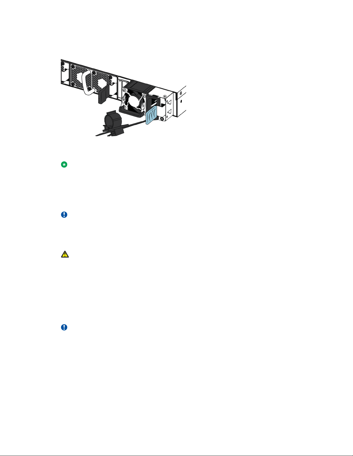
Figure 1: AC power supply
The AC power supplies use an IEC 60320 C16 AC power cord connector. The AC power cord is in
close proximity to the hot air exhaust, and supports high operating temperatures.
Figure 2: IEC 60320 C16 connector
The following table describes the regulatory AC power specifications for the VSP 7200 switches.
Note that regulatory power specifications are based on the maximum rated capacity of the power
supplies and are not based on typical power consumption, which is typically lower.
Table 3: 460 W AC power specifications
7254XSQ
Input Current: 460 W/90 or 460/180 @88%,
5.8 A maximum at low input voltage
2.9 A maximum at high input voltage
Input Voltage (rms): 100–127 V or 200–240 V, 47–63 Hz (50–60 Hz
nominal)
Power Consumption: 460 W maximum
Thermal Rating: 1570 BTU/Hr maximum
Inrush Current: 55 A maximum
January 2015 Installation Job Aid for Avaya Virtual Services Platform 7200 Series 7
7254XSQ
Turn on Condition: 5–400 ms delay after application of AC power
Important:
The output rise time, from 10 to 90 percent, is 70 ms maximum and monotonic under all defined input
and output conditions.
Efficiency: 85 percent minimum
Table 4: 800 W AC power specifications
7254XTQ
Input Current: 9.9–4.79 A
Input Voltage (rms): 100–240 V, 47–63 Hz
Power Consumption: 800 W maximum
Thermal Rating: 2730 BTU/Hr maximum
Inrush Current: 40 A maximum
Turn on Condition: 1 second maximum after application of AC power
Important:
The output rise time, from 10 to 90 percent, is 50 ms maximum and monotonic under all defined input
and output conditions.
Efficiency: 70 percent minimum
AC power cord specifications
To connect AC power to the switch, you need an appropriate AC power cord as described in the
following table, also see the following table for plug specifications.
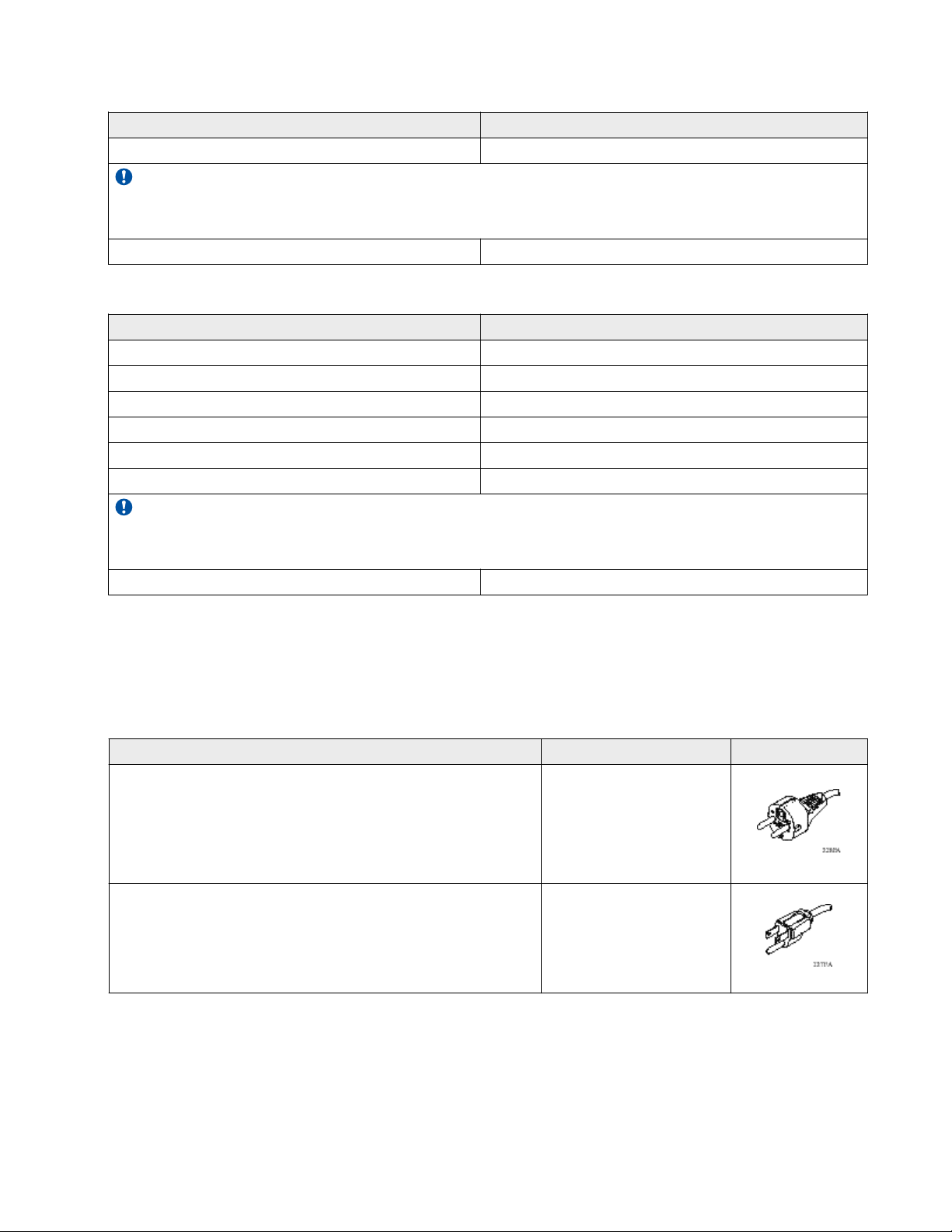
Table 5: International power cord specifications
Country and Plug Specification Specifications Typical Plug
Continental Europe:
• CEE7 standard VII male plug
• Harmonized cord (HAR marking on the outside of the cord
jacket to comply with the CENELEC Harmonized
Document HD-21)
United States of America, Canada, and Japan:
• NEMA5-15P male plug
• UL-recognized (UL stamped on cord jacket)
• CSA-certified (CSA label secured to the cord)
• 220 or 230VAC
• 50 Hz
• Single phase
• 100 or 120VAC
• 50–60 Hz
• Single phase
January 2015 Installation Job Aid for Avaya Virtual Services Platform 7200 Series 8

Country and Plug Specification Specifications Typical Plug
United Kingdom:
• 240VAC
• BS1363 male plug with fuse
• Harmonized cord
Australia:
• AS3112-1981 male plug
Danger:
Using power cords with a proper grounding path
Use only power cords that have a grounding path. Without a proper ground, a person who
touches the switch is in danger of receiving an electrical shock. Lack of a grounding path to the
switch can result in excessive emissions.
Installing a DC power supply
Important:
Avaya does not support installing a combination of AC-input and DC-input power supplies in the
same chassis.
• 50 Hz
• Single phase
• 240VAC
• 50 Hz
• Single phase
The VSP 7200 Series supports two field-replaceable 800 W DC power supplies. One comes with
the switch and you can install a second power supply to provide redundancy and load sharing.
There are two power supply slots (PSU1 on the left side and PSU2 on the right).
Important:
Refer to the following part numbers to ensure that you install the correct power supplies in your
switch. Both the VSP 7254XSQ (fiber switch) and the VSP 7254XTQ (copper switch) use the
same DC power supply models:
• EC720500B-E6 — 800 W DC POWER SUPPLY BACK2FRONT COOLING
• EC8005001-E6 — 800 W DC POWER SUPPLY FRONT2BACK COOLING
• If you only have one power supply, you can install it in either PSU1 or PSU2.
• If you install a second power supply, neither one acts as a primary power supply. The two
power supplies load share equally.
Before you begin
Remove the power cord before installing or removing the power supply.
Note:
The design of the latch mechanism that secures the power supply enforces this safety practice.
January 2015 Installation Job Aid for Avaya Virtual Services Platform 7200 Series 9

Procedure
1. If there is a power supply cover, remove it and save for possible future use. To remove the
cover, push the tab on the spring latch to the left and pull on the extraction handle.
Important:
If you only have one power supply installed, the other slot must be covered to ensure
proper ventilation. If a power supply fails, replace it as soon as you can but leave it in
place until you do. Leaving a power supply slot unpopulated impairs the ability of the
fans to cool the chassis.
2. Slide the power supply into the slot.
3. Verify that the power supply is fully seated in the slot. The spring latch should engage and
return to its original position.
January 2015 Installation Job Aid for Avaya Virtual Services Platform 7200 Series 10
Loading...