


IP Office 3.0
Avaya IP Office 3.0, 4601, 4602, 4602SW, 4606 Installation Manual
...
IP Office 3.0
Avaya IP Phone Installation
Issue 10b (26th January 2005)


Avaya IP Phone Installation Page iii
IP Office 3.0 Issue 10b (26th January 2005)
Table of Contents
Avaya IP Phones ........................................................................................................................ 5
Introduction................................................................................................................................................. 5
What's New in 3.0....................................................................................................................................... 6
Installation Requirements ........................................................................................................................... 7
Network Assessment.................................................................................................................................. 8
Voice Compression Channels .................................................................................................................... 9
QoS ............................................................................................................................................................ 9
Potential VoIP Problems........................................................................................................................... 10
Power Supply Options .............................................................................................................................. 11
Spare Wire Power Options .................................................................................................................. 11
802.3af Power over Ethernet Options.................................................................................................. 12
User PC Connection................................................................................................................................. 12
Installation ................................................................................................................................ 13
1. Preparation ........................................................................................................................................... 13
4601 and 5601 Installation ....................................................................................................................... 14
1a. Creating a 46xxsettings.txt File .......................................................................................................... 14
2. Phone Connection ................................................................................................................................ 15
3a. DHCP Address Installation ................................................................................................................. 15
3b. Static Address Installation .................................................................................................................. 16
4. Phone Registration ............................................................................................................................... 17
5. Extension & User Setup ....................................................................................................................... 18
Manually Creating Extensions .................................................................................................................. 19
Phone Security ......................................................................................................................................... 20
Listing Registered Phones........................................................................................................................ 20
Static Administration............................................................................................................... 21
Static Administration Options ................................................................................................................... 21
Entering Data for Administrative Options ................................................................................................. 21
QoS Option Settings................................................................................................................................. 22
Secondary Ethernet (Hub)/IR Interface Enable/Disable ........................................................................... 22
Appendix A: Miscellaneous .................................................................................................... 23
Error Messages ........................................................................................................................................ 23
View Administrative Details ...................................................................................................................... 24
Reset System Values ............................................................................................................................... 25
Self-Test Procedure.................................................................................................................................. 25
Site Specific Option Number .................................................................................................................... 26
Automatic Gain Control ............................................................................................................................ 26
Appendix B: IP Telephone Files ............................................................................................. 27
IP Telephone Files.................................................................................................................................... 27
The 46XX Upgrade Script File.................................................................................................................. 28
The 46XX Settings Script File................................................................................................................... 29
46XX Settings ...................................................................................................................................... 30
Appendix C: Scenarios for the Restart Process ................................................................... 31
4600 Restart Scenarios ............................................................................................................................ 31
Boot File Needs Upgrading ...................................................................................................................... 32
No Application File or Application File Needs Upgrading .........................................................................33
Correct Boot File and Application File Already Loaded ............................................................................ 33
Appendix D: Infrared Dialing................................................................................................... 35
Infrared Dialing ......................................................................................................................................... 35
Enabling the IR Port ................................................................................................................................. 36
Dialing Phone Numbers............................................................................................................................ 37
Palm Organizer .................................................................................................................................... 37
Psion Revio.......................................................................................................................................... 37

Table Of Contents
Avaya IP Phone Installation Page iv
IP Office 3.0 Issue 10b (26th January 2005)
Windows Pocket PC ............................................................................................................................ 38
Beaming Files During a Call ..................................................................................................................... 38
Palm Organizer .................................................................................................................................... 38
Appendix E: Alternate DHCP Setup........................................................................................ 39
Alternate DHCP Servers for Avaya IP Phone Installation ........................................................................ 39
Using Windows 2000 Server .................................................................................................................... 40
1. Checking for DHCP.......................................................................................................................... 40
2. Windows 2000 DHCP Setup for Avaya IP Phones .......................................................................... 40
Alternate Options...................................................................................................................................... 42
Appendix F: WML Operation................................................................................................... 43
WML Server Setup ................................................................................................................................... 43
What WML is Supported ...................................................................................................................... 43
Testing WML Browsing Using Xitami ....................................................................................................... 44
1. Introduction ...................................................................................................................................... 44
2. Installing the Web Server................................................................................................................. 44
3. Configuring the Xitami Web Server for WAP ................................................................................... 45
4. Installing Sample WML Pages ......................................................................................................... 46
Setting the Home Page ............................................................................................................................ 47
Apache Web Server WML Configuration.................................................................................................. 48
Microsoft IIS Web Server WML Configuration.......................................................................................... 48
Open URL Entry ....................................................................................................................................... 49
Case 1. Input Box Followed by an Anchor Tag.................................................................................... 49
Case 2. Input Box Followed by an A Tag............................................................................................. 49
Case 3. Input Box Followed by a Submit Button.................................................................................. 49
Case 4. Input Box Followed by an Anchor Tag Where the Anchor Tag Already Displays HTTP:// ..... 49
Appendix G: 3616/3626 Installation........................................................................................ 51
3616/3626 Spectralink Installation............................................................................................................ 51
Related Documents ............................................................................................................................. 51
Configuration ............................................................................................................................................ 52
System Configuration........................................................................................................................... 53
Installation and Configuration .............................................................................................................. 54
Sample Set-up ..................................................................................................................................... 55
Glossary.................................................................................................................................... 57
Index.......................................................................................................................................... 59
Avaya IP Phone Installation Page 5
IP Office 3.0 Issue 10b (26th January 2005)
Avaya IP Phones
Introduction
This guide covers the installation of 4600 Series and 5600 Series of Avaya IP phones on the IP Office.
Currently the following Avaya IP phones are supported on IP Office 3.0:
• 4601, 4602, 4602SW, 4606, 4610SW, 4612, 4620, 4620SW, 4624.
• 5601, 5602, 5602SW, 5610SW, 5620, 5620SW.
• 3616 and 3626 wireless phones
(See Appendix G for installation of these phones.)
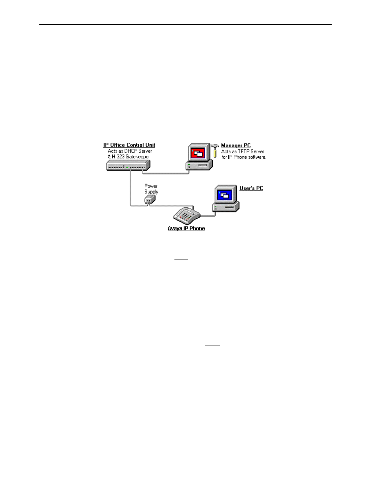
The diagram below shows the simplest installation scenario, suitable when only a few Avaya IP phones
are being installed.
Please note the following:
• IP Phone Software Version
Avaya IP phones on an IP Office system must
use the IP Phone software supplied on the IP
Office Administrator Applications CD. Versions of IP Phone software from other sources may not
be intended for use with or tested with IP Office.
• DHCP versus Static IP Installation
Though static IP installation of Avaya IP telephones is possible, installation using DHCP is
strongly recommended
. The use of DHCP eases both the installation process and future
maintenance and administration. In addition, following a boot file upgrade, all static address
settings are lost and must be re-entered.
• Network Assessment
High quality voice transmission across an IP network requires careful assessment of many
factors. We strongly recommend that Avaya IP telephone installation is only done by installers
with VoIP experience. The whole customer network must
be assessed for it suitability for VoIP
before installation. For further details see Network Assessment.
• Full information on LAN administration and configuration is contained in the Avaya documents
"4600 Series IP Telephone LAN Administrator's Guide" (Avaya Com Code 555-233-507).

IP Office IP Phone Installation Manual
Avaya IP Phone Installation Page 6
IP Office 3.0 Issue 10b (26th January 2005)
What's New in 3.0
The main changes to IP phone support in IP Office 3.0 is the addition of support for several new phones.
These are:
• Avaya 4600 Series IP Phones
The following phones in the 4600 Series are now supported on IP Office.
• 4601
A basic model IP phone with no display and only two programmable feature keys.
• 4610SW
Similar to the existing 4620SW with 24 programmable display features but has only 6
display keys for accessing those features.
• Avaya 5600 Series IP Phones
This is a new range of IP phones introduced for use on IP Office only. These phones are not
supported on any other Avaya telephone system. The features of the phones in this range are the
same as their equivalent 4600 Series models. The 5600 Series IP phones are:
• 5601
• 5602
• 5602SW
• 5610SW
• 5620SW
• EU24 Add-On
This phone add-on is now supported for use on IP Office. It can be used with 4610SW, 4620,
4620SW, 5610SW and 5620SW phones to provide an additional 24 programmable feature keys.
The add-on connects directly to the phone.

Avaya IP Phones
Avaya IP Phone Installation Page 7
IP Office 3.0 Issue 10b (26th January 2005)
Installation Requirements
To install an Avaya IP phone onto IP Office, the following items are required:
• Extension Number and User Details
A full listing of the planned extension number and user name details is required. The planned
extension number must be unused and is requested by the phone during installation.
• Power Supply:
Each phone requires a power supply. Avaya IP phones do not draw power from the telephone
switch. A number of options exist for how power is supplied to the phones, see Power Supply
Options.
• LAN Socket:
A 10/100Mbps RJ45 Ethernet LAN connection point is required for each phone.
• Category 5 Cabling
All LAN cables and LAN cable infrastructure used with Avaya IP phones must be
Category 5
cabling.
• LAN Cables:
Check that an RJ45 LAN cable has been supplied with the Avaya IP phone for connection to the
power unit. You will also need an additional RJ45 LAN cable for connection from the power unit
to the customer LAN.
• A further RJ45 LAN cable can be used to connect the user's PC to the LAN via the IP
telephone [not supported on 4601, 4602, 5601 and 5602 IP phones].
• Voice Compression Module:
The IP Office Control Unit must have voice compression channels available. The number of voice
compression channels limits the number of simultaneous VoIP calls:
• On Small Office Edition units, voice compression channels are pre-built into the unit.
• On all other control units, voice compression channels are provided by fitting a Voice
Compression Module. See Voice Compression
• DHCP Server:
The IP Office Control Unit can perform this role. If another DHCP server already exists this may
be able to do DHCP for the Avaya IP phones, see Alternate DHCP Servers. Static IP addressing
can also be used if required but is not recommended.
• TFTP Server:
A PC running the IP Office Manager application can perform this role. The TFTP server is only
required during IP telephone installation and maintenance.
• H323 Gatekeeper:
The IP Office Control Unit can perform this role unless a third party gatekeeper already exists.
• IP Office Manager PC:
A PC running Manager is required for IP Office Control Unit configuration changes. This PC
should have a static IP address.
• IP Telephone Software:
The software for IP telephone installation is supplied on the IP Office Administrator Applications
CD and installed into the Manager program folder during Manager installation.
• Licence Keys:
Avaya IP telephones do not need
a licence key entered on the system. An IP End-Points license
is only required for non-Avaya IP phones.

IP Office IP Phone Installation Manual
Avaya IP Phone Installation Page 8
IP Office 3.0 Issue 10b (26th January 2005)
Network Assessment
Current technology allows optimum network configurations to deliver VoIP with voice quality close to that
of the Public Switched Telephone Network (PSTN). However few networks are optimum and so care
should be taken assessing the VoIP quality achievable across a customer network.
Not every network is able to carry voice transmissions. Some data networks have insufficient residual
capacity for even compressed voice traffic. In addition, the usual approach of developing data networks
by integrating products from many vendors makes it necessary to test all the network components for
compatibility with VoIP traffic.
It is assumed that a network assessment has been performed, with or without the assistance of Avaya,
before attempting to install VoIP. You must do this in order to have a high degree of confidence that the
existing data network has the capacity to carry voice packet traffic and is compatible with the required
technology.
A network assessment would include a determination of the following:
• A network audit to review existing equipment and evaluate its capabilities, including its ability to
meet planned voice and data needs.
• A determination of network objectives, including the dominant traffic type, choice of technologies,
and setting voice quality objectives.
The assessment should leave you confident that the implemented network will have the capacity for the
foreseen data and voice traffic, and can support H.323, DHCP, TFTP and jitter buffers in H.323
applications.
It is important to distinguish between compliance with the minimal VoIP standards and support for QoS
which is needed to run VoIP on your configuration.

Avaya IP Phones
Avaya IP Phone Installation Page 9
IP Office 3.0 Issue 10b (26th January 2005)
Voice Compression Channels
IP Office Voice Compression channels are used when a VoIP call goes between a device on the IP data
network (LAN or WAN) and a device on the TDM telephony interface, for example a DS, DT or POT
extension or a non-IP trunk.
Calls between IP extensions do not normally need a VCM channel once the call is connected but do use
VCM channels for call signalling tones, music-on-hold, etc.
The VCM channels automatically use either G.723 (6k3) or G.729a (8k) compression Codecs and
provide echo cancellation required for high latency circuits. Avaya IP telephones support G.711, G.729a
and G.729b, thus G.729b is normally auto-negotiated when these phones are used on IP Office.
The number of available voice compression channels in an IP Office Control Unit can limit the number of
VoIP calls. On IP401, IP403, IP406, IP406 V2 and IP412 control units, channels are added by installing
VCM modules. The type and number of VCM modules that can be installed depends on the control unit
type.
• IP401: Support a single VCM 5 module.
• IP403: Support a single VCM 5, 10 or 20 module.
• IP406 V1: Support a single VCM 5, 10 or 20 module.
• IP406 V2: Supports a single VCM 5, 10, 20 or 30 module.
• IP412: Supports any two modules from VCM 5, 10, 20 or 30, ie. up to 60 voice compression
channels.
• Small Office Edition: Supplied with either 3 or 16 VCM channels pre-built into the unit. These
cannot be upgraded.
QoS
When transporting voice over low speed links it is possible that normal data packets (1500 byte packets)
can prevent or delay voice packets (typically 67 or 31 bytes) from getting across the link. This can cause
a very unacceptable speech quality.
Thus it is vital that the traffic routers in the network have some form of Quality of Service mechanism
(QoS). QoS routers are essential to ensure low speech latency and to maintain sufficient audible quality.
IP Office supports the DiffServ (RFC2474) QoS mechanism. This is based upon using a Type of Service
(ToS) field in the IP packet header. On its WAN interfaces, the IP Office use this to prioritizes voice and
voice signalling packets. It also fragments large data packets and where supported provides VoIP
header compression to minimize the WAN overhead.
Note that the IP Office does not perform QoS for its Ethernet ports including the WAN Ethernet port on
the Small Office Edition.

IP Office IP Phone Installation Manual
Avaya IP Phone Installation Page 10
IP Office 3.0 Issue 10b (26th January 2005)
Potential VoIP Problems
It is likely that any fault on a network, regardless of its cause, will initially show up as a degradation in the
quality of VoIP operation. This is regardless of whether the fault is with the VoIP telephony equipment.
Therefore in installing a VoIP solution, you must be aware that you will become the first point of call for
diagnosing and assessing customer network issues.
Potential Problems
• End-to-End Matching Standards:
VoIP depends upon the support and selection of the same voice compression, header
compression and QoS standards throughout all stages of the calls routing. The start and end
points must be using the same compression methods. All intermediate points must support
DiffServ QoS.
• Avoid Hubs:
Hubs introduce echo and congestion points. If the customer network requires LAN connections
beyond the capacity of the IP Office Control Unit itself, Ethernet Switches should be used. Even if
this is not the case, Ethernet Switches are recommended as they allow traffic prioritization to be
implemented for VoIP devices and for other device such as the Voicemail Server PC.
• Power Supply Conditioning, Protection & Backup:
Traditional telephone systems provide power to all their attached telephone devices from a single
source. In a VoIP installation, the same care and concern that goes into providing power
conditioning, protection and backup to the central telephone system must now be applied to all
devices on the IP network.
• Multicasting:
In a data only network, it is possible for an incorrectly installed printer or hub card to multicast
traffic without that fault being immediately identified. On a VoIP network incorrect multicasting will
quickly affect VoIP calls and features.
• Duplicate IP Addressing:
Duplicate addresses is a frequent issue.
• Excessive Utilization:
A workstation that constantly transmits high traffic levels can flood a network, causing VoIP
service to disappear.
• Network Access:
An IP network is much more open to users connecting a new devices or installing software on
existing devices that then impacts on VoIP.
• Cabling Connections:
Technically VoIP can (bandwidth allowing) be run across any IP network connection. In practice
Cat5 cabling is essential
.
Avaya IP Phones
Avaya IP Phone Installation Page 11
IP Office 3.0 Issue 10b (26th January 2005)
Power Supply Options
Avaya IP telephones can be powered using a number of options. The main characteristic is to power the
phones either via the spare wires in the network cable or on the same wires as the data signals (802.3.af
Power over Ethernet).
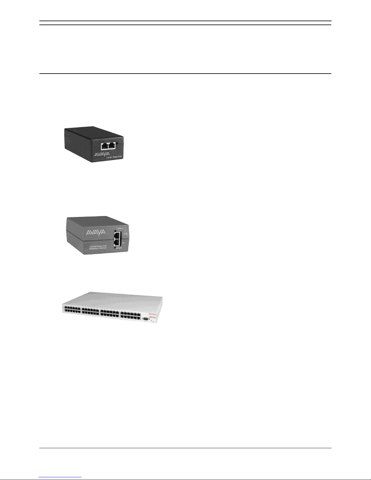
Spare Wire Power Options
The following power supplies use the spare pin 7 & 8 connections in the CAT5 network cable.
• Avaya 1151B1 Power Supply Unit (PSU)
A power supply unit for a single Avaya IP phone. Has a LINE port for the LAN cable from the IP
Office, and a PHONE port for the LAN cable to the Avaya IP phone. Power into the PSU requires
a 90 to 264V AC, 47 to 63HZ mains supply. A green LED indicates when power is available.
• Avaya 1151B2 Power Supply Unit
Same as the 1151B1 above but with integral battery backup. When AC mains supply is removed,
the battery will power the Avaya IP telephone for between 8 hours at light load (2 Watts) and 15
minutes at full load (20 Watts). A green LED indicates when power is available. A yellow LED
indicates when the backup is charging. The green LED flashes when the phone is running from
the backup battery.
• Avaya 1152A1 Power Distribution Unit (Mid-Span Power Unit)
This is a 1U high 19-inch rack mountable unit. It can support up to twenty-four Avaya IP
telephones. It provides 24 RJ45 LAN data in ports and 24 RJ45 LAN data and power out ports. It
can supports a maximum of 200 Watts or a peak of 16.8 Watts per port.
IP Office IP Phone Installation Manual
Avaya IP Phone Installation Page 12
IP Office 3.0 Issue 10b (26th January 2005)
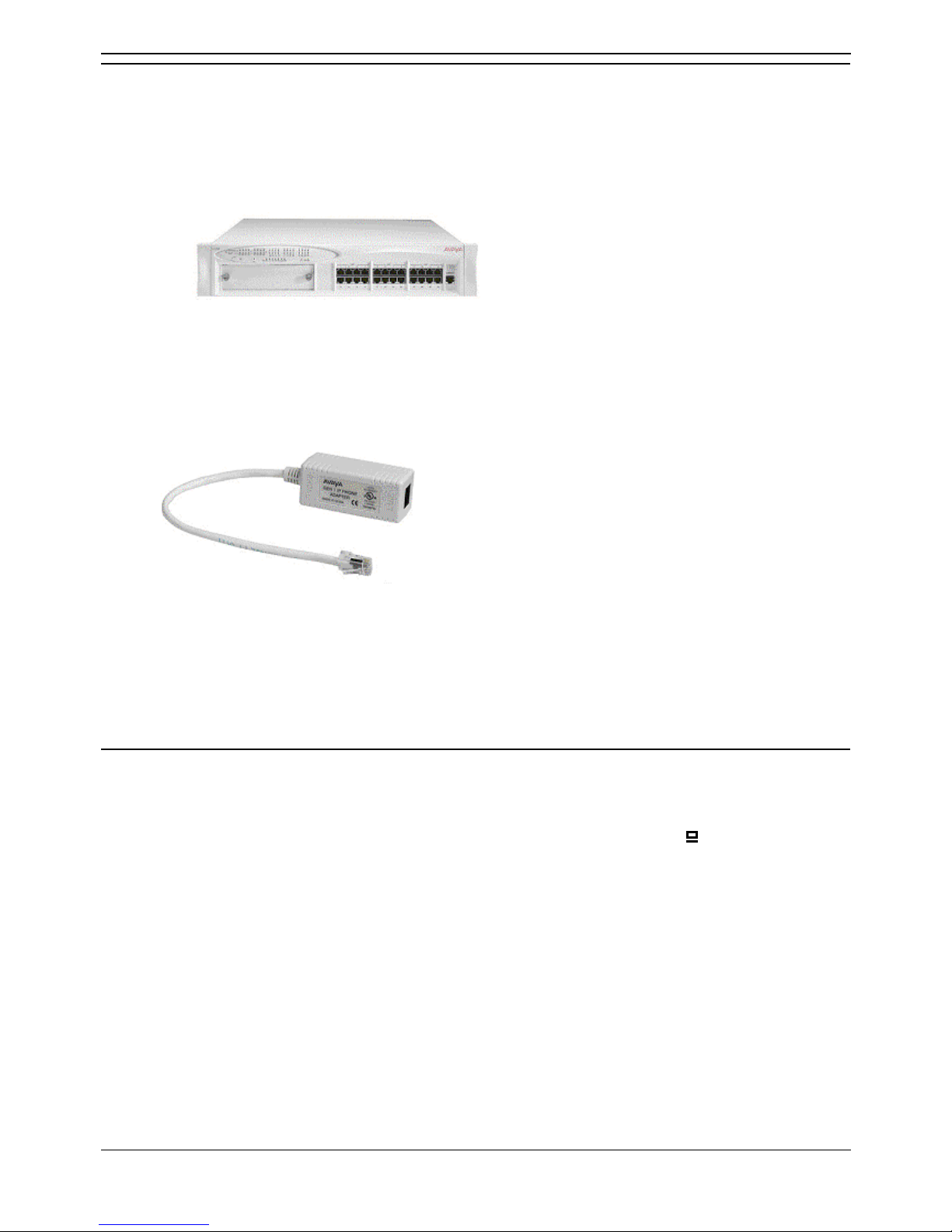
802.3af Power over Ethernet Options
IEEE 802.3af is a standard, commonly known as Power over Ethernet (PoE), that allows network
devices to receive power via the network cable. All the Avaya IP telephones supported on IP Office also
support this standard.
Power of Ethernet (POE) Switch
The Avaya P333T-PWR Switch is a Ethernet LAN switch which also provides PoE input for
up to 24 devices including Avaya IP phones.
• IP Phone Inline Adaptor
This adaptor allows 4602, 4602SW and 4620 IP phones and equivalent 5600 Series models to
be powered from a Cisco Catalyst power blade. Up to 24 Avaya IP phones have been supported
on a single power blade using these adaptors. Note however that the phones do not provide the
Catalyst switch with information on their power requirements and future changes to Catalyst
switch software may affect operation
*4606, 4612 and 4624
Applies to GEN2 and later models. The GEN of these phones can be determined from the label on the
base of the phone. The label text giving the phone's type, for example 4624D, is followed two digits
which give its generation (GEN) number, for example 4624D01. GEN1 4612 and 4624 phones can be
Ethernet powered using an Avaya 30A Switch Upgrade Base unit.
User PC Connection
To simplify the number of LAN connections from the user's desk, it is possible to route their PC Ethernet
LAN cable via some Avaya IP phones.
The LAN cable should be connected from the PC to the socket with a PC symbol (
) at the back of the
Avaya IP Phone.
The PC's network configuration does not need to be altered from that which it previously used for direct
connection to the LAN.
This is not supported on the 4601, 4602, 5601 and 5602 Avaya IP phones.

Avaya IP Phone Installation Page 13
IP Office 3.0 Issue 10b (26th January 2005)
Installation
1. Preparation
Check the following before beginning installation. These are essential steps and installation will fail if
they are not followed.
1. Manager PC Static Address:
Ensure that the Manager PC has been given a static IP address.
2. Voice Compression Module:
The IP Office Control Unit must be fitted with a Voice Compression Module (VCM). For an Small
Office Edition control unit a number of voice compression channels are preinstalled on the
motherboard.
• Start the IP Office Monitor application. The initial lines of Monitor output include the item
VCOMP= which will state the number of voice compression channels installed in the
control unit.
3. Control Unit Settings:
Using the Manager Application, open the configuration and select the System form. Check the
following:
a. System Name:
In the System tab ensure that a Name for the Control Unit has been entered.
b. TFTP Server IP Address:
In the LAN1 tab, enter the IP address of the Manager PC as the TFTP Server IP
Address.
c. Gatekeeper Settings:
In the Gatekeeper tab, ensure that Gatekeeper Enabled and Auto-create Extn Enable
are both selected. If you do not want to install using auto-create extension, you will need
to configure the required extensions and user at this stage, see Manually Creating
Extensions.
d. If you have made any changes, upload the new configuration to the Control Unit.
e. Within Manager, select File | Preferences and ensure that the address is
255.255.255.255, otherwise TFTP will not work.
4. IP Phone Software:
The software for IP telephone installation is supplied on the IP Office Administration CD. The files
are copied into the Manager folder during installation of the Manager application.
• An additional file (46xxsettings.txt) is also required. See 1a. Creating a 46xxsettings.txt
File .
5. Manager and TFTPLog:
Leave Manager running. It is also useful to have Manager's TFTP Log visible (select View |
TFTPLog). This will display the progress of file requests.
6. Extension Number and User Name Details
A full listing of the planned extension number and user name details is required. The planned
extension number must be unused and is requested by the phone during installation.

IP Office IP Phone Installation Manual
Avaya IP Phone Installation Page 14
IP Office 3.0 Issue 10b (26th January 2005)
4601 and 5601 Installation
These two IP phones do not have a display screen to assist with installation and diagnostics.
The only method of installation supported is DHCP and this means the preparation requirements listed in
1. Preparation are essential for successful installation.
During installation the phone obtains and stores the IP addresses of the Call Server (the IP Office
gatekeeper) and the TFTP server (the Manager PC). Currently we are not aware of any field method for
resetting these values in order to move a 4601 or 5601 to a different IP Office system.
1a. Creating a 46xxsettings.txt File
During installation, the Avaya IP phones request software by downloading and following instructions
within the 46xxupgrade.scr file (see The 46XX Upgrade Script File). This file is provided as part of the
IP Office Manager software and should normally not be changed.
The last lines of the 46xxupgrade.scr file instruct the phone to request the file 46xxsettings.scr or
46xxsettings.txt. If present, that file is downloaded and used to set customer site specific options for the
Avaya IP phones.
If not present:
1. Using Windows Notepad or any other plain text editing tool, create a text file called
46xxsettings.txt.
2. Edit the file to contain the following:
## 4600 Site Specific Settings
SET L2Q 2
## END OF FILE
• The SET L2Q 2 is recommended for IP Office operation.
• For other settings, see The 46XX Settings Script File.
• If 4610 or 4620 phones are being installed, this file is used to set the home page for their
WML web browsing, see WML Server Setup.
3. Place this file in the same folder as the 4600 Series IP Phone software, normally this is the same
folder as the Manager application.

Installation
Avaya IP Phone Installation Page 15
IP Office 3.0 Issue 10b (26th January 2005)
2. Phone Connection
1. Follow the steps in 1. Preparation. If those steps are not followed installation will fail.
2. Connect the network LAN cable to the data in socket of the power supply being used for the
phone.
• On 1151A1/1151A2 Power Supply Units the socket is marked LINE.
• On the 1152A1 Power Supply Unit the lower sockets are data in.
3. Connect the LAN cable supplied with the IP telephone from the power supplies data and power
out socket to the socket with a LAN port symbol (
) at the back of the IP telephone.
• On 1151A1/1151A2 Power Supply Units the socket is marked PHONE.
• On the 1152A1 Power Supply Unit the upper sockets are data and power.
4. The phone's message indicator should glow red for a few seconds. The phone will then begin its
software loading.
5. After a short delay the phone should display Initializing and then Loading…. The loading phase
may take a few minutes.
• If the phone displays No Ethernet check the connection to the LAN.
6. The phone displays DHCP and a timer. It is attempting to obtains IP address information from a
DHCP server on the network.
• To continue with DHCP address installation
See 3a. DHCP Address Installation
• To switch to static address installation
Press * whilst DHCP is shown if you want to enter static address installation. See 3b.
Static Address Installation. This is not supported for the 4601 and 5601.
3a. DHCP Address Installation
1. Having connected the phone (see 2. Phone Connection) it eventually displays DHCP and a timer.
• On 4601 and 5601 phones, initially all lamps will be on as the phone initializes. All lamps
on with the button a lamp flashing indicates attempting DHCP.
2. After a few seconds it should complete DHCP negotiation. If the timer reaches more than 60
seconds, you should suspect an error in either the network or DHCP operation.
3. The phone requests the 46xxupgrade.scr file from the TFTP server (Manager). This should be
visible in the Manager's TFTP Log and on the phones display.
• On 4601 and 5601 phones, all lamps will be on with both the button a and button b lamps
flashing whilst TFTP is attempted and occurring.
4. The phone now requests additional files according to the instructions it found in the
46xxupgrade.scr file. The phone will go through a cycle of requesting files, loading files and then
transferring the files into its flash memory.
5. Following file loading the phone displays Ext. =. See 4. Phone Registration.

IP Office IP Phone Installation Manual
Avaya IP Phone Installation Page 16
IP Office 3.0 Issue 10b (26th January 2005)
3b. Static Address Installation
WARNING: Static addressing is only necessary when a DHCP server is unavailable. For ease of
maintenance and installation it is strongly recommended that a DHCP server is installed and that
static addressing avoided. Following a boot file upgrade static address information must be
reinstalled.
This process is not supported on 4601 and 5601 phones.
1. Follow the steps in 2. Phone Connection.
2. Start manual address programming by doing either of the following:
• When DHCP is shown on the phone press *.
• While the phone is on-hook and idle, press the following key sequence; Hold 2 3 3 7 #
(Hold A D D R #).
3. For details of entering data such as back spacing see Entering Data for Administrative Options.
4. The phone displays Phone=. This is the phone's IP address. Press # to accept the current value
or enter a value and then press #.
• If entering a new value, use the * key to enter a '.' character between digits. Use the < key
to backspace if necessary.
5. The phone displays CallSv=. This is the address of the Gatekeeper. Press # to accept the
current value or enter a value and then press #.
• If the IP Office is acting as the Gatekeeper, then this is the IP address of the IP Office
Control Unit (LAN1).
6. The phone displays CallSvPort=. This is the Gatekeeper transport layer port number, a value
between 0 and 65535. Press # to accept the current value or enter a value and then press #.
• For IP Office Gatekeeper operation, enter 1719 and then press #.
7. The phone displays Router=. This is the address of its default gateway. Press # to accept the
current value or enter a value and then press #.
• For IP Office operation, this is the IP address of the IP Office Control Unit.
8. The phone displays Mask=. This is its IP Mask (also called sub-net mask). Press # to accept the
current value or enter a value and then press #.
• This should match the IP mask set for the IP Office Control Unit.
9. The phone displays FileSv=. This is the address of the TFTP server. Press # to accept the
current value or enter a value and then press #.
• This should match the IP address of the PC running the Manager application.
10. The phone displays 802.1Q=auto. Press * twice to change the setting to 802.1Q=off, then press
# to accept this value.
11. The phone displays VLAN ID=0. Press # to accept this value.
12. The phone displays Save new values?. Press # to save the new values you have entered. New
values being saved is shown, the phone then resets.
13. Installation is now the same as from Step 3 of DHCP Address Installation, see 3a. DHCP
Address Installation.
Note: If a new boot program is downloaded from the TFTP server after you enter static addressing
information, you will need to reenter your static addressing information.

Installation
Avaya IP Phone Installation Page 17
IP Office 3.0 Issue 10b (26th January 2005)
4. Phone Registration
The following will also occur following any power loss to the telephone.
1. Following file loading, the phone displays Ext. =. Enter the extension number you want applied to
the phone and press #.
• On 4601 and 5601 phones, this stage is indicated by the lamp at the top of the phone and
on the MESSAGES button flashing 0.5 seconds on/off.
• If not using auto-create extension, the extension number selected must be a pre-configure
VoIP extension, see Manually Creating Extensions.
• If the phone has been previously installed and has not been reset it will display the
extension number that it last used.
• Wrong Set Type is displayed if you try to use the extension number of an existing non-IP
extension.
2. The phone displays Password =.
• If using auto-create extension for a new extension, just enter any number and press #.
Any digits entered for a password here are not validated or stored.
• If not using auto-create extension for a new extension, enter the User's Login Code set in
the IP Office Manager.
• During subsequent phone restarts, even though the password is requested, it will only be
validated if the phone's extension number is changed.
3. On display phones, the phone display the time, date and then its extension number.
4. Test that you can make and receive calls at the extension.

IP Office IP Phone Installation Manual
Avaya IP Phone Installation Page 18
IP Office 3.0 Issue 10b (26th January 2005)
5. Extension & User Setup
If installing using auto-create extensions, you can now use IP Office Manager to open the control unit's
configuration and alter the extension and user settings for the telephone.
The following process covers the minimum extension and user setup required.
1. In Manager, click on
to receive the system's configuration.
2. Click on
Extension to display the list of existing extensions.
3. The
icon indicates VoIP extensions. A new extension will have been created matching the
extension number entered above. In the extension's VoIP tab, the Compression Mode default is
Automatic Selection.
4. Click on
User to display the list of existing users. In the list of users, a new user will have been
created matching the VoIP extension number above.
5. Double-click on the Avaya IP telephone extension user to display their settings.
6. In the User tab set the user Name and Full Name as required.
7. Click the Digital Telephony tab.
8. For the first three buttons, we recommend that you click on the Action field and select
Appearance | Call.
9. Click OK.
10. When all new IP phone extension have been setup, click on
to send the new configuration
back to the system. Set the Reboot Mode to Immediate or When Free as Extension changes
cannot be merged.

Installation
Avaya IP Phone Installation Page 19
IP Office 3.0 Issue 10b (26th January 2005)
Manually Creating Extensions
If installing without auto-create extensions enabled, then VoIP extensions and associated users must
first be created in IP Office Manager.
The procedure below covers the minimum required to create a VoIP extension and associated user.
Further customization is as per any extension and user.
1. In Manager, click on
to receive the system's configuration.
2. Click on
Extension in the left-hand panel to display the list of existing extensions. Right-click
on the right-hand panel and select New.
3. In the Extn tab, set the following:
• Extension ID:
For non-VoIP extension this number is assigned automatically. For a VoIP extension
enter any number so long as it is unique, ie. not already used by another extension.
• Extension:
Enter the extension number to assign to the telephone. Again this must be unique.
4. In the VoIP tab, the required IP Address and/or MAC Address can be set if required for additional
phone security. See Phone Security.
5. Click OK to add the new extension.
6. Click on
User in the left-hand panel to display the list of existing users. Right-click on the right-
hand panel and select New.
7. In the User tab set the following:
• Name:
Enter a name for the extension user. The name must be unique. If voicemail is in use, this
name will be used as the basis for a new mailbox with matching name.
• Extension:
This must match the extension number set in the VoIP extension created above.
8. Click on the Digital Telephony tab.
9. For the first three buttons, we recommend that you click on the Action field and select
Appearance | Call.
10. Click on OK.
11. When all new IP phone extension being added have been setup, click on
to send the new
configuration back to the system. Set the Reboot Mode to Immediate or When Free as
Extension changes cannot be merged.

IP Office IP Phone Installation Manual
Avaya IP Phone Installation Page 20
IP Office 3.0 Issue 10b (26th January 2005)
Phone Security
There are a number of methods by which additional security can be implemented to ensure that on IP
phone does not adopt the identity of another.
• Disable Auto-Create Extension
Following installation, disabling Auto-Create Extn Enabled in the IP Office Manager System |
Gatekeeper tab stops new IP devices from assigning themselves as new extensions.
• Restrict the IP or MAC Address
Entering either of these values in the Extension's VoIP tab will restrict usage to that address or
device. The MAC address of an Avaya IP Telephone is printed on a label on the base of the
phone.
• Set a User Login Code
If a user Login Code is set, then any other IP device trying to log on as that extension must also
enter the correct login code. Note that if a login code is set, the user can use hot desk to log off
and log on elsewhere.
Listing Registered Phones
Using TFTP, a list can be obtained from the IP Office system of all the registered RAS users which
includes IP phones. For example:
Extn2602,2602,192.168.42.2,1720
ains600,2600,192.168.42.10,1026
Extn2601,2601,192.168.42.4,1720
New,2702,192.168.42.200,1720
1. In Windows select Start | Run and enter cmd for the Windows command line interpreter.
2. If necessary use cd commands to select the directory into which you want the list placed as the
current directory.
3. Enter
tftp -i xxx.xxx.xxx.xxx get nasystem/h323_ras_list yyyyyyyy.txt where:
•
xxx.xxx.xxx.xxx is the IP address of the IP Office system control unit.
• yyyyyyy.txt is the name of a text file that doesn't already exist in that directory..
4. The TFTP command will confirm when the file has been successfully transferred.
5. Type exit to close the command line interpreter window.
6. Open the text file using Wordpad or a similar tool.
The IP Office Monitor application (Sysmon) can also show how many phones have registered and how
many are currently waiting to register. This appears as lines of the form:
792ms PRN: GRQ from c0a82c15 --- RAS reaches the maximum capacity of 10; Endpoints reistered 41
The System | Print trace filter option must be selected to see these and other IP phone registration
messages.

Avaya IP Phone Installation Page 21
IP Office 3.0 Issue 10b (26th January 2005)
Static Administration
Static Administration Options
A number of settings can be altered through the telephone after installation. Note however that values
assigned through static administration will not be changed by future upgrade scripts. They will remain
active for the IP Telephone until a new boot file is downloaded.
These procedures should only be used if you are using static address installation. Do not use these
procedures if you are using DHCP.
• To set parameters for all Avaya IP phones on a system, you can edit the 46XXsettings.scr script
file. See The 46XX Settings Script File.
Entering Data for Administrative Options
This section describes how to enter data for the administrative options.
1. All local procedures are started by dialing Hold and then a sequence of up to 7 numbers followed
by #.
2. A 6-second timeout is in effect between button presses after the Hold button is pressed; if a valid
button is not pressed within 6 seconds of the previous button, the collected digits are discarded,
and no administrative option is started.
3. Attempts to enter invalid data are rejected, and the phone emits an error beep.
4. If a numeric digit is entered for a value or for a field of an IP address or subnet mask after only a
zero has been entered, the new digit will replace the zero.
5. Press # to go to the next step.
6. To backspace within a field depends upon the phone type:
• 4601, 4602, 5601, 5602: Speaker key.
• 4606: Conference key.
• 4612 & 4624: Previous key.
• 4610, 4620, 5610, 5620: Left-most key.
 Loading...