


Basic 100-15
100-30
Mobile Radiographic Unit
User’s Manual
VIA ALDO MORO 5/7 I-24020 SCANZOROSCIATE BERGAMO ITALY
+39 035 66.81.63 FAX +39 035 66.81.66
Doc. 6092

User’s Manual
Index
Section 0
Doc. 7747 |
Page 1 of 4 |

User’s Manual
INDEX
General Index
Section |
0 |
- |
Index (doc. 7747) |
Valid from 6th June 2004 |
|||
|
|
|
|
|
|
|
Page |
Section |
1 |
- |
General description (doc. |
7748) |
|||
1 |
General |
description |
2 |
||||
|
1.1 |
Applications and use |
2 |
||||
2 |
Composition |
2 |
|||||
|
2.1 |
Mobile radiographic unit |
2 |
||||
|
2.2 |
Control panel |
4 |
||||
|
2.3 |
Collimator |
6 |
||||
3 |
Technical |
data |
7 |
||||
|
3.1 |
Classification of the apparatus |
7 |
||||
|
3.2 |
Technical |
characteristics |
7 |
|||
|
|
3.2.1 |
|
Dimensions and weigths |
9 |
||
|
|
3.2.2 |
|
kV |
– mA Relationship |
10 |
|
|
|
3.2.3 |
|
RX |
exposure time |
12 |
|
Section 2 |
– Safety |
and Maintenance (doc. |
7749) |
|
1 Safety |
|
|
2 |
|
1.1 |
Introduction |
|
2 |
|
1.2 |
Responsibility |
declaration |
3 |
|
1.3 |
Compliance and reference address |
3 |
||
1.4 |
System safety |
|
3 |
|
|
1.4.1 |
Mechanical safety |
3 |
|
|
1.4.2 |
Electrical |
safety |
3 |
1.5 |
Protection against ionising radiation |
4 |
||
1.6 |
Residual risks |
|
5 |
|
Section 0 |
|
|
|
|
|
|
|
|
|
Page 2 of 4 |
|
|
Doc. 7747 |
|

User’s Manual
INDEX
|
|
|
|
|
|
Pag. |
1.7 |
Signals |
|
|
|
6 |
|
|
1.7.1 |
Symbols |
used |
|
6 |
|
|
1.7.2 |
Labelling |
|
|
6 |
|
|
1.7.3 |
Signalling and alarm |
messages |
7 |
||
2 Maintenance |
|
|
|
8 |
||
2.1 |
Routine maintenance |
|
8 |
|||
|
2.1.1 |
General racommendations |
8 |
|||
|
2.1.2 |
Frequent |
checks and |
inspections |
9 |
|
2.2 |
Cleaning |
and |
disinfection |
|
9 |
|
2.3 |
Disposal |
of device |
|
10 |
||
Section 3 – Use of the unit (doc. 7750)
1 |
Transport |
2 |
|
2 |
Unit movements |
4 |
|
|
2.1 |
Arm positioning |
4 |
|
2.2 |
X-ray tube head/collimator assembly movements |
5 |
3 |
Switching on |
7 |
|
4 |
Configuration |
9 |
|
|
4.1 |
Changing the language for the unit console |
9 |
|
4.2 |
Programming the anatomical techniques |
10 |
5 |
Adjustment of the X-ray field size |
11 |
|
6 |
Emission of X-rays |
13 |
|
|
6.1 |
Emission of X-rays using the manual technique |
13 |
|
6.2 |
X-ray emission using the anatomical technique |
15 |
7 |
Operations after use |
17 |
|
Section 0
Doc. 7747 |
Page 3 of 4 |

User’s Manual
INDEX
Annex 1 – Responsibility Declaration
Annex 2 – Labelling
Annex 3 – Dosimeter (optional)
Section 0
Page 4 of 4 |
Doc. 7747 |

User’s Manual
General
Description
Section 1
Doc. 7748 |
Page 1 of 14 |
User’s Manual
GENERAL DESCRIPTION
1 GENERAL DESCRIPTION
1.1 APPLICATIONS AND USE
The equipment is a MOBILE RADIOGRAPHIC UNIT for radiography on X-ray film, that may be used in different places and situations: operating theatre, orthopedics, intensive care, emergency room.
2COMPOSITION
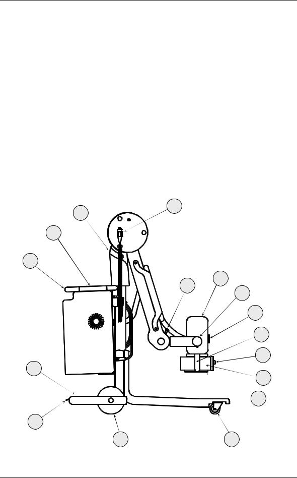
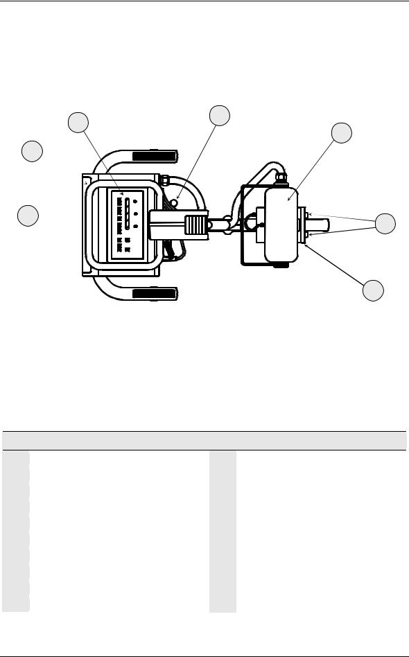
2.1MOBILE RADIOGRAPHIC UNIT
18
3
2
1
4
15
5
6
7
9
14
8
10
19
13 |
11 |
Section 1
Page 2 of 14 |
Doc. 7748 |
User’s Manual
GENERAL DESCRIPTION
12
2
4
1
16
9
8
MOBILE RADIOGRAPHIC UNIT
1 |
Transport handle with brake |
2 |
Control panel |
3 |
Handle for tilting (optional) |
4 |
X-ray tube head |
5 |
Lateral goniometer |
6 |
Front goniometer |
7 |
X-ray tube head positioning handle |
8 |
Collimator |
9 |
Adjustment of collimator diaphragms |
10 |
Rail for filters and accessories |
11Pivoting wheel (front wheel)
12Power supply cable holder
13Wheels (main wheel)
14Support for Tilting
15Pantograph arm lock
16Cassette holder
…
18X-ray control pushbutton
19Pedal for Stationary brake
Section 1
Doc. 7748 |
Page 3 of 14 |
User’s Manual
GENERAL DESCRIPTION
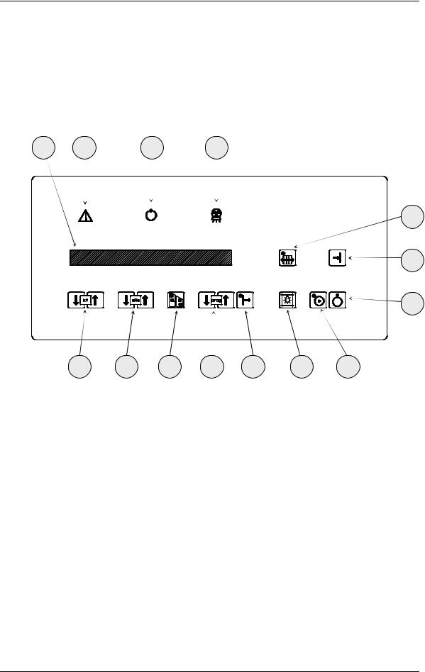
2.2 CONTROL PANEL
14 |
13 |
12 |
11 |
10
9
8
1 |
2 |
3 |
4 |
5 |
6 |
7 |
Section 1
Page 4 of 14 |
Doc. 7748 |
User’s Manual
1kV
2mAs
3
4Prog
5
GENERAL DESCRIPTION
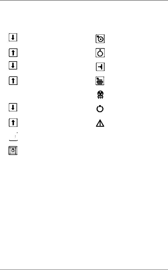
kV decrease |
7 |
Unit ON |
|
|
|
kV increase |
8 |
Unit OFF |
|
||
mAs decrease |
9 |
Data storage in anatomical |
|
technique |
|
mAs increase |
10 |
Potter-Bucky selection |
|
||
HP/LP (1) Power selection |
11 |
X-Ray exposure |
|
12 |
X-Ray ready |
N° of exams memorized in Technique |
|
|
Anatomical |
13 |
Alarm signalling |
|
||
Anatomical Technique Selection |
14 |
Display for Dates and Messages |
6 |
Collimator light activation |
(1)A change of the Power level involves a change of the used focal spot:
•High Power (HP) – Big Focus
•Low Power (LP) – Small Focus
In the following paragraphs the abbreviations HP and LP will be used.
Section 1
Doc. 7748 |
Page 5 of 14 |
User’s Manual
GENERAL DESCRIPTION
2.3 COLLIMATOR
50
51 |
54 |
52 |
52 |
53
COLLIMATOR
50 |
Collimator light on |
51 |
Adjustment of transverse diaphragm |
52 |
Rail for filters and accessories |
53 |
Retractile meter |
54 |
Adjustment of longitudinal diaphragm |
Section 1
Page 6 of 14 |
Doc. 7748 |

User’s Manual
GENERAL DESCRIPTION
3 TECHNICAL DATA
3.1 CLASSIFICATION OF THE APPARATUS
CLASSIFICATION – EN 60601 1 § 5
¯Type of protection against short circuit: CLASS I
¯Degree of protection against direct and indirect contact: TYPE B
¯Use conditions: CONTINUOUS WORKING WITH INTERMITTENT LOAD
¯Unit not to be used in the presence of an inflammable anaesthetic mixture with air or nitrous oxide
CLASSIFICATION – 93/42/EEC DIRECTIVE
¯In according with Annex IX: CLASS II b
3.2TECHNICAL CHARACTERISTICS
Electrical characteristics
SINGLE PHASE VOLTAGE |
|
|
|
|
230 Vac ± 10%, 16 A (Optional: 115 Vac ± 10%) |
|
||||
FREQUENCY |
|
|
|
|
50/60 Hz |
|
|
|||
MAX ABSORBED CURRENT |
|
STAND-BY WORKING |
|
1 A (115 Vac: 2.5 A) |
|
|
||||
|
|
|
|
|
|
|
|
|
||
|
RADIOGRAPHY WORKING |
|
12 A (115 Vac: 23 A) |
|
|
|||||
|
|
|
|
|
|
|||||
|
|
|
|
|
|
|
|
|
||
LINE COMPENSATION |
|
|
|
|
Automatic |
|
|
|||
LINE RESISTANCE |
|
|
|
|
< 2.5 Ω |
|
|
|
||
Radiological characteristics |
|
|
|
|
|
|
|
|||
|
|
|
|
|
|
|
|
|
|
|
|
|
|
15 kW |
|
|
30 kW |
|
|||
|
|
LP (Low Power) |
HP (High Power) |
|
LP (Low Power) |
HP (High Power) |
|
|||
MAX POWER |
7.5 kW |
15 kW |
|
|
7.5 kW |
30 kW |
|
|||
MAX CURRENT IN RADIOGRAPHY |
150 mA |
375 mA |
|
|
150 mA |
425 mA |
|
|||
EXPOSURE TIME |
3 ms ÷ 1.3 s |
1 ms ÷ 0.6 s |
|
|
3 ms ÷ 1.3 s |
1 ms ÷ 0.5 s |
|
|||
Selected by the processor according to the mAs |
|
|
||||||||
|
|
|
|
|||||||
WORKING FREQUENCY |
100 kHz |
|
|
|
|
|
|
|
||
RANGE KV |
40 ÷ 125 (Step of 1 kV) |
|
|
|
|
|
||||
RANGE MAS |
0.5 ÷ 200 in 25 values |
|
|
|
|
|
||||
A.T. PILOTAGE |
Inverter driven by IGBT |
|
|
|
|
|
||||
RIPPLE |
≤ 3% at Max Power |
|
|
|
|
|
|
|
||
TOTAL FILTRATION |
> 2.7 mmAl |
|
|
|
|
|
|
|
||
RISING TIME |
≤ 1 ms |
|
|
|
|
|
|
|
||
|
|
|
|
|
|
|
|
|
Section 1 |
|
|
|
|
|
|
|
|
|
|
|
|
|
Doc. 7748 |
|
|
|
|
|
|
|
Page 7 of 14 |
|
User’s Manual
GENERAL DESCRIPTION
X-Ray Tube Head
TYPE OF ANODE |
Rotation with speed 3000 RPM |
0.6 mm
FOCAL SPOTS
1.3 mm
All the other information relevant to the X-Ray Tube Head and to the X-Ray Tube can be found in the X-Ray Tube Head Technical Data Sheet
Collimator (optional)
|
SHUTTERS TO MULTIPLE PLANS |
Parallels and perpendicular with manual movement |
|||
|
All the other information relevant to the |
Collimator can be found in the relative Technical Data Sheet |
|||
|
Dosimeter |
(optional) |
|
|
|
|
|
|
|
|
|
|
MODEL |
|
|
Kermax-plus |
VacuDap 2000 with printer optional |
|
ACTIVE AREA |
|
|
146 x 146 mm2 |
147 x 147 mm2 |
|
MINIMAL DOSE RESOLUTION |
1 mGycm2 |
1 mGycm2 |
||
|
MAXIMAL MEASURABLE DOSE |
9999.9999 mGycm2 |
9999.9999 mGycm2 |
||
|
Operating modes and functionality |
|
|||
|
|
|
|
|
|
|
INTERFACE USER |
|
|
Polycarbonate flat keyboard with alphanumeric LCD display for all the operative |
|
|
|
|
|
parameters and messages of possible anomalous conditions – administrated by a |
|
|
|
|
|
microprocessor. |
|
|
OPERATING MODES |
|
RADIOGRAPHY |
Two-points techniques (kV-mAs) |
|
|
40 programmable anatomic technique (20 for LP and 20 for HP) |
||||
|
|
|
|
||
|
X-RAY CONTROL |
|
|
Distance control with double – click and extensible cable (≥4m) |
|
|
|
|
|
Filament current |
|
|
|
|
|
mAmin and mAmax |
|
|
|
|
|
Maximum exposure time |
|
|
SAFETY |
|
|
Temperature maximum X-ray tube head |
|
|
|
|
Count thermal units X-ray tube head |
||
|
|
|
|
||
Max kV, min kV, max ∆kV, max I
Anode rotation
Microprocessor self – test
Transport and storage conditions
MAXIMAL TEMPERATURE |
–10°C ÷ 55°C |
RECOMMENDED TEMPERATURE |
0°C ÷ 40°C |
RELATIVE HUMIDITY |
20% ÷ 90% |
ATMOSPHERIC PRESSURE |
500 hPa ÷ 1060 hPa |
Operating conditions |
|
|
|
TEMPERATURE |
10°C ÷ 40°C |
RELATIVE HUMIDITY |
30% ÷ 75% |
ATMOSPHERIC PRESSURE |
700 hPa ÷ 1060 hPa |
|
|
Section 1
Page 8 of 14 |
Doc. 7748 |

User’s Manual
GENERAL DESCRIPTION
Mechanical Characteristics
WIDTH |
734 mm |
LENGHT |
1259 mm |
HEIGHT |
1467 mm |
MIN SOURCE-FLOOR DISTANCE |
489 mm |
MAX SOURCE-FLOOR DISTANCE |
1997 mm |
MAX RANGE |
1091 mm |
FOCUS MAXIMUM HEIGHT, WITH RANGE 1000 MM |
1656 mm |
PIVOTING FRONT WHEEL Ø 75 |
360° |
MAXIMUM DIFFERENCE IN LEVEL WHICH CAN BE OVERCOME WITH TILTING |
25 mm |
BACK WHEELS DIAMETER |
Ø 200 |
MINIMUM DEFLECTING RAY |
977 mm |
WEIGHT |
191 kg (115 Vac: 205 kg) |
MOVEMENT |
Manual |
CASSETTE HOLDER 35X43 |
4 |
3.2.1 DIMENSIONS AND WEIGTHS
Drawing N°: 7742
Section 1
Doc. 7748 |
Page 9 of 14 |
User’s Manual
GENERAL DESCRIPTION
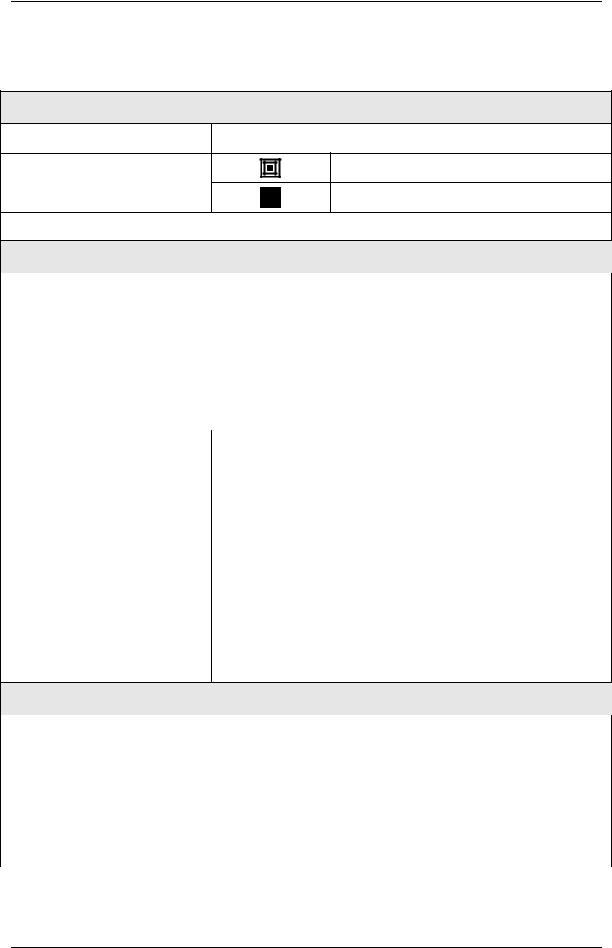
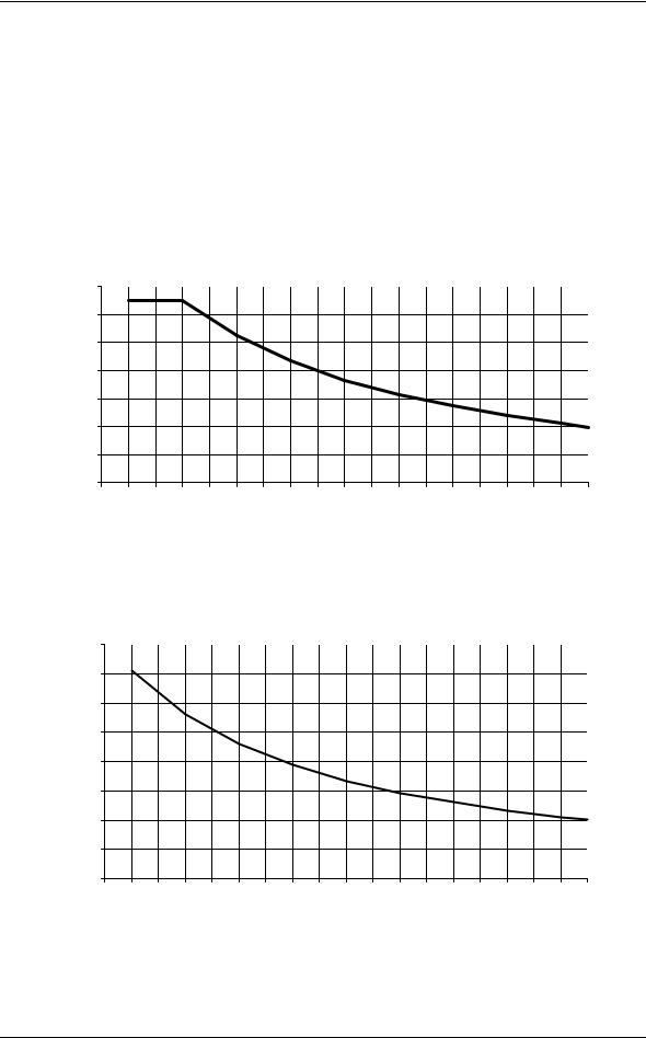
3.2.2KV – mA RELATIONSHIP
kV - mA Relationship in Radiography mode - 7.5kW
|
160,00 |
|
|
|
|
|
|
|
|
|
|
|
|
|
|
|
|
|
|
|
140,00 |
|
|
|
|
|
|
|
|
|
|
|
|
|
|
|
|
|
|
Radiography |
120,00 |
|
|
|
|
|
|
|
|
|
|
|
|
|
|
|
|
|
|
100,00 |
|
|
|
|
|
|
|
|
|
|
|
|
|
|
|
|
|
|
|
80,00 |
|
|
|
|
|
|
|
|
|
|
|
|
|
|
|
|
|
|
|
|
|
|
|
|
|
|
|
|
|
|
|
|
|
|
|
|
|
|
|
mA |
60,00 |
|
|
|
|
|
|
|
|
|
|
|
|
|
|
|
|
|
|
|
|
|
|
|
|
|
|
|
|
|
|
|
|
|
|
|
|
|
|
|
40,00 |
|
|
|
|
|
|
|
|
|
|
|
|
|
|
|
|
|
|
|
20,00 |
|
|
|
|
|
|
|
|
|
|
|
|
|
|
|
|
|
|
|
35 |
40 |
45 |
50 |
55 |
60 |
65 |
70 |
75 |
80 |
85 |
90 |
95 |
100 |
105 |
110 |
115 |
120 |
125 |
|
|
|
|
|
|
|
|
|
|
kV |
|
|
|
|
|
|
|
|
|
kV - mA Relationship in Radiography mode - 15kW
|
420,00 |
|
|
|
|
|
|
|
|
|
|
|
|
|
|
|
|
|
|
|
370,00 |
|
|
|
|
|
|
|
|
|
|
|
|
|
|
|
|
|
|
Radiography |
320,00 |
|
|
|
|
|
|
|
|
|
|
|
|
|
|
|
|
|
|
270,00 |
|
|
|
|
|
|
|
|
|
|
|
|
|
|
|
|
|
|
|
220,00 |
|
|
|
|
|
|
|
|
|
|
|
|
|
|
|
|
|
|
|
170,00 |
|
|
|
|
|
|
|
|
|
|
|
|
|
|
|
|
|
|
|
mA |
|
|
|
|
|
|
|
|
|
|
|
|
|
|
|
|
|
|
|
120,00 |
|
|
|
|
|
|
|
|
|
|
|
|
|
|
|
|
|
|
|
|
|
|
|
|
|
|
|
|
|
|
|
|
|
|
|
|
|
|
|
|
70,00 |
|
|
|
|
|
|
|
|
|
|
|
|
|
|
|
|
|
|
|
20,00 |
|
|
|
|
|
|
|
|
|
|
|
|
|
|
|
|
|
|
|
35 |
40 |
45 |
50 |
55 |
60 |
65 |
70 |
75 |
80 |
85 |
90 |
95 |
100 |
105 |
110 |
115 |
120 |
125 |
|
|
|
|
|
|
|
|
|
|
kV |
|
|
|
|
|
|
|
|
|
Section 1
Page 10 of 14 |
Doc. 7748 |
 Loading...