


SINUMERIK
SINUMERIK 828D
Hardware and Software
Service Manual
Valid for:
SINUMERIK 828D:
PPU 24x.2 BASIC T
PPU 24x.2 BASIC M
PPU 26x.2
PPU 28x.2
Software:
CNC software V4.3
03/2011
___________________
Preface
Safety notes |
1 |
|
|
System description |
2 |
|
|
Service cases - software |
3 |
|
|
Service cases - hardware |
4 |
|
|
Spare parts and accessories |
5 |
|
|
ESD guidelines |
A |
|
|
Appendix |
B |
|
|
6FC5397-5DP40-0BA0

Legal information
Warning notice system
This manual contains notices you have to observe in order to ensure your personal safety, as well as to prevent damage to property. The notices referring to your personal safety are highlighted in the manual by a safety alert symbol, notices referring only to property damage have no safety alert symbol. These notices shown below are graded according to the degree of danger.
 DANGER
indicates that death or severe personal injury will result if proper precautions are not taken.
 WARNING
indicates that death or severe personal injury may result if proper precautions are not taken.
 CAUTION
with a safety alert symbol, indicates that minor personal injury can result if proper precautions are not taken.
CAUTION
without a safety alert symbol, indicates that property damage can result if proper precautions are not taken.
NOTICE
indicates that an unintended result or situation can occur if the corresponding information is not taken into account.
If more than one degree of danger is present, the warning notice representing the highest degree of danger will be used. A notice warning of injury to persons with a safety alert symbol may also include a warning relating to property damage.
Qualified Personnel
The product/system described in this documentation may be operated only by personnel qualified for the specific task in accordance with the relevant documentation for the specific task, in particular its warning notices and safety instructions. Qualified personnel are those who, based on their training and experience, are capable of identifying risks and avoiding potential hazards when working with these products/systems.
Proper use of Siemens products
Note the following:
 WARNING
Siemens products may only be used for the applications described in the catalog and in the relevant technical documentation. If products and components from other manufacturers are used, these must be recommended or approved by Siemens. Proper transport, storage, installation, assembly, commissioning, operation and maintenance are required to ensure that the products operate safely and without any problems. The permissible ambient conditions must be adhered to. The information in the relevant documentation must be observed.
Trademarks
All names identified by ® are registered trademarks of the Siemens AG. The remaining trademarks in this publication may be trademarks whose use by third parties for their own purposes could violate the rights of the owner.
Disclaimer of Liability
We have reviewed the contents of this publication to ensure consistency with the hardware and software described. Since variance cannot be precluded entirely, we cannot guarantee full consistency. However, the information in this publication is reviewed regularly and any necessary corrections are included in subsequent editions.
Siemens AG |
Order number: 6FC5397-5DP40-0BA0 |
Copyright © Siemens AG 2011. |
Industry Sector |
03/2011 |
Technical data subject to change |
Postfach 48 48 |
|
|
90026 NÜRNBERG |
|
|
GERMANY |
|
|
Preface
SINUMERIK documentation
The SINUMERIK documentation is organized in the following categories:
●General documentation
●User documentation
●Manufacturer/service documentation
Additional information
You can find information on the following topics under the link (http://www.siemens.com/motioncontrol/docu):
●Ordering documentation/overview of documentation
●Additional links to download documents
●Using documentation online (finding and searching in manuals/information)
Please send any questions about the technical documentation (e.g. suggestions for improvement, corrections) to the following address: (mailto:docu.motioncontrol@siemens.com)
My Documentation Manager (MDM)
Under the following link you will find information to individually compile OEM-specific machine documentation based on the Siemens content: MDM (http://www.siemens.com/mdm)
Training
For information about the range of training courses, refer to:
●SITRAIN (www.siemens.com/sitrain) - training courses from Siemens for automation products, systems and solutions
●SinuTrain (www.siemens.com/sinutrain) - training software for SINUMERIK
FAQs
You can find Frequently Asked Questions in the Service&Support pages under Product
Support (www.siemens.com/automation/service&support).
SINUMERIK
You can find information on SINUMERIK under the following link: (http://www.siemens.com/sinumerik)
Hardware and Software |
|
Service Manual, 03/2011, 6FC5397-5DP40-0BA0 |
3 |

Preface
Target group
This document addresses maintenance and service personnel.
Benefits
Based on the Service Manual, the target group can correctly and safely perform service and maintenance work.
Utilization phase: Maintenance and service phase
Standard version
This documentation only describes the functionality of the standard version. Extensions or changes made by the machine manufacturer are documented by the machine manufacturer.
Other functions not described in this documentation might be executable in the control. This does not, however, represent an obligation to supply such functions with a new control or when servicing.
Further, for the sake of simplicity, this documentation does not contain all detailed information about all types of the product and cannot cover every conceivable case of installation, operation or maintenance.
Technical support
Country-specific telephone numbers for technical support are provided in the Internet under "Contact" (www.siemens.com/automation/service&support).
EC Declaration of Conformity
The EC declaration of conformity for the EMC directive can be found in the Internet (www.siemens.com/automation/service&support).
Here, enter the number 15257461 as the search term or contact your local Siemens office.
CompactFlash Cards
●The SINUMERIK CNC supports the file systems FAT16 and FAT32 for CompactFlash cards. You may need to format the memory card if you want to use a memory card from another device or if you want to ensure the compatibility of the memory card with the SINUMERIK. However, formatting the memory card will permanently delete all data on it.
●Do not remove the memory card while it is being accessed. This can lead to damage of the memory card and the SINUMERIK as well as the data on the memory card.
|
Hardware and Software |
4 |
Service Manual, 03/2011, 6FC5397-5DP40-0BA0 |

Preface
●If you cannot use a memory card with the SINUMERIK, it is probably because the memory card is not formatted for the control system (e.g. Ext3 Linux file system), the memory card file system is faulty or it is the wrong type of memory card.
●Insert the memory card carefully with the correct orientation into the memory card slot (take note of arrows, etc.). This way you avoid mechanical damage to the memory card or the device.
●Only use memory cards that have been approved by Siemens for use with SINUMERIK. Even though the SINUMERIK keeps to the general industry standards for memory cards, it is possible that memory cards from some manufacturers will not function perfectly in this device or are not completely compatible with it (you can obtain information on compatibility from the memory card manufacturer or supplier).
●For SINUMERIK 828D, only the memory card (1 GB) with order number 6FC5313- 5AG00-0AA1 is permitted.
Hardware and Software |
|
Service Manual, 03/2011, 6FC5397-5DP40-0BA0 |
5 |

Preface
|
Hardware and Software |
6 |
Service Manual, 03/2011, 6FC5397-5DP40-0BA0 |
Table of contents
|
Preface |
...................................................................................................................................................... |
3 |
1 |
Safety notes............................................................................................................................................. |
11 |
|
2 |
System ..................................................................................................................................description |
13 |
|
|
2.1 .......................................................................................................................... |
System overview |
13 |
|
2.2 ...................................................................................... |
System versions horizontal and vertical |
15 |
|
2.3 .................................................................................... |
System versions, BASIC T and BASIC M |
17 |
3 |
Service ..........................................................................................................................cases - software |
21 |
|
|
3.1 ................................................................................................................... |
Backing up user data |
22 |
|
3.1.1 ................................................................................................ |
This is how you backup user data |
22 |
|
3.1.2 .................................................................................. |
This is how you load the user data backup |
25 |
|
3.2 ........................................................................................... |
Generating a commissioning archive |
27 |
|
3.2.1 .............. |
This is how you generate a series commissioning archive on an external data carrier |
27 |
|
3.2.2 ............... |
This is how you import a series commissioning archive from an external data carrier |
30 |
3.2.3This is how you generate a series commissioning archive on the system CompactFlash
Card ............................................................................................................................................. |
32 |
3.2.4This is how you import a series commissioning archive from the system CompactFlash
|
|
Card ............................................................................................................................................. |
34 |
|
3.3 |
Software backup.......................................................................................................................... |
36 |
|
3.3.1 |
This is how you generate a software backup............................................................................... |
36 |
|
3.3.2 |
This is how you install a software backup.................................................................................... |
40 |
|
3.4 |
Software update........................................................................................................................... |
44 |
|
3.4.1 |
This is how you update the software ........................................................................................... |
44 |
|
3.5 |
Mini boot system on the CompactFlash Card.............................................................................. |
48 |
|
3.5.1 |
This is how you generate a mini boot system.............................................................................. |
48 |
|
3.5.2 |
This is how you install a software backup using the mini boot system........................................ |
52 |
|
3.6 |
Licensing...................................................................................................................................... |
55 |
|
3.6.1 |
Licensing after replacing the system CompactFlash Card.......................................................... |
55 |
|
3.6.2 |
This is how you license a CNC option......................................................................................... |
55 |
|
3.6.3 |
This is how you determine missing licenses/options................................................................... |
57 |
|
3.6.4 |
This is how you generated a new license key ............................................................................. |
58 |
|
3.6.5 |
This is how you display the actual license key ............................................................................ |
61 |
|
3.7 |
Enter the final end user data (EUNA).......................................................................................... |
64 |
|
3.7.1 |
This is how you generate the machine logbook........................................................................... |
64 |
|
3.7.2 |
This is how you make a new entry in the logbook....................................................................... |
66 |
|
3.7.3 |
This is how you save the machine identity .................................................................................. |
68 |
|
3.7.4 |
This is how you send the end user final destination data............................................................ |
69 |
4 |
Service cases - hardware........................................................................................................................ |
73 |
|
|
4.1 |
PPU 24x.2/26x.2/28x.2................................................................................................................ |
74 |
|
4.1.1 |
PPU status displays..................................................................................................................... |
74 |
Hardware and Software |
|
||
Service Manual, 03/2011, 6FC5397-5DP40-0BA0 |
7 |
||

Table of contents
4.1.2 |
This is how you remove the PPU................................................................................................ |
77 |
4.1.3 |
This is how you install the PPU................................................................................................... |
78 |
4.2 |
Replacing the system CompactFlash Card................................................................................. |
79 |
4.2.1 |
This is how you remove the system CompactFlash Card........................................................... |
79 |
4.2.2 |
This is how you insert the system CompactFlash Card.............................................................. |
81 |
4.3 |
SINAUT modem.......................................................................................................................... |
84 |
4.3.1 |
LED status displays..................................................................................................................... |
84 |
4.3.2 |
This is how you insert the SIM card............................................................................................ |
85 |
4.3.3 |
This is how you load the factory settings.................................................................................... |
91 |
4.4 |
Machine control panels............................................................................................................... |
92 |
4.4.1 |
Status displays MCP 310C PN................................................................................................... |
92 |
4.4.2 |
This is how you remove the MCP 310C PN................................................................................ |
93 |
4.4.3 |
This is how you install the MCP 310C PN .................................................................................. |
95 |
4.4.4 |
Status displays, MCP 483C PN.................................................................................................. |
96 |
4.4.5 |
This is how you remove the MCP 483C PN................................................................................ |
97 |
4.4.6 |
This is how you install the MCP 483C PN .................................................................................. |
99 |
4.5 |
I/O modules............................................................................................................................... |
101 |
4.5.1 |
Status displays PP 72/48D PN ................................................................................................. |
101 |
4.5.2 |
This is how you remove the PP 72/48D PN.............................................................................. |
102 |
4.5.3 |
This is how you install the PP 72/48D PN................................................................................. |
104 |
4.5.4 |
Status displays PP 72/48D 2/2A PN......................................................................................... |
105 |
4.5.5 |
This is how you remove the PP 72/48D 2/2A PN..................................................................... |
107 |
4.5.6 |
This is how you install the PP 72/48D 2/2A PN........................................................................ |
109 |
4.6 |
Expansion module NX10.3........................................................................................................ |
110 |
4.6.1 |
NX10.3 status displays.............................................................................................................. |
110 |
4.6.2 |
NX10.3 connections.................................................................................................................. |
111 |
4.6.3 |
This is how you remove the NX10.3......................................................................................... |
112 |
4.6.4 |
This is how you install the NX10.3............................................................................................ |
113 |
4.7 |
Installing SINAMICS components............................................................................................. |
115 |
4.7.1 |
Releasing with a screwdriver.................................................................................................... |
115 |
4.7.2 |
Protective conductor connection and shield support................................................................ |
116 |
4.8 |
SINAMICS S120 Combi............................................................................................................ |
117 |
4.8.1 |
S120 Combi status displays...................................................................................................... |
117 |
4.8.2 |
Connections, 3-axis module...................................................................................................... |
119 |
4.8.3 |
Connections, 4-axis module...................................................................................................... |
121 |
4.8.4 |
How to mount an S120 Combi Power Module.......................................................................... |
123 |
4.8.5 |
This is how you remove the front panel.................................................................................... |
124 |
4.8.6 |
This is how you open the DC link cover.................................................................................... |
126 |
4.8.7 |
This is how you connect the DC link busbars and 24 V busbars.............................................. |
128 |
4.8.8 |
To connect the second component........................................................................................... |
130 |
4.8.9 |
This is how you remove the internal fan ................................................................................... |
133 |
4.8.10 |
This is how you install the internal fan...................................................................................... |
136 |
4.8.11 |
This is how you install the external fan..................................................................................... |
136 |
4.8.12 |
This is how you clean the heat sink of the S120 Combi........................................................... |
141 |
4.9 |
Motor Module Booksize Compact format.................................................................................. |
144 |
4.9.1 |
Motor Module Booksize Compact status displays.................................................................... |
144 |
4.9.2 |
Motor Module connections........................................................................................................ |
145 |
4.9.3 |
This is how you mount a Motor Module Booksize Compact..................................................... |
147 |
|
|
Hardware and Software |
8 |
Service Manual, 03/2011, 6FC5397-5DP40-0BA0 |
|

|
|
Table of contents |
4.9.4 |
This is how you replace the fan on a Motor Module Booksize Compact |
...................................148 |
4.10 |
Single Motor Modules................................................................................................................ |
151 |
4.10.1 |
SMM status displays.................................................................................................................. |
151 |
4.10.2 |
SMM connections ...................................................................................................................... |
152 |
4.10.3 |
This is how you remove a Motor Module................................................................................... |
153 |
4.10.4 |
This is how you install a Motor Module...................................................................................... |
155 |
4.11 |
Double Motor Modules............................................................................................................... |
158 |
4.11.1 |
DMM status displays.................................................................................................................. |
158 |
4.11.2 |
DMM connections...................................................................................................................... |
159 |
4.11.3 |
This is how you remove a Motor Module................................................................................... |
160 |
4.11.4 |
This is how you install a Motor Module...................................................................................... |
162 |
4.12 |
Smart Line Modules................................................................................................................... |
165 |
4.12.1 |
SLM (< 16 kW) status displays.................................................................................................. |
165 |
4.12.2 |
SLM (< 16 kW) connections....................................................................................................... |
166 |
4.12.3 |
SLM (16 kW and higher) status displays................................................................................... |
167 |
4.12.4 |
SLM (16 kW and higher) connections........................................................................................ |
168 |
4.12.5 |
This is how you remove an SLM................................................................................................ |
169 |
4.12.6 |
This is how you install an SLM................................................................................................... |
171 |
4.13 |
Active Line Modules................................................................................................................... |
173 |
4.13.1 |
ALM status displays................................................................................................................... |
173 |
4.13.2 |
ALM connections ....................................................................................................................... |
174 |
4.13.3 |
This is how you remove an ALM................................................................................................ |
175 |
4.13.4 |
This is how you install an ALM................................................................................................... |
177 |
4.14 |
Sensor Modules Cabinet............................................................................................................ |
179 |
4.14.1 |
SMC10/SMC20 status displays ................................................................................................. |
179 |
4.14.2 |
SMC10/SMC20 connections...................................................................................................... |
180 |
4.14.3 |
This is how you remove an SMC10/SMC20.............................................................................. |
181 |
4.14.4 |
This is how you install an SMC10/SMC20................................................................................. |
182 |
4.14.5 |
SMC30 status displays .............................................................................................................. |
183 |
4.14.6 |
SMC30 connections................................................................................................................... |
184 |
4.14.7 |
This is how you remove an SMC30........................................................................................... |
185 |
4.14.8 |
This is how you install an SMC30.............................................................................................. |
187 |
4.15 |
Sensor Modules External........................................................................................................... |
189 |
4.15.1 |
SME20 connections................................................................................................................... |
189 |
4.15.2 |
This is how you remove an SME20 and install it again............................................................. |
189 |
4.15.3 |
SME25 connections................................................................................................................... |
190 |
4.15.4 |
This is how you remove an SME25 and install it again............................................................. |
191 |
4.15.5 |
SME120 connections................................................................................................................. |
192 |
4.15.6 |
This is how you remove an SME120 and install it again........................................................... |
193 |
4.15.7 |
SME125 connections................................................................................................................. |
194 |
4.15.8 |
This is how you remove an SME125 and install it again........................................................... |
194 |
4.16 |
Terminal Modules ...................................................................................................................... |
196 |
4.16.1 |
TM54F status displays............................................................................................................... |
196 |
4.16.2 |
TM54F connections ................................................................................................................... |
198 |
4.16.3 |
This is how you remove an TM54F............................................................................................ |
198 |
4.16.4 |
This is how you install a TM54F................................................................................................. |
200 |
4.17 |
Hub Modules.............................................................................................................................. |
201 |
4.17.1 |
DMC20 status displays.............................................................................................................. |
201 |
Hardware and Software |
|
|
Service Manual, 03/2011, 6FC5397-5DP40-0BA0 |
9 |
|

Table of contents
|
4.17.2 |
DMC20 connections .................................................................................................................. |
202 |
|
4.17.3 |
This is how you remove a DMC20 ............................................................................................ |
202 |
|
4.17.4 |
This is how you install a DMC20 ............................................................................................... |
204 |
|
4.17.5 |
DME20 connections .................................................................................................................. |
205 |
|
4.17.6 |
This is how you mount a DME20 .............................................................................................. |
206 |
|
4.17.7 |
Connection to X524 electronics power supply .......................................................................... |
207 |
5 |
Spare parts and accessories ................................................................................................................. |
209 |
|
|
5.1 |
Spare parts for the S120 Combi ............................................................................................... |
210 |
A |
ESD guidelines...................................................................................................................................... |
211 |
|
|
A.1 |
RI suppression measures ......................................................................................................... |
211 |
|
A.2 |
ESD measures .......................................................................................................................... |
212 |
B |
Appendix |
................................................................................................................................................ |
213 |
|
B.1 |
List of abbreviations .................................................................................................................. |
213 |
|
B.2 ........................................................................................................... |
Documentation overview |
216 |
|
Index...................................................................................................................................................... |
|
217 |
|
Hardware and Software |
10 |
Service Manual, 03/2011, 6FC5397-5DP40-0BA0 |
Safety notes |
1 |
The following notices are intended firstly for your personal safety and secondly to prevent damage occurring to the product described or any connected devices and machines. Nonobservance of the warnings can result in severe personal injury or property damage.
 DANGER
Only appropriately qualified personnel may commission/start-up SINUMERIK equipment.
The personnel must take into account the information provided in the technical customer documentation for the product, and be familiar with and observe the specified danger and warning notices.
When electrical equipment and motors are operated, the electrical circuits automatically conduct a dangerous voltage.
When the system is operating, dangerous axis movements may occur throughout the entire work area.
A potential fire hazard exists due to the energy being transferred in the equipment and the work materials used.
All work on the electrical system must be performed after the system has been switched off and disconnected from the power supply.
 DANGER
Proper transportation, expert storage, installation and mounting, as well as careful operation and maintenance are essential for this SINUMERIK device to operate correctly and reliably.
The details in the catalogs and proposals also apply to the design of special equipment versions.
In addition to the danger and warning information provided in the technical customer documentation, the applicable national, local, and system-specific regulations and requirements must be taken into account.
Only class DVC A protective extra-low voltages (PELVs) may be connected to connections and terminals up to 60 V DC in accordance with EN 61800-5-1.
Should it be necessary to test or take measurements on live equipment, then the specifications and procedural instructions defined in Accident Prevention Regulation BGV A2 must be adhered to, in particular § 8 "Permissible deviations when working on live components". Suitable electric tools should be used.
Hardware and Software |
|
Service Manual, 03/2011, 6FC5397-5DP40-0BA0 |
11 |

Safety notes
 DANGER
Repairs to devices that have been supplied by our company may only be carried out by SIEMENS customer service or by repair centers authorized by SIEMENS.
When replacing parts or components, only use those parts that are included in the spare parts list.
EMERGENCY STOP/EMERGENCY OFF devices according to EN 60204-1 (VDE 0113 Part 1) must remain active in all modes of the automation equipment. Resetting the EMERGENCY STOP/EMERGENCY OFF device must not cause an uncontrolled or undefined restart.
Anywhere in the automation equipment where faults might cause physical injury or major material damage, in other words, where faults could be dangerous, additional external precautions must be taken, or facilities must be provided, that guarantee or enforce a safe operational state, even when there is a fault (e.g. using an independent limit value switch, mechanical locking mechanisms, EMERGENCY STOP/EMERGENCY OFF devices).
 DANGER
External power supply units for supplying components of the drive control must have safety isolation from circuits with dangerous voltages (DVC A according to EN 61800-5-1; SELV/PELV). In addition only power units with control circuits that have safety isolation from circuits with dangerous voltages may be connected.
|
Hardware and Software |
12 |
Service Manual, 03/2011, 6FC5397-5DP40-0BA0 |
System description |
2 |
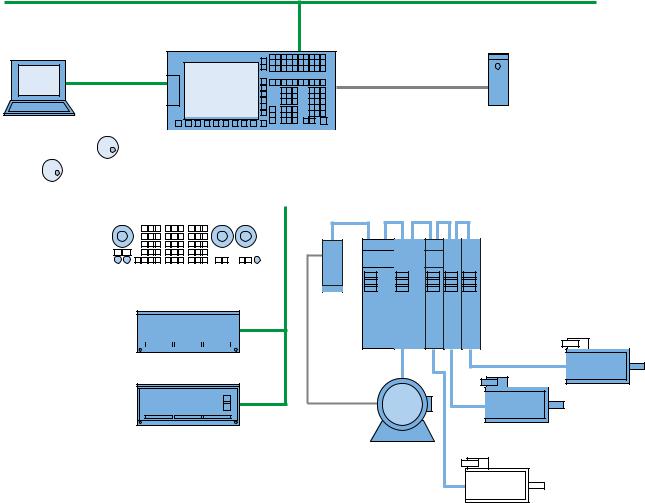
2.1System overview
System design
The following configuration shows a typical example with SINAMICS S120 booksize:
&RPSDQ\ QHWZRUN ,QGXVWULDO (WKHUQHW
6,180(5,. '
3HHU WR SHHU
QRQ FURVVHG
PRGHP FDEOH
6,1$87 0'
3* 3&
|
|
|
|
|
|
|
|
|
|
|
|
|
|
|
|
|
|
|
|
|
|
|
|
|
|
|
|
|
|
|
|
|
|
|
'5,9( &/L4 |
||||||||||
|
|
|
|
|
|
|
|
|
|
|
|
|||||||||||
|
|
|
|
|
|
|
|
|
|
|
|
|||||||||||
|
|
|
|
|
|
|
|
|
|
|
|
|
|
|
|
|
|
|
|
|
|
|
|
|
|
|
|
|
|
|
|
3/& , 2 LQWHUIDFH EDVHG |
|
|
|
|
|
|
|
||||||
[ KDQGZKHHO |
|
|
RQ 352),1(7 |
|
|
|
|
|
|
|
||||||||||||
|
|
|
|
|
|
|
|
|
|
|
|
|
|
|
6,1$0,&6 6 |
|
||||||
|
|
|
|
|
|
|
|
|
|
|
|
|
|
|
|
|
|
|
|
|
|
|
|
|
|
|
|
|
|
|
|
|
|
|
|
|
|
|
|
|
|
|
|
|
|
|
|
|
|
|
|
|
|
|
|
|
|
|
|
|
|
|
|
|
|
|
|
|
|
|
|
|
|
|
|
|
|
|
|
|
|
|
|
|
|
|
|
|
|
|
|
|
|
|
|
|
|
|
|
|
|
|
|
|
|
|
|
|
|
|
|
|
|
|
0&3 31
60&
|
|
|
|
|
|
6/0 |
600 |
600 |
600 |
600 |
|
|
|
|
|
|
|
|
|
|
|||||
|
|
|
|
|
|
|
||||||
|
|
|
|
|
|
|
||||||
|
|
|
|
|
|
|
|
|||||
|
|
|
|
|
|
|
|
|
|
|
|
|
|
|
|
|
|
|
|
|
|
|
|
|
|
33 ' 31
6\QFKURQRXV |
PRWRU |
|
|
|
6\QFKURQRXV |
|||
33 ' $ 31 |
|
|
|
|
|
|
|
|
|
PRWRU |
|||
|
,QGXFWLRQ PRWRU |
|
|
|
|
|
|
|
|
|
|
|
|
|
|
|
|
|
|
|
|
|
|
|
|
|
|
|
|
|
|
|
|
|
|
|
|
|
|
|
|
|
|
|
|
|
|
|
6\QFKURQRXV PRWRU
Figure 2-1 Configuration example 1: Basic configuration with 4 axes
Hardware and Software
Service Manual, 03/2011, 6FC5397-5DP40-0BA0 |
13 |
System description
2.1 System overview
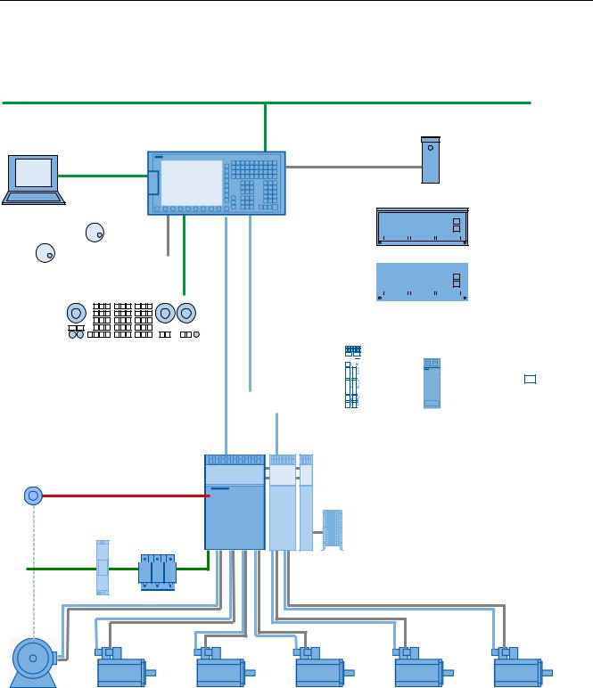
The following configuration shows the maximum expansion stage with SINAMICS S120 Combi:
&RPSDQ\ QHWZRUN ,QGXVWULDO (WKHUQHW
6,180(5,. '
QRQ FURVVHG
PRGHP FDEOH
3HHU WR SHHU
3* 3&
|
|
|
|
|
|
|
|
|
|
|
|
|
|
|
|
|
|
|
|
|
|
|
|
|
|
|
|
|
|
|
|
|
|
|
|
|
|
|
|
|
|
|
|
|
|
|
|
|
|
|
|
|
|
|
|
|
|
|
|
|
|
|
|
|
|
|
|
|
|
|
|
|
|
|
|
|
|
|
|
|
|
|
|
|
|
|
|
|
|
|
|
|
|
|
|
|
|
|
|
|
|
|
|
|
|
|
|
|
|
|
|
|
|
|
|
|
|
|
|
|
|
|
|
|
|
|
|
|
|
|
|
|
|
|
|
|
|
33 ' 31 |
|
|
|
|
|
|
|
||||||||||||||
|
|
|
|
|
|
|
|
|
|
|
|
|
|
|
|
|
|||||||||||||||
|
[ KDQGZKHHO |
|
|
|
|
|
|
|
|
|
|
|
|
|
|
|
|
|
|
|
|
|
|
|
|
|
|||||
|
|
|
|
|
|
|
|
|
|
|
|
|
|
|
|
|
|
|
|
|
|
|
|
|
|
||||||
|
|
|
|
|
|
|
|
|
|
|
|
|
|
|
|
|
|
|
|
|
|
|
|||||||||
|
|
|
|
|
|
|
|
3/& , 2 LQWHUIDFH EDVHG |
|
|
|
|
|
|
|||||||||||||||||
|
|
|
|
|
|
|
|
|
|
|
|
|
|
|
|
|
|
|
|
|
|
|
|
|
|
|
|
|
|
|
|
|
|
|
|
|
|
|
|
|
|
|
|
|
|
|
|||||||||||||||||
|
|
|
|
|
|
|
|
RQ 352),1(7 |
|
|
|
|
|||||||||||||||||||
|
|
|
|
|
|
|
33 ' $ 31 |
|
|
|
|
|
|||||||||||||||||||
|
|
|
|
|
|
|
70 ) |
|
|
|
|
|
|
|
|
|
|
|
|
|
|
|
|||||||||
|
|
|
|
|
|
|
|
|
|
|
|
|
|
'0& '0( |
|
|
|
|
|||||||||||||
|
|
|
|
|
|
|
|
|
|
|
|
|
|
|
|
|
|
|
|
|
|||||||||||
|
|
|
|
|
|
|
|
|
|
|
|
|
|
|
|
|
|
|
|
|
|||||||||||
|
|
|
|
|
|
|
|
|
|
|
|
|
|
|
|
|
|
|
|
|
|
|
|
|
|
|
|
|
8S WR |
||
|
0&3 31 |
|
|
|
|
|
|
|
|
|
|
|
|
|
|
|
|
|
|
|
|
|
|
|
|
|
|
|
|
||
|
|
|
|
|
|
|
|
|
|
|
|
|
|
|
|
|
|
|
|
|
|
|
|
|
|
|
|
|
/LQHDU VFDOHV |
||
|
|
|
|
|
|
|
|
|
|
|
|
|
|
|
|
|
|
|
|
|
|
|
|
|
|
|
|
|
|||
|
|
|
|
|
|
|
|
'5,9( &/L4 |
|
|
|
|
|
|
|
|
|
|
|
|
|
|
|
|
|
|
|
|
|||
|
|
|
|
|
|
|
|
|
|
|
|
|
|
|
|
|
|
|
|
|
|
|
|
|
|
|
|
||||
|
|
|
|
|
|
|
|
|
|
|
|
|
|
|
|
|
|
|
|
|
|
|
|
|
|
|
|
||||
|
|
|
|
|
|
|
|
|
|
|
|
|
|
|
|
|
|
|
|
|
|
|
|
|
|
|
|
|
|
|
|
|
|
|
|
|
|
|
|
|
|
|
|
|
|
|
|
|
|
|
|
|
|
|
|
|
|
|
|
|
|
|
|
|
|
|
|
|
|
|
|
|
|
|
|
|
|
|
|
|
|
|
|
|
|
|
|
|
|
|
|
|
|
|
|
|
|
|
|
|
|
|
|
|
|
|
|
|
|
|
|
|
|
|
|
|
|
|
|
|
|
|
|
|
|
|
|
|
6,1$0,&6 |
|
|
6 &RPEL |
'RXEOH 0RWRU 0RGXOH %RRNVL]H &RPSDFW |
|
|
|
|
3RZHU 0RGXOH |
&RQWURO 6XSSO\ 0RGXOH |
77/ VSLQGOH HQFRGHU |
|
|
|
|
|
|
|
%UDNLQJ 0RGXOH %UDNLQJ UHVLVWRU |
2SWLRQDO |
|
|
/LQH ILOWHU |
/LQH UHDFWRU |
|
$& |
|
|
9 |
|
|
|
|
0RWRU FDEOH |
|
|
'5,9( &/L4 |
6SLQGOH PRWRU |
6HUYRPRWRU |
6HUYRPRWRU |
6HUYRPRWRU |
6HUYRPRWRU |
6HUYRPRWRU |
|
6XSSOHPHQWDU\ |
|
|
|
|
|
VSLQGOH |
|
|
|
|
Figure 2-2 Configuration example 2: Maximum expansion stage with 6 axes and with Safety Integrated
|
Hardware and Software |
14 |
Service Manual, 03/2011, 6FC5397-5DP40-0BA0 |

System description
2.2 System versions horizontal and vertical
2.2System versions horizontal and vertical
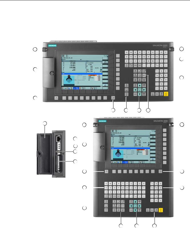
Front of the PPU versions 26x.2 and 28x.2
|
|
|
|
|
|
|
|
|
|
|
|
|
|
|
|
|
|
|
|
|
|
|
|
|
|
|
Protective cover for user interfaces Menu back key
Alphabetic key group Control key group Hotkey group Cursor key group
Hardware and Software |
|
Service Manual, 03/2011, 6FC5397-5DP40-0BA0 |
15 |
System description
2.2 System versions horizontal and vertical
Numerical block
Menu forward key
3/8" threads for additional components
Protective cover for user interfaces
X127 Ethernet (service socket)
Status LED: RDY, NC, CF
X125 USB interface
|
Slot for CompactFlash Card with user data |
Figure 2-3 System versions
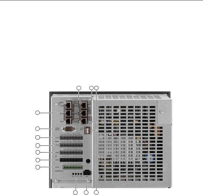
Rear of the PPU 26x.2 and 28x.2
|
|
|
|
|
|
|
|
③
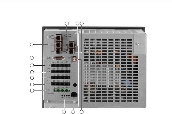
X122, X132 |
Digital inputs/outputs, drive |
X242, X252 |
Digital inputs/outputs, NC |
X143 |
Handwheels |
M, T2, T1, T0 |
Measuring sockets |
X1 |
Power supply |
X135 |
USB interface: For service purposes only |
X130 |
Ethernet LAN |
PN 1, PN 2 |
PLC I/O Interface |
SYNC, FAULT |
Status LEDs |
X100, X101, X102 |
DRIVE-CLIQ interfaces |
X140 |
Serial interface RS232 |
Figure 2-4 Interfaces on the rear side of the PPU
|
Hardware and Software |
16 |
Service Manual, 03/2011, 6FC5397-5DP40-0BA0 |
System description
2.3 System versions, BASIC T and BASIC M
2.3System versions, BASIC T and BASIC M
Front panel of the SINUMERIK 828D BASIC T with interfaces


|
|
|
|
|
|
|
|||

|
|
|
|
|
|
|
|||
|
|
|
|
|
|
||||

|
|
|
Protective cover for user interfaces Menu back key
Alphabetic key group Control key group
Hardware and Software |
|
Service Manual, 03/2011, 6FC5397-5DP40-0BA0 |
17 |

System description
2.3 System versions, BASIC T and BASIC M
Hotkey group
Cursor key group
Numerical block
Menu forward key
3/8" threads for additional components
X127 Ethernet (service socket)
Status LED: RDY, NC, CF
X125 USB interface
|
Slot for CompactFlash Card with user data |
Figure 2-5 |
System versions |
|
Hardware and Software |
18 |
Service Manual, 03/2011, 6FC5397-5DP40-0BA0 |
System description
2.3 System versions, BASIC T and BASIC M
Rear of the PPU 24x.2
|
|
|
|
|
|
|
|
③
X122, X132 |
Digital inputs/outputs, drive |
X242, X252 |
Digital inputs/outputs, NC |
X143 |
Handwheels |
M, T2, T1, T0 |
Measuring sockets |
X1 |
Power supply |
X135 |
USB interface: For service purposes only |
X130 |
Ethernet LAN |
PN |
PLC I/O Interface |
SYNC, FAULT |
Status LEDs |
X100, X101, X102 |
DRIVE-CLIQ interfaces |
X140 |
Serial interface RS232 |
Figure 2-6 Interfaces at the rear
Hardware and Software |
|
Service Manual, 03/2011, 6FC5397-5DP40-0BA0 |
19 |

System description
2.3 System versions, BASIC T and BASIC M
|
Hardware and Software |
20 |
Service Manual, 03/2011, 6FC5397-5DP40-0BA0 |
Service cases - software |
3 |
Overview
The following software tools should be used for the subsequently described service activities and to backup system and user data:
●Toolbox CD V2.6 SINUMERIK 828D with the following contents:
–PLC Programming Tool for Integrated PLC
–Commissioning software for SINAMICS S120
–Recovery system
●RCS Commander V2.6 SP1
Backing up log files
If system problems occur, then it is necessary to backup all of the existing log files in order to provide these to the hotline for diagnostics. There is a special shortcut key for this function:
CTRL + ALT + D
This function generates a directory on the User CF card or on the front USB. If both are available, then the directory is created in both storage media.
Example
The directory name has the following structure: LOG_Date_Time LOG_091102_083615 stands for a directory generated on 02.11.2009 at 8:36:15.
This therefore ensures that a directory is not overwritten by pressing CTRL + ALT + D several times. The directory contains all of the logbook and debug information available in the system.
Hardware and Software |
|
Service Manual, 03/2011, 6FC5397-5DP40-0BA0 |
21 |
Service cases - software
3.1 Backing up user data
3.1Backing up user data
3.1.1This is how you backup user data
Application
A backup of the data in the complete memory is generated with the "Save data" function.
This data backup must be performed for every control that has been commissioned in order to be able to quickly restore the control system in the case of data loss. If the "Create software backup" function is used, then it is essential to backup the memory data.
With the data backup, a copy of the limited buffered memory is stored in the permanent memory. Backup of selected data (e.g. only machine data and no workpiece programs) is not possible.
Data can be backed up without a password: i.e. always!
Note
Data backup
After making important changes to the data, immediately backup data, e.g. after the 1st commissioning and the 2nd commissioning.
Backing up data
Preconditions:
●The control system has powered up.
●The power supply voltage is guaranteed during the data backup. Proceed as follows to generate the internal data backup:
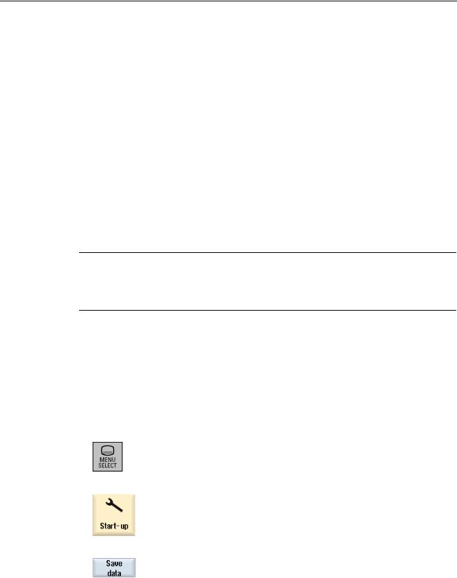
1. Press the <MENU SELECT> key.
2.Select the "Start-up" operating area.
3.Press the "Save data" softkey.
|
Hardware and Software |
22 |
Service Manual, 03/2011, 6FC5397-5DP40-0BA0 |
Service cases - software
3.1 Backing up user data
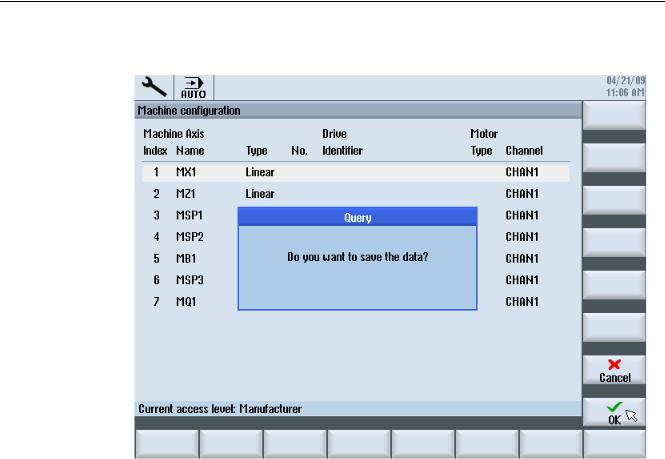
4. This is followed by the "Query" to backup data:
Hardware and Software |
|
Service Manual, 03/2011, 6FC5397-5DP40-0BA0 |
23 |
Service cases - software
3.1Backing up user data
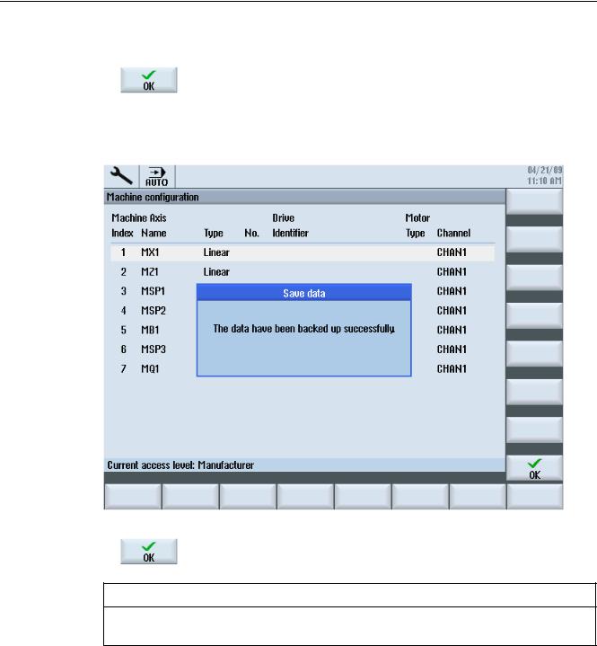
5.Press the "OK" softkey to backup the data.
–A progress indicator indicates the status of the data backup.
–After the data backup has been successfully completed, the following message is output:
6. Confirm this message with "OK".
NOTICE
While the data is being backed up, the control system must neither be operated, nor turned off.
|
Hardware and Software |
24 |
Service Manual, 03/2011, 6FC5397-5DP40-0BA0 |
Service cases - software
3.1 Backing up user data
3.1.2This is how you load the user data backup
NOTICE
If this function is activated, the actual system data is replaced by the data backup.
Procedure
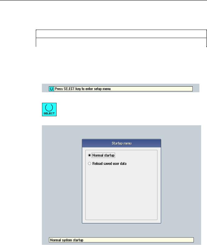
Proceed as follows to load the internal data backup:
1.The following display is shown when booting after power-on:
2.To start the Setup menu, press the <SELECT> key.
You now go to the Setup menu:
Hardware and Software |
|
Service Manual, 03/2011, 6FC5397-5DP40-0BA0 |
25 |
Service cases - software
3.1Backing up user data
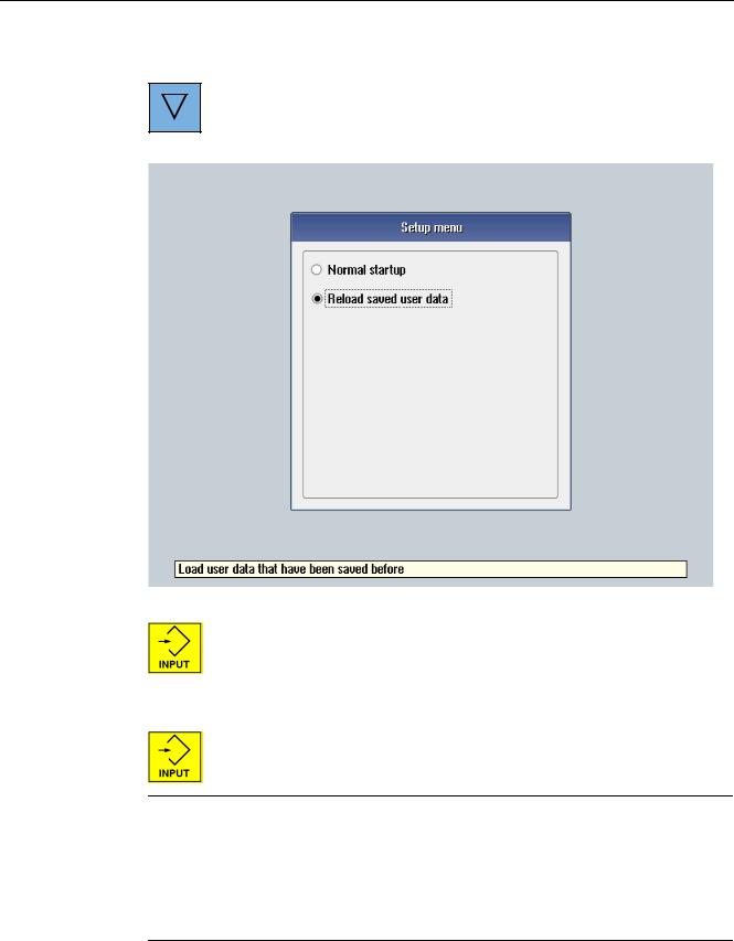
3.Using the arrow key, select the menu item "Reload saved user data".
4.Confirm that the backup is loaded by pressing the key <INPUT>.
5.Confirm the confirmation prompt by pressing the <INPUT> key. Are you sure you want to reload saved user data?"
Note Booting
If data is lost from the buffer memory, the data saved in the permanent memory will automatically be reloaded to the memory at POWER ON.
If the control boots with the backed-up data, the following message is displayed: "4062 Data backup copy has been loaded".
|
Hardware and Software |
26 |
Service Manual, 03/2011, 6FC5397-5DP40-0BA0 |

Service cases - software
3.2 Generating a commissioning archive
3.2Generating a commissioning archive
Overview
A commissioning archive is used to completely backup all of the data required for the machine function.
A commissioning archive can be generated on an external data carrier, e.g. USB-FlashDrive or CompactFlash card at the front panel of the control as well as on the system CompactFlash Card.
Note
Data must always be backed up before a machine is delivered. Only then can it be ensured that in the case of service, the delivery condition of the machine can be restored.
In addition, it may be necessary to generate a commissioning archive before service activities are started. This means that it can be guaranteed that the actual state of the machine can be restored after the activities have been completed.
3.2.1This is how you generate a series commissioning archive on an external data carrier
Generating an archive on an external data carrier
Procedure:
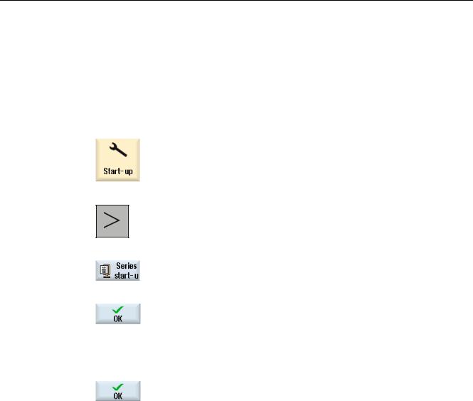
1.Select the "Start-up" operating area.
2.Press the menu forward key.
3.Press the "Series startup" softkey.
Hardware and Software |
|
Service Manual, 03/2011, 6FC5397-5DP40-0BA0 |
27 |
Service cases - software
3.2Generating a commissioning archive
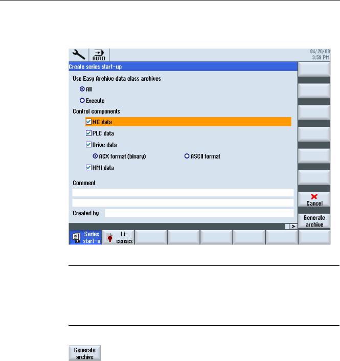
4.Activate "Series startup".
The "Create Series Startup" window opens.
5.Select the desired control components.
Note
Easy Archive
Select all of the components, unless it is known that individual components do not deviate from the Siemens standard.
Select all data classes, unless only certain data (e.g. INDIVIDUAL) are to be backed up.
6.Press the "Generate archive" softkey.
The "Generate Archive: Select Archive" window opens.
7.Select the storage location of the archive:
–USER USB: USB-FlashDrive in slot X125 at the front
–User CF: CompactFlash Card in the slot at the front
8.Select a directory. Example: User CF - OR -
|
Hardware and Software |
28 |
Service Manual, 03/2011, 6FC5397-5DP40-0BA0 |
Service cases - software
3.2 Generating a commissioning archive
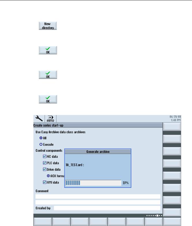
9. Press the "New directory" softkey to generate a new directory.
The "New Directory" window opens.
10.Enter the required name and confirm with "OK."
The directory is created subordinate to the selected folder. 11.Press the "OK" softkey.
The "Generate Archive: Name" window opens. 12.Enter the required name and confirm with "OK."
A file with format type *.ard is saved in the selected directory:
Figure 3-1 Generating an archive
Hardware and Software |
|
Service Manual, 03/2011, 6FC5397-5DP40-0BA0 |
29 |
Service cases - software
3.2 Generating a commissioning archive
3.2.2This is how you import a series commissioning archive from an external data carrier
Reading in an archive from an external data carrier
Procedure:
1.Select the "Start-up" operating area.
2.Press the menu forward key.
3.Press the "Series startup" softkey.
4.Press "OK".
The "Series Start-up" window opens.
5.Activate "Read in series startup".
6.Press "OK".
The "Select Startup Archive" window opens and the data tree is displayed.
|
Hardware and Software |
30 |
Service Manual, 03/2011, 6FC5397-5DP40-0BA0 |
 Loading...