


_
_
_
_
_
_
_
_
_
SINUMERIK SINUMERIK 840D sl/840Di sl/828D/802D sl ISO Milling
SINUMERIK
SINUMERIK 840D sl/840Di sl/ 828D/802D sl ISO Milling
Programming Manual
Principles of programming
_____________
Drive commands
_____________
Motion commands
_____________
Additional functions
_____________
Abbreviations
_____________
G code table
_____________
Data Description
_____________
Data lists
_____________
Interrupts
_____________
1
2
3
4
A
B
C
D
E
Valid for
Software Version
SINUMERIK 802D sl 1.4
SINUMERIK 828D 2.6
SINUMERIK 840D sl/DE sl 2.6
SINUMERIK 840Di sl/DiE sl 1.4
06/09
6FC5398-7BP10-1BA0
Legal information
Legal information
Warning notice system
This manual contains notices you have to observe in order to ensure your personal safety, as well as to prevent
damage to property. The notices referring to your personal safety are highlighted in the manual by a safety alert
symbol, notices referring only to property damage have no safety alert symbol. These notices shown below are
graded according to the degree of danger.
DANGER
indicates that death or severe personal injury will result if proper precautions are not taken.
WARNING
indicates that death or severe personal injury may result if proper precautions are not taken.
CAUTION
with a safety alert symbol, indicates that minor personal injury can result if proper precautions are not taken.
CAUTION
without a safety alert symbol, indicates that property damage can result if proper precautions are not taken.
NOTICE
indicates that an unintended result or situation can occur if the corresponding information is not taken into
account.
If more than one degree of danger is present, the warning notice representing the highest degree of danger will
be used. A notice warning of injury to persons with a safety alert symbol may also include a warning relating to
property damage.
Qualified Personnel
The device/system may only be set up and used in conjunction with this documentation. Commissioning and
operation of a device/system may only be performed by qualified personnel. Within the context of the safety notes
in this documentation qualified persons are defined as persons who are authorized to commission, ground and
label devices, systems and circuits in accordance with established safety practices and standards.
Proper use of Siemens products
Note the following:
WARNING
Siemens products may only be used for the applications described in the catalog and in the relevant technical
documentation. If products and components from other manufacturers are used, these must be recommended
or approved by Siemens. Proper transport, storage, installation, assembly, commissioning, operation and
maintenance are required to ensure that the products operate safely and without any problems. The permissible
ambient conditions must be adhered to. The information in the relevant documentation must be observed.
Trademarks
All names identified by ® are registered trademarks of the Siemens AG. The remaining trademarks in this
publication may be trademarks whose use by third parties for their own purposes could violate the rights of the
owner.
Disclaimer of Liability
We have reviewed the contents of this publication to ensure consistency with the hardware and software
described. Since variance cannot be precluded entirely, we cannot guarantee full consistency. However, the
information in this publication is reviewed regularly and any necessary corrections are included in subsequent
editions.
Siemens AG
Industry Sector
Postfach 48 48
90026 NÜRNBERG
GERMANY
Ordernumber: 6FC5398-7BP10-1BA0
Ⓟ 07/2009
Copyright © Siemens AG 2009.
Technical data subject to change

Table of contents
1 Principles of programming .........................................................................................................................
1.1 Introductory comments ..................................................................................................................
1.1.1 Siemens mode ...............................................................................................................................
1.1.2 ISO dialect mode ...........................................................................................................................
1.1.3 Switching between the modes .......................................................................................................
1.1.4 Display of the G code.....................................................................................................................
1.1.5 Maximum number of axes/axis identifiers......................................................................................
1.1.6 Decimal point programming...........................................................................................................
1.1.7 Comments....................................................................................................................................
1.1.8 Skip block.....................................................................................................................................
1.2 Preconditions for the feed............................................................................................................
1.2.1 Rapid traverse..............................................................................................................................
1.2.2 Path feed (F function) ..................................................................................................................
1.2.3 Fixed feedrates F0 to F9..............................................................................................................
1.2.4 Linear feed (G94).........................................................................................................................
1.2.5 Inverse-time feed (G93) ...............................................................................................................
1.2.6 Revolutional feedrate (G95).........................................................................................................
2 Drive commands......................................................................................................................................
2.1 Interpolation commands...............................................................................................................
2.1.1 Rapid traverse (G00) ...................................................................................................................
2.1.2 Linear interpolation (G01) ............................................................................................................
2.1.3 Circular interpolation (G02, G03).................................................................................................
2.1.4 Contour definition programming and addition of chamfers or radiuses.......................................
2.1.5 Helical interpolation (G02, G03)...................................................................................................
2.1.6 Involute interpolation (G02.2, G03.2)...........................................................................................
2.1.7 Cylindrical interpolation (G07.1)...................................................................................................
7
7
7
7
7
8
8
8
10
10
11
11
11
13
15
15
16
17
17
17
18
19
22
25
26
27
2.2 Reference point approach with G functions.................................................................................
2.2.1 Reference point approach with intermediate point (G28)............................................................
2.2.2 Checking the reference position (G27) ........................................................................................
2.2.3 Reference point approach with reference point selection (G30) .................................................
3 Motion commands ...................................................................................................................................
3.1 The coordinate system.................................................................................................................
3.1.1 Machine coordinate systems (G53) .............................................................................................
3.1.2 Workpiece coordinate system (G92) ...........................................................................................
3.1.3 Resetting the tool coordinate system (G92.1) .............................................................................
3.1.4 Selection of a workpiece coordinate system................................................................................
3.1.5 Writing work offset/tool offsets (G10)...........................................................................................
3.1.6 Local coordinate system (G52)....................................................................................................
3.1.7 Selection of the plane (G17, G18, G19) ......................................................................................
3.1.8 Parallel axes (G17, G18, G19).....................................................................................................
3.1.9 Rotation of the coordinate system (G68, G69) ............................................................................
3.1.10 3D rotation G68/G69....................................................................................................................
3.2 Defining the input modes of the coordinate values......................................................................
3.2.1 Absolute/incremental dimensioning (G90, G91) ..........................................................................
3.2.2 Inch/metric input (G20, G21)........................................................................................................
ISO Milling
Programming Manual, 06/09, 6FC5398-7BP10-1BA0
30
30
32
33
35
35
36
37
38
38
38
40
41
42
43
45
46
46
47
3

Table of contents
3.2.3 Scaling (G50, G51) ..................................................................................................................... 48
3.2.4 Programmable mirroring (G50.1, G51.1) ....................................................................................
51
3.3 Time-controlled commands.........................................................................................................
3.3.1 Dwell time (G04) .........................................................................................................................
3.4 Tool offset functions ....................................................................................................................
3.4.1 Tool offset data memory .............................................................................................................
3.4.2 Tool length compensation (G43, G44, G49)...............................................................................
3.4.3 Cutter radius compensation (G40, G41, G42) ............................................................................
3.4.4 Collision detection .......................................................................................................................
3.5 S-, T-, M- and B functions ...........................................................................................................
3.5.1 Spindle function (S function) .......................................................................................................
3.5.2 Tool function................................................................................................................................
3.5.3 Additional function (M function)...................................................................................................
3.5.4 M functions of spindle control......................................................................................................
3.5.5 M functions for subroutine calls ..................................................................................................
3.5.6 Macro call via M function.............................................................................................................
3.5.7 M functions..................................................................................................................................
3.6 Controlling the feedrate...............................................................................................................
3.6.1 Automatic corner override G62 ...................................................................................................
3.6.2 Compressor in the ISO dialect mode ..........................................................................................
3.6.3 Exact stop (G09, G61), Continuous-path mode (G64), tapping (G63) .......................................
4 Additional functions..................................................................................................................................
4.1 Program supporting functions .....................................................................................................
4.1.1 Fixed drilling cycles .....................................................................................................................
4.1.2 Deep hole drilling cycle with chip breakage (G73)......................................................................
4.1.3 Fine drilling cycle (G76) ..............................................................................................................
4.1.4 Drilling cycle, preboring (G81) ....................................................................................................
4.1.5 Drilling cycle, preboring (G82) ....................................................................................................
4.1.6 Deep hole drilling cycle with chip removal (G83)........................................................................
4.1.7 Drilling cycle (G85)......................................................................................................................
4.1.8 Boring cycle (G86) ......................................................................................................................
4.1.9 Boring cycle, reverse countersinking (G87)................................................................................
4.1.10 Drilling cycle (G89), return with G01...........................................................................................
4.1.11 Cycle "Tapping without compensating chuck" (G84) ..................................................................
4.1.12 "Drilling a left-hand thread without compensating chuck" cycle (G74) .....................................
4.1.13 Left or right tapping cycle (G84 or G74)....................................................................................
4.1.14 Deselection of a fixed cycle (G80) ............................................................................................
4.1.15 Program example with a tool length compensation and fixed cycles .......................................
4.1.16 Multiple-start threads with G33 .................................................................................................
53
53
54
54
54
57
61
65
65
65
65
66
67
67
68
69
69
71
72
73
73
73
78
81
84
85
87
90
91
93
96
98
101
103
106
107
109
4.2 Programmable data input (G10) ...............................................................................................
4.2.1 Changing the tool offset value...................................................................................................
4.2.2 Working area limitation (G22, G23) ..........................................................................................
4.2.3 M function for calling subroutines (M98, M99)..........................................................................
4.3 Eight-digit program number.......................................................................................................
4.4 Polar coordinates (G15, G16) ...................................................................................................
4.5 Polar coordinates interpolation (G12.1, G13.1) ........................................................................
4.6 Measuring functions ..................................................................................................................
4.6.1 Rapid lift with G10.6 ..................................................................................................................
4.6.2 Measuring with "delete distance-to-go" (G31) ..........................................................................
4.6.3 Measuring with G31, P1 - P4 ....................................................................................................
ISO Milling
110
110
110
111
113
115
116
118
118
118
121
4 Programming Manual, 06/09, 6FC5398-7BP10-1BA0

Table of contents
4.6.4 Interrupt program with M96, M97...............................................................................................122
4.6.5 "Tool life control" function ..........................................................................................................
124
4.7 Macro programs.........................................................................................................................
4.7.1 Differences with subroutines......................................................................................................
4.7.2 Macro program call (G65, G66, G67) ........................................................................................
4.7.3 Macro call via G function............................................................................................................
4.8 Special functions........................................................................................................................
4.8.1 Contour repetition (G72.1, G72.2) .............................................................................................
4.8.2 Switchover modes for DryRun and skip levels ..........................................................................
A Abbreviations.........................................................................................................................................
B G code table ..........................................................................................................................................
C Data Description....................................................................................................................................
C.1 General machine data................................................................................................................
C.2 Channel-specific machine data..................................................................................................
C.3 Axis-specific setting data ...........................................................................................................
C.4 Channel-specific setting data.....................................................................................................
D Data lists................................................................................................................................................
D.1 Machine data..............................................................................................................................
D.2 Setting data................................................................................................................................
D.3 Variables ....................................................................................................................................
E Interrupts ...............................................................................................................................................
125
125
125
132
135
135
137
139
147
151
151
164
177
178
181
181
183
184
187
Glossary ................................................................................................................................................
Index......................................................................................................................................................
189
213
ISO Milling
Programming Manual, 06/09, 6FC5398-7BP10-1BA0
5

Table of contents
ISO Milling
6 Programming Manual, 06/09, 6FC5398-7BP10-1BA0

Principles of programming
1.1 Introductory comments
1.1.1 Siemens mode
The following conditions are valid in the Siemens mode:
● The default of the G commands can be defined for each channel via the machine data
20150 $MC_GCODE_RESET_VALUES.
● No language commands from the ISO dialects can be programmed in the Siemens mode.
1.1.2 ISO dialect mode
The following conditions are valid in the active ISO dialect mode:
● The ISO dialect mode can be set with machine data as the default setting of control
system. The control system reboots by default in the ISO dialect mode subsequently.
● Only G functions from the ISO dialect can be programmed; the programming of Siemens
G functions is not possible in the ISO Mode.
1
● Mixing of ISO dialect and Siemens language in the same NC block is not possible.
● Switching between ISO Dialect M and ISO Dialect T with a G command is not possible.
● Subroutines that are programmed in the Siemens mode can be called.
● If Siemens functions are to be used, one must first switch to the Siemens mode.
1.1.3 Switching between the modes
The following G functions can be used to switch between the Siemens mode and the ISO
dialect mode:
● G290 - Siemens NC programming language active
● G291 - ISO Dialect NC Programming language active
The active tool, the tool offsets and work offsets are not influenced by the switchover.
G290 and G291 must be programmed alone in an NC block.
ISO Milling
Programming Manual, 06/09, 6FC5398-7BP10-1BA0
7

Principles of programming
1.1 Introductory comments
1.1.4 Display of the G code
The G code is displayed in the same language (Siemens or ISO Dialect) as the relevant
current block. If the display of the blocks is suppressed with DISPLOF, the G codes continue
to be displayed in the language in which the active block is displayed.
Example
The G functions of the ISO dialect mode are used to call the Siemens standard cycles. To do
this, DISPLOF is programmed at the start of the relevant cycle; this way the G functions that
are programmed in the ISO dialect language continue to be displayed.
PROC CYCLE328 SAVE DISPLOF
N10 ...
...
N99 RET
Procedure
The Siemens shell cycles are called via main programs. The Siemens mode is selected
automatically by calling the shell cycle.
With DISPLOF, the block display is frozen on calling the cycle; the display of the G code
continues in the ISO Mode.
The G codes that were changed in the shell cycle, are reset to their original status at the end
of the cycle with the "SAVE" attribute.
1.1.5 Maximum number of axes/axis identifiers
The maximum number of axes in the ISO dialect mode is 9. The axis identifiers for the first
three axes are defined permanently with X, Y and Z. All other axes can be identified with the
letters A, B, C, U, V and W.
1.1.6 Decimal point programming
In the ISO dialect mode, there are two notations for evaluating programmed values without
decimal point:
● Pocket calculator notation
Values without decimal points are interpreted as mm, inch or degree.
● Standard notation
Values without decimal point are multiplied by a conversion factor.
The setting is done over MD10884 $MN_EXTERN_FLOATINGPOINT_PROG.
There are two different conversion factors, IS-B and IS-C. This weighting is related to the
addresses X Y Z U V W A B C I J K Q R and F.
Example:
Linear axis in mm:
ISO Milling
8 Programming Manual, 06/09, 6FC5398-7BP10-1BA0

Principles of programming
1.1 Introductory comments
● X 100.5
corresponds to a value with decimal point: 100.5 mm
● X 1000
– Pocket calculator notation: 1,000 mm
– Standard notation:
IS-B: 1,000* 0.001= 1 mm
IS-C: 1,000* 0.0001= 0.1 mm
ISO dialect milling
Table 1- 1 Different conversion factors for IS-B and IS-C
Address Unit IS-B IS-C
Linear axis mm
inch
Rotary axis Degree 0,001 0,0001
F feed G94 (mm/inch per min.) mm
inch
F feed G95 (mm/inch per min.) mm
inch
F thread lead mm
inch
C chamfer mm
inch
R radius, G10 toolcorr mm
inch
Q mm
inch
I, J, K IPO parameters mm
inch
G04 X or U s 0,001 0,001
A angle contour definition Degree 0,001 0,0001
G74, G84 tapping cycles
$MC_EXTERN_FUNCTION_MASK
Bit8 = 0 F as feed such as G94, G95
Bit8 = 1 F as thread lead
0,001
0,0001
1
0,01
0,01
0,0001
0,01
0,0001
0,001
0,0001
0,001
0,0001
0,001
0,0001
0,001
0,0001
0,0001
0,00001
1
0,01
0,01
0,0001
0,01
0,0001
0,0001
0,00001
0,0001
0,00001
0,0001
0,00001
0,0001
0,00001
ISO Milling
Programming Manual, 06/09, 6FC5398-7BP10-1BA0
9

Principles of programming
1.1 Introductory comments
1.1.7 Comments
In the ISO dialect mode, brackets are interpreted as comment signs. In the Siemens mode,
";" is interpreted as comment. To simplify matters, an ";" is also understood as comment in
the ISO dialect mode.
If the comment start sign '(' is used inside a comment again, the comment is ended only if all
the open brackets are closed again.
Example:
N5 (comment) X100 Y100
N10 (comment(comment)) X100 Y100
N15 (comment(comment) X100) Y100
X100 Y100 is executed in block N5 and N10, but only Y100 in block N15, because the first
bracket is closed only after X100. Everything up to that point is interpreted as comment.
1.1.8 Skip block
The sign of skipping or suppression of blocks "/" can be used at any convenient position in a
block, i.e. even in the middle of the block. If the programmed block skip level is active on the
date of the compilation, the block is not compiled from this point up to the end of the block.
An active block skip level has the same effect as a block end.
Example:
N5 G00 X100. /3 YY100 --> Alarm 12080 "Syntax error"
N5 G00 X100. /3 YY100 --> no alarm, if block skip level 3 is active
Block skip signs within a comment are not interpreted as block skip signs
Example:
N5 G00 X100. ( /3 Part1 ) Y100
;the Y axis is traversed even when the block skip level 3 is active
The block skip levels /1 to /9 can be active. Block skip values <1 and >9 lead to alarm 14060
"Impermissible skip level for differential block skip".
The function is mapped to the existing Siemens skip levels. Unlike the ISO Dialect original,
"/" and "/1" are separate skip levels that must also be activated separately.
Note
The "0" in "/0" can be omitted.
ISO Milling
10 Programming Manual, 06/09, 6FC5398-7BP10-1BA0

Principles of programming
1.2 Preconditions for the feed
1.2 Preconditions for the feed
The following Section describes the feed function with which the feedrate (covered path per
minute or per rotation) of a cutting tool is defined.
1.2.1 Rapid traverse
Rapid traverse is used for positioning (G00) as well as for manual traverse with rapid
traverse (JOG). In rapid traverse, each axis is traversed with the rapid traverse rate set for
the individual axes. The rapid traversing rate is defined by the machine manufacturer and it
is specified by the machine data for the individual axes. As the axes traverse independently
of each other, each axis reaches its target point at a different time. Hence, the resulting tool
path is generally not a straight line.
1.2.2 Path feed (F function)
Note
Unless something else is specified, the unit "mm/min" always stands for feedrate of the
cutting tool in this documentation.
The feed with which a tool should be traversed in linear interpolation (G01) or circular
interpolation (G02, G03) is designated with the address character "F".
The feed of the cutting tool in "mm/min" is specified after the address character "F".
The permissible range of F values is specified in the documentation of the machine
manufacturer.
Possibly, the feed is limited by the servo system and the mechanical system in the upward
direction. The maximum feed is set in the machine data and limited to the value defined
there before an overshoot.
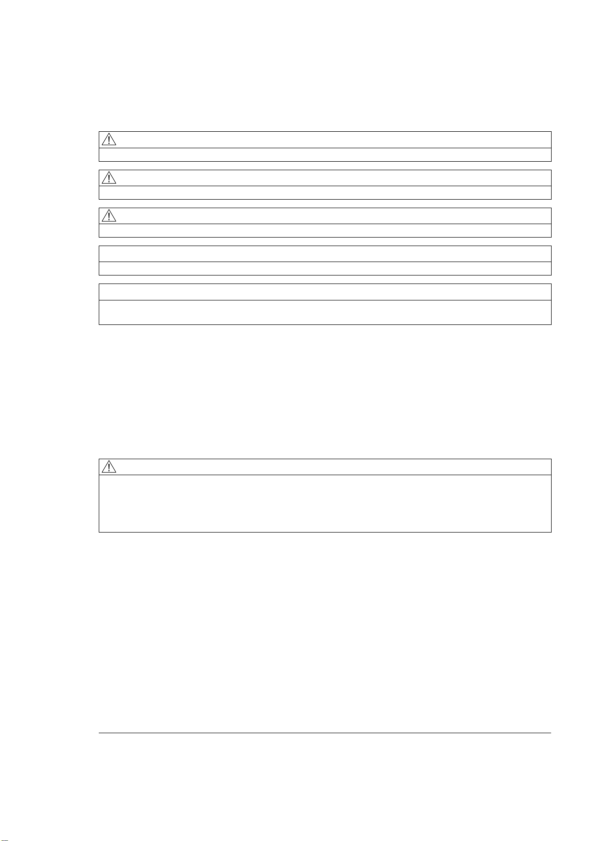
The path feed is generally composed of the individual speed components of all geometry
axes participating in the movement and refers to the cutter center (see the two following
figures).
ISO Milling
Programming Manual, 06/09, 6FC5398-7BP10-1BA0
11
Principles of programming
1.2 Preconditions for the feed
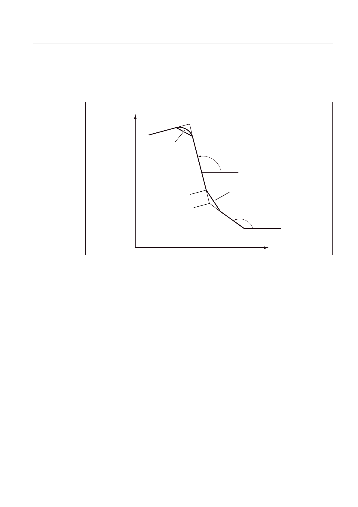
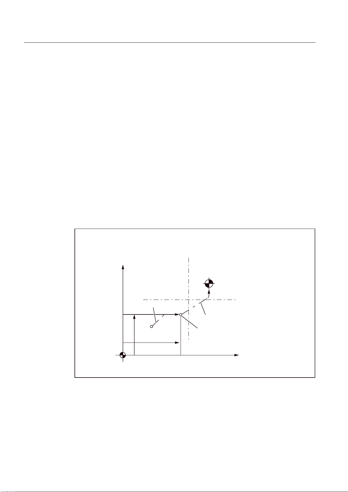
3URJUDPPLQJH[DPSOHZLWKWKH
IROORZLQJSURJUDP
*,QFUHPHQWDOGLPHQVLRQLQJ
*;<)
3DWKYHORFLW\LQ
WDQJHQWLDOGLUHFWLRQ
PPPLQ
Figure 1-1 Linear interpolation with 2 axes
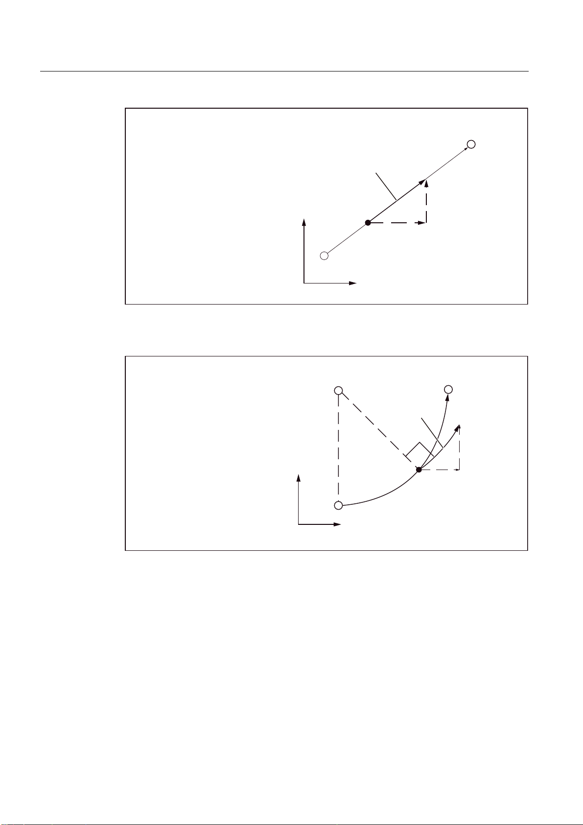
3URJUDPPLQJH[DPSOHZLWKWKH
IROORZLQJSURJUDP
*,QFUHPHQWDOGLPHQVLRQLQJ
*;<,)
<
<
PPPLQ
PPPLQ
;
&HQWHUSRLQW
PPPLQ
)\
)[
;
Figure 1-2 Circular interpolation with 2 axes
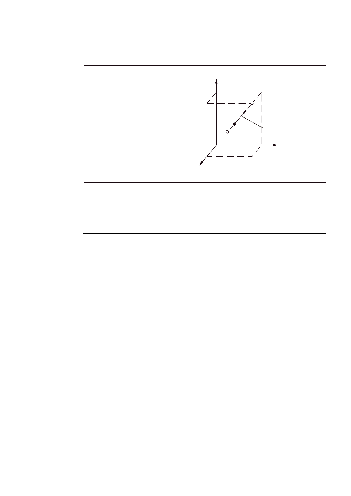
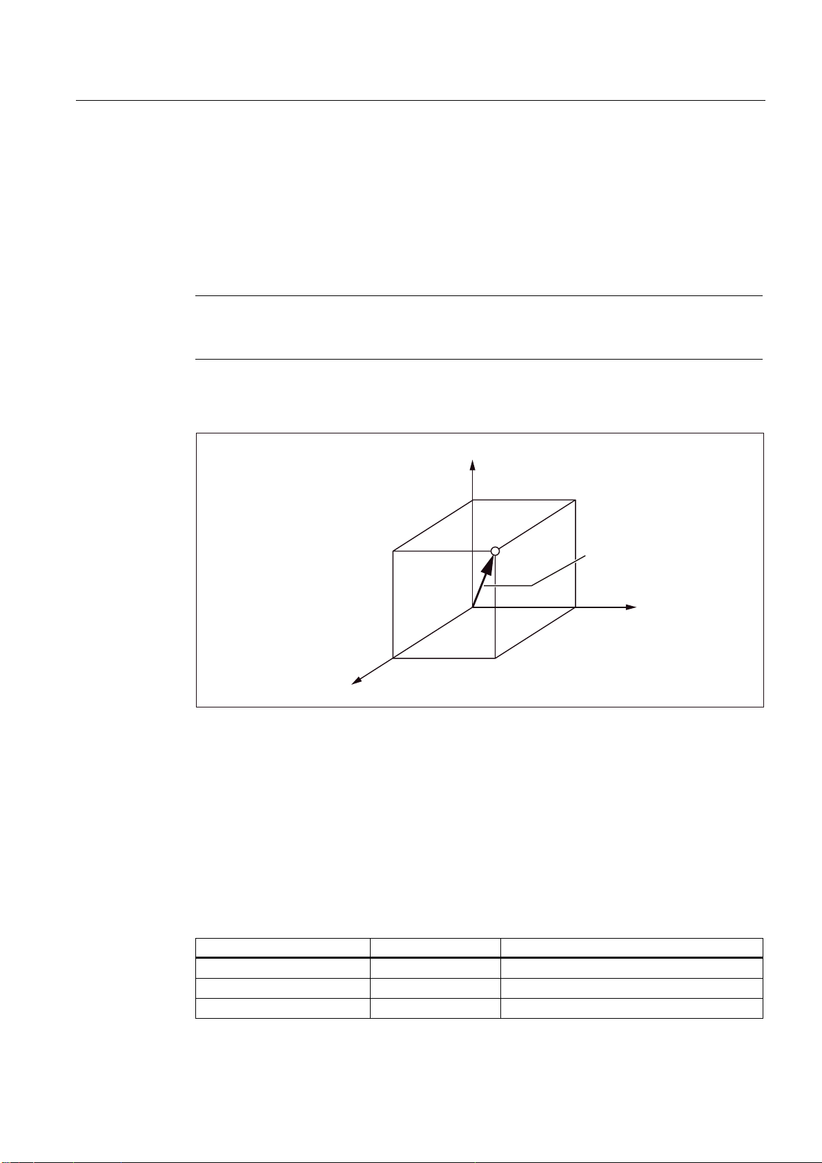
In 3D interpolation, the feed of the resulting straight lines programmed with F are maintained
in the space.
ISO Milling
12 Programming Manual, 06/09, 6FC5398-7BP10-1BA0
Principles of programming
1.2 Preconditions for the feed
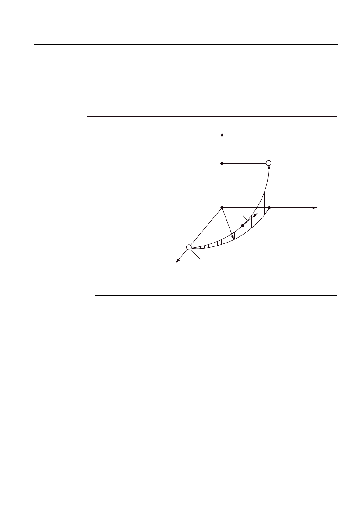
3URJUDPPLQJH[DPSOHZLWK
WKHIROORZLQJSURJUDP
*;<=)
=
<
(QGSRLQW
PPPLQ
6WDUWSRLQW
;
Figure 1-3 Feed in case of 3D interpolation
Note
If "F0" is programmed and the function "Fixed feedrate" is not active, then the Alarm 14800
"Programmed path velocity less than or equal to zero" is output.
1.2.3 Fixed feedrates F0 to F9
Activate feed values
Ten different feed values pre-set via setting data can be activated with F0 to F9. To activate
the rapid traverse rate with F0, the corresponding speed must be entered in the setting data
42160 $SC_EXTERN_FIXED_FEEDRATE_F1_F9[0].
The feed values for F0 to F9 are entered in the setting data as real values. An evaluation of
the input values is not undertaken.
The function is activated via the machine data 22920
$MC_EXTERN_FIXED_FEEDRATE_F1_ON. If the machine data is set to FALSE, F1 - F9 is
interpreted as normal feed programming, e.g. F2 = 2 mm/min, F0=0 mm/min.
If the machine data = TRUE, the feed values for F0 - F9 are fetched from the setting data
42160 $SC_EXTERN_FIXED_FEEDRATE_F1_F9[ ]. If the value 0 exists in one of the
setting data, then the corresponding address extension of feed 0 is activated during the
programming.
ISO Milling
Programming Manual, 06/09, 6FC5398-7BP10-1BA0
13

Principles of programming
1.2 Preconditions for the feed
Example
$SC_FIXED_FEEDRATE_F1_F9[0] = 5000
$SC_FIXED_FEEDRATE_F1_F9[1] = 1000
$SC_FIXED_FEEDRATE_F1_F9[2] = 500
N10 X10 Y10 Z10 F0 G94 ;Approach position at 5000 mm/min
N20 G01 X150 Y30 F1 ;Feed 1000 mm/min active
N30 Z0 F2 ;Position approached at 500 mm/min
N40 Z10 F0 ;Approach position at 5000 mm/min
Table 1- 2 Setting data for the default setting of feedrate F
F function Setting Data
F0 $SC_EXTERN_FIXED_FEEDRATE_F1_F9[0]
F1 $SC_EXTERN_FIXED_FEEDRATE_F1_F9[1]
F2 $SC_EXTERN_FIXED_FEEDRATE_F1_F9[2]
F3 $SC_EXTERN_FIXED_FEEDRATE_F1_F9[3]
F4 $SC_EXTERN_FIXED_FEEDRATE_F1_F9[4]
F5 $SC_EXTERN_FIXED_FEEDRATE_F1_F9[5]
F6 $SC_EXTERN_FIXED_FEEDRATE_F1_F9[6]
F7 $SC_EXTERN_FIXED_FEEDRATE_F1_F9[7]
F8 $SC_EXTERN_FIXED_FEEDRATE_F1_F9[8]
F9 $SC_EXTERN_FIXED_FEEDRATE_F1_F9[9]
Note: Input format = REAL
Note
If the function is activated with MD $MC_EXTERN_FIXED_FEEDRATE_F1_ON and if the
feed value from the setting data is not to be active with F1 to F9, then the feed value is
programmed as actual value. If, for instance, a feed value should be programmed at 1
mm/min, the feed must be programmed with F1.0 instead of F1.
If the "DRY RUN" (test run) switch is set to "ON", all the feed commands are traversed at the
feed set for the test run.
The Feed Override function is effective even for the fixed feedrates F0 to F9.
The feed set in the setting data is stored even after the control system is switched off.
In a macro call with G65/G66, the value programmed with F is stored in the system variable
$C_F, i.e. the numeric values 0 to 9 are stored.
If, in a cycle call, a fixed feed (F0 - F9) is programmed in a machining program, the feed
value is read from the relevant setting data and stored in the variable $C_F.
ISO Milling
14 Programming Manual, 06/09, 6FC5398-7BP10-1BA0

Principles of programming
1.2 Preconditions for the feed
Example
$SC_FIXED_FEEDRATE_F1_F9[0] = 1500.0
$SC_FIXED_FEEDRATE_F1_F9[1] = 550.0
N10 X10 Y10 Z10 F0 G94 ;Positioning with 1500
N20 G01 X150 Y30 F1 ;Feed 550 mm/min active
N40 Z10 F0 ;Positioning with 1500
Note
While macroprogramming with G65/66, the programmed value for the address F is always
stored in the cycle system variable. For F1 to F9, for example, the value 1 to 9 is entered in
the cycle system variable $C_F. The address signifies a transfer variable here and has no
direct reference to the feed.
The same is true of the thread lead programming in G33 - G34 with the address F. No feed
is programmed with F here, instead the distance between two threads during a spindle
revolution.
In cycle programming (e.g., G81 X.. Y.. Z.. R.. P.. Q.. F..), the feed is always programmed
under the address F. In a part program block with a cycle call over a G function (G81 - G87
etc.), the corresponding feed value during the programming of F1 to F9 is written from the
corresponding setting data in the variable $C_F.
Restriction
In the ISO dialect mode, the feed values are changed in the setting data with a handwheel.
In the Siemens mode, the feeds can be influenced only like a directly programmed feed, e.g.
through the override switch.
1.2.4 Linear feed (G94)
On specifying G94, the feed given after the address character F is executed in the mm/min,
inch/min or degree/min unit.
1.2.5 Inverse-time feed (G93)
On specifying G93, the feed given after the address character F is executed in the 1/min
unit. G93 is a modally effective G function.
Example
N10 G93 G1 X100 F2 ;
ISO Milling
Programming Manual, 06/09, 6FC5398-7BP10-1BA0
15

Principles of programming
1.2 Preconditions for the feed
Note
The time inverse feed 1/min G93 is not implemented for SINUMERIK 802D.
i.e., the programmed path is traversed within half a minute.
1.2.6 Revolutional feedrate (G95)
On entering G95, the feed is executed in the mm/revolution unit or inch/revolution related to
the master spindle.
Note
All of the commands are modal. If the G feed command is switched among G93, G94 or
G95, the path feed must be reprogrammed. The feed can also be specified in
degree/revolution for the machining with rotary axes.
ISO Milling
16 Programming Manual, 06/09, 6FC5398-7BP10-1BA0

Drive commands
2.1 Interpolation commands
The positioning and interpolation commands, with which the tool path along the programmed
contour, such as a straight line or a circular arc, is monitored, are described in the next
Section.
2.1.1 Rapid traverse (G00)
You can use rapid traverse to position the tool rapidly, to traverse around the workpiece or to
approach tool change points.
The following G functions can be used to call the positioning (refer to following table):
Table 2- 1 G function for positioning
G function Function G group
G00 Rapid traverse 01
G01 Linear movement 01
G02 Circle/helix in the clockwise direction 01
G02.2 Involute in the clockwise direction 01
G03 Circle/helix in the counterclockwise direction 01
G03.2 Involute in the counterclockwise direction 01
2
Positioning (G00)
Format
G00 X... Y... Z... ;
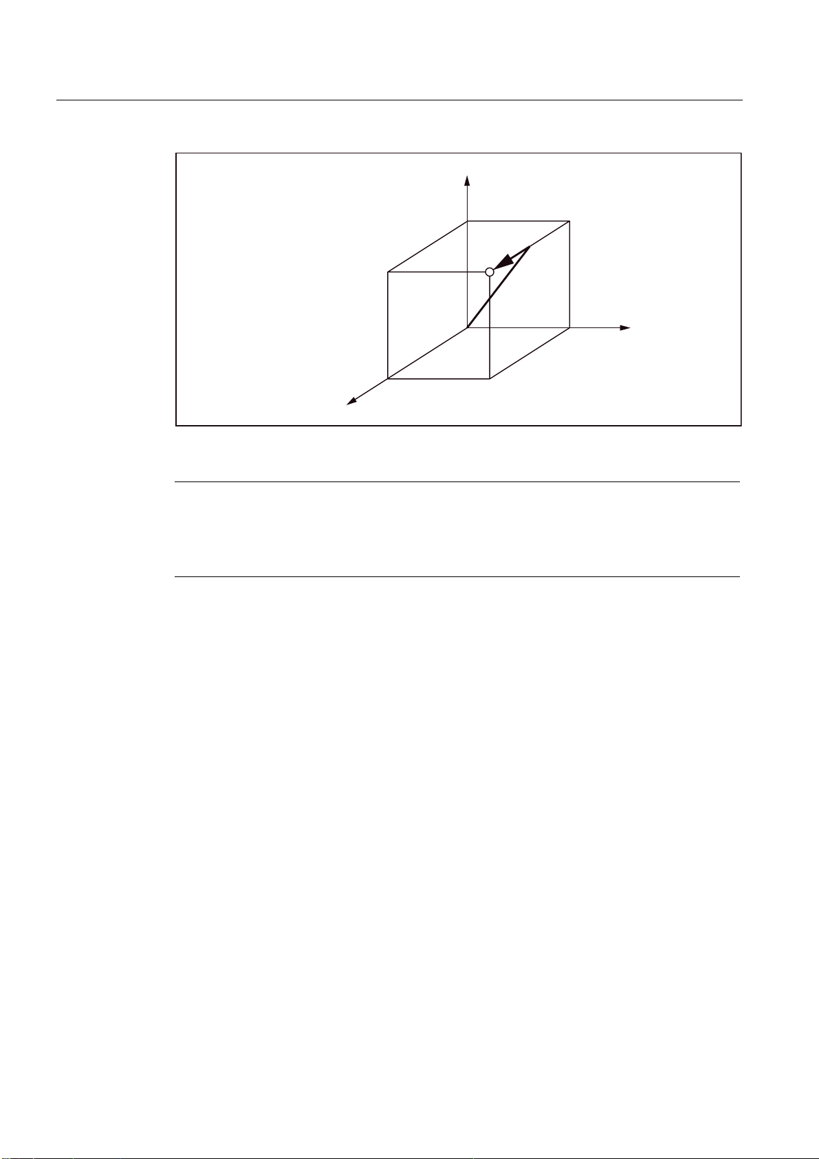
Explanation
The tool movement programmed with G00 is executed at the highest possible traversing
speed (rapid traverse). The rapid traverse rate is defined separately for each axis in machine
data. If the rapid traverse movement is executed simultaneously on several axes, the rapid
traverse rate is determined by the axis which requires the most time for its section of the
path.
Axes that are not programmed in a G00 block are not traversed. In positioning, the individual
axes traverse independently of each other with the rapid traverse rate specified for each
axis. The precise speeds of your machine can be consulted in the documentation of the
manufacturer.
ISO Milling
Programming Manual, 06/09, 6FC5398-7BP10-1BA0
17
Drive commands
2.1 Interpolation commands
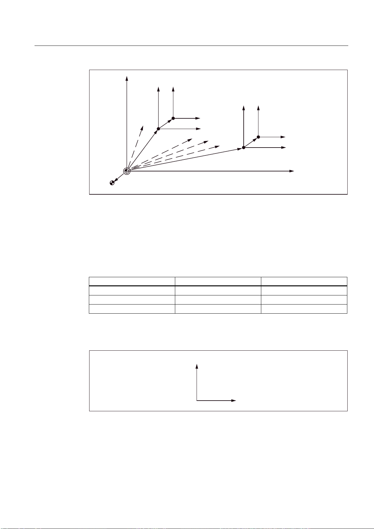
3URJUDPPLQJH[DPSOH
*;<=
=D[LV
<D[LV
5DSLGWUDYHUVHUDWH
;D[LVPPPLQ
<D[LVPPPLQ
=D[LVPPPLQ
;D[LV
Figure 2-1 Positioning in the run state with 3 simultaneously controllable axes
Note
As in positioning with G00, the axes traverse independently of each other (not interpolated),
each axis reaches its end point at a different time. Hence, one must be very careful in
positioning with several axes, so that a tool does not collide with a workpiece of the tool
during the positioning.
Linear interpolation (G00)
Linear interpolation with G00 is defined by setting the machine data 20732
$MC_EXTERN_GO_LINEAR_MODE. Here, all programmed axes traverse in rapid traverse
with linear interpolation and reach their target positions simultaneously.
2.1.2 Linear interpolation (G01)
With G01 the tool travels on paraxial, inclined or straight lines arbitrarily positioned in space.
Linear interpolation permits machining of 3D surfaces, grooves, etc.
Format
G01 X... Y... Z... F... ;
In G01, the linear interpolation is executed with the path feed. The axes that are not
specified in the block with G01 are not traversed. The linear interpolation is programmed as
in the example given above.
ISO Milling
18 Programming Manual, 06/09, 6FC5398-7BP10-1BA0
Drive commands
A
2.1 Interpolation commands
Feed F for path axes
The feedrate is specified under the address F. Depending on the default setting in the
machine data, the units of measurement specified with the G commands (G93, G94, G95)
are either in mm or inch.
One F value can be programmed per NC block. The unit of feedrate is defined over one of
the mentioned G commands. The feed F acts only on path axes and remains active until a
new feed value is programmed. Separators are permitted after address F.
Note
n alarm is triggered while executing a G01 block if no feed was programmed in a block with
G01 or in the previous blocks.
The end point can be specified either as absolute or as incremental. Details are available in
Chapter "Absolute/incremental dimensioning".
3URJUDPPLQJH[DPSOH
*;<=)
=D[LV
Figure 2-2 Linear interpolation
<D[LV
PPPLQ
7DQJHQWLDOYHORFLW\
;D[LV
2.1.3 Circular interpolation (G02, G03)
Format
To start the circular interpolation, please execute the commands specified in the following
table.
Table 2- 2 Commands to be executed for circular interpolation
Element Command Description
Designation of the plane G17 Circular arc in Plane X-Y
G18 Circular arc in Plane Z-X
G19 Circular arc in Plane Y-Z
ISO Milling
Programming Manual, 06/09, 6FC5398-7BP10-1BA0
19
Drive commands
2.1 Interpolation commands
Element Command Description
Direction of rotation G02 clockwise
G03 counterclockwise
End-point position Two axes from X, Y
or Z
Two axes from X, Y
or Z
Distance between start point center
Radius of circular arc R Radius of circular arc
Feed F Speed along the circular arc
Two axes from I, J or K Distance start point - circle center with sign
End-point position in a workpiece coordinate
system
Distance of start point - end point with sign
Designation of the plane
With the commands specified below, a tool traverses along the specified circular arc in the
plane X-Y, Z-X or Y-Z, so that the feed specified with "F" is maintained on the circular arc.
● in Plane X-Y:
G17 G02 (or G03) X... Y... R... (or I... J... ) F... ;
● in Plane Z-X:
G18 G02 (or G03) Z... X... R... (or K... I... ) F... ;
● in the Plane Y-Z:
G19 G02 (or G03) Y... Z... R... (or J... K... ) F... ;
Before the circle radius programming (with G02, G03), one must first select the desired
interpolation plane with G17, G18 or G19. Circular interpolation is not allowed for the 4th and
5th axes, if these are linear axes.
Plane selection is also used to select the plane in which the tool radius compensation
(G41/G42) is performed. The Plane X-Y (G17) is automatically set after activating the control
system.
G17 X-Y plane
G18 Z-X plane
G19 Y-Z plane
The working planes should be specified, in general.
Circles can also be created outside the selected working plane. In this case, the axis
addresses (specification of circle end positions) determine the circular plane.
Circular interpolation is possible in the Xβ, Zβ or Yβ plane while selecting an optional 5th
linear axis, which also contains a 5th axis besides the X-Y, Y-Z and Z-X planes (β=U, V or
W)
● Circular interpolation in the Xβ plane
G17 G02 (or G03) X... β... R... (or I... J... ) F... ;
● Circular interpolation in the Zβ plane
G18 G02 (or G03) Z... β... R... (or K... I... ) F... ;
ISO Milling
20 Programming Manual, 06/09, 6FC5398-7BP10-1BA0
Drive commands
2.1 Interpolation commands
● Circular interpolation in the Yβ plane
G19 G02 (or G03) Y... β... R... (or J... K... ) F... ;
● If the address characters for the 4th and 5th axes are omitted - such as in the commands
"G17 G02 X... R... (or I... J... ) F... ;", then the X-Y plane is selected automatically as the
interpolation plane. Circular interpolation with the 4th and 5th axes is not possible if these
additional axes are rotary axes.
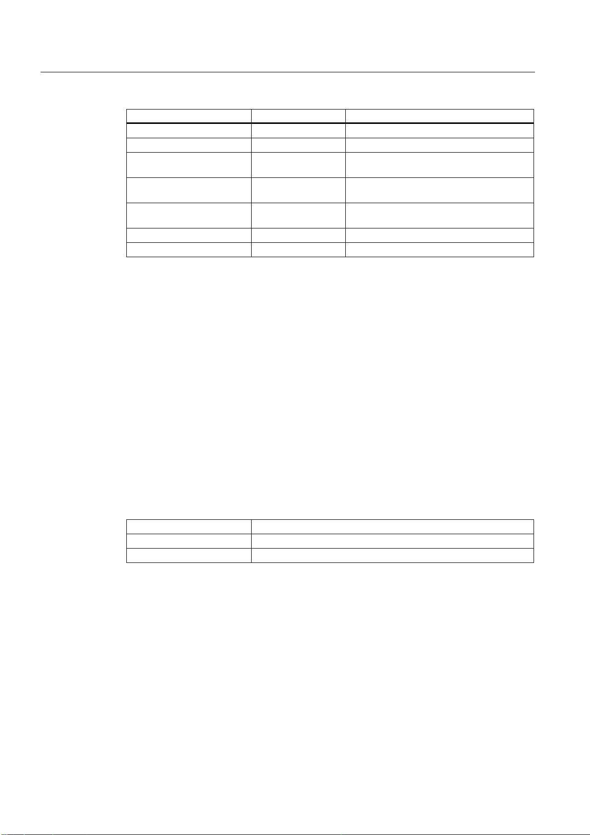
Direction of rotation
The direction of rotation of the circular arc is to be specified as given in the following figure.
G02 clockwise
G03 counterclockwise
<D[LV =D[LV
*
*
3ODQH;<* 3ODQH=;*
Figure 2-3 Direction of rotation of the circular arc
;D[LV =D[LV <D[LV
End point
The end point can be specified corresponding to the definition with G90 or G91 as absolute
or incremental (not in G Code System A!).
If the specified end point does not lie on the circular arc, the system outputs Alarm 14040
"Error in end point of circle".
Possibilities of programming circular movements
The control system offers two options of programming circular movements.
;D[LV
*
*
*
*
3ODQH<=*
The circular motion is described by the:
ISO Milling
Programming Manual, 06/09, 6FC5398-7BP10-1BA0
21
Drive commands
2.1 Interpolation commands
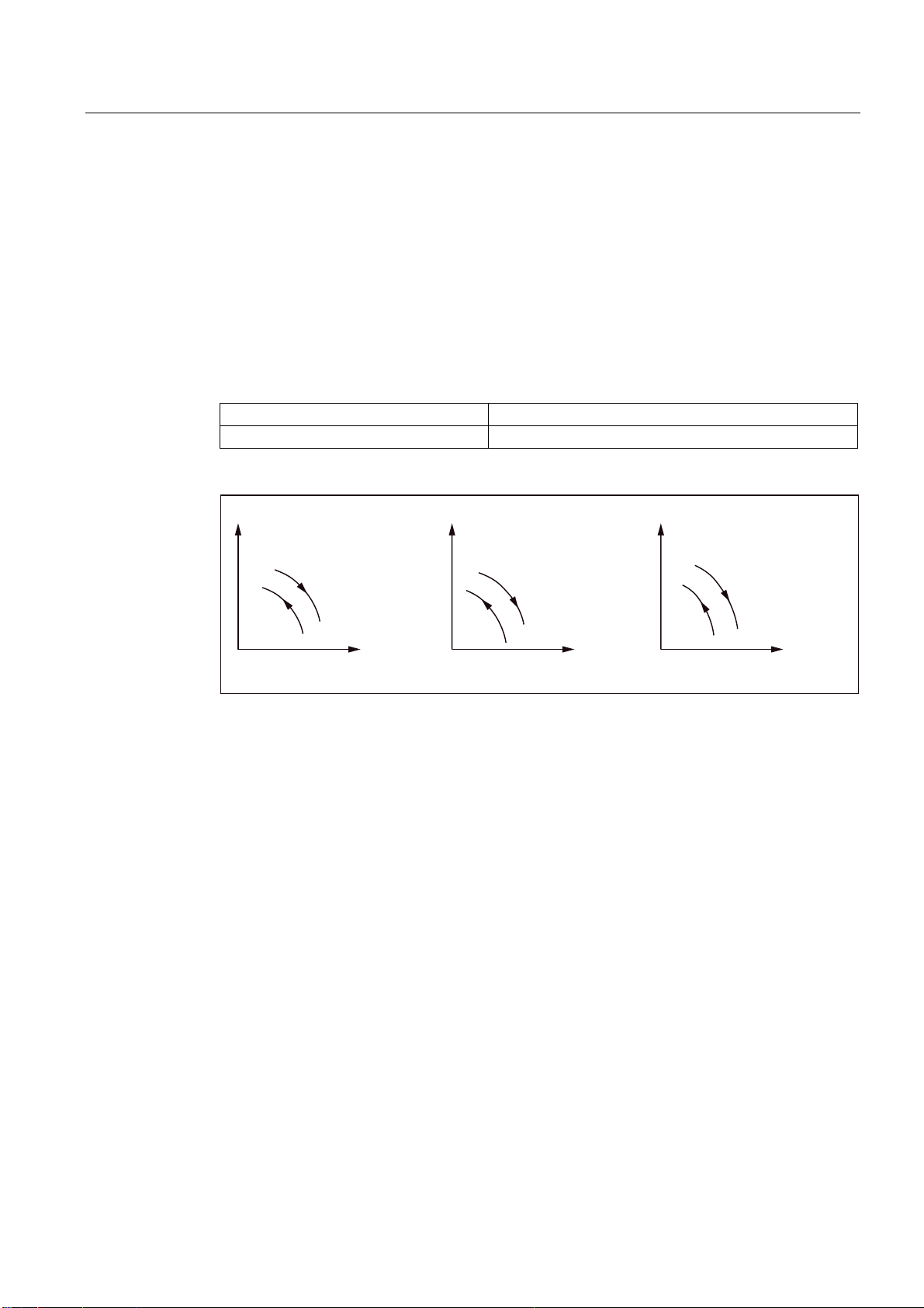
● Center point and end point in the absolute or incremental dimension (default)
● Radius and end point in Cartesian coordinates
For a circular interpolation with a central angle <= 180 degree, the programming should
be "R > 0" (positive).
For a circular interpolation with a central angle > 180 degree, the programming should be
"R < 0" (negative).
3URJUDPPLQJH[DPSOH
**;<5s)
rRUJUHDWHU
(QGSRLQW
rRUOHVVHU
5
5!
6WDUWSRLQW
Figure 2-4 Circular interpolation with specification of Radius R
Feed
During the circular interpolation, the feed can be specified exactly as during linear
interpolation (see Chapter "Linear interpolation (G01)").
2.1.4 Contour definition programming and addition of chamfers or radiuses
Chamfers or radiuses can be added after each traversing block between linear and circular
contours. For example, to grind sharp edges of workpieces.
The following combinations are possible during addition:
● between two straight lines
● between two circular arcs
● between a circular arc and a straight line
● between a straight line and a circular arc
Format
, C...; Chamfer
, R...; Rounding
ISO Milling
22 Programming Manual, 06/09, 6FC5398-7BP10-1BA0
Drive commands
2.1 Interpolation commands
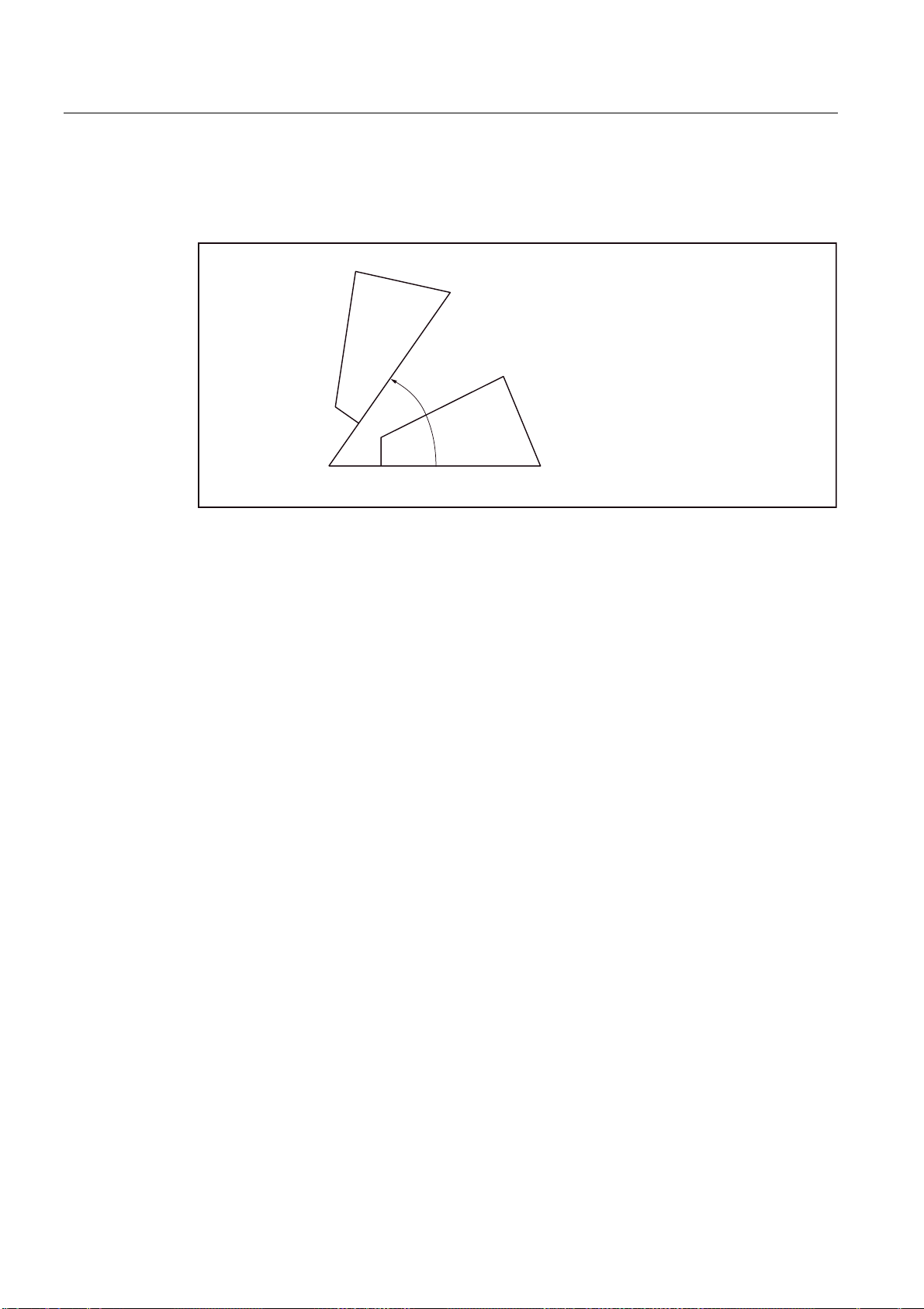
Example
N10 G1 X10. Y100. F1000 G18
N20 A140 C7.5
N30 X80. Y70. A95.824, R10
;
;=
;=
ISO dialect mode
5DGLXV
&KDPIHU
;=
Figure 2-5 3 straight lines
r
5
r
;=
=
In the ISO dialect original, the C address can be used as axis name as well as for denoting a
chamfer on the contour.
The Address R can either be a cycle parameter or an identifier of the radius of a contour.
To differentiate between these two possibilities, a comma "," must be used while
programming the contour definition before the address "R" or "C".
Siemens mode
The identifiers of chamfer and radius are defined in the Siemens mode using the machine
data. Name conflicts can be avoided this way. There should be no comma before the
identifier of the radius or chamfer. The following machine data (MD) is used:
MD for the radius: $MN_RADIUS_NAME
MD for the chamfer: $MN_CHAMFER_NAME
ISO Milling
Programming Manual, 06/09, 6FC5398-7BP10-1BA0
23

Drive commands
2.1 Interpolation commands
Selection of plane
Chamfer or fillet is possible only in the plane specified through the plane selection (G17, G18
or G19). These functions cannot be used on parallel axes.
Note
No chamfer/rounding is inserted, if
• No straight- or circular contour is available in the plane,
• a movement takes place outside the plane,
• The plane is changed or a number of blocks specified in the machine data, that do not
Coordinate system
After a block that changes the coordinate system (G92 or G52 to G59) or that contains a
command of reference point approach (G28 to G30), should not contain any command for
chamfering or rounding of corners.
Thread cutting
The specification of fillet in thread cutting blocks is not permissible.
contain any information about traversing (e.g., only command outputs), is exceeded.
ISO Milling
24 Programming Manual, 06/09, 6FC5398-7BP10-1BA0
Drive commands
2.1 Interpolation commands
2.1.5 Helical interpolation (G02, G03)
With helical interpolation, two motions are superimposed and executed in parallel:
● A plane circular motion on which
● A vertical linear motion is superimposed.
3URJUDPPLQJH[DPSOH
**;<5=)
6WDUWSRLQW
;
=
(QGSRLQW
)
5
<
Figure 2-6 Helical interpolation
Note
G02 and G03 are modal. The circular motion is performed in those axes that are defined
by the specification of the working plane.
For detailed description of the interpolation parameters in case of helical interpolation,
refer to "Programming Manual Fundamentals".
ISO Milling
Programming Manual, 06/09, 6FC5398-7BP10-1BA0
25
Drive commands
2.1 Interpolation commands
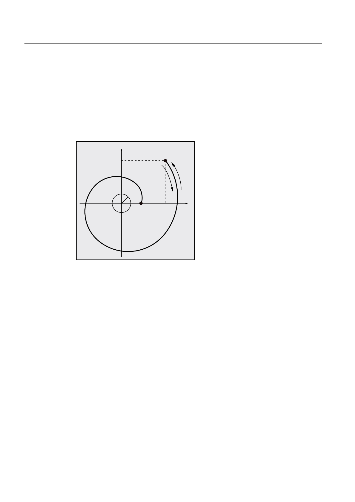
2.1.6 Involute interpolation (G02.2, G03.2)
Overview
The involute of a circle is a curve traced out from the end point on a "piece of string"
unwinding from the curve. The involute interpolation allows trajectories along an involute. It is
executed in the plane in which the base circle is defined. If the starting point and the end
point are not in this plane, then, analogous to the helical interpolation for circles, there is a
superimposition to a curve in space.
Format
<
&5
1HQGSRLQW
; <
1VWDUWSRLQW
; <
1
1
;
An involute can be traversed in space in case of additional specification of paths vertical to
the active plane.
G02.2 X... Y... Z... I... J... K... R
G03.2 X... Y... Z... I... J... K... R
G02.2: Travel on an involute in clockwise direction
G03.2: Travel on an involute in counterclockwise direction
X Y Z: End point in Cartesian coordinates
I J K: Center of the base circle in cartesian coordinates
R: Radius of the base circle
ISO Milling
26 Programming Manual, 06/09, 6FC5398-7BP10-1BA0

Drive commands
2.1 Interpolation commands
Supplementary conditions
Both the starting point and the end point must be outside the area of the base circle of the
involute (circle with radius R around the center point specified by I, J, K). If this condition is
not satisfied, an alarm is generated and the program execution is aborted.
Note
For more information about machine data and supplementary conditions that are relevant to
involute interpolation, please see References: /FB1/, A2 Chapter "Settings for involute
interpolation".
2.1.7 Cylindrical interpolation (G07.1)
Randomly running grooves can be cut on cylindrical workpieces with Function G07.1
(cylindrical interpolation). The path of the grooves is programmed with reference to the
unwinded, plane surface of the cylinder.
The G functions specified below can be used to switch the operation of cylindrical
interpolation on or off.
Table 2- 3 G functions for activating/deactivating the cylindrical interpolation
G function Function G group
G07.1 Operation with cylindrical interpolation 16
Format
G07.1 A (B, C) r ;Activation of operation with cylindrical interpolation
G07.1 A (B, C) 0 ;Deselection of operation with cylindrical interpolation
A, B, C: Address of the rotary axis
r: Radius of the cylinder
No other commands should be present in the block containing G07.1.
The G07.1 command is modal. Once G07.1 is specified, the cylindrical interpolation remains
active till G07.1 A (B, C) is deselected. The cylindrical interpolation is deactivated in closed
position or after NC RESET.
Note
G07.1 is based on the Siemens option TRACYL. Appropriate machine data is to be set for
this.
The corresponding data on this is available in the manual "Extended Functions", Section M1,
TRACYL.
ISO Milling
Programming Manual, 06/09, 6FC5398-7BP10-1BA0
27
Drive commands
2.1 Interpolation commands
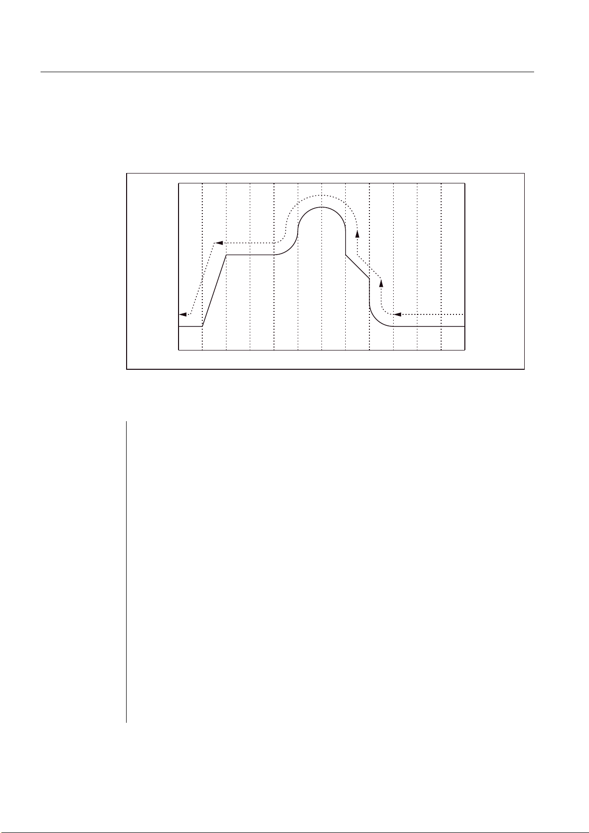
Programming example
At the cylindrical plane (it arises because the circumference of a cylindrical workpiece is
rolled off), in which the Z-axis is accepted as the linear axis and the A-axis as the rotary axis,
the following program is written:
Program
Figure 2-7 G07.1 - Programming example
M19
G40
G00 Z30. A-10.
G07.1 A57.296 ;Operation with cylindrical interpolation ON
;(workpiece radius = 57.926)
G90
G42 G01 A0 F200
G00 X50.
G01 A90. F100
G02 A120. Z60. R30
G01 Z90.
Z120. A150.
Z150.
G03 Z150. A210. R30.
G02 Z120. A240. R30
G01 A300.
Z30. A330.
A360.
G00 X100.
G40 G01 A370.
G07.1 A0 ;Operation with cylindrical interpolation OFF
G00 A0
ISO Milling
28 Programming Manual, 06/09, 6FC5398-7BP10-1BA0

Drive commands
2.1 Interpolation commands
Programming in operation with cylindrical interpolation
Only the following G functions can be used in cylindrical interpolation: G00, G01, G02, G03,
G04, G40, G41, G42, G65, G66, G67, G90, G91 and G07.1. In operation with G00 only
those axes can be used that are not involved at the cylindrical plane.
The following axes cannot be used as a positioning axis or a reciprocating axis:
1. The geometry axis in the peripheral direction of the surface of the cylinder (Y axis)
2. The additional linear axis for groove side offset (Z axis)
Relations between the cylindrical interpolation and operations with reference to the coordinate system
● The functions mentioned below should not be used in operation with cylindrical
interpolation.
– Mirroring
– Scaling (G50, G51)
– Rotation of the coordinate system (G68)
– Setting the basic coordinate system
● The relevant overrides (rapid traverse, JOG, spindle speed) are effective.
● On deselecting this operation with cylindrical interpolation, the interpolation plane that
was selected before the operation with the cylindrical interpolation was called becomes
active again.
● To perform the tool length compensation, the command for the tool length compensation
is to be written before specifying the G07.1 command.
● The work offset (G54 - G59) is also to be written before specifying the G07.1 command.
ISO Milling
Programming Manual, 06/09, 6FC5398-7BP10-1BA0
29
Drive commands
2.2 Reference point approach with G functions
2.2 Reference point approach with G functions
2.2.1 Reference point approach with intermediate point (G28)
Format
G28 X... Y... Z... ;
The commands "G28 X... Y... Z... ;" can be used to traverse the programmed axes to their
reference point. Here, the axes are first traversed to the specified position with rapid
traverse, and from there to the reference point automatically. The axes not programmed in
the block with G28 are not traversed to their reference point.
Reference position
When the machine has been powered up (where incremental position measuring systems
are used), all the axes must approach their reference mark. Only then can traversing
movements be programmed. The reference point can be approached in the NC program with
G28. The reference point coordinates are defined with the machine data 34100
$_MA_REFP_SET_POS[0] up to [3]). A total of four reference positions can be defined.
3URJUDPPLQJH[DPSOH
***;<=
=D[LV
3RVLWLRQLQJ
$
6WDUWSRLQW
=
Figure 2-8 Automatic reference point approach
%
'HOD\RI<D[LV/6
<
5HIHUHQFHSRLQW
DIL[HGSRLQWLQWKHPDFKLQH
'HOD\RI=D[LV/6
5HWXUQWRUHIHUHQFHSRLQW
,QWHUSRODWLRQSRLQWDVLQWHUPHGLDWHSRLQW
GXULQJSRVLWLRQLQJ
<D[LV
ISO Milling
30 Programming Manual, 06/09, 6FC5398-7BP10-1BA0

Drive commands
2.2 Reference point approach with G functions
Return to reference point
Note
The G28 function is implemented with the shell cycle cycle328.spf. A transformation must
not be programmed for an axis which is to approach the reference point with G28 which
must approach the reference mark. The transformation is deactivated in cycle328.spf with
command TRAFOOF.
Automatic reference point approach for rotary axes
Rotary axes can be used for automatic reference point approach exactly as linear axes. The
approach direction of the reference traverse is defined with the machine data 34010
MD_$MA_REFP_CAM_DIR_IS_MINUS.
%% $$
r
5HWXUQWRUHIHUHQFHSRLQW7KHSRVLWLYHWUDYHUVLQJGLUHFWLRQZDVVHOHFWHGDVWKH
GLUHFWLRQRIUHWXUQWRWKHUHIHUHQFHSRLQW
Figure 2-9 Return to reference point - rotary axes
r
r r
Additions to the commands for automatic reference point approach:
Tool radius compensation and defined cycles
G28 should not be used in operation with tool radius compensation (G41, G42) or in a
defined cycle!
WARNING
G28 is used to interrupt the tool radius compensation (G40) with eventual axis traverse
movement to the reference point. Hence, tool radius compensation is to be deactivated
before G28 is issued.
Tool offset in G28
In G28, the interpolation point is approached with the current tool offset. The tool offset is
deselected when the reference point is finally approached.
ISO Milling
Programming Manual, 06/09, 6FC5398-7BP10-1BA0
31

Drive commands
2.2 Reference point approach with G functions
2.2.2 Checking the reference position (G27)
Format
G27 X... Y... Z... ;
This function is used to check whether the axes are on their reference point.
Test procedure
If the check with G27 is successful, the processing is continued with the next part program
block. If one of the axes programmed with G27 is not on the reference point, Alarm 61816
"Axes not on reference point" is triggered and the Automatic mode is interrupted.
Note
Function G27 is implemented with the cycle cycle 328.spf as with G28.
To avoid a positioning error, the function "mirroring" should be deselected before executing
G27.
ISO Milling
32 Programming Manual, 06/09, 6FC5398-7BP10-1BA0

Drive commands
2.2 Reference point approach with G functions
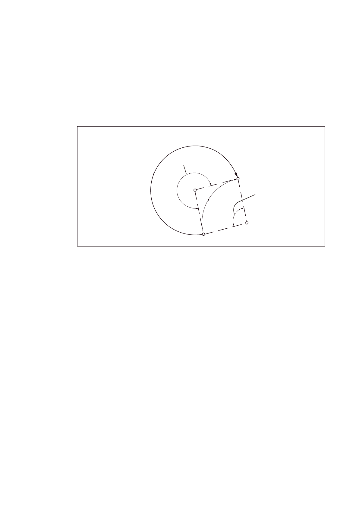
2.2.3 Reference point approach with reference point selection (G30)
Format
G30 Pn X... Y... Z... ;
For the commands "G30 Pn X... Y... Z;" the axes are positioned on the specified
intermediate point in the continuous-path mode, and finally traversed to the reference point
selected with P2 - P4. With "G30 P3 X30. Y50.;", The X- and Y-axes return to the third
reference point. The second reference point is selected on omitting "P". Axes that are not
programmed in a G30 block are also not traversed.
Reference point positions
The positions of all the reference points are always determined in relation to the first
reference point. The distance of the first reference point from all subsequent reference points
is set in the following machine data:
Table 2- 4 Reference points
Element MD
2. Reference point $_MA_REFP_SET_POS[1]
3. Reference point $_MA_REFP_SET_POS[2]
4. Reference point $_MA_REFP_SET_POS[3]
Note
Further details of the points that were considered in the programming of G30 are available in
the Chapter "Reference point approach with intermediate point (G28)". Function G30 is
implemented with the cycle 328.spf as with G28.
ISO Milling
Programming Manual, 06/09, 6FC5398-7BP10-1BA0
33

Drive commands
2.2 Reference point approach with G functions
ISO Milling
34 Programming Manual, 06/09, 6FC5398-7BP10-1BA0

Motion commands
3.1 The coordinate system
The position of a tool is defined uniquely by its coordinates in the coordinate system. These
coordinates are defined through axis positions. If, for instance, the three involved Axes are
denoted by X, Y and Z, the coordinates are specified as follows:
X... Y... Z...
3
=
<
;
Figure 3-1 Tool positions specified with X... Y... Z...
The following coordinate systems are used to specify the coordinates:
1. Machine coordinate systems (G53)
2. Workpiece coordinate system (G92)
3. Local coordinate system (G52)
ISO Milling
Programming Manual, 06/09, 6FC5398-7BP10-1BA0
35

Motion commands
3.1 The coordinate system
3.1.1 Machine coordinate systems (G53)
Defining machine coordinate system
The machine zero defines the machine coordinate system MCS. All other reference points
refer to the machine zero.
The machine zero is a fixed point on the machine tool which can be referenced by all
(derived) measuring systems.
This is not necessary if an absolute measuring system is used.
Format
(G90) G53 X... Y... Z... ;
X, Y, Z: absolute dimension word
Selection of machine coordinate system (G53)
G53 suppresses the programmable and adjustable work offset . Traversing in the machine
coordinate system on the basis of G53 are always programmed if the tool is to traverse to a
machine-specific position.
Compensation deselection
If MD10760 $MN_G53_TOOLCORR = 0, then the active tool length and tool radius
compensation remains active in a block with G53
If MD10760 $MN_G53_TOOLCORR = 1, then the active tool length and tool radius
compensations in a block are suppressed with G53.
Reference
MD24004 $MC_CHBFRAME_POWERON_MASK, Bit 0 is used to define whether channelspecific basic frames during Power On are to be reset.
Displacements and rotations are set to 0, scalings to 1.
Mirroring is switched off.
Value = 0: Basic frame is retained at Power ON
Value = 1: Basic frame is reset at Power On.
ISO Milling
36 Programming Manual, 06/09, 6FC5398-7BP10-1BA0

Motion commands
3.1 The coordinate system
0DFKLQHFRRUGLQDWHV\VWHP
0DFKLQH]HUR
˟
˞
5HIHUHQFHSRVLWLRQ
Figure 3-2 Reference
3.1.2 Workpiece coordinate system (G92)
Before machining, you must create a coordinate system for the workpiece, the so-called
work piece coordinate system. This section describes different methods of setting, selecting
and changing a workpiece coordinate system.
Setting a tool coordinate system
The following two methods can be used to set a tool coordinate system:
1. With G92 in the part program
2. manually through the HMI operator panel
Format
(G90) G92 X... Y... Z... ;
The base point traverses to the specified position on outputting an absolute command. The
difference between tool tips and the base point is compensated through the tool length
compensation; this way the tool tip can traverse to the target position in any case.
ISO Milling
Programming Manual, 06/09, 6FC5398-7BP10-1BA0
37

Motion commands
3.1 The coordinate system
3.1.3 Resetting the tool coordinate system (G92.1)
With G92.1 X.. (G Code System A with G50.3 P0) one can reset a shifted coordinate system
before the shift. The tool coordinate system is reset to the coordinate system that is defined
by the active adjustable work offsets (G54-G59). The tool coordinate system is set to the
reference position if no adjustable work offset is active. G92.1 resets shifts carried out
through G92 or G52. However, only the axes that are programmed, are reset.
Example 1:
N10 G0 X100 Y100 ;Display: WCS: X100 Y100 MCS: X100 Y100
N20 G92 X10 Y10 ;Display: WCS: X10 Y10 MCS: X100 Y100
N30 G0 X50 Y50 ;Display: WCS: X50 Y50 MCS: X140 Y140
N40 G92.1 X0 Y0 ;Display: WCS: X140 Y140 MCS: X140 Y140
Example 2:
N10 G10 L2 P1 X10 Y10
N20 G0 X100 Y100 ;Display: WCS: X100 Y100 MCS: X100 Y100
N30 G54 X100 Y100 ;Display: WCS: X100 Y100 MCS: X110 Y110
N40 G92 X50 Y50 ;Display: WCS: X50 Y50 MCS: X110 Y110
N50 G0 X100 Y100 ;Display: WCS: X100 Y100 MCS: X160 Y160
N60 G92.1 X0 Y0 ;Display: WCS: X150 Y150 MCS: X160 Y160
3.1.4 Selection of a workpiece coordinate system
As mentioned above, the user can select one of the already set workpiece coordinate
systems.
1. G92
Absolute commands function in connection with a workpiece coordinate system only if a
workpiece coordinate system was selected earlier.
2. Selection of a workpiece coordinate system from a selection of specified workpiece
coordinate systems via the HMI operator panel
A workpiece coordinate system can be selected by specifying a G function in the area
G54 to G59 and G54 P{1...100}.
Workpiece coordinate systems are setup after the reference point approach after Power
On. The closed position of the coordinate system is G54.
3.1.5 Writing work offset/tool offsets (G10)
The workpiece coordinate systems defined through G54 to G59 or G54 P{1 ... 93} can be
changed with the following two processes.
1. Data inputting at HMI operator panel
2. with the program commands G10 or G92 (setting actual value, spindle speed limitation)
ISO Milling
38 Programming Manual, 06/09, 6FC5398-7BP10-1BA0

Motion commands
3.1 The coordinate system
Format
Modified by G10:
G10 L2 Pp X... Y... Z... ;
p=0: External workpiece work offset
p=1 to 6: The value of the workpiece work offset corresponds to the workpiece
coordinate system G54 to G59 (1 = G54 to 6 = G59)
X, Y, Z: Workpiece work offset for each axis during an absolute command (G90).
Value that must be added during an incremental command (G91) for each
axis to the specified workpiece work offset.
G10 L20 Pp X... Y... Z... ;
p=1 to 93: The value of the workpiece work offset corresponds to the workpiece
coordinate system G54 P1 ... P93. The number of work offsets (1 to 93)
can be set through MD18601 $MN_MM_NUM_GLOBAL_USER_FRAMES
or MD28080 $MC_MM_NUM_USER_FRAMES.
X, Y, Z: Workpiece work offset for each axis during an absolute command (G90).
Value that must be added during an incremental command (G91) for each
axis to the specified workpiece work offset.
Explanations
Modified by G92:
G92 X... Y... Z... ;
Modified by G10:
G10 can be used to change each workpiece coordinate system individually. If the work offset
with G10 is to be written only when the G10 block is executed on the machine (main run
block), then MD20734 $MC_EXTERN_FUNCTION_MASK, Bit 13 must be set. An internal
STPPRE is executed in that case with G10. The machine data bits affect all G10 commands
in the ISO Dialect T and ISO Dialect M.
Modified by G92:
By specifying G92 X... Y... Z..., a workpiece coordinate system that was selected earlier with
a G command G54 to G59 or G54 P{1 ...93}, can be shifted and thus a new workpiece
coordinate system can be set. If X, Y and Z are programmed incrementally, the workpiece
coordinate system is defined in such a way that the current tool position matches the total of
the specified incremental value and the coordinates of the previous tool position (shift of
coordinate system). Finally, the value of the coordinate system shift is added to each
individual value of the workpiece work offset. To put it another way: All workpiece coordinate
systems are shifted systematically by the same value.
ISO Milling
Programming Manual, 06/09, 6FC5398-7BP10-1BA0
39

Motion commands
3.1 The coordinate system
Example
The tool in operation with G54 is positioned at (190, 150), and the workpiece coordinate
system 1 (X' - Y') is created each time in G92X90Y90 with a shift of Vector A.
<<ಫ
*:RUNSLHFHFRRUGLQDWHV\VWHP
Figure 3-3 Example of setting coordinates
3.1.6 Local coordinate system (G52)
For programming simplification, a type of workpiece coordinate system can be setup to
create a program in the workpiece coordinate system. This part coordination system is also
called local coordinate system.
Format
G52 X... Y... Z... ; Setting the local coordinate system
7RROSRVLWLRQ
;ಫ
;
$
G52 X0 Y0 Z0 ; Deselection of the local coordinate system
X, Y, Z: Origin of the local coordinate system
Explanations
G52 can be used to program work offsets for all path and positioning axes in the direction of
the specified axis. This way one can work with changing zero points, e.g. during repetitive
machining operations at different workpiece positions.
G52 X... Y... Z... is a work offset around the offset values programmed in the relevant
specified axis directions. The last specified adjustable work offset (G54 to G59, G54 P1 P93) serves as reference.
ISO Milling
40 Programming Manual, 06/09, 6FC5398-7BP10-1BA0
Motion commands
3.1 The coordinate system
*:RUNSLHFHFRRUGLQDWHV\VWHP
ORFDOFRRUGLQDWHV\VWHP
*
*
2ULJLQRIPDFKLQHFRRUGLQDWHV\VWHP
*
*
0DFKLQHFRRUGLQDWHV\VWHP
ORFDOFRRUGLQDWHV\VWHP
*:RUNSLHFHFRRUGLQDWHV\VWHP
5HIHUHQFHSRLQW
Figure 3-4 Setting the local coordinate system
3.1.7 Selection of the plane (G17, G18, G19)
The selection of the plane in which the circular interpolation, tool radius compensation and
rotation of the coordinate system took place is done by specifying the following G functions.
Table 3- 1 G functions for selecting the plane
G function Function G group
G17 X-Y plane 02
G18 Z-X plane 02
G19 Y-Z plane 02
The plane is defined as described below (with the help of the example of Plane X-Y):
The horizontal axis in the first quadrant is the Axis +X, and the vertical axis in the same
quadrant is Y-.
<D[LV
Figure 3-5 Selection of plane
ISO Milling
Programming Manual, 06/09, 6FC5398-7BP10-1BA0
;D[LV
41

Motion commands
3.1 The coordinate system
● The Plane X-Y (G17) is selected automatically after activating the control system.
● The command for moving an individual axis can be specified independently of the plane
selection by G17, G18 or G19. Thus for instance, the Z axis can be shifted by specifying
"G17 Z ....;".
● The plane in which the tool radius compensation is executed with G41 or G42 is defined
by specifying G17, G18 or G19.
3.1.8 Parallel axes (G17, G18, G19)
An axis located parallel to one of the three main axes of the coordinate system can be
activated by using the function G17 (G18, G19) <Axis name>.
The three main axes are, e.g., X, Y and Z.
Example
G17 U0 Y0
The parallel axis U is activated when the X axis in the G17 plane is replaced.
Explanations
● An associated parallel axis can be defined for each geometry axis with machine data
$MC_EXTERN_PARALLEL_GEOAX[ ].
● Only geometry axes from a plane defined with (G17, G18, G19) can be replaced.
● On replacing the axes, normally all shifts (frames) - with the exception of the handwheel
and external shifts, the working area limitation and the protection areas - are deleted. The
following machine data is to be set to prevent the values from being deleted:
Shifts (frames)
$MN_FRAME_GEOAX_CHANGE_MODE
Protection areas
$MC_PROTAREA_GEOAX_CHANGE_MODE
Working area limitation
$MN_WALIM_GEOAX_CHANGE_MODE
● Details are available in the machine data description.
● Alarm 12726 "Impermissible plane selection with parallel axes" is output if a main axis is
programmed along with the associated parallel axis with a command for selecting the
plane.
ISO Milling
42 Programming Manual, 06/09, 6FC5398-7BP10-1BA0

Motion commands
3.1 The coordinate system
3.1.9 Rotation of the coordinate system (G68, G69)
Properties of G68 and G69
A coordinate system can be rotated with the following G functions.
Table 3- 2 G functions for rotating a coordinate system
G function Function G group
G68 Rotation of the coordinate system 16
G69 Deselection of Rotation of the coordinate system 16
G68 and G69 are modal G functions of the G group 16. G69 is set automatically on
activating the control system and resetting the NC.
The blocks containing G68 and G69 should not contain any other G functions.
The rotation of the coordinate system is called with G68 and deselected with G69.
Format
G68 X_ Y_ R_ ;
X_, Y_ :
Absolute coordinate values of the rotation center. The actual position is accepted as the
rotation center if these are omitted.
R_ :
Angle of rotation as a function of G90/G91 absolute or incremental. If R is not specified, the
value of the channel-specific setting from the setting data 42150
$SC_DEFAULT_ROT_FACTOR_R is used as angle of rotation.
ISO Milling
Programming Manual, 06/09, 6FC5398-7BP10-1BA0
43
Motion commands
3.1 The coordinate system
● By specifying G17 (or G18, G19) G68 X... Y... R... ; " the commands specified in the
following blocks are rotated by the angle specified with R around the point (X, Y). The
angle of rotation can be specified in units of 0.001 degree.
;<&HQWHURIURWDWLRQ
5$QJOHRIURWDWLRQಯಯPHDQVURWDWLRQLQ
FRXQWHUFORFNZLVHGLUHFWLRQLVWREH
VSHFLILHGDVDEVROXWHYDOXH
5
;<
Figure 3-6 Rotation of a coordinate system
● The deselection of the coordinate system rotation takes place through G69.
● G68 is executed in the plane that was selected through G68. The 4th and 5th axes must
be linear axes.
G17: X-Y plane
G18: Z-X plane
G19: Y-Z plane
Additions to the commands for rotating the coordinate systems
● To rotate a coordinate system, MD28081 $MC_MM_NUM_BASE_FRAMES must be set
to a value of >= 3.
● If "X" and "Y" are omitted, the current position is used as the rotation center for the
coordinate rotation.
● The positional data for the rotation of a coordinate system are specified in the rotated
coordinate system.
● If you program a change of plane (G17 to G19) after a rotation, the angles of rotation
programmed for the axes are retained and continue to apply in the new working plane. It
is therefore advisable to deactivate the rotation before a change of plane.
ISO Milling
44 Programming Manual, 06/09, 6FC5398-7BP10-1BA0

Motion commands
3.1 The coordinate system
3.1.10 3D rotation G68/G69
The G code G68 is extended for 3D rotation.
Format
G68 X.. Y.. Z.. I.. J.. K.. R..
X.. Y.. Z..: Coordinates of the pivot point related to the current workpiece zero. If no
coordinate is programmed, the pivot point lies in the workpiece zero. The
value is always interpreted as absolute. The coordinates of the pivot point
act as a work offset. G90/G91 in the block does not affect the G68
command.
I.. J.. K..: Vector in pivot point. The coordinate system is rotated around this vector at
angle R.
R..: Angle of rotation. The angle of rotation is always absolute. If no angle is
programmed, the angle from the setting data 42150
$SA_DEFAULT_ROT_FACTOR_R is active. G68 must be alone in the block.
The 2D or 3D rotation differentiation takes place only through the programming of the vector
I, J, K. If there is no vector in the block, G68 2DRot is selected. If there is a vector in the
block, G68 3DRot is selected.
If a vector is programmed with the length 0 (I0, Y0, K0), the Alarm 12560 "Programmed
value outside the permissible limits" is triggered.
Two rotations can be switched one after the other with G68. If so far no G68 is active in a
block containing G68, then the rotation is written to the channel-specific basic frame 2. If
G68 is already active, the rotation is written to the channel-specific basic frame 3. Thus, both
rotations follow one another.
The 3D rotation is ended with G69. If two rotations are active, both are deselected with G69.
G69 must not be alone in the block.
ISO Milling
Programming Manual, 06/09, 6FC5398-7BP10-1BA0
45

Motion commands
3.2 Defining the input modes of the coordinate values
3.2 Defining the input modes of the coordinate values
3.2.1 Absolute/incremental dimensioning (G90, G91)
Whether the dimensions after an axis address should be absolute or relative (incremental) is
specified with these G commands.
Properties of G90, G91
Table 3- 3 G commands for defining the absolute/incremental dimensioning
G command Function G group
G90 Absolute dimensioning 03
G91 Incremental dimensioning 03
● G90 and G91 are modal G functions of the G group 03. If G90 and G91 are programmed
in the same block, the last G function in the block is effective.
Format
● The closed position of G90 or G91 is set in machine data MD20154
$MC_EXTERN_GCODE_RESET_VALUES[2].
● The programmed values are interpreted as absolute axis positions for all axis positions
programmed according to G90, e.g. X, Y, Z.
● The programmed values are interpreted as incremental axis positions for all axis
positions programmed according to G91, e.g. X, Y, Z.
$EVROXWHGLPHQVLRQ*
<
3
3
3
;
,QFUHPHQWDOGLPHQVLRQ*
<
3
3
3
;
Figure 3-7 Absolute and incremental dimensioning (G90, G91)
ISO Milling
46 Programming Manual, 06/09, 6FC5398-7BP10-1BA0

Motion commands
3.2 Defining the input modes of the coordinate values
3.2.2 Inch/metric input (G20, G21)
Workpiece-related axes can be programmed in metric or inch dimensions alternately,
depending on the dimensioning in the production drawing. The input unit is selected with the
following G functions.
Table 3- 4 G command for selecting the unit of measurement
G command Function G group
G20 Input in "inch" 06
G21 Input in "mm" 06
Format
G20 and G21 are always to be programmed at the start of the block and should not exist
along with other commands in a block. The following values are processed in the selected
unit of measurement while executing the G function for selecting the unit of measurement:
All the following programs, offset values, certain parameters as well as certain manual
operation and readout data.
*
*
Figure 3-8 Programming example
'HILQLQJWKHLQSXWIRUPDWLQFK
Additions to the commands for defining the unit of measurement
● The closed position is defined via the machine data MD20154
$MC_EXTERN_GCODE_RESET_VALUES[5].
● During changeover, the values of the work offsets are changed completely.
● If the unit of measurement is changed over during program execution, the following must
be executed in advance:
While using a workpiece coordinate system (G54 to G59), this is to be traced back to the
basic coordinate system.
All tool offsets are to be deactivated (G41 to G48).
● The following is to be done after switching the measuring system from G20 to G21:
G92 must be executed before specifying the traversing commands for the axes (to setup
the coordinate system).
● G20 and G21 are not used to switch the hand wheel- and incremental weighting. This
takes place through the PLC program. The machine data responsible for this is called
$MA_JOG_INCR_WEIGHT.
ISO Milling
Programming Manual, 06/09, 6FC5398-7BP10-1BA0
47

Motion commands
3.2 Defining the input modes of the coordinate values
3.2.3 Scaling (G50, G51)
Properties of G50, G51
The form defined by a part program can be enlarged or reduced according to the required
scale. The desired scaling can be selected and deselected via the following functions.
Table 3- 5 G functions for selecting the scale
G command Function G group
G50 Scaling OFF 11
G51 Scaling ON 11
The selection for scaling and mirroring takes place with G51. A distinction is made between
two options in scaling:
● Axial scaling with the parameters I, J, K
If I, J, K is not programmed in the G51 block, the relevant default value from the setting
data 43120 $A_DEFAULT_SCALE_FACTOR_AXIS is effective.
Negative axial scaling factors lead additionally to mirroring.
● Scaling in all axes with the scaling factor P
If P is not written in the block G51, the default value from the setting data is effective.
Negative P values are not possible.
Format
There are two different types of scaling.
Scaling along all axes with the same scaling factor
G51 X... Y... Z... P... ; Start scaling
G50; Deselection of scaling
X, Y, Z: Center coordinate value for the scaling (absolute command)
P: Scaling factor
ISO Milling
48 Programming Manual, 06/09, 6FC5398-7BP10-1BA0

Motion commands
3.2 Defining the input modes of the coordinate values
Scaling along each individual axis with different scaling factors
G51 X... Y... Z... I... J... K... ; Start scaling
G50; Deselection of scaling
X, Y, Z: Reference point of scaling (absolute command)
I, J, K: Scaling factor for the X-, Y- and Z-axis
The type of the scaling factor depends on MD22914 $MC_AXES_SCALE_ENABLE.
$MC_AXES_SCALE_ENABLE = 0:
The scaling factor is specified with "P". If "I,J,K" is programmed in this setting, the setting
data 42140 $SC_DEFAULT_SCALE_FACTOR_P is used for the scaling factor.
$MC_AXES_SCALE_ENABLE = 1:
The scaling factor is specified with "I,J,K". If only "P" is programmed in this MD setting, the
setting data 43120 $SA_DEFAULT_SCALE_FACTOR_AXIS is used for the scaling factors.
Weighting of scaling factors
The scaling factors are multiplied either with 0.001 or 0.00001. The factors are selected with
MD22910 $MC_WEIGHTING_FACTOR_FOR_SCALE=0, scaling factor 0.001,
$MC_WEIGHTING_FACTOR_FOR_SCALE=1, scaling factor 0.00001.
The workpiece zero is always the reference point for the scaling. A reference point cannot be
programmed.
Programmable mirroring (negative scaling)
A mirror image can be created with a negative value of the axial scaling factor.
To do this, MD22914 $MC_AXES_SCALE_ENABLE = 1 must be active. If I, J or. K is
omitted from the blocks with G51, the values preset in the setting data 43120
$SA_DEFAULT_SCALE_FACTOR_AXIS are activated.
Example
_N_0512_MPF ;(Part program)
N01 G291
N10 G17 G90 G00 X0 Y0 ;Start position for the approach motion
N30 G90 G01 G94 F6000
N32 M98 P0513 ;1) Contour programmed as in the subroutine
N34 G51 X0. Y0. I-1000 J1000 ;2) Contour, mirrored on X
N36 M98 P0513
N38 G51 X0. Y0. I-1000 J-1000 ;3) Contour, mirrored on X and Y
N40 M98 P0513
N42 G51 X0. Y0. I1000 J-1000 ;4) Contour, mirrored on Y
N44 M98 P0513
N46 G50 ;Deselection of scaling and mirroring
N50 G00 X0 Y0
N60 M30
ISO Milling
Programming Manual, 06/09, 6FC5398-7BP10-1BA0
49
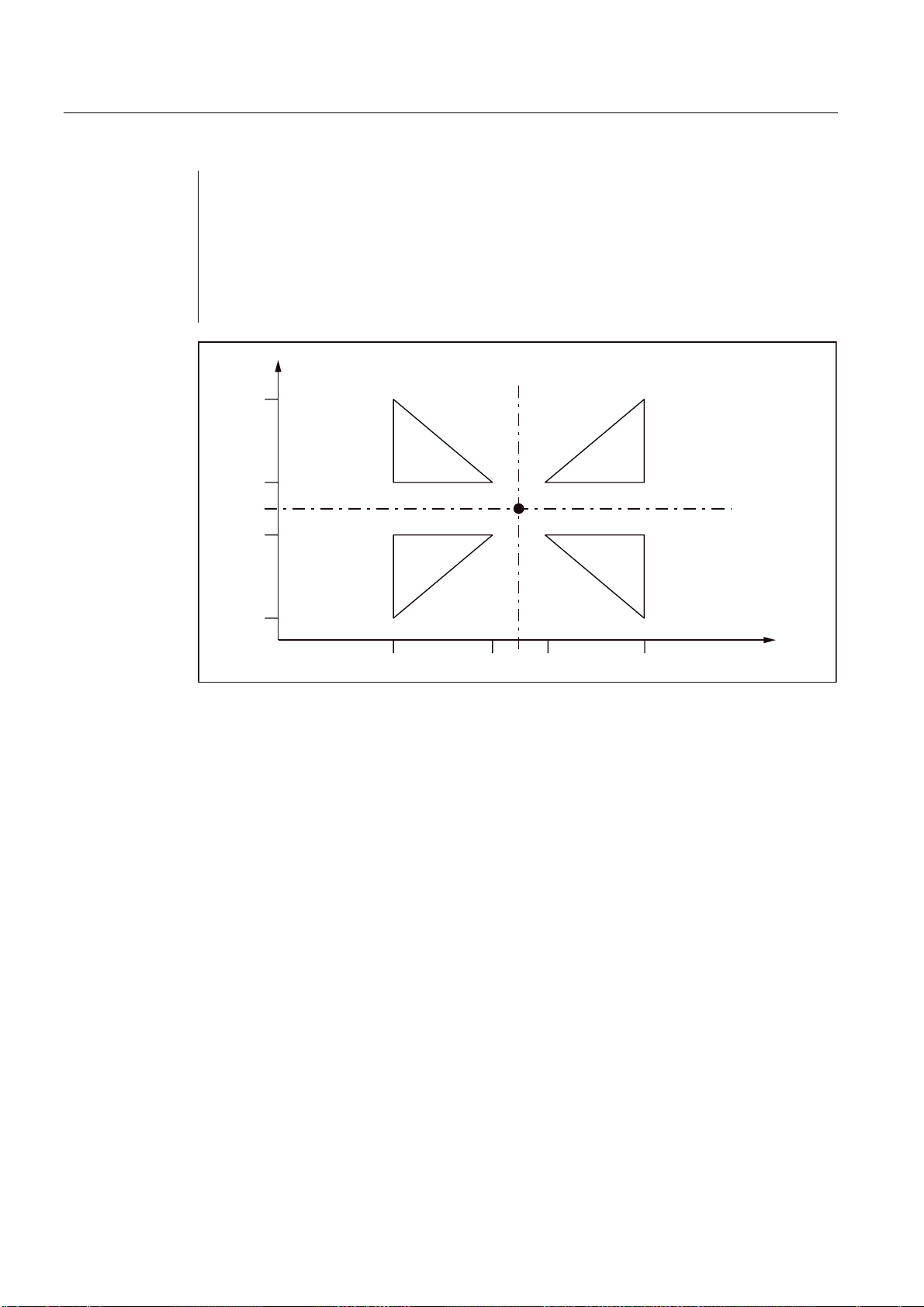
Motion commands
3.2 Defining the input modes of the coordinate values
_N_0513_MPF ;(Subroutine of 00512)
N01 G291
N10 G90 X10. Y10.
N20 X50
N30 Y50
N40 X10. Y10.
N50 M99
6WDUWSRLQW
Figure 3-9 Scaling for each axis and programmable mirroring
Tool offset
This scaling is not valid for cutter radius compensations, tool length compensations and tool
offset values.
Commands for reference point approach and for changing the coordinate system
The G27, G28 and G30 functions as well as commands related to the coordinate system
(G52 to G59, G92), should not be used when scaling is active.
ISO Milling
50 Programming Manual, 06/09, 6FC5398-7BP10-1BA0

Motion commands
3.2 Defining the input modes of the coordinate values
3.2.4 Programmable mirroring (G50.1, G51.1)
G51.1 can be used to mirror workpiece shapes on coordinate axes. All programmed
traversing movements are then executed as mirrored.
<
3URJUDPPHGFRQWRXURULJLQDO
6\PPHWULFDOPDSSLQJZLWKUHIHUHQFHWRWKHOLQHWKDWUXQVSDUDOOHOWR<DQGLQWHUVHFWV;DW
6\PPHWULFDOPDSSLQJZLWKUHIHUHQFHWRWKH3RLQW
6\PPHWULFDOPDSSLQJZLWKUHIHUHQFHWRWKHOLQHWKDWUXQVSDUDOOHOWR;DQGLQWHUVHFWV<DW
$[LVRIV\PPHWU\;
$[LVRIV\PPHWU\
;
<
Figure 3-10 Programmable Mirroring
Format
X, Y, Z: Positions and mirroring axis
G51.1: Command for activating the mirroring
Mirroring takes place on a mirroring axis which is parallel to X, Y or Z and whose position is
programmed with X, Y or Z. G51.1 X0 is used to mirror on the X axis, G51.1 X10 is used to
mirror on a mirroring axis that runs 10 mm parallel to the X axis.
ISO Milling
Programming Manual, 06/09, 6FC5398-7BP10-1BA0
51

Motion commands
3.2 Defining the input modes of the coordinate values
Example
N1000 G51.1 X... Y... Z... ; Activate mirroring
... ;
... ;
... ;
... ;
G50.1 X... Y... Z.. ; Deselection of programmable mirroring
All the axis positions mirrored in the following
;
blocks are mirrored at the mirroring axis programmed
;
in N1000
Required machine data
G51.1 uses the channel-specific basic frame [1]. Hence, MD28081
$MC_MM_NUM_BASE_FRAMES > = 2 is to be set.
Mirroring with reference to a single axis in a specified plane
The following commands can change if the mirroring is used on one of the axes in the
specified plane as described below:
Table 3- 6 Individual axes in specified plane
Command Explanation
Circular interpolation G02 and G03 are exchanged mutually
Cutter radius compensation G41 and G42 are exchanged with each other
Coordinate rotation The "clockwise" (CW) and "counter-clockwise" (CCW) directions of
rotation are exchanged mutually.
Commands for reference point approach and for changing the coordinate system
The G27, G28 and G30 functions as well as commands related to the coordinate system
(G52 to G59, G92, etc), should not be used when mirroring is active.
ISO Milling
52 Programming Manual, 06/09, 6FC5398-7BP10-1BA0

Motion commands
3.3 Time-controlled commands
3.3 Time-controlled commands
3.3.1 Dwell time (G04)
One can use G04 to interrupt workpiece machining between two NC blocks for a
programmed time/number of spindle revolutions, e.g. for backing off.
One can set with MD20734 $MC_EXTERN_FUNCTION_MASK, whether the dwell time for
Bit 2 is to be interpreted as time (s or ms) or alternatively as spindle revolutions. If
$MC_EXTERN_FUNCTION_MASK, Bit 2=1 is set, the dwell time is interpreted in seconds if
G94 is active; it is specified in spindle revolutions (R) if G95 is selected.
Format
G04 X_; or G04 P_;
X_: Time display (commas possible)
P_: Time display (commas not possible)
● The dwell time (G04 ..) must be programmed alone in a block.
If the values of X and U are programmed in the standard notation (without decimal point),
they are converted to internal units, depending on IS B, IS C (for input resolution, see
Chapter "Decimal point programming"). P is always interpreted in internal units.
N5 G95 G04 X1000
Standard notation: 1000*0.001 = 1 Spindle revolution
Calculator notation: 1000 spindle revolutions
ISO Milling
Programming Manual, 06/09, 6FC5398-7BP10-1BA0
53

Motion commands
3.4 Tool offset functions
3.4 Tool offset functions
3.4.1 Tool offset data memory
The Siemens tool data memory must be used, as programs in the Siemens Mode and in the
ISO Direct Mode must run alternately on the control system. Hence, length, geometry and
wear exists in each tool offset data memory. In the Siemens mode, the offset data memory is
addressed with "T" (Tool No.) and "D" (cutting edge no.). abbreviated as T/D No.
In programs that are written in ISO dialect, the tool offset no. is addressed with "D" (radius)
or H (length), denoted hereafter as D/H No.
For unique assignment between D and H numbers or the T/D number, one must add the
$TC_DPH[t,d] element to the tool data offset memory. The D/H number is input in ISO
dialect in this element.
Table 3- 7 Example: Set tool offset data
T D/cutting edge ISO_H
$TC_DPH
1 1 10
1 2 11
1 3 12
2 1 13
2 2 14
2 3 15
For an assignment of tool length compensations of the geometry axes that is independent of
the plane selection, the setting data $SC_TOOL_LENGTH_CONST must contain the value
"17". Length 1 is always assigned to the Z axis in this case.
3.4.2 Tool length compensation (G43, G44, G49)
In tool length compensation, the amount of the specified values in the program stored in the
tool offset data memory is added to the Z axis or subtracted from it to undertake a offset of
the programmed paths according to the length of the cutting tool.
Commands
While executing the tool length compensation, the addition or subtraction of the tool offset
data is determined through the used G function and the direction of offset is determined with
the H functions.
Radius Length
ISO Milling
54 Programming Manual, 06/09, 6FC5398-7BP10-1BA0
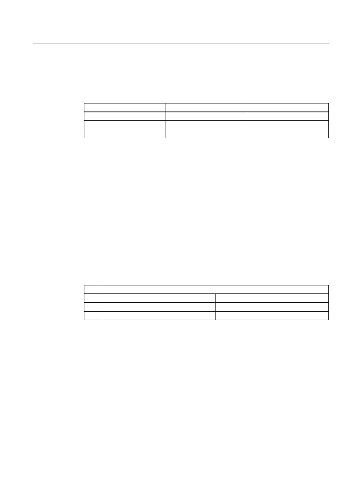
Motion commands
3.4 Tool offset functions
G functions used for the tool length compensation
The tool length compensation is called with the following G functions.
Table 3- 8 G functions used for the tool length compensation
G function Function G group
G43 Addition 08
G44 Subtraction 08
G49 Deselection 08
● G43 and G44 are modal and remain active till they are deselected through G49. The tool
length compensation is deselected with G49. H00 can also be used to deselect the tool
length compensation.
● By specifying "G43 (or G44) Z... H... ; " the tool offset amount specified with the H
function is added to or subtracted from the specified position of the Z axis, and the Z axis
then traverses to the corrected target position, i.e., the target position of the Z axis
specified in the program is shifted by the magnitude of the tool offset.
● By specifying "(G01) Z... ; G43 (or G44) H... ; " the Z axis traverses the path that
corresponds to the tool offset amount specified via the H function.
● By specifying "G43 (or G44) Z...H...H... ; " the Z axis traverses the path that corresponds
to the difference between the previous tool offset amount and the new tool offset amount.
H function for specification of the tool offset direction
The direction of tool offset is determined by the sign of the tool length compensation that is
activated by the H function, and the programmed G function.
Table 3- 9 Signs are present before the amount of tool offset and direction of tool offset
Signs of tool offset amount (H function)
positive negative
G43 Tool offset in positive direction Tool offset in negative direction
G44 Tool offset in negative direction Tool offset in positive direction
ISO Milling
Programming Manual, 06/09, 6FC5398-7BP10-1BA0
55

Motion commands
3.4 Tool offset functions
3URJUDPPLQJH[DPSOH
+2IIVHW
+2IIVHW
3RVLWLRQGDWDLQGLFDWRU
LQFOXGLQJRIIVHW
=D[LVRQO\
1*=
1**;<
1*=+
1*,=)O
1*=+
1*;<
1*=+,
1*=)
1*=+
Settings
3URJUDPPHGSRVLWLRQ
7RROSRVLWLRQ
3URJUDPPHGSRVLWLRQ
7RROSRVLWLRQ
Figure 3-11 Tool position offset
● The machine data $MC_TOOL_CORR_MOVE_MODE determines whether the tool length
compensation is to be undertaken with the selection of the tool offset or only during the
programming of an axis motion.
$MC_CUTTING_EDGE_DEFAULT = 0 defines that initially no tool length compensation is
active during a tool change.
$MC_AUXFU_T_SYNC_TYPE defines whether the output of the T function to the PLC
takes place during or after the traversing movement.
$MC_RESET_MODE_MASK, Bit 6, can be used to define that the currently active tool
length compensation will remain active even after a RESET.
● The cutter radius compensation can also be called for an operation with tool length
compensation.
ISO Milling
56 Programming Manual, 06/09, 6FC5398-7BP10-1BA0

Motion commands
3.4 Tool offset functions
Tool length compensation in several axes
Tool length compensation can also be activated for several axes. A display of the resulting
tool length compensation is not possible any more in that case.
3.4.3 Cutter radius compensation (G40, G41, G42)
In cutter radius compensation, the programmed tool paths are shifted automatically by the
radius of the cutting tool used. The path to be corrected (radius of the cutting tool) can be
stored in the tool offset data memory using the NC operator panel. The tool offsets can also
be overwritten with the G10 command in the part program; G10 cannot be used to create
new tools.
The tool offset data in the program is called by specifying the number of the tool offset data
memory with a D function.
Commands
The cutter radius compensation is called with the following G functions.
Table 3- 10 G functions for calling the cutter radius compensation
G function Function G group
G40 Deselection of the tool radius
compensation
G41 Tool radius compensation (tool works in
machining direction to the left of the
contour)
G42 Tool radius compensation (tool works in
machining direction to the right of the
contour)
07
07
07
The tool radius compensation is called by executing G41 or G42 and deselected through
G40. The offset direction is determined through the specified G function (G41, G42) and the
offset amount is determined through the D function.
*FRUUHFWLRQWRWKHOHIW
7RRO
3URJUDPPHGSDWK
'
'
Figure 3-12 Cutter radius compensation
ISO Milling
Programming Manual, 06/09, 6FC5398-7BP10-1BA0
*FRUUHFWLRQWRWKHULJKW
57

Motion commands
3.4 Tool offset functions
● A negative offset value of the tool radius is equivalent to a change of compensation side
(G41, G42). The D function must either be programmed in the same block as G41 or G42
or in a previous block. D00 means tool radius = "0".
● The selection of the plane in which the tool radius is active is done with G17, G18 or G19.
The G function used to select the plane is to be programmed in the same block as G41 or
G42 or in the block before G41 or G42.
Table 3- 11 G functions for selecting the plane
G function Function G group
G17 Selection of plane X-Y 02
G18 Selection of plane Z-X 02
G19 Selection of plane Y-Z 02
● The selected plane should not be changed if the tool offset is selected, otherwise there is
an error message.
Activation/deactivation of tool radius compensation
A drive command must be programmed with G0 or G1 if an NC block contains G40, G41 or
G42. At least one axis of the selected working plane must be specified in this drive
command.
Note
Compensation mode
Compensation mode may only be interrupted by a certain number of consecutive blocks or
M functions which do not contain drive commands or positional data in the compensation
plane: Standard 3.
Note
Machine manufacturer
The number of successive interruptions blocks or M functions can be set via the machine
data 20250 CUTCOM_MAXNUM_DUMMY_BLOCKS (refer to machine manufacturer).
Note
A block with path zero is also taken as interruption!
ISO Milling
58 Programming Manual, 06/09, 6FC5398-7BP10-1BA0

Motion commands
3.4 Tool offset functions
Changeover between G41 and G42 in operation with cutter radius compensation
The offset direction (left or right) can be changed over directly without having to leave the
compensation mode.
The new offset direction is approached with the next block, through an axis motion.
3URJUDPPLQJH[DPSOH
1**)
1**'
1*;<)
1**;<
1;
6HWIRUVZLWFKLQJWKHRIIVHWGLUHFWLRQ
*
1
D**
*
E**
1
11
1
*
*
1
1RWH,IWKHFRQWHQWRI%ORFN1LVUHSURGXFHGLQWZREORFNVDVVSHFLILHGEHORZ
*RU*
;<
WKHRIIVHWGLUHFWLRQLVDOVRVZLWFKHGRYHULQWKHVDPHZD\
Figure 3-13 Changeover of the tool offset direction at block start and end of block
Deselection of the tool offset
There are two methods of deselecting the tool offset, which can be set through the setting
data 42494 $SC_CUTCOM_ACT_DEACT_CTRL.
1. Method A:
If G40 is programmed in a block without axis motion, the tool radius compensation is
deselected only with the next block through an axis motion.
ISO Milling
Programming Manual, 06/09, 6FC5398-7BP10-1BA0
59

Motion commands
3.4 Tool offset functions
2. Method B:
If G40 is programmed in a block without axis motion, the tool radius compensation is
deselected immediately. In other words, that linear interpolation (G00 or G01) must be
active in the block, because the tool radius compensation can be deselected only with a
linear movement. An alarm is triggered if no linear interpolation is active during the
selection of the tool radius compensation.
Deselection of the compensation mode at an internal angle (smaller than 180°):
Straight line - straight line
3URJUDPPLQJH[DPSOH
*
*;)
*;<
<
&XWWLQJWRRO*
*
6
;
Figure 3-14 Deselection of the compensation mode at an internal angle (straight line - straight line)
Circular arc - straight line
3URJUDPPLQJH[DPSOH
*
*;<,-
**;<
&XWWLQJWRRO*
*
6
&HQWHUSRLQW
Figure 3-15 Deselection of the compensation mode at an internal angle (circular arc - straight line)
ISO Milling
60 Programming Manual, 06/09, 6FC5398-7BP10-1BA0

Motion commands
3.4 Tool offset functions
3.4.4 Collision detection
Activation via the NC program
Although the "Collision detection" function is available only in the Siemens mode, it can also
be used in the ISO dialect mode. Activation and deactivation must be undertaken only in the
Siemens mode.
G290 ;Activation of the Siemens mode
CDON ;Activation of the detection of bottlenecks
G291 ;Activation of the ISO dialect mode
...
...
G290 ;Activation of the Siemens mode
CDOF ;Deactivation of the detection of bottlenecks
G291 ;Activation of the ISO dialect mode
Activation by setting machine data
MD20150 $MC_GCODE_RESET_VALUES[22] = 2: CDON (effective modal)
MD20150 $MC_GCODE_RESET_VALUES[22] = 1: CDOF (not effective modal)
Function
With active CDON (Collision Detection ON) and active tool radius compensation, the control
system monitors tool paths through look-ahead contour calculation. This Look Ahead
function allows possible collisions to be detected in advance and permits the control to
actively avoid them.
With deactivated bottleneck detection (CDOF), a search is made in the previous traversing
block (at inside corners) for a common point of intersection for the current block; if necessary
the search is extended to even earlier blocks. An error message is triggered if no point of
intersection is found with this method.
ISO Milling
Programming Manual, 06/09, 6FC5398-7BP10-1BA0
61

Motion commands
3.4 Tool offset functions
Figure 3-16 Collision detection
Examples
CDOF can be used to avoid the faulty detection of bottlenecks, resulting, for example, from
missing information that is not available in the NC program.
Note
Machine manufacturer
The number of NC blocks that are included in the monitoring can be set via machine data
(see machine manufacturer).
In the following pages you will find a few examples of critical machining situations that can
be detected by the control system and corrected through changes in the tool paths.
To avoid program interruptions, during program validation only the ones that have the
biggest radius from among all tools should be selected.
In each of the following examples, a tool with a too large radius was selected for machining
the contour.
ISO Milling
62 Programming Manual, 06/09, 6FC5398-7BP10-1BA0

Motion commands
3.4 Tool offset functions
Detection of bottlenecks
As the selected tool radius for machining this inside contour is too big, the bottlenecks are
bypassed. An alarm is output.
7RROSDWK
3URJUDPPHGFRQWRXU
Figure 3-17 Detection of bottlenecks
Contour definition shorter than tool radius
The tool traverses the tool angle on a transition circle and then follows exactly the
programmed contour.
7RROSDWK
3URJUDPPHGFRQWRXU
Figure 3-18 Contour definition shorter than tool radius
ISO Milling
Programming Manual, 06/09, 6FC5398-7BP10-1BA0
63

Motion commands
3.4 Tool offset functions
Tool radius too large for internal machining
In such cases, a machining of the contour takes place only to the extent possible without
damaging the contour.
7RROSDWK
3URJUDPPHGFRQWRXU
Figure 3-19 Tool radius too large for internal machining
ISO Milling
64 Programming Manual, 06/09, 6FC5398-7BP10-1BA0

Motion commands
3.5 S-, T-, M- and B functions
3.5 S-, T-, M- and B functions
3.5.1 Spindle function (S function)
The spindle speed is specified in rpm in Address S. The direction of spindle rotation is
selected with M3 and M4. M3 = right direction of spindle rotation, M4 = left direction of
spindle rotation. The spindle stops with M5. Details are available in the documentation of
your machine manufacturer.
● S commands are modal, i.e., they remain active up to the next S command once they are
programmed. The S command is maintained if the spindle is stopped with M05. If M03 or
M04 is programmed thereafter without specifying an S command, then the spindle starts
at the originally programmed speed.
● If the spindle speed is changed, please pay attention to which gear stage is currently set
for the spindle. Details are available in the documentation of your machine manufacturer.
● The lower limit for the S command (S0 or an S command near S0) depends on the drive
motor and the drive system of the spindle and is different from machine to machine.
Negative values are not permitted for S! Details are available in the documentation of
your machine manufacturer.
3.5.2 Tool function
There are different options of command output for the tool function. Details are available in
the documentation of your machine manufacturer.
3.5.3 Additional function (M function)
The M functions initiate switching operations, such as "Coolant ON/OFF" and other functions
on the machine. Various M functions have already been assigned a fixed functionality by the
CNC manufacturer (see the following section).
Programming
M... Possible values: 0 to 9999 9999 (max. INT value), integer
All free M function numbers can be assigned by the machine manufacturer, e.g. for switching
functions to control the clamping devices or for switching on/off of further machine functions.
See data of the machine manufacturer.
The NC-specific M functions are described below.
M functions to stop operations (M00, M01, M02, M30)
A program stop is triggered with this M function and the machining is interrupted or ended.
Whether the spindle is also stopped depends on the specification of the machine
manufacturer. Details are available in the documentation of your machine manufacturer.
ISO Milling
Programming Manual, 06/09, 6FC5398-7BP10-1BA0
65

Motion commands
3.5 S-, T-, M- and B functions
M00 (program stop)
The machining is stopped in the NC block with M00. One can now, e.g., remove chips, remeasure, etc. A signal is output to the PLC. The program can be continued with NC start.
M01 (optional stop)
M01 can be set via
● HMI/dialog box "Program control" or the
● VDI interface
The program processing of the NC is maintained with M01 only if the corresponding signal of
the VDI interface is set or "Program control" was selected in the HMI/dialog box.
M30 or M02 (end of program)
A program is ended with M30 or M02.
Note
A signal is output to the PLC with M00, M01, M02 or M30.
Note
Data on whether spindle is stopped with the commands M00, M01, M02 or M30 or the
coolant supply is interrupted is available in the documentation of your machine manufacturer.
3.5.4 M functions of spindle control
Table 3- 12 M functions of spindle control
M function Function
M19 Positioning the spindle
M29 Changeover of spindle to the axis/open-loop control mode
The spindle is traversed to the spindle position defined in the setting data 43240
$SA_M19_SPOS[spindle number] with M19. The positioning mode is stored in
$SA_M19_SPOS.
The M function number for the changeover of the spindle mode (M29) can also be set over a
machine data variable. MD20095 $MC_EXTERN_RIGID_TAPPING_N_NR is used to pre-set
the M function number. Only the M function numbers that are not used as standard M
functions can be assigned. For example, M0, M5, M30, M98, M99 etc are not allowed.
ISO Milling
66 Programming Manual, 06/09, 6FC5398-7BP10-1BA0

Motion commands
3.5 S-, T-, M- and B functions
3.5.5 M functions for subroutine calls
Table 3- 13 M functions for subroutine calls
M function Function
M98 Subprogram call
M99 Subprogram end
In the ISO mode, the spindle is switched to the axis mode with M29.
3.5.6 Macro call via M function
Via M numbers, one can call a subroutine (macro) similar to G65.
The configuration of a maximum of 10 M functions replacements is undertaken via machine
data 10814 $MN_EXTERN_M_NO_MAC_CYCLE and machine data 10815
$MN_EXTERN_M_NO_MAC_CYCLE_NAME.
Programming takes place identical to G65. Repetitions can be programmed with the L
address.
Restrictions
Only one M function replacement (or only one subroutine call) can be executed per part
program line. Conflicts with other subroutine calls are signaled by alarm 12722. There is no
further M function replacement in the replaced subroutine.
Otherwise, the same restrictions are valid as in G65.
Conflicts with pre-defined and other defined M numbers are rejected with an alarm.
Configuration example
Call of subroutine M101_MAKRO via the M101 M function:
$MN_EXTERN_M_NO_MAC_CYCLE[0] = 101
$MN_EXTERN_M_NO_MAC_CYCLE_NAME[0] = "M101_MAKRO"
Call of subroutine M6_MAKRO via the M6 M function:
$MN_EXTERN_M_NO_MAC_CYCLE[1] = 6
$MN_EXTERN_M_NO_MAC_CYCLE_NAME[1] = "M6_MAKRO"
Programming example for tool change with M function:
PROC MAIN
...
N10 M6 X10 V20 ;Call of M6_MAKRO program
...
N90 M30
ISO Milling
Programming Manual, 06/09, 6FC5398-7BP10-1BA0
67

Motion commands
3.5 S-, T-, M- and B functions
PROC M6_MAKRO
...
N0010 R10 = R10 + 11.11
N0020 IF $C_X_PROG == 1 GOTOF N40 ;($C_X_PROG)
N0030 SETAL(61000) ;programmed variable not
;transferred correctly
N0040 IF $C_V == 20 GTOF N60 ;($C_V)
N0050 SETAL(61001)
N0060 M17
3.5.7 M functions
General M functions
The non-specific M functions are defined by the machine manufacturer. A representative
example of the use of of general M functions is available under. Details are available in the
documentation of your machine manufacturer. If an M command is programmed with an axis
motion in the same block, whether the M function is to be executed at the start or end of the
block on reaching the axis position depends on the machine data setting of the machine
manufacturer. Details are available in the documentation of your machine manufacturer.
Table 3- 14 Other general M functions
M function Function Remarks
M08 Coolant ON
M09 Coolant OFF
Specification of several M functions in one block
A maximum of five M functions can be programmed in on block. Possible combinations of M
functions and possible restrictions are specified in the documentation of your machine
manufacturer.
Additional auxiliary functions (B functions)
If B is not used as axis identifier, B can be used as extended auxiliary function. B functions
are output to the PLC as auxiliary functions (H functions with the address extension H1=).
Example: B1234 is output as H1=1234.
These M functions are defined by the machine manufacturer.
ISO Milling
68 Programming Manual, 06/09, 6FC5398-7BP10-1BA0
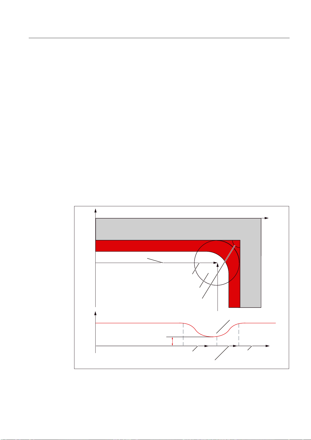
Motion commands
3.6 Controlling the feedrate
3.6 Controlling the feedrate
3.6.1 Automatic corner override G62
An inside corner with active tool radius compensation is often meaningful to reduce the
feedrate.
G62 operates only on internal corners with active tool radius compensation and active
continuous-path mode. Only the corners whose internal angle is smaller than MD42526
$SC_CORNER_SLOWDOWN_CRIT. The internal angle is defined from the bend in the
contour.
The feedrate is lowered by the factor from the setting data 42524
$SC_CORNER_SLOWDOWN_OVR:
traversed feedrate = F * $SC_CORNER_SLOWDOWN_OVR * feedrate override.
The feedrate override comprises of the feedrate override set in the machine control panel
multiplied with the override from synchronized actions.
The feedrate slowdown is started at the distance before the corner registered in the setting
data 42520 $SC_CORNER_SLOWDOWN_START. It ends with the distance after the corner
(see following Figure) registered in the setting data 42522
$SC_CORNER_SLOWDOWN_END. An appropriate path is used for curved contours.
<
:RUNSLHFH
/D\HUWREHPLOOHGRII
7RROFHQWHUSRLQWSDWK
6&B&251(5B6/2:'2:1B67$57
6&B&251(5B6/2:'2:1B(1'
,QWHUQDODQJOHื6&B&251(5B6/2:'2:1B&5,7
3DWKYHORFLW\Y
)
)6&B&251(5B6/2:'2:1B295
6&B&251(5B6/2:'2:1B67$57
6&B&251(5B6/2:'2:1B(1'
Figure 3-20 Parameter assignment of feedrate reduction G62 with the example of a 90°corner
)HHGVORZGRZQDWFRUQHU
3DWKV
;
ISO Milling
Programming Manual, 06/09, 6FC5398-7BP10-1BA0
69

Motion commands
3.6 Controlling the feedrate
Configuration
The override value is set over the following setting data:
42520: $SC_CORNER_SLOWDOWN_START
42522: $SC_CORNER_SLOWDOWN_END
42524: $SC_CORNER_SLOWDOWN_OVR
42526: $SC_CORNER_SLOWDOWN_CRIT
The setting data is preassigned with the value 0.
● If $SC_CORNER_SLOWDOWN_CRIT = 0, the corner deceleration is effective only at
reversal points.
● If $SC_CORNER_SLOWDOWN_START and $SC_CORNER_SLOWDOWN_END are
equal to 0, then the feedrate reduction is approached with the permissible dynamic
response.
● If $SC_CORNER_SLOWDOWN_OVR = 0, then a transient stop is inserted.
● $SC_CORNER_SLOWDOWN_CRIT is related to the geometry axes in G62. It defines the
maximum internal angle in the current machining plane up to which the corner
deceleration is used. G62 is not effective in rapid traverse.
Activating
Example
The function is activated via G62. The G code is active either via the corresponding part
program command or as default through MD20150 $MC_GCODE_RESET_VALUES[56].
Tool data in the Siemens mode
$TC_DP1[1,1]=120
$TC_DP3[1,1]=0 ; length compensation vector
$TC_DP4[1,1]=0.
$TC_DP5[1,1]=0.
Setting the setting data in the Siemens mode
N1000 G0 X0 Y0 Z0 F5000 G64 SOFT
N1010 STOPRE
N1020 $SC_CORNER_SLOWDOWN_START = 5.
N1030 $SC_CORNER_SLOWDOWN_END = 8.
N1040 $SC_CORNER_SLOWDOWN_OVR = 20.
N1050 $SC_CORNER_SLOWDOWN_CRIT = 100.
Program in the ISO mode
N2010 X00 Y30 G90 T1 D1 G64
N2020 X40 Y0 G62 G41 ;;Inner corner of N2030,
but WRK still selected
N2030 X80 Y30 ; Inner corner of N2040 127 degree
N2040 Y70 ; Inner corner of N2050 53 degree
N2050 X40 Y40 ; Outer corner of N2060
N2060 X20 Y70 ; Inner corner of N2070 97 degree
ISO Milling
70 Programming Manual, 06/09, 6FC5398-7BP10-1BA0

Motion commands
3.6 Controlling the feedrate
N2070 Y60 ; Inner corner of N2080 90 degree
N2080 X20 Y20 ;;Outer corner of N2090,
irrelevant due to WRK deselection
N2090 X00 Y00 G40 G64 ; Deselect G62 and on continuous-path mode
M30
3.6.2 Compressor in the ISO dialect mode
The commands COMPON, COMPCURV, COMPCAD are commands of the Siemens
language and they activate a compressor function that combines several linear blocks into
one machining section. If this function is activated in the Siemens mode, even linear blocks
in the ISO mode can be compressed with this function.
The blocks can at the most consist of the following commands:
● Block number
● G01, modal or in block
● Axis assignments
● Feedrate
● Comments
If a block contains other commands (e.g., auxiliary functions, other G codes, etc.), then
compression does not take place.
Value assignments with $x for G, axes and feedrate are possible, just as the skip function.
Example: These blocks are compressed
N5 G290
N10 COMPON
N15 G291
N20 G01 X100. Y100. F1000
N25 X100 Y100 F$3
N30 X$3 /1 Y100
N35 X100 (Axis 1)
These blocks are not compressed
N5 G290
N10 COMPON
N20 G291
N25 G01 X100 G17 ; G17
N30 X100 M22 ; Auxiliary function in block
N35 X100 S200 ; Spindle speed in block
ISO Milling
Programming Manual, 06/09, 6FC5398-7BP10-1BA0
71
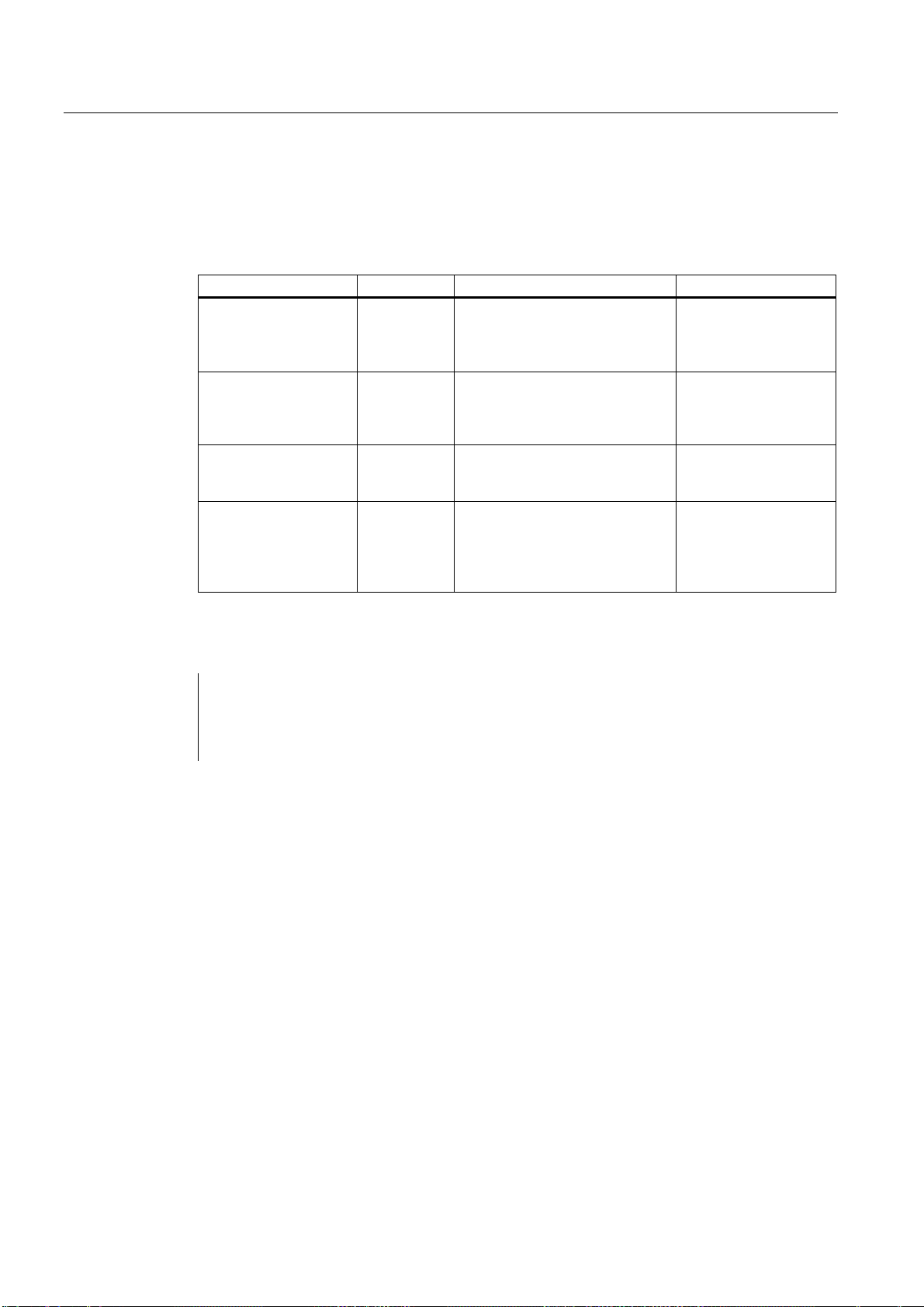
Motion commands
3.6 Controlling the feedrate
3.6.3 Exact stop (G09, G61), Continuous-path mode (G64), tapping (G63)
The path feedrate is controlled as specified in the table below.
Table 3- 15 Control of the path feedrate
Identifier G function Efficacy of the G functions Description
Exact stop G09 effective only in the block in which
the relevant G function is
programmed
Exact stop G61 Modal G function; remains
effective till it is deselected via
G62, G63 or G64.
Continuous-path mode G64 Modal G function; remains
effective till it is deselected via
G61, G62 or G63.
Tapping G63 Modal G function; remains
effective till it is deselected via
G61, G62 or G64.
Braking and stop at end
of block and position
control before transition
to the next block
Braking and stop at end
of block and position
control before transition
to the next block
No braking at end of
block before transition
to the next block
No braking at end of
block before transition
to the next block;
feedrate override is not
effective
Format
G09 X... Y... Z... ; Exact stop, non-modal
G61 ; Exact stop, modal
G64 ; Continuous-path mode
G63 ; Tapping
ISO Milling
72 Programming Manual, 06/09, 6FC5398-7BP10-1BA0

Additional functions
4.1 Program supporting functions
4.1.1 Fixed drilling cycles
The fixed drilling cycles simplify the creation of new programs for the programmer.
Frequently occurring machining steps can be executed with a G function; without fixed
cycles, several NC blocks must be programmed. Thus fixed drilling cycles shorten the
machining program and save memory space.
In the ISO dialect mode, a shell cycle is called which uses the functionality of the Siemens
standard cycles. This way, the addresses programmed in the NC block are transferred to the
shell cycle via system variables. The shell cycle adjusts this data and calls a Siemens
standard cycle.
The fixed drilling cycles are called with the following G functions.
Table 4- 1 Overview of drilling cycles
G function Drilling
(-Z direction)
G73 Interrupted working
feedrate (delay
possible at each infeed)
G74 Cutting feedrate Spindle stop →
G76 Cutting feedrate Spindle positioning
G80 — — — Deselection
G81 Cutting feedrate — Rapid traverse Drilling, Preboring
G82 Cutting feedrate Dwell Rapid traverse Drilling,
G83 Interrupted working
feedrate
G84 Cutting feedrate Spindle stop→
G85 Cutting feedrate — Cutting feedrate Drilling
G86 Cutting feedrate Spindle stop Rapid traverse →
Machining at drilling
base
— Rapid traverse High-speed deep
Spindle revolution
after dwelling in the
opposite direction
→ Withdraw lift-off
path
— Rapid traverse Deep-hole drilling
Spindle start after
dwelling in the
opposite direction
Return
(+Z direction)
Cutting feedrate →
dwell time → Spindle
turns in the opposite
direction
Rapid traverse →
Return lift-off path,
spindle start
Cutting feedrate →
dwell time → Spindle
turns in the opposite
direction
spindle start
4
Applications
hole drilling
Left-hand thread
boring (in the
opposite direction)
Precision drilling
boring
countersinking
Tapping
Drilling
ISO Milling
Programming Manual, 06/09, 6FC5398-7BP10-1BA0
73
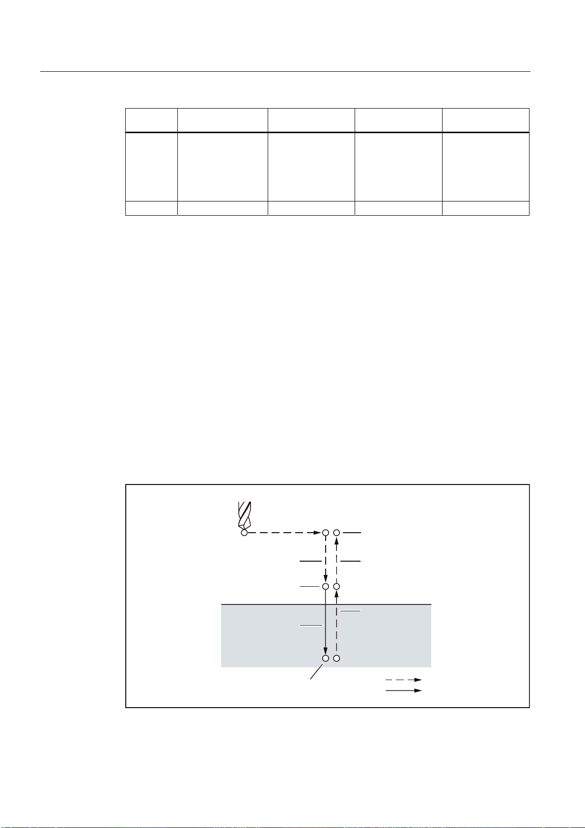
Additional functions
4.1 Program supporting functions
Explanations
G function Drilling
(-Z direction)
G87 Spindle positioning →
Withdraw lift-off path
→ Rapid traverse →
Return lift-off path →
Spindle run right →
Cutting feedrate
G89 Cutting feedrate Dwell Cutting feedrate Drilling
Machining at drilling
base
Spindle positioning
after dwelling →
Withdraw lift-off
path
Return
(+Z direction)
Rapid traverse →
Return lift-off path →
Spindle start
Applications
Drilling
On using fixed cycles, the sequence of operation in general is always as described below:
● 1. Working cycle
Positioning in X-Y plane with cutting feedrate or rapid traverse rate
● 2. Working cycle
Rapid traverse movement to plane R
● 3. Working cycle
Machining up to drilling depth Z
● 4. Working cycle
Machining at drilling base
● 5. Working cycle
Return up to plane R with cutting feedrate or rapid traverse rate
● 6. Working cycle
Rapid retraction with rapid traverse rate to positioning plane X-Y
:RUNLQJF\FOH
:RUNLQJF\FOH :RUNLQJF\FOH
3ODQH3RLQW5
:RUNLQJF\FOH
:RUNLQJF\FOH
Figure 4-1 Sequence of operations in the drilling cycle
,QLWLDOSODQH
:RUNLQJF\FOH
5DSLGWUDYHUVH
)HHG
ISO Milling
74 Programming Manual, 06/09, 6FC5398-7BP10-1BA0

Additional functions
4.1 Program supporting functions
If the term "drill" is used in this Chapter, it refers only to the working cycle that are executed
with the help of fixed cycles, even though naturally there are fixed cycles for tapping, boring
or drilling cycles too.
Definition of the current plane
In drilling cycles, one generally assumes that the current coordinate system in which the
machining operation is to be executed, is defined through the selection of plane G17, G18 or
G19 and activation of a programmable work offset. Drilling axis is then always the application
of this coordinate system.
Before calling the cycle, one must always select a tool length compensation. It is always
effective perpendicular to the selected plane and remains active even beyond the end of the
cycle.
Table 4- 2 Positioning plane and drilling axis
G function Positioning plane Drilling axis
G17 Xp-Yp plane Zp
G18 Zp-Xp plane Yp
G19 Yp-Zp plane Xp
Xp: X axis or an axis parallel to the X axis
Yp: Y axis or an axis parallel to the Y axis
Zp: Z axis or an axis parallel to the Z axis
Note
Whether the Z axis should always be used as the drilling axis can be defined with GUD7,
setting data _ZSFI[0]. The Z axis is then always the drilling axis, if _ZSFI[0] is equal to "1".
ISO Milling
Programming Manual, 06/09, 6FC5398-7BP10-1BA0
75

Additional functions
4.1 Program supporting functions
Execution of a fixed cycle
The following is necessary to execute a fixed cycle:
1. Cycle call
G73, 74, 76, 81 to 89
as a function of the desired machining
2. Data format G90/91
*DEVROXWHFRPPDQG
3RLQW5
3RLQW=
Figure 4-2 Absolute/incremental command G90/G91
5
=
=
*LQFUHPHQWDOFRPPDQG
5
3RLQW5
=
3RLQW=
ISO Milling
76 Programming Manual, 06/09, 6FC5398-7BP10-1BA0

Additional functions
4.1 Program supporting functions
3. Drilling mode
G73, G74, G76 and G81 to G89 are modal G functions and they remain active till they
are deselected. The selected drilling cycle is called in each block. The complete
parameter assignment of the drilling cycles must be programmed only during the
selection (e.g., G81). Only the parameters that are supposed to change are to be
programmed In the following blocks.
4. Positioning/reference plane (G98/G99)
While using the fixed cycles, the retraction plane for the Z-axis is defined with G98/99.
G98/G99 are modal G functions. The closed position is normally G98.
Repeat
*5HWXUQWRLQLWLDOSODQH
,QLWLDOSODQH
Figure 4-3 Plane for the return point (G98/G99)
*5HWXUQWRSODQH3RLQW5
3ODQH3RLQW5
If several holes are drilled at uniform spacing, the number of repetitions is specified with "K".
"K" is effective only in the block in which it is programmed. If the drilled hole position is
programmed as absolute (G90), drilling is done at the same position again; hence the drilled
hole position is to be specified as incremental (G91).
Comments
A cycle call remains active till it is deselected again with the G functions G80, G00, G01,
G02 or G03 or another cycle call.
ISO Milling
Programming Manual, 06/09, 6FC5398-7BP10-1BA0
77

Additional functions
4.1 Program supporting functions
Symbols and numbers
The individual fixed cycles are explained in the following sections. The following symbols are
used in the numbers occurring in these explanations:
3RVLWLRQLQJ5DSLGWUDYHUVH*
&XWWLQJIHHG/LQHDULQWHUSRODWLRQ*
0DQXDOIHHG
0
3
Figure 4-4 Icons in the numbers
2ULHQWHGVSLQGOHVWRS
7KHVSLQGOHVWRSVDWDGHILQHGURWDU\SRVLWLRQ
7UDYHUVH5DSLGWUDYHUVH*
'ZHOO
4.1.2 Deep hole drilling cycle with chip breakage (G73)
Format
The tool drills at the programmed spindle speed and feedrate to the entered final drilling
depth. Deep hole drilling is performed with a depth infeed of a maximum defined depth
executed several times, increasing gradually until the final drilling depth is reached.
Optionally, the twist drill can be retracted after each infeed depth either to the reference
plane + safety clearance for chip removal or by the length of the programmed retraction path
for chip breakage.
G73 X.. Y... R... Q... F... K... ;
X,Y: Drilled hole position
Z: Distance from Point R to the base of the drilled hole
R: Distance from the initial plane to plane R
Q: Single drilling depth
F: Feedrate
K: Number of repetitions
ISO Milling
78 Programming Manual, 06/09, 6FC5398-7BP10-1BA0

Additional functions
4.1 Program supporting functions
**
3RLQW5
T
**
,QLWLDOSODQH
3RLQW5 3ODQHಯ3RLQW5ಯ
T
G
T
G
T
T
T
G
G
Figure 4-5 Deep hole drilling cycle with chip breakage (G73)
Explanations
On using the G73 cycle, the retraction motion takes place after the drilling with rapid
traverse. The safety clearance can be specified with GUD _ZSFR[0]. The retraction amount
from chip breaking (d) is defined with GUD _ZSFR[1]:
_ZSFR[1] > 0 Retraction amount as input
_ZSFR[1] v 0 Retraction amount in chip breaking is always 1 mm
The in-feed takes place by using the cutting depth for each cutting Q which is incremented
with the retraction amount d as second in-feed.
A rapid drilling infeed results with this drilling cycle. Chip removal takes place through the
retraction motion.
ISO Milling
Programming Manual, 06/09, 6FC5398-7BP10-1BA0
3RLQW=
3RLQW=
79

Additional functions
4.1 Program supporting functions
Restrictions
Changeover of the axes
Before changing over the drilling axis, one must first deselect the fixed cycle.
Deep-hole drilling
The drilling cycle is executed only if an axis motion, e.g., is programmed with X, Y, Z or R.
Q/R
Always program Q and R in one block with an axis motion, otherwise the programmed
values will not be stored modally.
Deselection
The G functions of Group 01 (G00 to G03) and G73 should not be used together in one
block, as otherwise G73 is deselected
Example
M3 S1500 ;Rotary motion of stem
G90 G0 Z100
G90 G99 G73 X200. Y-150. Z-100.
R50. Q10. F150.
Y-500. ;Positioning, drilled hole 2,
Y-700. ;Positioning, drilled hole 3,
X950. ;Positioning, drilled hole 4,
Y-500. ;Positioning, drilled hole 5,
G98 Y-700. ;Positioning, drilled hole 6,
G80 ;Deselection of the fixed cycle
G28 G91 X0 Y0 Z0 ;Return to reference position
M5 ;Spindle stop
;Positioning, drilled hole 1,
;then return to Point R
;then return to Point R
;then return to Point R
;then return to Point R
;then return to Point R
;then return to initial plane
ISO Milling
80 Programming Manual, 06/09, 6FC5398-7BP10-1BA0
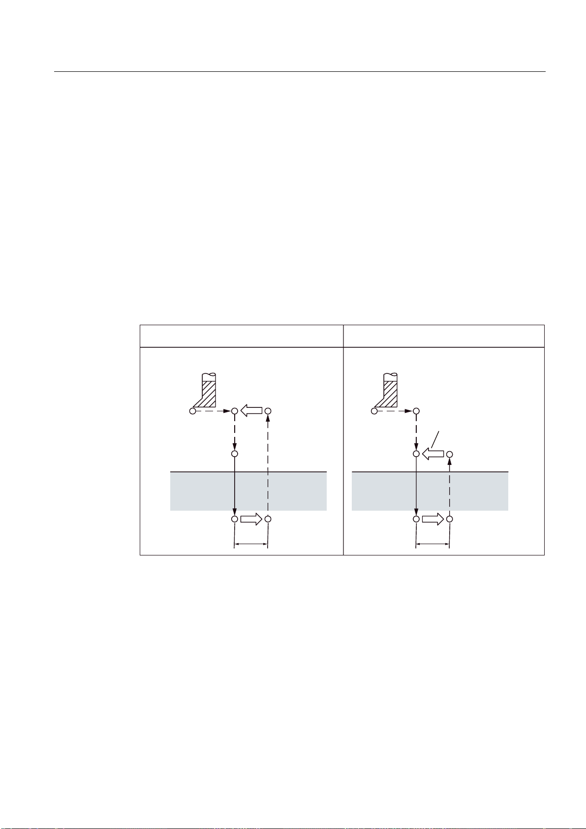
Additional functions
4.1 Program supporting functions
4.1.3 Fine drilling cycle (G76)
Precision drilling takes place with the fine drilling cycle.
Format
G76 X... Y... R... Q... P... F... K... ;
X,Y: Drilled hole position
Z_: Distance from point R to the bottom of the hole
R_: Distance from the initial plane to plane "Point R"
Q_: Amount of offset at the bottom of a hole
P_: Dwell time at the bottom of a hole
F_: Feedrate
K_: Number of repetitions
**
,QLWLDOSODQH
3RLQW5
3
0
Figure 4-6 Fine drilling cycle (G76)
3RLQW=
T
**
3RLQW5
0
6SLQGOHFRXQWHUFORFNZLVH
3ODQHಯ3RLQW5ಯ
3
3RLQW=
T
ISO Milling
Programming Manual, 06/09, 6FC5398-7BP10-1BA0
81
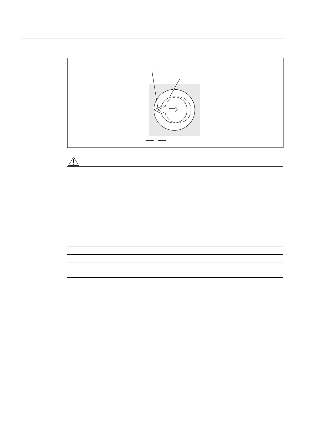
Additional functions
4.1 Program supporting functions
2ULHQWHGVSLQGOHVWRS
7RRO
2IIVHWT
Explanations
WARNING
Address Q is a modal value that is stored in fixed cycles. Please ensure that this address is
also used as interface for the cycles G73 and G83!
The spindles stops at a fixed spindle position after the bottom of a hole is reached. The tool
is returned opposite the tool tip.
The safety clearance can be specified with GUD _ZSFR[0]. The lift-off path can be specified
with _ZSFI[5].
G17 G18 G19
_ZSFI[5] = 1 +X +Z +Y
_ZSFI[5] = 0 or 2 -X -Z -Y
_ZSFI[5] = 3 +Y +X +Z
_ZSFI[5] = 4 -Y -X -Z
The angle must therefore be specified in GUD7 _ZSFR[2] in such a way that the tool tip
points at the opposite direction after the spindle stop, for the lift-off path.
Restrictions
Changeover of the axes
Before changing over the drilling axis, one must first deselect the fixed cycle.
Drilling
The drilling cycle is executed only if an axis motion, e.g. is programmed with X, Y, Z or R.
ISO Milling
82 Programming Manual, 06/09, 6FC5398-7BP10-1BA0

Additional functions
4.1 Program supporting functions
Q/R
Always program Q and R only in one block with a retracting movement, otherwise the
programmed values are not stored modally.
Only one positive value is to be specified in each case for the value of Address Q. If a
negative value is specified for Q, the sign is ignored. Q is set as equal to "0" if no lift-off path
is programmed. In this case, the cycle is executed without lifting.
Deselection
The G functions of Group 01 (G00 to G03) and G76 should not be used together in one
block, as otherwise G76 is deselected.
Example
M3 S300 ;Rotary motion of stem
G90 G0 Z100
G90 G99 G76 X200. Y-150. Z-100.
R50. Q10. P1000 F150.
Y-500. ;Positioning, drilled hole 2,
Y-700. ;Positioning, drilled hole 3,
X950. ;Positioning, drilled hole 4,
Y-500. ;Positioning, drilled hole 5,
G98 Y-700. ;Positioning, drilled hole 6,
G80 ;Deselection of the fixed cycle
G28 G91 X0 Y0 Z0 ;Return to reference position
M5 ;Spindle stop
;Positioning, drilling of drilled hole 1,
;then return to point R and
;for 1 s stop at the bottom of a hole
;then return to point R
;then return to point R
;then return to point R
;then return to point R
;then return to initial plane
ISO Milling
Programming Manual, 06/09, 6FC5398-7BP10-1BA0
83
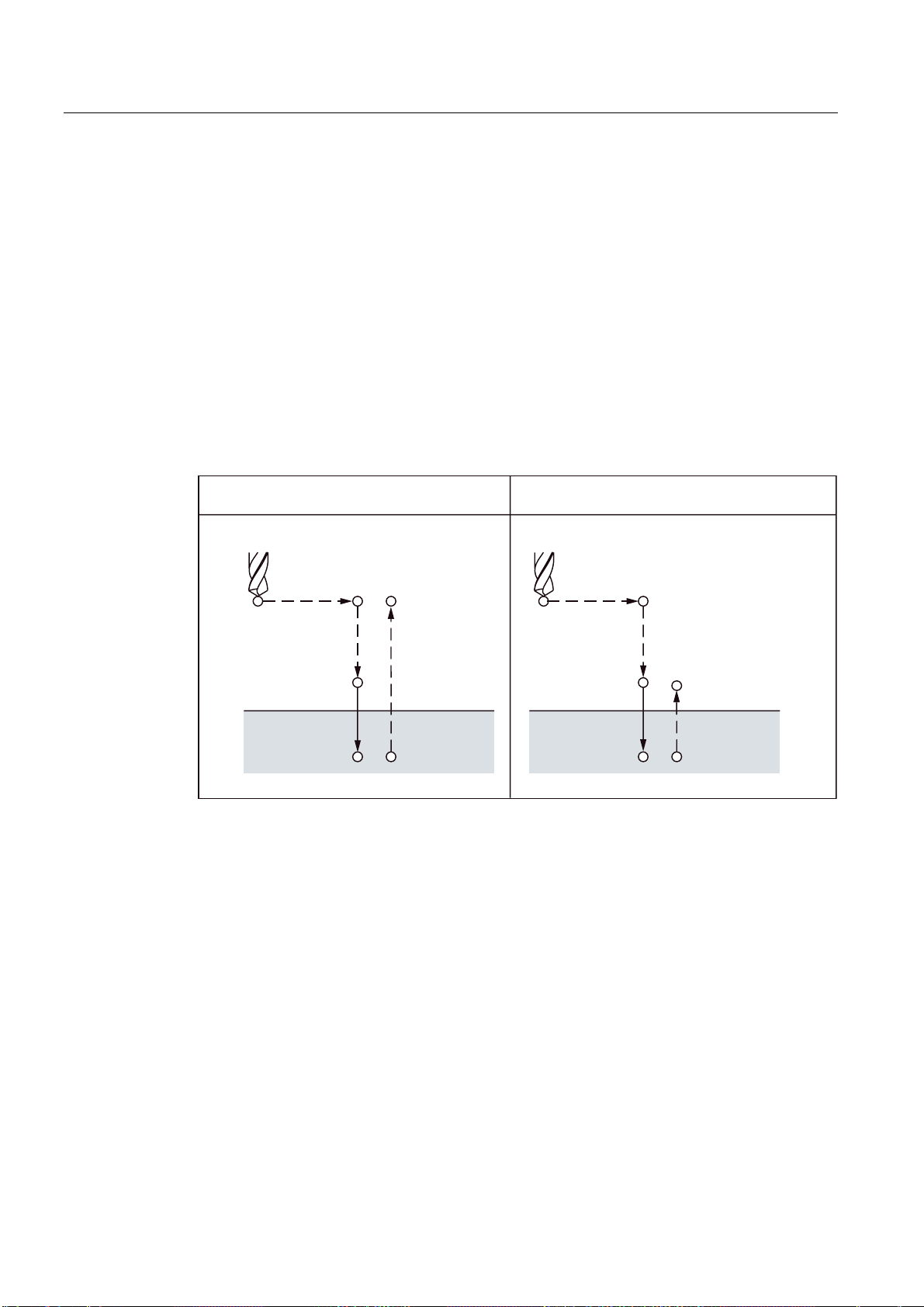
Additional functions
4.1 Program supporting functions
4.1.4 Drilling cycle, preboring (G81)
This cycle can be used for centering and preboring. The retraction motion starts immediately
with rapid traverse rate on reaching the drilling depth Z.
Format
G81 X... Y... R... F... K... ;
X,Y: Drilled hole position
Z: Distance from point R to the bottom of the hole
R: Distance from the initial plane to plane R
F: Cutting feedrate
K: Number of repetitions
**
Figure 4-7 Drilling cycle, preboring (G81)
Restrictions
Changeover of the axes
Before changing over the drilling axis, one must first deselect the fixed cycle.
3RLQW5
,QLWLDOSODQH
3RLQW=
**
3RLQW5
3ODQHಯ3RLQW5ಯ
3RLQW=
Drilling
The drilling cycle is executed only if an axis motion, e.g. is programmed with X, Y, Z or R.
R
Always program R only in one block with an axis motion, otherwise the programmed values
are not stored modally.
ISO Milling
84 Programming Manual, 06/09, 6FC5398-7BP10-1BA0

Additional functions
4.1 Program supporting functions
Deselection
The G functions of Group 01 (G00 to G03) and G76 should not be used together in one
block, as otherwise G76 is deselected.
Example
M3 S1500 ;Rotary motion of stem
G90 G0 Z100
G90 G99 G81 X200. Y-150. Z-100.
R50. F150.
Y-500. ;Positioning, drilled hole 2,
Y-700. ;Positioning, drilled hole 3,
X950. ;Positioning, drilled hole 4,
Y-500. ;Positioning, drilled hole 5,
G98 Y-700. ;Positioning, drilled hole 6,
G80 ;Deselection of the fixed cycle
G28 G91 X0 Y0 Z0 ;Return to reference position
M5 ;Spindle stop
;Positioning, drilled hole 1,
;then return to point R and
;for 1 s stop at the bottom of a hole
;then return to point R
;then return to point R
;then return to point R
;then return to point R
;then return to initial plane
4.1.5 Drilling cycle, preboring (G82)
This cycle can be used for normal drilling. A programmed dwell time can be active on
reaching the drilling depth Z; the retraction motion is then executed in rapid traverse.
Format
G82 X... Y... R... P... F... K... ;
X,Y: Drilled hole position
Z: Distance from point R to the bottom of the hole
R: Distance from the initial plane to plane R
P: Dwell time at the bottom of a hole
F: Feedrate
K: Number of repetitions
ISO Milling
Programming Manual, 06/09, 6FC5398-7BP10-1BA0
85

Additional functions
4.1 Program supporting functions
**
Figure 4-8 Drilling cycle, countersink cycle (G82)
Restrictions
Changeover of the axes
Before changing over the drilling axis, one must first deselect the fixed cycle.
3RLQW5
,QLWLDOSODQH
3RLQW=
**
3RLQW5
3ODQHಯ3RLQW5ಯ
3RLQW=
Drilling
R
Deselection
Example
The drilling cycle is executed only if an axis motion, e.g. is programmed with X, Y, Z or R.
Always program R only in one block with an axis motion, otherwise the programmed values
are not stored modally.
The G functions of Group 01 (G00 to G03) and G82 should not be used together in one
block, as otherwise G82 is deselected.
M3 S2000 ;Rotary motion of stem
G90 G0 Z100
G90 G99 G82 X200. Y-150. Z-100.
R50. P1000 F150.
Y-500. ;Positioning, drilled hole 2,
;Positioning, drilled hole 1,
;stop on the bottom of a hole for 1 s
;then return to point R
ISO Milling
86 Programming Manual, 06/09, 6FC5398-7BP10-1BA0

Additional functions
4.1 Program supporting functions
;then return to point R
Y-700. ;Positioning, drilled hole 3,
;then return to point R
X950. ;Positioning, drilled hole 4,
;then return to point R
Y-500. ;Positioning, drilled hole 5,
;then return to point R
G98 Y-700. ;Positioning, drilled hole 6,
;then return to initial plane
G80 ;Deselection of the fixed cycle
G28 G91 X0 Y0 Z0 ;Return to reference position
M5 ;Spindle stop
4.1.6 Deep hole drilling cycle with chip removal (G83)
The cycle "Deep hole drilling with chips removal" can, e.g., be used for deep hole drilling with
recutting.
Format
G83 X... Y... R... Q... F... K... ;
X,Y: Drilled hole position
Z: Distance from point R to the bottom of the hole
R: Distance from the initial plane to plane R
Q: Cutting depth for each cutting feedrate
F: Feedrate
K: Number of repetitions
ISO Milling
Programming Manual, 06/09, 6FC5398-7BP10-1BA0
87

Additional functions
4.1 Program supporting functions
** **
,QLWLDOSODQH
Restrictions
Explanations
3RLQW5
T
T
T
Figure 4-9 Deep hole drilling cycle with chip removal (G83)
G
G
3RLQW=
3RLQW5
T
T
T
3ODQHಯ3RLQW5ಯ
G
G
3RLQW=
After the programmed cutting depth is reached for each cutting feedrate Q, the return to the
reference plane R takes place in rapid traverse. The approach motion for a renewed step is
also executed in rapid traverse, around the path (d) that can be set in GUD7 _ZSFR[10]. The
path and the cutting depth for each cutting feedrate Q are traversed with cutting feedrate. Q
is incremental without having to specify signs.
Changeover of the axes
Before changing over the drilling axis, one must first deselect the fixed cycle.
Drilling
The drilling cycle is executed only if an axis motion, e.g. X, Y, Z or R is programmed.
Q/R
Always program Q and R in one block with an axis motion, otherwise the programmed
values will not be stored modally.
Deselection
The G functions of Group 01 (G00 to G03) and G83 should not be used together in one
block, as otherwise G83 is deselected.
ISO Milling
88 Programming Manual, 06/09, 6FC5398-7BP10-1BA0

Additional functions
4.1 Program supporting functions
Example
M3 S2000 ;Rotary motion of stem
G90 G0 Z100
G90 G99 G83 X200. Y-150. Z-100.
R50. Q10. F150.
Y-500. ;Positioning, drilled hole 2,
Y-700. ;Positioning, drilled hole 3,
X950. ;Positioning, drilled hole 4,
Y-500. ;Positioning, drilled hole 5,
G98 Y-700. ;Positioning, drilled hole 6,
G80 ;Deselection of the fixed cycle
G28 G91 X0 Y0 Z0 ;Return to reference position
M5 ;Spindle stop
;Positioning, drilled hole 1,
;then return to point R
;then return to point R
;then return to point R
;then return to point R
;then return to point R
;then return to initial plane
Note
If _ZSFR[10]
• > 0 = Value is used for the derivative path "d" (minimum distance 0.001)
• = 0 The derivative path is 30 mm and the value of the derivative path is always 0.6 mm.
The drilling depth/50 formula is always used for larger drilling depths (maximum value 7
mm).
ISO Milling
Programming Manual, 06/09, 6FC5398-7BP10-1BA0
89

Additional functions
4.1 Program supporting functions
4.1.7 Drilling cycle (G85)
Format
G85 X... Y... R... F... K... ;
X,Y: Drilled hole position
Z: Distance from point R to the bottom of the hole
R: Distance from the initial plane to plane R
F: Feedrate
K: Number of repetitions
** **
,QLWLDOSODQH
Figure 4-10 Drilling cycle (G85)
Explanations
A traversing movement takes place to point R in rapid traverse after the positioning along the
X and Y axis. Drilling takes place from point R to point Z. On reaching point Z, a retraction
motion to point R takes place with cutting feedrate.
Restrictions
Changeover of the axes
Before changing over the drilling axis, one must first deselect the fixed cycle.
3RLQW5
3RLQW=
3RLQW5
3ODQHಯ3RLQW5ಯ
3RLQW=
Drilling
The drilling cycle is executed only if an axis motion, e.g. is programmed with X, Y, Z or R.
ISO Milling
90 Programming Manual, 06/09, 6FC5398-7BP10-1BA0

Additional functions
4.1 Program supporting functions
R
Always program R only in one block with an axis motion, otherwise the programmed values
are not stored modally.
Deselection
The G functions of Group 01 (G00 to G03) and G85 should not be used together in one
block, as otherwise G85 is deselected.
Example
M3 S150 ;Rotary motion of stem
G90 G0 Z100
G90 G99 G85 X200. Y-150. Z-100.
R50. F150.
Y-500. ;Positioning, drilled hole 2,
Y-700. ;Positioning, drilled hole 3,
X950. ;Positioning, drilled hole 4,
Y-500. ;Positioning, drilled hole 5,
G98 Y-700. ;Positioning, drilled hole 6,
G80 ;Deselection of the fixed cycle
G28 G91 X0 Y0 Z0 ;Return to reference position
M5 ;Spindle stop
;Positioning, drilled hole 1,
;then return to point R
;then return to point R
;then return to point R
;then return to point R
;then return to point R
;then return to initial plane
4.1.8 Boring cycle (G86)
Format
G86 X... Y... R... F... K... ;
X,Y: Drilled hole position
Z: Distance from point R to the bottom of the hole
R: Distance from the initial plane to point R
F: Feedrate
K: Number of repetitions
ISO Milling
Programming Manual, 06/09, 6FC5398-7BP10-1BA0
91

Additional functions
4.1 Program supporting functions
** **
6SLQGOH
&RXQWHUFORFNZLVH
Explanations
Restrictions
,QLWLDOSODQH
3RLQW5
3
Figure 4-11 Boring cycle (G86)
3RLQW=
6SLQGOHVWRS
3RLQW5
3
6SLQGOH
&RXQWHUFORFNZLVH
3ODQHಯ3RLQW5ಯ
3RLQW=
6SLQGOHVWRS
Point R is approached in rapid traverse after positioning the X and Y axes. Drilling takes
place from point R to point Z. The tool returns in rapid traverse mode after the spindle is
stopped at the bottom of a hole.
Changeover of the axes
Before changing over the drilling axis, one must first deselect the fixed cycle.
Drilling
The drilling cycle is executed only if an axis motion, e.g. is programmed with X, Y, Z or R.
R
Always program R only in one block with an axis motion, otherwise the programmed values
are not stored modally.
Deselection
The G functions of Group 01 (G00 to G03) and G86 should not be used together in one
block, as otherwise G86 is deselected.
ISO Milling
92 Programming Manual, 06/09, 6FC5398-7BP10-1BA0

Additional functions
4.1 Program supporting functions
Example
M3 S150 ;Rotary motion of stem
G90 G0 Z100
G90 G99 G86 X200. Y-150. Z-100.
R50. F150.
Y-500. ;Positioning, drilled hole 2,
Y-700. ;Positioning, drilled hole 3,
X950. ;Positioning, drilled hole 4,
Y-500. ;Positioning, drilled hole 5,
G98 Y-700. ;Positioning, drilled hole 6,
G80 ;Deselection of the fixed cycle
G28 G91 X0 Y0 Z0 ;Return to reference position
M5 ;Spindle stop
;Positioning, drilled hole 1,
;then return to point R
;then return to point R
;then return to point R
;then return to point R
;then return to point R
;then return to initial plane
4.1.9 Boring cycle, reverse countersinking (G87)
This cycle can be used for precision drilling.
Format
G87 X... Y... R... Q... P... F... K... ;
X,Y: Drilled hole position
Z: Distance from bottom of the hole to point Z
R: Distance from the initial plane to plane R (bottom of a hole)
Q: Tool offset amount
P: Dwell time
F: Feedrate
K: Number of repetitions
ISO Milling
Programming Manual, 06/09, 6FC5398-7BP10-1BA0
93

Additional functions
4.1 Program supporting functions
**
T
0
6SLQGOHFRXQWHUFORFNZLVH
0
3RLQW=
S
6SLQGOHFRXQWHUFORFNZLVH
3RLQW5
Figure 4-12 Boring cycle, reverse countersinking (G87)
2ULHQWHGVSLQGOHVWRS
7RRO
**
,VQRWXVHG
2IIVHWT
WARNING
Address Q (gear change at the base of a drilled hole) is a modal value that is stored in fixed
cycles. Please ensure that this address is also used as interface for the cycles G73 and
G83!
ISO Milling
94 Programming Manual, 06/09, 6FC5398-7BP10-1BA0

Additional functions
4.1 Program supporting functions
Explanations
The spindle stops at a fixed rotary position after positioning along the X and Y axis. The tool
travels in the direction opposite to that of the tool tip. It is positioned on the bottom of a hole
(Point R) at rapid traverse.
Finally, the tool is shifted in the direction of the tool tip and the spindle is moved with
clockwise rotation. Drilling takes place along the Z axis in the positive direction up to point Z.
The spindles stops at a fixed spindle position after the bottom of a hole is reached. The tool
is returned opposite the tool tip.
The safety clearance can be specified with GUD _ZSFR[0].
The lift-off path can be specified with _ZSFI[5].
G17 G18 G19
_ZSFR[5] = 1 +X +Z +Y
_ZSFI[5] = 0 or 2 -X -Z -Y
_ZSFI[5] = 3 +Y +X +Z
_ZSFI[5] = 4 -Y -X -Z
The angle must therefore be specified in GUD7 _ZSFR[2] in such a way that the tool tip
points at the opposite direction after the spindle stop for the lift-off path.
Example:
If plane G17 is activated, the tool tip must point in direction +X.
Restrictions
Changeover of the axes
Before changing over the drilling axis, one must first deselect the fixed cycle.
Drilling
The drilling cycle is executed only if an axis motion, e.g. is programmed with X, Y, Z or R.
Q/R
Always program Q and R in one block with an axis motion, otherwise the programmed
values will not be stored modally.
Only one positive value is to be specified in each case for the value of Address Q. If a
negative value is specified for "Q", the sign is ignored. "Q" is set as equal to "0" if no lift-off
path is programmed. In this case, the cycle is executed without lifting.
ISO Milling
Programming Manual, 06/09, 6FC5398-7BP10-1BA0
95

Additional functions
4.1 Program supporting functions
Deselection
The G functions of Group 01 (G00 to G03) and G87 should not be used together in one
block, as otherwise G87 is deselected.
Example
M3 S400 ;Rotary motion of stem
G90 G0 Z100
G90 G87 X200. Y-150. Z-100.
R50. Q3. P1000 F150.
Y-500. ;Positioning, drilled hole 2
Y-700. ;Positioning, drilled hole 3
X950. ;Positioning, drilled hole 4
Y-500. ;Positioning, drilled hole 5
G98 Y-700. ;Positioning, drilled hole 6
G80 ;Deselection of the fixed cycle
G28 G91 X0 Y0 Z0 ;Return to reference position
M5 ;Spindle stop
;Positioning, drilled hole 1,
;orientation towards initial plane,
;then travel 3 mm,
;halt for 1 s at point Z
4.1.10 Drilling cycle (G89), return with G01
Format
G89 X... Y... R... P... F... K... ;
X,Y: Drilled hole position
Z: Distance from point R to the bottom of the hole
R: Distance from the initial plane to point R
P: Dwell time at the bottom of a hole
F: Feedrate
K: Number of repetitions
ISO Milling
96 Programming Manual, 06/09, 6FC5398-7BP10-1BA0

Additional functions
4.1 Program supporting functions
** **
,QLWLDOSODQH
3ODQHಯ3RLQW5ಯ
3RLQW5
3RLQW5
Figure 4-13 Boring cycle (G89)
Explanations
This cycle is similar to G86, with the only exception that here, a dwell time at the bottom of
the hole is still available.
Before programming G89, the spindle must be started with an M function.
Restrictions
Changeover of the axes
Before changing over the drilling axis, one must first deselect the fixed cycle.
Drilling
The drilling cycle is executed only if an axis motion, e.g. is programmed with X, Y, Z or R.
3
3RLQW=
3
3RLQW=
R
Always program R only in one block with an axis motion, otherwise the programmed values
are not stored modally.
Deselection
The G functions of Group 01 (G00 to G03) and G89 should not be used together in one
block, as otherwise G89 is deselected.
ISO Milling
Programming Manual, 06/09, 6FC5398-7BP10-1BA0
97

Additional functions
4.1 Program supporting functions
Example
M3 S150 ;Rotary motion of stem
G90 G0 Z100
G90 G99 G89 X200. Y-150. Z-100.
R50. P1000 F150.
Y-500. ;Positioning, drilled hole 2,
Y-700. ;Positioning, drilled hole 3,
X950. ;Positioning, drilled hole 4,
Y-500. ;Positioning, drilled hole 5,
G98 Y-700. ;Positioning, drilled hole 6,
G80 ;Deselection of the fixed cycle
G28 G91 X0 Y0 Z0 ;Return to reference position
M5 ;Spindle stop
;Positioning, drilled hole 1,
;then 1 s stop at the bottom of a hole
;then return to point R
;then return to point R
;then return to point R
;then return to point R
;then return to initial plane
4.1.11 Cycle "Tapping without compensating chuck" (G84)
The tool drills at the programmed spindle speed and feedrate to the entered final thread
Format
depth. With G84 you can produce rigid tapping.
Note
G84 can be used if the spindle to be used for the drilling operation is technically able to be
operated in the position-controlled spindle mode.
G84 X... Y... Z... R... P... F... K... ;
X,Y: Drilled hole position
Z: Distance from point R to the bottom of the hole
R: Distance from the initial plane to plane R
P: Dwell time at the bottom of the hole and at point R during return
F: Cutting feedrate
K: Number of repetitions (if necessary)
ISO Milling
98 Programming Manual, 06/09, 6FC5398-7BP10-1BA0

Additional functions
4.1 Program supporting functions
** **
Explanations
6SLQGOHVWRS
,QLWLDOSODQH
6SLQGOHFRXQWHUFORFNZLVH 6SLQGOHFRXQWHUFORFNZLVH
3RLQW5 3RLQW5
6SLQGOHVWRS
Figure 4-14 Tapping without compensating chuck (G84)
6SLQGOHFRXQWHUFORFNZLVH 6SLQGOHFRXQWHUFORFNZLVH
6SLQGOHVWRS
33
3RLQW= 3RLQW=
33
6SLQGOHFRXQWHUFORFNZLVH
6SLQGOHVWRS
6SLQGOHVWRS
3ODQHಯ3RLQW5ಯ
The cycle creates the following sequence of motions:
● Approach of reference plane shifted by the amount of the safety clearance with G0.
● Oriented spindle stop and transfer of spindle in the Axis mode.
● Tapping to the final drilling depth.
● Execution of dwell time at thread depth.
● Retraction to the reference plane and reversion of direction of rotation brought forward by
the safety clearance.
● Retraction to the retraction plane with G0.
During tapping, rapid traverse override and spindle override are accepted at 100%.
The speed of rotation can be affected during the retraction with GUD _ZSFI[2]. Example:
_ZSFI[2]=120; the retraction takes place at 120% of the speed during tapping.
Restrictions
Changeover of the axes
Before changing over the drilling axis, one must first deselect the fixed cycle. An alarm is
output if the drilling axis in the "Drilling without compensating chuck" mode is changed over.
ISO Milling
Programming Manual, 06/09, 6FC5398-7BP10-1BA0
99

Additional functions
4.1 Program supporting functions
Tapping
The drilling cycle is executed only if an axis motion, e.g. is programmed with X, Y, Z or R.
R
Always program R only in one block with an axis motion, otherwise the programmed values
are not stored modally.
Deselection
The G functions of Group 01 (G00 to G03) and G84 should not be used together in one
block, as otherwise G84 is deselected.
S command
An error message is displayed if the specified gear stage is one step higher than the
maximum permissible value.
F function
An error message is displayed if the value specified for the cutting feedrate exceeds the
maximum permissible value.
Unit of the F command
Metric input Input in inch Remarks
G94 1 mm/min 0.01 inch/min Decimal point programming is
G95 0.01 mm/rev 0.0001 inch/rev Decimal point programming is
Example
Feedrate for the Z axis 1.000 mm/min
Spindle speed 1,000 rev/min
Thread lead 1.0 mm
<Programming as feedrate per minute>
S100 M3
G94 ;Feedrate per minute
G00 X100.0 Y100.0 ;Positioning
G84 Z-50.0 R-10.0 F1000 ;Tapping without compensating chuck
<Programming as revolutional feedrate>
G95 ; Rev. feedrate
G98 Y-700. ;Positioning, drilled hole 6,
permitted
permitted
ISO Milling
100 Programming Manual, 06/09, 6FC5398-7BP10-1BA0
 Loading...