


 Loading...
SINUMERIK
SINUMERIK 828D PPU
Manual
Preface
Safety notes |
1 |
|
|
System description |
2 |
|
|
Application planning |
3 |
|
|
Installing |
4 |
|
|
Rulesforpermittedtopologies |
5 |
|
|
Interface description |
6 |
|
|
Connectable components |
7 |
|
|
Technical data |
8 |
|
|
Spare parts and accessories |
9 |
|
|
Appendix |
A |
Valid for: SINUMERIK 828D PPU 24x.3 BASIC PPU 26x.3 PPU 28x.3
01/2014
6FC5397-2DP40-3BA3

Legal information
Warning notice system
This manual contains notices you have to observe in order to ensure your personal safety, as well as to prevent damage to property. The notices referring to your personal safety are highlighted in the manual by a safety alert symbol, notices referring only to property damage have no safety alert symbol. These notices shown below are graded according to the degree of danger.
 DANGER
indicates that death or severe personal injury will result if proper precautions are not taken.
 WARNING
indicates that death or severe personal injury may result if proper precautions are not taken.
 CAUTION
indicates that minor personal injury can result if proper precautions are not taken.
NOTICE
indicates that property damage can result if proper precautions are not taken.
If more than one degree of danger is present, the warning notice representing the highest degree of danger will be used. A notice warning ofinjuryto persons with a safety alert symbol may also include a warning relating toproperty damage.
Qualified Personnel
The product/system described in this documentation may be operated only by personnel qualified for the specific taskinaccordancewiththerelevantdocumentation,inparticularitswarningnoticesandsafetyinstructions.Qualified personnel are those who, based on their training and experience, are capable of identifying risks and avoiding potential hazards when working with these products/systems.
Proper use of Siemens products
Note the following:
 WARNING
Siemens products may only be used for the applications described in the catalog and in the relevant technical documentation. If products and components from other manufacturers are used, these must be recommended or approved by Siemens. Proper transport, storage, installation, assembly, commissioning, operation and maintenance are required to ensure that the products operate safely and without any problems. The permissible ambient conditions must be complied with. The information in the relevant documentation must be observed.
Trademarks
All names identified by ® are registered trademarks of Siemens AG. The remaining trademarks in this publication may be trademarks whose use by third parties for their own purposes could violate the rights of the owner.
Disclaimer of Liability
We have reviewed the contents of this publication to ensure consistency with the hardware and software described. Since variance cannot be precluded entirely, we cannot guarantee full consistency. However, the information in this publication is reviewed regularly and any necessary corrections are included in subsequent editions.
Siemens AG |
Order number: 6FC5397-2DP40-3BA3 |
Copyright © Siemens AG 2009 - 2014. |
Industry Sector |
01/2014 Technical data subject to change |
All rights reserved |
Postfach 48 48 |
|
|
90026 NÜRNBERG |
|
|
GERMANY |
|
|
Preface
SINUMERIK documentation
The SINUMERIK documentation is organized into the following categories:
●General documentation
●User documentation
●Manufacturer/service documentation
Additional information
You can find information on the following topics under the link (www.siemens.com/ motioncontrol/docu):
●Ordering documentation / current documentation overview
●Additional links to download documents
●Using documentation online (finding and searching in manuals/information)
Please send any questions about the technical documentation (e.g. suggestions for improvement, corrections) to the following address: (mailto:docu.motioncontrol@siemens.com)
My Documentation Manager (MDM)
Under the following link you will find information to individually compile OEM-specific machine
documentation based on the Siemens content: MDM (www.siemens.com/mdm)
Training
For information about the range of training courses, refer to:
●SITRAIN (www.siemens.com/sitrain) - training courses from Siemens for automation products, systems and solutions
●SinuTrain (www.siemens.com/sinutrain) - training software for SINUMERIK
FAQs
You can find Frequently Asked Questions in the Service&Support pages under Product
Support (www.siemens.com/automation/service&support).
PPU |
3 |
Manual, 01/2014, 6FC5397-2DP40-3BA3 |

Preface
SINUMERIK
You can find information on SINUMERIK under the following link: (www.siemens.com/ sinumerik)
Target group
This documentation is intended for manufacturers of machine tools, particularly:
●Project engineers, electricians and installers
●Maintenance and service personnel
Benefits
The information in this manual facilitates installation and connection of the SINUMERIK 828D numerical control.
Standard version
This documentation only describes the functionality of the standard version. Extensions or changes made by the machine manufacturer are documented by the machine manufacturer.
Other functions not described in this documentation might be executable in the control. However, no claim can be made regarding the availability of these functions when the equipment is first supplied or in the event of servicing.
Further, for the sake of simplicity, this documentation does not contain all detailed information aboutalltypesoftheproductandcannotcovereveryconceivablecaseofinstallation,operation or maintenance.
Technical support
Country-specific telephone numbers for technical support are provided in the Internet under "Contact" (www.siemens.com/automation/service&support).
EC Declaration of Conformity
The EC declaration of conformity for the EMC directive can be found in the Internet (http:// support.automation.siemens.com/WW/view/de/10805517/134200).
4 |
PPU |
Manual, 01/2014, 6FC5397-2DP40-3BA3 |
Table of contents
|
Preface......................................................................................................................................................... |
|
3 |
1 |
Safety notes.................................................................................................................................................. |
9 |
|
|
1.1 |
Danger notices.............................................................................................................................. |
9 |
|
1.2 |
ESD notices................................................................................................................................. |
11 |
2 |
System description..................................................................................................................................... |
13 |
|
|
2.1 |
Controller features....................................................................................................................... |
13 |
|
2.2 |
PPU version 24x.3 BASIC........................................................................................................... |
15 |
|
2.3 |
PPU versions 26x.3 and 28x.3.................................................................................................... |
18 |
|
2.4 |
Operator controls and display elements...................................................................................... |
21 |
|
2.5 |
Type plate.................................................................................................................................... |
22 |
|
2.6 |
System overview......................................................................................................................... |
24 |
|
2.7 |
Connectable components............................................................................................................ |
26 |
|
2.8 |
Ordering data.............................................................................................................................. |
27 |
|
2.9 |
CompactFlash Cards................................................................................................................... |
29 |
|
2.9.1 |
CompactFlash card system......................................................................................................... |
29 |
|
2.9.2 |
Inserting the system CompactFlash Card................................................................................... |
30 |
|
2.9.3 |
CompactFlash card for user data................................................................................................ |
32 |
3 |
Application planning................................................................................................................................... |
35 |
|
|
3.1 |
Secondary electrical conditions................................................................................................... |
35 |
|
3.1.1 |
Protective Separation as per EN 61800-5-1................................................................................ |
35 |
|
3.1.2 |
Grounding concept...................................................................................................................... |
35 |
|
3.1.3 |
RI suppression measures............................................................................................................ |
37 |
|
3.2 |
Climatic and mechanical environmental conditions..................................................................... |
39 |
|
3.2.1 |
Ambient conditions...................................................................................................................... |
39 |
|
3.2.2 |
Transport and Storage Conditions.............................................................................................. |
39 |
|
3.2.3 |
Operating Conditions................................................................................................................... |
40 |
|
3.3 |
Recycling and disposal................................................................................................................ |
41 |
4 |
Installing..................................................................................................................................................... |
|
43 |
|
4.1 |
Mounting positions...................................................................................................................... |
43 |
|
4.2 |
Dimension drawings.................................................................................................................... |
50 |
5 |
Rules for permitted topologies.................................................................................................................... |
53 |
|
|
5.1 |
Topology rules for S120 Combi................................................................................................... |
53 |
|
5.2 |
Topology rules for S120 Booksize............................................................................................... |
54 |
|
5.3 |
Topology rules for Safety Integrated functions............................................................................ |
58 |
PPU |
5 |
Manual, 01/2014, 6FC5397-2DP40-3BA3 |

Table of contents
|
5.4 |
Topology example without Safety Integrated functions............................................................... |
59 |
|
5.5 |
Topology example with Safety Integrated functions.................................................................... |
63 |
6 |
Interface description................................................................................................................................... |
67 |
|
|
6.1 |
Interface overview....................................................................................................................... |
67 |
|
6.2 |
Power supply connection............................................................................................................ |
69 |
|
6.2.1 |
Requirements for the power supply............................................................................................. |
69 |
|
6.2.2 |
Connecting the power supply...................................................................................................... |
71 |
|
6.3 |
Ethernet....................................................................................................................................... |
71 |
|
6.4 |
PLC I/O Interface based on PROFINET ..................................................................................... |
73 |
|
6.4.1 |
Addressing the I/O modules........................................................................................................ |
75 |
|
6.5 |
Digital inputs/outputs................................................................................................................... |
76 |
|
6.5.1 |
Terminal connection diagram...................................................................................................... |
81 |
|
6.5.2 |
Example: Connecting an inductive proximity switch (BEROs) ................................................. |
82 |
|
6.5.3 |
Technical data ............................................................................................................................ |
83 |
|
6.6 |
DRIVE-CLiQ................................................................................................................................ |
84 |
|
6.6.1 |
DRIVE-CLiQ interface................................................................................................................. |
84 |
|
6.6.2 |
SINAMICS components.............................................................................................................. |
86 |
|
6.7 |
Handwheel.................................................................................................................................. |
87 |
|
6.8 |
USB............................................................................................................................................. |
89 |
|
6.9 |
RS 232 serial interface................................................................................................................ |
90 |
7 |
Connectable components........................................................................................................................... |
93 |
|
|
7.1 |
MCP 483C PN............................................................................................................................. |
93 |
|
7.1.1 |
Operator controls and display elements...................................................................................... |
94 |
|
7.1.2 |
Mounting...................................................................................................................................... |
97 |
|
7.1.3 |
Connecting.................................................................................................................................. |
98 |
|
7.1.4 |
Parameterization....................................................................................................................... |
104 |
|
7.1.5 |
Technical data........................................................................................................................... |
107 |
|
7.1.6 |
Spare parts and accessories..................................................................................................... |
108 |
|
7.2 |
MCP 310C PN........................................................................................................................... |
111 |
|
7.2.1 |
Operator controls and display elements.................................................................................... |
113 |
|
7.2.2 |
Mounting.................................................................................................................................... |
116 |
|
7.2.3 |
Connecting................................................................................................................................ |
118 |
|
7.2.4 |
Parameterization....................................................................................................................... |
123 |
|
7.2.5 |
Technical data........................................................................................................................... |
126 |
|
7.2.6 |
Spare parts and accessories..................................................................................................... |
127 |
|
7.3 |
MCP Interface PN..................................................................................................................... |
130 |
|
7.3.1 |
Mounting.................................................................................................................................... |
133 |
|
7.3.2 |
Connection................................................................................................................................ |
134 |
|
7.3.3 |
Parameter assignment.............................................................................................................. |
146 |
|
7.3.4 |
Technical data........................................................................................................................... |
148 |
|
7.4 |
Electronic handwheel................................................................................................................ |
148 |
|
7.4.1 |
Description................................................................................................................................ |
148 |
|
7.4.2 |
Mounting.................................................................................................................................... |
151 |
|
7.4.3 |
Connection................................................................................................................................ |
152 |
6 |
PPU |
Manual, 01/2014, 6FC5397-2DP40-3BA3 |
|
|
|
Table of contents |
|
|
|
|
|
7.4.4 |
Technical specifications............................................................................................................ |
153 |
|
7.4.5 |
Spare parts and accessories..................................................................................................... |
154 |
|
7.5 |
Mini handheld unit..................................................................................................................... |
154 |
|
7.5.1 |
Description................................................................................................................................ |
154 |
|
7.5.2 |
Mounting.................................................................................................................................... |
157 |
|
7.5.3 |
Connecting................................................................................................................................ |
160 |
|
7.5.4 |
Parameterization....................................................................................................................... |
162 |
|
7.5.5 |
Technical data .......................................................................................................................... |
163 |
|
7.5.6 |
Spare parts and accessories..................................................................................................... |
164 |
|
7.6 |
PP 72/48D PN........................................................................................................................... |
166 |
|
7.6.1 |
Description................................................................................................................................ |
166 |
|
7.6.2 |
Mounting.................................................................................................................................... |
169 |
|
7.6.3 |
Connecting................................................................................................................................ |
171 |
|
7.6.3.1 |
X1 power supply........................................................................................................................ |
172 |
|
7.6.3.2 |
X2 PROFINET........................................................................................................................... |
173 |
|
7.6.3.3 |
X111, X222 and X333 pin assignment...................................................................................... |
174 |
|
7.6.3.4 |
Specification of the digital inputs............................................................................................... |
177 |
|
7.6.3.5 |
Specification of the digital outputs............................................................................................. |
178 |
|
7.6.4 |
Parameter assignment.............................................................................................................. |
179 |
|
7.6.4.1 |
Input / output images................................................................................................................. |
179 |
|
7.6.4.2 |
Diagnostics via input image....................................................................................................... |
181 |
|
7.6.5 |
Technical data........................................................................................................................... |
183 |
|
7.7 |
PP 72/48D 2/2A PN................................................................................................................... |
184 |
|
7.7.1 |
Description................................................................................................................................ |
184 |
|
7.7.2 |
Assembling................................................................................................................................ |
187 |
|
7.7.3 |
Connection................................................................................................................................ |
189 |
|
7.7.3.1 |
X1 power supply........................................................................................................................ |
190 |
|
7.7.3.2 |
X2 PROFINET........................................................................................................................... |
193 |
|
7.7.3.3 |
X111, X222 and X333 pin assignment...................................................................................... |
194 |
|
7.7.3.4 |
Specification of the digital inputs............................................................................................... |
197 |
|
7.7.3.5 |
Specification of the digital outputs............................................................................................. |
198 |
|
7.7.3.6 |
Analog X3 inputs/outputs.......................................................................................................... |
199 |
|
7.7.4 |
Assigning parameters................................................................................................................ |
203 |
|
7.7.4.1 |
Input / output images................................................................................................................. |
203 |
|
7.7.4.2 |
Diagnostics via input image....................................................................................................... |
205 |
|
7.7.4.3 |
Assigning parameters to the analog inputs / outputs................................................................ |
207 |
|
7.7.4.4 |
Analog value representation...................................................................................................... |
209 |
|
7.7.4.5 |
Examples................................................................................................................................... |
212 |
|
7.7.5 |
Technical data........................................................................................................................... |
213 |
|
7.8 |
NX10.3...................................................................................................................................... |
214 |
|
7.8.1 |
Description................................................................................................................................ |
214 |
|
7.8.2 |
Mounting.................................................................................................................................... |
217 |
|
7.8.3 |
Connecting................................................................................................................................ |
219 |
|
7.8.4 |
Technical Data.......................................................................................................................... |
223 |
8 |
Technical data.......................................................................................................................................... |
225 |
|
9 |
Spare parts and accessories.................................................................................................................... |
227 |
|
|
9.1 |
SINAUT modem........................................................................................................................ |
227 |
|
9.2 |
PN/PN coupler........................................................................................................................... |
229 |
PPU |
7 |
Manual, 01/2014, 6FC5397-2DP40-3BA3 |

Table of contents
|
9.2.1 |
Principle of operation ................................................................................................................. |
229 |
|
9.2.2 |
Configuration ............................................................................................................................. |
230 |
|
9.3 |
SENTRON PAC3200/PAC4200 ................................................................................................ |
233 |
|
9.4 |
SITOP power supply ................................................................................................................. |
235 |
|
9.5 |
Terminal strip converter ............................................................................................................. |
236 |
A |
Appendix |
................................................................................................................................................... |
237 |
|
A.1 |
Abbreviations ............................................................................................................................. |
237 |
|
A.2 ............................................................................ |
Documentation overview SINUMERIK 828D |
239 |
|
Index......................................................................................................................................................... |
|
241 |
8 |
PPU |
Manual, 01/2014, 6FC5397-2DP40-3BA3 |

Safety notes |
1 |
|
1.1Danger notices
The following notices are intended firstly for your personal safety and secondly to prevent damage occurring to the product described or any connected devices and machines. Nonobservance of the warnings can result in severe personal injury or property damage.
 DANGER
Qualified personnel
Only appropriately qualified personnel may commission/start-up SINUMERIK equipment.
The personnel must take into account the information provided in the technical customer documentation for the product, and be familiar with and observe the specified danger and warning notices.
When electrical equipment and motors are operated, the electrical circuits automatically conduct a dangerous voltage.
When the system is operating, dangerous axis movements may occur throughout the entire work area.
A potential fire hazard exists due to the energy being transferred in the equipment and the work materials used.
All work on the electrical system must be performed after the system has been switched off and disconnected from the power supply.
 DANGER
Supply voltage
External power supply units for supplying components of the drive control must have safety isolation from circuits with dangerous voltages (DVC A according to EN 61800-5-1; SELV/ PELV).Inadditiononlypowerunitswithcontrolcircuitsthathavesafetyisolationfromcircuits with dangerous voltages may be connected.
PPU |
9 |
Manual, 01/2014, 6FC5397-2DP40-3BA3 |

Safety notes
1.1 Danger notices
 DANGER
Commissioning and operation of the devices
Proper transportation, expert storage, installation and mounting, as well as careful operation and maintenance are essential for this SINUMERIK device to operate correctly and reliably.
The details in the catalogs and proposals also apply to the design of special equipment versions.
In addition to the danger and warning information provided in the technical customer documentation, the applicable national, local, and system-specific regulations and requirements must be taken into account.
Only class DVC A protective extra-low voltages (PELVs) may be connected to connections and terminals up to 60 V DC in accordance with EN 61800-5-1.
Should it be necessary to test or take measurements on live equipment, then the specifications and procedural instructions defined in Accident Prevention Regulation BGV A2 must be adhered to, in particular § 8 "Permissible deviations when working on live components". Suitable electric tools should be used.
 DANGER
Carrying out of repairs
Repairs to devices that we have supplied may only be carried out by Siemens Customer Service or by repair centers authorized by Siemens.
When replacing parts or components, only use those parts that are included in the spare parts list.
EMERGENCY STOP/EMERGENCY OFF devices according to EN 60204-1 (VDE 0113 Part 1)mustremainactiveinallmodesoftheautomationequipment.ResettingtheEMERGENCY STOP/EMERGENCY OFF device must not cause an uncontrolled or undefined restart.
Anywhere in the automation equipment where faults might cause physical injury or major material damage, in other words, where faults could be dangerous, additional external precautions must be taken, or facilities must be provided, that guarantee or enforce a safe operational state, even when there is a fault (e.g. using an independent limit value switch, mechanical locking mechanisms, EMERGENCY STOP/EMERGENCY OFF devices).
10 |
PPU |
Manual, 01/2014, 6FC5397-2DP40-3BA3 |
Safety notes
1.2 ESD notices
1.2ESD notices
NOTICE
Handling ESD modules:
The modules contain electrostatically sensitive devices. Discharge yourself of electrostatic energy before touching the components. The easiest way to do this is to touch a conductive, grounded object immediately beforehand (for example, bare metal parts of control cabinet or the protective ground contact of a socket outlet).
●When handling electrostatically sensitive devices, make sure that operator, workplace and packing material are properly grounded.
●Generally, electronic modules must not be touched unless work has to be carried out on them. When handling PC boards make absolutely sure that you do not touch component pins or printed conductors.
●Touch components only if:
–you are constantly grounded via an ESD arm band,
–ESD shoes or ESD shoe grounding strips if there is an ESD floor.
●Boards/modules must only be placed on conductive surfaces (table with ESD surface, conductive ESD foam, ESD packaging, ESD transport container).
●Keep modules away from visual display units, monitors or TV sets (minimum distance from screen 10 cm).
●Do not bring ESD-sensitive modules into contact with chargeable and highly-insulating materials, such as plastic, insulating table tops or clothing made of synthetic materials.
●Measurements on modules are allowed only if:
–The measuring instrument is properly earthed (e.g., protective conductor) or
–Beforemeasuringwithafloatingmeasuringinstrument,theprobeisbrieflydischarged (e.g., touch the bare metal parts of the control housing).
PPU |
11 |
Manual, 01/2014, 6FC5397-2DP40-3BA3 |
System description |
2 |
|
2.1Controller features
Features
The SINUMERIK 828D is a tailor-made CNC solution for milling and turning machines in the medium performance range.
SINUMERIK828Disapanel-basedCNC(panelprocessingunit).ACNC,PLC,operatorpanel and axis control for six drives (standard) are combined in a single unit. This design provides a high degree of robustness by eliminating the need for hardware interfaces between the CNC electronics board and the operator panel. In order to guarantee that operation is as lowmaintenance as possible, there are no wearing parts such as fans or back-up batteries.
●CNC operator panel with tailor-made system software versions for turning and milling technologies. PPU 28x, PPU 26x and PPU 24x BASIC
●Two operator panel versions for horizontal and vertical operator panel housings.
●Integrated full QWERTY CNC keyboard with mechanical short-stroke keys.
This enables the user to enter text for part-program names or tool identifiers and plain-text language commands directly, without using the keys of the second input level (shift key). The keys have IP65 degree of protection.
●USB, CompactFlash card and Ethernet interface on the operator panel front.
●Additional Ethernet interface on the rear of the CNC for a permanent factory network.
●PLC I/O Interface based on PROFINET for the connection of PLC I/O devices and a machine control panel.
●PP 72/48D PN and PP 72/48D 2/2A PN as PLC I/O module.
●Three handwheels can be connected.
●Optional GSM modem connection possible.
●Up to six axes/spindles for milling applications and up to eight axes/spindles for turning applications.
●One machining channel / mode group.
●IntegratedPLCbasedontheSIMATICS7-200commandsetwithladderlogicprogramming.
●Standardized 3/8" threads are embedded in the upper edges of the operator panel. These threads can be used for attaching commercially available additional components such as holders for diagrams or similar.
Control system versions
The SINUMERIK 828D is available in different versions (horizontal or vertical; turning or milling).
The SINUMERIK 828D is available in the following versions:
PPU |
13 |
Manual, 01/2014, 6FC5397-2DP40-3BA3 |

System description
2.1Controller features
●PPU 240.3 BASIC (vertical operator panel)
●PPU 241.3 BASIC (horizontal operator panel)
●PPU 260.3 (vertical operator panel)
●PPU 261.3 (horizontal operator panel)
●PPU 280.3 (vertical operator panel)
●PPU 281.3 (horizontal operator panel)
Quantity structure
The following table shows the quantity structures for the different control versions:
Function |
PPU 240.3 / 241.3 |
PPU 260.3 / 261.3 |
PPU 280.3 / 281.3 |
||||
|
|
BASIC |
|
|
|
|
|
|
|
Turning |
Milling |
Turning |
Milling |
Turning |
Milling |
Non-volatile memory (NVRAM): |
|
|
|
|
|
|
|
● |
For OEM data |
512 KB |
512 KB |
512 KB |
512 KB |
512 kB |
512 kB |
● |
For user data |
3 MB |
3 MB |
5 MB |
5 MB |
8 MB |
8 MB |
Number of axes/spindles |
3 |
4 |
3 |
4 |
3 |
4 |
|
Maximum number of axes/spindles |
5 |
5 |
6 |
6 |
6 / 8 * |
6 |
|
Maximum number of axes with drive- |
5 |
5 |
6 |
6 |
6 / 8 * |
6 |
|
based Safety Integrated |
|
|
|
|
|
|
|
Axis expansion with NX10.3 |
-- |
-- |
-- |
1 |
1 |
1 |
|
Number of DRIVE-CLiQ interfaces |
3 |
3 |
3 |
3 |
3 |
3 |
|
Maximum number of I/O modules |
3 |
3 |
4 |
4 |
5 |
5 |
|
(digital/analog) |
|
|
|
|
|
|
|
Note
Axis extensions for PPU 28x.3
With the help of a NX10.3, the following extensions can be connected:
●The maximum number of axes can be increased to eight, six of which can be connected to the PPU and two to the NX10.3.
●One high-speed spindle (e.g. 24,000 rpm with four pole pairs) can be connected to the NX10.3 and five axes to the PPU.
14 |
PPU |
Manual, 01/2014, 6FC5397-2DP40-3BA3 |
System description
2.2 PPU version 24x.3 BASIC
2.2PPU version 24x.3 BASIC
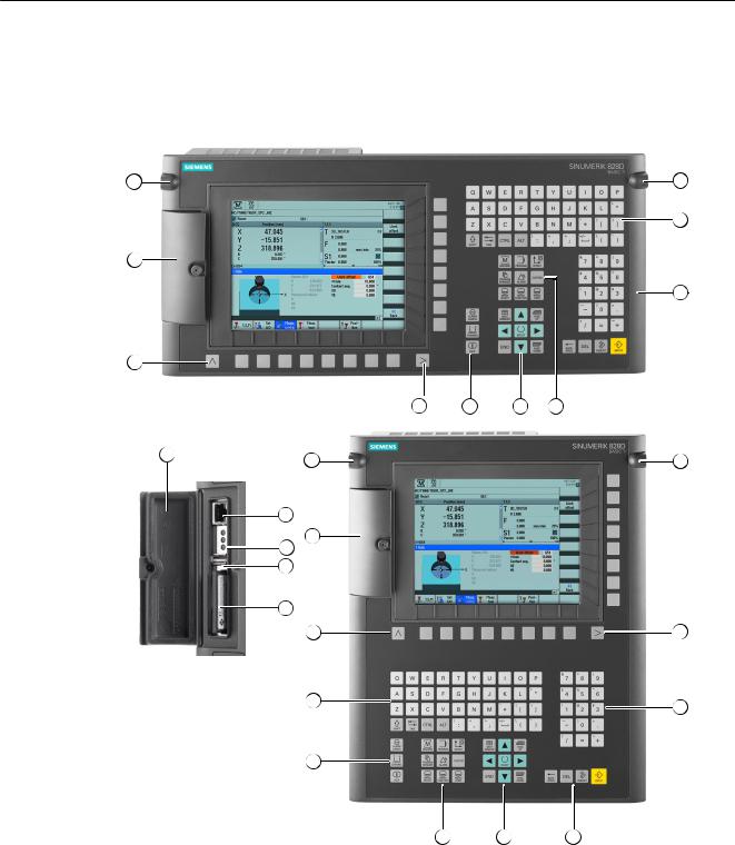
Front side of the PPU 24x.3 BASIC
PPU |
15 |
Manual, 01/2014, 6FC5397-2DP40-3BA3 |

System description
2.2 PPU version 24x.3 BASIC
Front cover Menu back key
Alphabetic key group Control key group Hotkey group Cursor key group Numerical block Menu forward key
3/8" threads for additional components X127 Ethernet (service socket)
Status LED: RDY, NC, CF X125 USB interface
Slot for CompactFlash card with user data
Figure 2-1 System versions
16 |
PPU |
Manual, 01/2014, 6FC5397-2DP40-3BA3 |
System description
2.2 PPU version 24x.3 BASIC
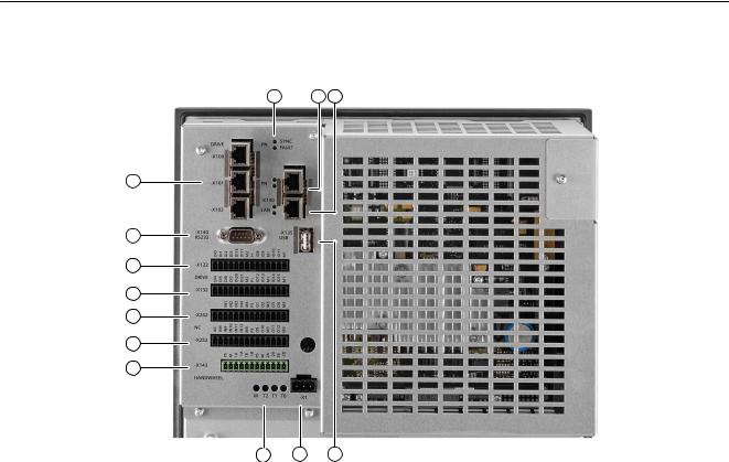
Rear side of the PPU 24x.3 BASIC
|
X122, X132 |
Digital inputs/outputs, drive |
|
X242, X252 |
Digital inputs/outputs for NC; controller of the analog spindle (X252) |
|
X143 |
Handwheels |
|
M, T2, T1, T0 |
Measuring sockets |
|
X1 |
Power supply |
|
X135 |
USB interface: For service purposes only |
|
X130 |
Ethernet LAN |
|
PN |
PLC I/O Interface |
|
SYNC, FAULT |
Status LEDs |
X100, X101, X102 DRIVE-CLiQ interfaces
|
X140 |
Serial interface RS232 |
Figure 2-2 Interfaces at the rear
PPU |
17 |
Manual, 01/2014, 6FC5397-2DP40-3BA3 |

System description
2.3 PPU versions 26x.3 and 28x.3
2.3PPU versions 26x.3 and 28x.3
Front of the PPU versions 26x.3 and 28x.3
18 |
PPU |
Manual, 01/2014, 6FC5397-2DP40-3BA3 |

System description
2.3 PPU versions 26x.3 and 28x.3
Front cover Menu back key
Alphabetic key group Control key group Hotkey group Cursor key group Numerical block Menu forward key
3/8" threads for additional components Front cover
X127 Ethernet (service socket) Status LED: RDY, NC, CF
X125 USB interface
Slot for CompactFlash card with user data
Figure 2-3 System versions
PPU |
19 |
Manual, 01/2014, 6FC5397-2DP40-3BA3 |
System description
2.3 PPU versions 26x.3 and 28x.3
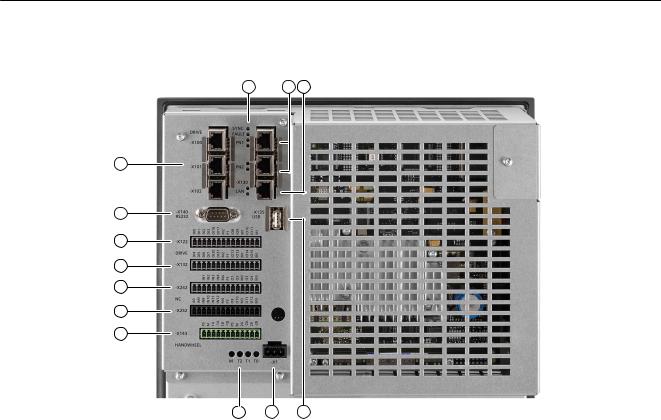
Rear of the PPU versions 26x.3 and 28x.3
X122, X132 |
Digital inputs/outputs, drive |
X242, X252 |
Digital inputs/outputs for NC; controller of the analog spindle (X252) |
X143 |
Handwheels |
M, T2, T1, T0 |
Measuring sockets |
X1 |
Power supply |
X135 |
USB interface: For service purposes only |
X130 |
Ethernet LAN |
PN 1, PN 2 |
PLC I/O Interface |
SYNC, FAULT |
Status LEDs |
X100, X101, X102 |
DRIVE-CLiQ interfaces |
X140 |
Serial interface RS232 |
Figure 2-4 Interfaces at the rear of the PPU
20 |
PPU |
Manual, 01/2014, 6FC5397-2DP40-3BA3 |
System description
2.4 Operator controls and display elements
2.4Operator controls and display elements
TFT color display
The TFT color display has a diagonal size of 10.4" (PPU 26x.3/28x.3) or 8.4" (PPU 24x.3). The resolution is 800 x 600 pixels. The softkeys are arranged in an 8 + 8 layout; this makes the CNC easy to operate using only a very small number of menu levels.
Note
Pixel error acc. to DIN EN ISO 13406-2 Class II.
Keyboard
Several keys and key pads are installed on the operator panel front:
●The alphabetic key group contains the letters A ... Z and the space character for entering text.
●The numeric key group contains the digits 0 - 9, arithmetic/special characters and the decimal point for entering numeric characters and operators.
●The cursor key group is used to navigate on the screen.
●The control key group includes special functions.
●The area changeover displays the operating areas.
●The menu forward key allows the horizontal softkey bar to be extended in the same menu.
●The softkeys call up functions that are available on screen via a menu bar.
●The machine area key switches directly into the "Machine" operating area.
●The menu back key returns to the superordinate menu, one window is closed.
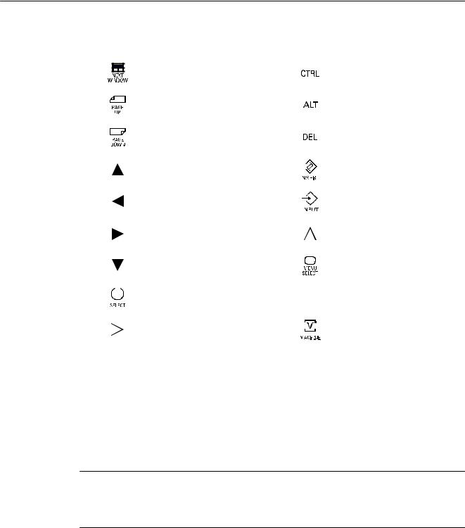
The keys used on the operator panel front along with the corresponding function keys on the PC keyboard are shown in the following overview:
|
Key |
|
Function corresponds to PC |
|
|
Key |
|
Function corresponds to PC |
|||||||
|
|
|
|
|
|
|
key function |
|
|
|
|
|
|
|
key function |
|
|
|
|
|
|
|
Esc |
|
|
|
|
|
|
|
End |
|
|
|
|
|
|
|
|
|
|
|
|||||
|
|
|
|
|
|
|
|
|
|
|
|
|
|
|
|
|
|
|
|
|
|
|
|
|
|
|
|
|
|
|
|
|
|
|
|
|
|
|
|
|
|
|
|
|
|
|
|
|
|
|
|
|
|
|
|
|
|
|
|
|
|
|
|
|
|
|
|
|
|
|
|
|
|
|
|
|
|
|
|
|
|
|
|
|
|
|
|
|
|
|
|
|
|
|
|
|
|
|
|
|
|
|
F11 |
|
|
|
|
|
|
|
Backspace |
|
|
|
|
|
|
|
|
|
|
|
|||||
|
|
|
|
|
|
|
|
|
|
|
|||||
|
|
|
|
|
|
|
|
|
|
|
|
|
|
|
|
|
|
|
|
|
|
|
|
|
|
|
|
|
|
|
|
|
|
|
|
|
|
|
|
|
|
|
|
|
|
|
|
|
|
|
|
|
|
|
|
|
|
|
|
|
|
|
|
|
|
|
|
|
|
|
F12 |
|
|
|
|
|
|
|
Tabulator |
|
|
|
|
|
|
|
|
|
|
|
|||||
|
|
|
|
|
|
|
|
|
|
|
|
|
|
|
|
|
|
|
|
|
|
|
|
|
|
|
|
|
|
|
|
|
|
|
|
|
|
|
|
|
|
|
|
|
|
|
|
|
|
|
|
|
|
|
|
|
|
|
|
|
|
|
|
|
|
|
|
|
|
|
|
|
|
|
|
|
|
|
|
|
|
|
|
|
|
|
Spaces |
|
|
|
|
|
|
|
(only for internal keyboard |
|
|
|
|
|
|
|
|
|
|
|
|||||
|
|
|
|
|
|
|
|
|
|
|
|
|
|
|
changeover) |
|
|
|
|
|
|
|
|
|
|
|
|
|
|
|
|
|
|
|
|
|
|
|
|
|
|
|
|
|
|
|
|
|
|
|
|
|
|
|
|
|
|
|
|
|
|
|
|
PPU |
21 |
Manual, 01/2014, 6FC5397-2DP40-3BA3 |
System description
2.5 Type plate
|
Key |
|
Function corresponds to PC |
|
|
|
Key |
|
Function corresponds to PC |
|||||||
|
|
|
|
|
|
|
|
key function |
|
|
|
|
|
|
|
key function |
|
|
|
|
|
|
|
|
Home |
|
|
|
|
|
|
|
CTRL key |
|
|
|
|
|
|
|
|
|
|
|
|
|||||
|
|
|
|
|
|
|
|
|
|
|
|
|
|
|
|
|
|
|
|
|
|
|
|
|
|
|
|
|
|
|
|
|
|
|
|
|
|
|
|
|
|
|
|
|
|
|
|
|
|
|
|
|
|
|
|
|
|
|
|
|
|
|
|
|
|
|
|
|
|
|
|
|
|
|
|
|
|
|
|
|
|
|
|
|
|
|
|
|
|
|
|
|
|
|
|
|
|
|
|
|
|
|
|
|
|
|
|
|
|
Page up |
|
|
|
|
|
|
|
ALT key |
|
|
|
|
|
|
|
|
|
|
|
|
|||||
|
|
|
|
|
|
|
|
|
|
|
|
|||||
|
|
|
|
|
|
|
|
|
|
|
|
|
|
|
|
|
|
|
|
|
|
|
|
|
|
|
|
|
|
|
|
|
|
|
|
|
|
|
|
|
|
|
|
|
|
|
|
|
|
|
|
|
|
|
|
|
|
|
Page down |
|
|
|
|
|
|
|
Delete |
|
|
|
|
|
|
|
|
|
|
|
|
|||||
|
|
|
|
|
|
|
|
|
|
|
|
|||||
|
|
|
|
|
|
|
|
|
|
|
|
|
|
|
|
|
|
|
|
|
|
|
|
|
|
|
|
|
|
|
|
|
|
|
|
|
|
|
|
|
|
|
|
|
|
|
|
|
|
|
|
|
|
|
|
|
|
|
|
|
|
|
|
|
|
|
|
|
|
|
|
|
|
|
|
|
|
|
|
|
|
|
|
|
|
|
|
|
|
|
|
|
Cursor up |
|
|
|
|
|
|
|
Insert |
|
|
|
|
|
|
|
|
|
|
|
|
|||||
|
|
|
|
|
|
|
|
|
|
|
|
|
|
|
|
|
|
|
|
|
|
|
|
|
|
|
|
|
|
|
|
|
|
|
|
|
|
|
|
|
|
|
|
|
|
|
|
|
|
|
|
|
|
|
|
|
|
|
|
|
|
|
|
|
|
|
|
|
|
|
|
|
|
|
|
Cursor left |
|
|
|
|
|
|
|
Enter |
|
|
|
|
|
|
|
|
|
|
|
|
|||||
|
|
|
|
|
|
|
|
|
|
|
|
|
|
|
|
|
|
|
|
|
|
|
|
|
|
|
|
|
|
|
|
|
|
|
|
|
|
|
|
|
|
|
|
|
|
|
|
|
|
|
|
|
|
|
|
|
|
|
|
|
|
|
|
|
|
|
|
|
|
|
|
|
|
|
|
Cursor right |
|
|
|
|
|
|
|
F9 |
|
|
|
|
|
|
|
|
|
|
|
|
|||||
|
|
|
|
|
|
|
|
|
|
|
|
|
|
|
|
|
|
|
|
|
|
|
|
|
|
|
|
|
|
|
|
|
|
|
|
|
|
|
|
|
|
Cursor down |
|
|
|
|
|
|
|
F10 |
|
|
|
|
|
|
|
|
|
|
|
|
|||||
|
|
|
|
|
|
|
|
|
|
|
|
|
|
|
|
|
|
|
|
|
|
|
|
|
|
|
|
|
|
|
|
|
|
|
|
|
|
|
|
|
|
|
|
|
|
|
|
|
|
|
|
|
|
|
|
|
|
|
|
|
|
|
|
|
|
|
|
|
|
|
|
|
|
|
|
|
|
|
|
|
||||
|
|
|
|
|
|
|
|
5 (in numeric key group) |
|
A ... Z |
|
A ... Z |
||||
|
|
|
|
|
|
|
||||||||||
|
|
|
|
|
|
|
|
|
|
|
|
|
|
|
|
|
|
|
|
|
|
|
|
|
|
|
|
|
|
|
|
|
|
|
|
|
|
|
|
|
|
<Shift> F9 |
|
|
|
|
|
|
|
<Shift> F10 |
|
|
|
|
|
|
|
|
|
|
|
|
|||||
|
|
|
|
|
|
|
|
|
|
|
|
|||||
|
|
|
|
|
|
|
|
|
|
|
|
|
|
|
|
|
|
|
|
|
|
|
|
|
|
|
|
|
|
|
|
|
|
|
|
|
|
|
|
|
|
|
|
|
|
|
|
|
|
|
|
|
|
|
|
|
|
|
|
|
|
|
|
|
|
|
|
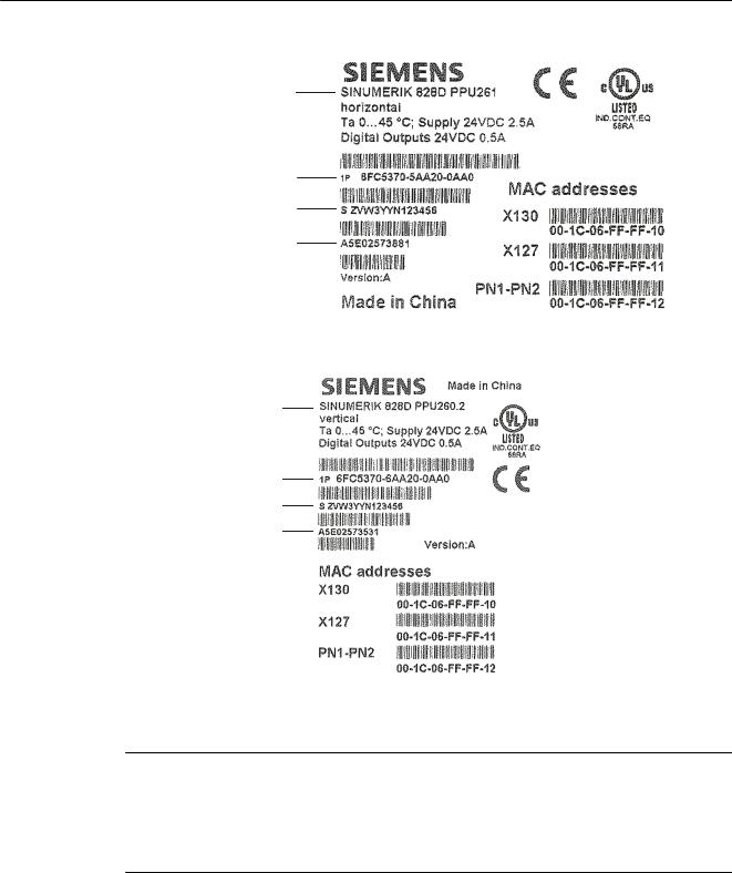
2.5Type plate
Type plates
The PPU type plate is located on the rear side.
Note
The contents of the individual type plate fields on the current controller may differ from those described in this Manual (e.g. updated product status, approvals and identifications not yet issued, etc.).
The following images display all the information required to uniquely identify a PPU.
22 |
PPU |
Manual, 01/2014, 6FC5397-2DP40-3BA3 |
System description
2.5 Type plate
&RPSRQ QW Q P |
|
$UWLFO QXP |
U |
|
|
||
|
||
6 UL O QXP |
U |
|
,' QXP |
U |
|
+: Y UVLRQ 
Figure 2-5 Horizontal PPU type plate
&RPSRQ QW Q P |
|
|
|
|
$UWLFO QXP |
U |
|
|
|
|
||||
6 UL O QXP |
U |
|||
,' QXP |
U |
|||
 +: Y UVLRQ
Figure 2-6 Vertical PPU type plate
Note
MAC addresses
The MAC addresses printed on the type plate of the PPU are required for configuring the PLC I/O Interface communications networks based on PROFINET and Industrial Ethernet.
There is a similar situation for the machine control panels and the I/O modules.
PPU |
23 |
Manual, 01/2014, 6FC5397-2DP40-3BA3 |
System description
2.6 System overview
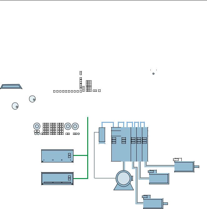
2.6System overview
Configuration with four axes (basic configuration)
The following configuration shows a typical example with SINAMICS S120 booksize:
&RPS Q\ QHWZRUN ,QGXVWUL O (W HUQHW
|
|
|
|
|
|
|
|
|
|
|
6,180(5,. ' |
|
|
|
|
|
|
|
|
|
|
|
|
|
|
|
||||
|
|
|
|
|
|
3HHU WR SHHU |
|
|
|
|
|
|
|
|
|
|
|
|
|
|
|
|
|
|
|
|
|
|||
|
|
|
|
|
|
|
|
|
|
|
|
|
|
|
|
|
|
|
|
|
|
|
|
|
|
|
||||
|
|
|
|
|
|
|
|
|
|
|
|
|
|
|
|
|
|
|
|
|
|
|
|
|
|
|
||||
|
|
|
|
|
|
|
|
|
|
|
|
|
|
|
|
|
|
|
|
|
|
|
|
|
|
|||||
|
|
|
|
|
|
|
|
|
|
|
|
|
|
|
|
|
|
|
|
|
|
|
|
|
|
|
|
|
|
|
|
|
|
|
|
|
|
|
|
|
|
|
|
|
|
|
|
|
|
|
|
|
|
|
|
|
|
|
|
|
|
|
|
|
|
|
|
|
|
|
|
|
|
|
|
|
|
|
|
|
|
|
|
|
|
1XOO PRGHP |
|
|
|
|
||
|
|
|
|
|
|
|
|
|
|
|
|
|
|
|
|
|
|
|
|
|
|
|
|
|
|
|
|
|||
|
|
|
|
|
|
|
|
|
|
|
|
|
|
|
|
|
|
|
|
|
|
|
|
F OH |
|
|
|
|
||
|
|
|
|
|
|
|
|
|
|
|
|
|
|
|
|
|
|
|
|
|
|
|
|
6,1$87 0' |
||||||
3* 3& |
|
|
|
|
|
|
|
|
|
|
|
|
|
|
|
|
|
|
|
|
|
|
|
|||||||
|
|
|
|
|
|
|
|
|
|
|
|
|
|
|
|
|
|
|
|
|
|
|
||||||||
|
|
|
|
|
|
|
|
|
|
|
|
|
|
|
|
|
|
|
|
|
|
|
|
|
|
|
||||
|
|
|
|
|
|
|
|
|
|
|
|
|
|
|
|
|
|
|
|
'5,9( &/L4 |
|
|
|
|
||||||
|
|
|
|
|
|
|
|
|
|
|
|
|
|
|
|
|
|
|
|
|
|
|
|
|||||||
|
|
|
|
|
|
|
|
|
|
|
|
|
|
|
|
|
|
|
|
|
|
|
|
|||||||
|
|
|
|
|
|
|
|
|
|
|
|
|
|
|
|
|
|
|
|
|
|
|
|
|
|
|
|
|
|
|
|
|
|
|
|
|
|
|
|
|
|
|
|
3/& , 2 LQWHUI FH VHG |
|
|
|
|
|
||||||||||||
|
|
[ QGZ HHO |
|
|
RQ 352),1(7 |
|
|
6,1$0,&6 6 |
|
|
|
|||||||||||||||||||
|
|
|
|
|
|
|
|
|
|
|
|
|
|
|
|
|
|
|
|
|
|
|
|
|
|
|
|
|||
|
|
|
|
|
|
|
|
|
|
|
|
|
|
|
|
|
|
|
|
|
|
|
|
|
|
|
|
|
|
|
|
|
|
|
|
|
|
|
|
|
|
|
|
|
|
|
|
|
|
|
|
|
|
|
|
|
|
|
|
|
|
|
|
|
|
|
|
|
|
|
|
|
|
|
|
|
|
|
|
|
|
|
|
|
|
|
|
|
|
|
|
|
|
|
|
|
|
|
|
|
|
|
|
|
|
|
|
|
|
|
|
|
|
|
|
|
|
|
|
|
|
|
|
|
|
|
|
|
|
|
|
|
|
|
|
|
|
|
|
|
|
|
|
|
|
|
|
|
|
|
|
|
|
|
0&3 31
60&
|
|
|
|
|
|
|
6/0 |
600 |
600 |
600 |
600 |
|
|
|
|
|
|
|
|
|
|
|
|||||
|
|
|
|
|
|
|
|
|
|
|
|
|
|
|
|
|
|
|
|
|
|
|
|
|
|
|
|
33 ' 31
6\QF URQRXV  PRWRU
PRWRU
33 ' $ 31 |
|
6\QF URQRXV PRWRU |
|
$V\QF URQRXV PRWRU |
|
||
|
|||
|
|
6\QF URQRXV PRWRU
Figure 2-7 Configuration example 1: Basic configuration with four axes
24 |
PPU |
Manual, 01/2014, 6FC5397-2DP40-3BA3 |
System description
2.6 System overview
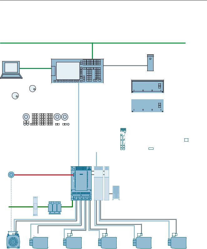
Configuration with S120 Combi and six axes
The following configuration shows the maximum expansion stage with SINAMICS S120 Combi:
&RPS Q\ QHWZRUN ,QGXVWUL O (WKHUQHW
6,180(5,. '
1XOO PRGHP F OH
3HHU WR SHHU
3* 3&
|
|
|
|
|
|
|
|
|
|
|
|
|
|
|
|
|
|
|
|
|
|
|
|
|
|
|
|
|
|
|
|
|
|
|
|
|
|
|
|
|
|
|
|
|
|
|
|
|
|
|
|
|
|
|
|
|
|
|
|
|
|
|
|
|
|
|
|
|
|
|
|
|
|
|
|
|
|
|
|
|
|
|
|
|
|
|
|
|
|
|
|
|
|
|
|
|
|
|
|
|
|
|
|
|
|
|
|
|
|
|
|
|
|
|
|
|
|
|
|
|
|
|
|
|
|
|
|
|
|
|
|
|
|
|
|
|
|
|
|
|
|
|
|
|
|
|
|
|
33 ' 31 |
|
|
|
|
|
|
|
|||
|
[ K QGZKHHO |
|
|
|
|
|
|
|
|
|
|
|
|
|
|
|
|
|
|
|
|
|
|
|
|
|
|||||
|
|
|
|
|
|
|
|
|
|
|
|
|
|
|
|
|
|
|
|
|
|
|
|
|
|
||||||
|
|
|
|
|
|
|
|
|
|
|
|
|
|
|
|
|
|
|
|
|
|
|
|
|
|
||||||
|
|
|
|
|
|
|
|
|
|
3/& , 2 LQWHUI FH VHG |
|
|
|
|
|
|
|
|
|
|
|
|
|||||||||
|
|
|
|
|
|
|
|
|
|
RQ 352),1(7 |
|
|
|
|
|
|
|
|
|
|
|
|
|||||||||
|
|
|
|
|
|
|
|
|
|
33 ' $ 31 |
|
|
|
|
|
||||||||||||||||
|
|
|
|
|
|
|
|
|
|
|
|
|
|
|
|
|
|
|
|
|
|
|
|
|
|||||||
|
|
|
|
|
|
|
|
|
|
70 ) |
|
|
|
|
|
|
|
|
|
|
|
|
|||||||||
|
|
|
|
|
|
|
|
|
|
|
|
|
|
|
|
|
|
|
|
'0& '0( |
|
8S WR ILYH |
|||||||||
|
|
|
|
|
|
|
|
|
|
|
|
|
|
|
|
|
|
|
|
|
|||||||||||
|
0&3 31 |
|
|
|
|
|
|
|
|
|
|
|
|
|
|
|
|
|
|||||||||||||
|
|
|
|
|
|
|
|
|
|
|
|
|
|
|
|
|
|
|
|
|
|
|
|
|
|
||||||
|
|
|
|
|
|
|
|
|
|
'5,9( &/L4 |
|
|
|
|
|
|
|
|
|
|
|
|
|
|
/LQH U VF OHV |
||||||
|
|
|
|
|
|
|
|
|
|
|
|
|
|
|
|
|
|
|
|
|
|
|
|
||||||||
|
|
|
|
|
|
|
|
|
|
|
|
|
|
|
|
|
|
|
|
|
|
|
|
|
|
|
|||||
|
|
|
|
|
|
|
|
|
|
|
|
|
|
|
|
|
|
|
|
|
|
|
|
|
|
|
|||||
|
|
|
|
|
|
|
|
|
|
|
|
|
|
|
|
|
|
|
|
|
|
|
|
|
|
|
|||||
|
|
|
|
|
|
|
|
|
|
|
|
|
|
|
|
|
|
|
|
|
|
|
|
|
|
|
|
|
|
|
|
|
|
|
|
|
|
|
|
|
|
|
|
|
|
|
|
|
|
|
|
|
|
|
|
|
|
|
|
|
|
|
|
|
|
|
|
|
|
|
|
|
|
|
|
|
|
|
|
|
|
|
|
|
|
|
|
|
|
|
|
|
|
|
|
|
|
|
|
|
|
|
|
|
|
|
|
|
|
|
|
|
|
|
|
|
|
|
|
|
|
|
|
|
|
|
|
|
|
6,1$0,&6 |
|
77/ VSLQGOH HQFRGHU |
|
6 &RP L |
♣ 'RX OH 0RWRU 0RGXOH %RRNVL]H &RPS FW |
|
|
3RZHU 0RGXOH |
♣ &RQWURO 6XSSO\ 0RGXOH |
|
|
|
|
|
|
|
♣ %U NLQJ 0 RGXOH %U NLQJ UHVLVWRU |
2SWLRQ |
O |
|
|
/LQH ILOWHU |
/LQH UH FWRU |
|
|
|
|
|
|
$& 9
0RWRU F OH
'5,9( &/L4
|
|
|
|
|
|
|
|
|
|
|
|
|
|
|
|
|
|
|
|
|
|
|
|
|
|
|
|
|
|
|
|
|
|
|
|
|
|
|
|
|
|
|
|
|
|
|
|
|
|
|
|
|
|
|
|
|
|
|
|
|
|
|
|
|
|
|
|
|
|
|
|
|
|
|
|
|
|
|
|
|
|
|
|
|
|
|
|
|
|
|
|
|
|
|
|
|
|
|
|
|
|
|
|
|
|
|
|
|
|
|
|
|
|
|
|
|
|
|
|
|
|
|
|
|
|
|
|
|
|
|
|
|
|
|
|
|
|
|
|
|
|
|
|
|
|
|
|
|
|
|
|
|
|
|
|
|
|
|
|
|
|
|
|
|
|
|
|
|
|
|
|
|
|
|
|
|
|
|
|
|
|
|
|
|
|
|
|
|
|
|
|
|
|
|
|
|
|
|
|
|
|
|
|
|
|
|
|
|
|
|
|
|
|
|
|
|
|
|
|
|
|
|
|
|
|
|
|
|
|
|
|
|
|
|
|
|
|
|
|
|
|
|
|
|
|
|
|
|
|
|
|
|
|
|
|
|
|
|
|
|
|
|
|
|
|
|
|
|
|
|
|
|
|
|
|
|
|
|
|
|
|
|
|
|
|
|
|
|
|
|
|
|
|
|
|
|
|
|
|
|
|
|
|
|
|
|
|
|
|
|
|
|
|
|
|
|
|
|
|
|
|
|
|
|
|
|
|
|
|
|
|
|
|
|
|
|
|
|
|
|
|
6SLQGOH PRWRU |
|
6HUYR PRWRU |
|
|
6HUYR PRWRU |
|
|
6HUYR PRWRU |
|
|
6HUYR PRWRU |
|
|
6HUYR PRWRU |
||||||||||||||||||||||||||||||||||||||||||
|
|
|
|
6XSSOHPHQW |
U\ |
|
|
|
|
|
|
|
|
|
|
|
|
|
|
|
|
|
|
|
|
|
|
|
|
|
|
|
|
|
|
|
|
|
||||||||||||||||||
|
|
|
|
VSLQGOH |
|
|
|
|
|
|
|
|
|
|
|
|
|
|
|
|
|
|
|
|
|
|
|
|
|
|
|
|
|
|
|
|
|
|
|
|
|
|
|
|
|
|
|
|
||||||||
Figure 2-8 Configuration example 2: Maximum expansion stage with six axes and with Safety Integrated
PPU |
25 |
Manual, 01/2014, 6FC5397-2DP40-3BA3 |

System description
2.7 Connectable components
2.7Connectable components
Component overview
The following components can be connected to the PPU:
●Machine Control Panel MCP 310C PN, MCP 483C PN
Contains the keys and switches required for the operation of a machine (turning or milling machine).
●Interface module MCP Interface PN
The MCP Interface PN module enables customer-specific machine control panels to be connected. Further, a 3rd handwheel can be connected via the module.
●Handwheels
A maximum of three handwheels can be connected.
●Mini handheld unit
A mini HHU can be integrated into the SINUMERIK 828D system using a connection kit.
●I/O modules PP 72/48D PN / PP 72/48D 2/2A PN
The modules are used to connect digital as well as analog inputs and outputs. To supply the module and the outputs, an external power supply unit (24 VDC) is required, which provides safety isolation from dangerous voltages.
●GSM modem
ConnectionofaSINAUTMD720-3GSMmodemforsendingandreceivingSMSmessages (Easy Message) via the serial RS232 interface.
●PN/PN coupler
A PN/PN coupler can be connected in order to link a SINUMERIK 828D to PROFINET networks.
●SENTRON PAC 3200/PAC 4200
The connection of a SENTRON PAC 3200 / PAC 4200 makes available functions for increasing the energy efficiency of machine tools.
SINAMICS S120 drive system
Only the SINAMICS S120 Line Modules and Motor Modules are used for drive control. Motor Modules can be used to connect servo motors as type 1FK7, 1FT7, and 1PH8 feed and main spindle motors. Type 1FW6 torque motors can also be connected.
See also
Connectable components (Page 93)
SINAMICS components (Page 86)
●Rules for permitted topologies (Page 53)
●Interface description (Page 67)
26 |
PPU |
Manual, 01/2014, 6FC5397-2DP40-3BA3 |

System description
2.8 Ordering data
2.8Ordering data
Ordering data of the components
SINUMERIK 828D is generally marketed in sales packages with drives, motors and accessories. For orders, please contact your local Siemens sales representative.
Table 2-1 |
Components |
|
|
|
|
|
|
Designation |
|
Article number |
|
Panel Processing Unit without system software |
|
||
● PPU 241.3 BASIC horizontal |
6FC5370-3AA30-0AA0 |
||
● PPU 240.3 BASIC vertical |
6FC5370-4AA30-0AA0 |
||
● |
PPU 261.3 horizontal |
6FC5370-5AA30-0AA0 |
|
● |
PPU 260.3 vertical |
6FC5370-6AA30-0AA0 |
|
● |
PPU 281.3 horizontal |
6FC5370-7AA30-0AA0 |
|
● |
PPU 280.3 vertical |
6FC5370-8AA30-0AA0 |
|
CompactFlash card with system software and license |
|
||
● For PPU 241.3 / PPU 240.3: Turning |
6FC5835-1GY40- YA0 |
||
● For PPU 241.3 / PPU 240.3: Milling |
6FC5835-2GY40- YA0 |
||
● For PPU 261.3 / PPU 260.3: Turning |
6FC5834-1GY40- YA0 |
||
● For PPU 261.3 / PPU 260.3: Milling |
6FC5834-2GY40- YA0 |
||
● For PPU 281.3 / PPU 280.3: Turning |
6FC5833-1GY40- YA0 |
||
● For PPU 281.3 / PPU 280.3: Milling |
6FC5833-2GY40- YA0 |
||
Axis extension: |
|
||
● Numeric Control Extension NX10.3 |
6SL3040-1NC00-0AA0 |
||
Machine control panels: |
|
||
● |
MCP 483C PN |
6FC5303-0AF22-0AA1 |
|
● |
MCP 310C PN |
6FC5303-0AF23-0AA1 |
|
Interface module |
|
||
● |
MCP Interface PN |
6FC5303-0AF03-0AA0 |
|
Mini handheld unit: |
|
||
● With spiral connection cable |
6FX2007-1AD03 |
||
● |
With straight cable |
6FX2007-1AD13 |
|
I/O modules: |
|
|
|
● PP 72/48D PN (digital) |
6FC5311-0AA00-0AA0 |
||
● PP 72/48D 2/2A PN (analog) |
6FC5311-0AA00-1AA0 |
||
PPU |
27 |
Manual, 01/2014, 6FC5397-2DP40-3BA3 |

System description
2.8 Ordering data
Spare parts
Table 2-2 |
Spare parts |
|
|
|
|
Designation |
|
Article number |
Set of tensioners (9 units) |
6FC5248-0AF14-0AA0 |
|
CompactFlash card (empty), 2 GB |
6FC5313-5AG00-0AA2 |
|
Front flap with fastening |
6FC5348-2AA00-0AA0 |
|
Accessories
Table 2-3 |
Accessories |
|
|
|
|
Designation |
|
Article number |
SENTRON PAC3200 Power Monitoring Device |
7KM2112-0BA00-3AA0 |
|
SENTRON PAC4200 Power Monitoring Device |
7KM4212-0BA00-3AA0 |
|
PROFINET Switched Ethernet expansion module |
7KM9300-0AE00-0AA0 |
|
SINAUT MD720-3 GSM/GPRS MODEM |
6NH9720-3AA00 |
|
SINAUT ANT 794-4MR ANTENNA |
6NH9860-1AA00 |
|
RS232 modem cable |
6NH7701-5AN |
|
SIMATIC DP PN/PN coupler |
6ES7158-3AD00-0XA0 |
|
Terminal strip converter, 50-pin |
6EP5406-5AA00 |
|
Cable set comprising: |
6EP5306-5BG00 |
|
● 6 m ribbon cable, 50-pin |
|
|
● 8 insulation displacement connectors, 50-pin |
|
|
IP20 PLC I/O interface connecting cable (corresponds to |
6FX2002-1DC00-... |
|
DRIVE-CLiQ signal cable) |
|
|
Blanking plates for the DRIVE-CLiQ interface |
6SL3066-4CA00-0AA0 |
|
USB flash drive, 8 GB |
6ES7648-0DC50-0AA0 |
|
CompactFlash card (empty as user memory), 8 GB |
6FC5313-6AG00-0AA0 |
|
Stabilized power supply SITOP lite 10 A |
6EP1334-1LB00 |
|
24 VDC, 1-phase |
|
|
Stabilized power supply SITOP smart 10 A |
6EP1334-2BA01 |
|
24 VDC, 1-phase |
|
|
Stabilized power supply PSU100S 20 A |
6EP1336-2BA10 |
|
24 VDC, 1-phase |
|
|
Stabilized power supply PSU300S 10 A |
6EP1434-2BA10 |
|
24 VDC, 3-phase |
|
|
Stabilized power supply PSU300S 20 A |
6EP1436-2BA10 |
|
24 VDC, 3-phase |
|
|
28 |
PPU |
Manual, 01/2014, 6FC5397-2DP40-3BA3 |

System description
2.9 CompactFlash Cards
2.9CompactFlash Cards
2.9.1CompactFlash card system
Overview
The PPU has two slots for CompactFlash cards:
●The slot for the user CompactFlash card is located at the front behind the front flap.
●The slot for the system CompactFlash card with the system software is at the rear.
CompactFlash card with system software
The system CompactFlash card is shipped in a bootable condition. It is not supplied with the PPU and must be ordered as a separate component.
The system CompactFlash card is essential for the operation of the PPU.
In addition to the technology-specific system software for SINUMERIK 828D and the firmware for SINAMICS, the system CompactFlash card also contains:
●Version information (serial number, version, type designation)
●Licensekey:AllowstheCompactFlashcardtobeinsertedintoanotherPPUwithouthaving to change the licenses.
Note the following when using a system CompactFlash card:
●SINUMERIK CNC supports the file systems FAT16 and FAT32 for CompactFlash cards. You may need to format the memory card if you want to use a memory card from another device or if you want to ensure the compatibility of the memory card with the SINUMERIK. However, formatting the memory card will permanently delete all data on it.
●Do not remove the memory card while it is being accessed. This can lead to damage of the memory card and the SINUMERIK as well as the data on the memory card.
●If you cannot use a memory card with the SINUMERIK, it is probably because the memory card is not formatted for the control system (e.g. Ext3 Linux file system), the memory card file system is faulty or it is the wrong type of memory card.
●Insertthememorycardcarefullyandtherightwayroundintothememorycardslot(observe indicatorssuchasarroworsimilar).Thiswayyouavoidmechanicaldamagetothememory card or the device.
PPU |
29 |
Manual, 01/2014, 6FC5397-2DP40-3BA3 |
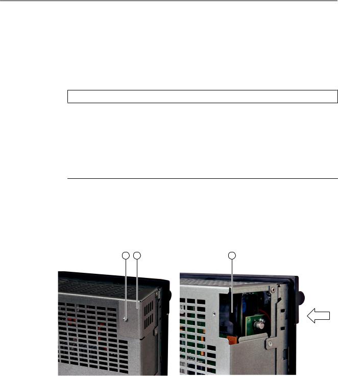
System description
2.9CompactFlash Cards
●Only use memory cards that have been approved by Siemens for use with SINUMERIK. Even though SINUMERIK follows general industry standards for memory cards, it is possible that memory cards from some manufacturers will not function perfectly in this device or are not completely compatible with it (you can obtain information on compatibility from the memory card manufacturer or supplier).
●For SINUMERIK 828D, only the memory card (2 GB) with order number 6FC5313-5AG00-0AA2 is permitted.
NOTICE
CompactFlash card system
●The CompactFlash card always comes formatted! You must not reformat it under any circumstances!
●To ensure that the system CompactFlash card functions properly, the card must not be repartitioned.
●In the event of a defect, the system software card must be replaced.
For information about restoring your system using an empty CompactFlash card, refer to the Service Manual.
2.9.2Inserting the system CompactFlash Card
Slot and mounting position
M3 screw Metal cover Slot
The CompactFlash card has an edge on the opposite side to the pins. This edge must always be on the right when inserting the card.
30 |
PPU |
Manual, 01/2014, 6FC5397-2DP40-3BA3 |
Loading...