


Dual Low Noise,
Audio Amplifier
The LM833 is a standard low±cost monolithic dual general±purpose operational amplifier employing Bipolar technology with innovative high±performance concepts for audio systems applications. With high frequency PNP transistors, the LM833 offers low voltage noise (4.5 nV/ Hz ), 15 MHz gain bandwidth product, 7.0 V/μs slew rate, 0.3 mV input offset voltage with 2.0 μV/°C temperature coefficient of input offset voltage. The LM833 output stage exhibits no deadband crossover distortion, large output voltage swing, excellent phase and gain margins, low open loop high frequency output impedance and symmetrical source/sink AC frequency response.
The LM833 is specified over the automotive temperature range and is available in the plastic DIP and SO±8 packages (P and D suffixes). For an improved performance dual/quad version, see the MC33079 family.
•Low Voltage Noise: 4.5 nV/ Hz
•High Gain Bandwidth Product: 15 MHz
•High Slew Rate: 7.0 V/μs
•Low Input Offset Voltage: 0.3 mV
•Low T.C. of Input Offset Voltage: 2.0 μV/°C
•Low Distortion: 0.002%
•Excellent Frequency Stability
•Dual Supply Operation
Order this document by LM833/D
LM833
DUAL OPERATIONAL
AMPLIFIER
SEMICONDUCTOR
TECHNICAL DATA
8
1
N SUFFIX
PLASTIC PACKAGE
CASE 626
8


1
D SUFFIX
PLASTIC PACKAGE
CASE 751 (SO±8)
MAXIMUM RATINGS
Rating |
Symbol |
Value |
Unit |
|
|
|
|
Supply Voltage (VCC to VEE) |
VS |
+36 |
V |
Input Differential Voltage Range (Note 1) |
VIDR |
30 |
V |
Input Voltage Range (Note 1) |
VIR |
±15 |
V |
Output Short Circuit Duration (Note 2) |
tSC |
Indefinite |
|
Operating Ambient Temperature Range |
TA |
±40 to +85 |
°C |
Operating Junction Temperature |
TJ |
+150 |
°C |
Storage Temperature |
Tstg |
±60 to +150 |
°C |
Maximum Power Dissipation (Notes 2 and 3) |
PD |
500 |
mW |
NOTES: 1. Either or both input voltages must not exceed the magnitude of VCC or VEE.
2.Power dissipation must be considered to ensure maximum junction temperature (TJ) is not exceeded (see power dissipation performance characteristic).
3.Maximum value at TA ≤ 85°C.
|
PIN CONNECTIONS |
|
||
Output 1 |
1 |
|
8 |
VCC |
|
2 |
1 |
7 |
Output 2 |
Inputs 1 |
|
|
|
|
|
3 |
|
6 |
|
|
|
2 |
|
Inputs 2 |
VEE |
4 |
|
5 |
|
|
|
(Top View) |
|
|
|
ORDERING INFORMATION |
||
|
|
Operating |
|
Device |
|
Temperature Range |
Package |
|
|
|
|
LM833N |
|
TA = ± 40° to +85°C |
Plastic DIP |
|
|
|
|
LM833D |
|
SO±8 |
|
|
|
||
|
|
|
|
Motorola, Inc. 1996 |
Rev 0 |
LM833
ELECTRICAL CHARACTERISTICS (VCC = +15 V, VEE = ±15 V, TA = 25°C, unless otherwise noted.)
Characteristic |
Symbol |
Min |
Typ |
Max |
Unit |
|||
|
|
|
|
|
|
|
|
|
Input Offset Voltage (RS = 10 Ω, VO = 0 V) |
VIO |
± |
0.3 |
5.0 |
mV |
|||
Average Temperature Coefficient of Input Offset Voltage |
VIO/ T |
± |
2.0 |
± |
μV/°C |
|||
RS = 10 Ω, VO = 0 V, TA = Tlow to Thigh |
|
|
|
|
|
|
|
|
Input Offset Current (VCM = 0 V, VO = 0 V) |
IIO |
± |
10 |
200 |
nA |
|
|
|
Input Bias Current (VCM = 0 V, VO = 0 V) |
IIB |
± |
300 |
1000 |
nA |
|
|
|
Common Mode Input Voltage Range |
VICR |
± |
+14 |
+12 |
V |
|
|
|
|
|
±12 |
±14 |
± |
|
|
|
|
|
|
|
|
|
|
|
|
|
Large Signal Voltage Gain (RL = 2.0 kΩ, VO = ±10 V |
AVOL |
90 |
110 |
± |
dB |
|
|
|
Output Voltage Swing: |
|
|
|
|
V |
|
|
|
RL = 2.0 kΩ, VID = 1.0 V |
VO+ |
10 |
13.7 |
± |
|
|
|
|
RL = 2.0 kΩ, VID = 1.0 V |
VO± |
± |
±14.1 |
±10 |
|
|
|
|
RL = 10 kΩ, VID = 1.0 V |
VO+ |
12 |
13.9 |
± |
|
|
|
|
RL = 10 kΩ, VID = 1.0 V |
VO± |
± |
±14.7 |
±12 |
|
|
|
|
Common Mode Rejection (Vin = ±12 V) |
CMR |
80 |
100 |
± |
dB |
|
|
|
Power Supply Rejection (VS = 15 V to 5.0 V, ±15 V to ±5.0 V) |
PSR |
80 |
115 |
± |
dB |
|
|
|
Power Supply Current (VO = 0 V, Both Amplifiers) |
ID |
± |
4.0 |
8.0 |
mA |
|||
AC ELECTRICAL CHARACTERISTICS (VCC = +15 V, VEE = ±15 V, TA = 25°C, unless otherwise noted.) |
|
|
|
|
|
|||
Characteristic |
Symbol |
Min |
Typ |
Max |
Unit |
|||
|
|
|
|
|
|
|
|
|
Slew Rate (Vin = ±10 V to +10 V, RL = 2.0 kΩ, AV = +1.0) |
SR |
5.0 |
7.0 |
± |
V/μs |
|||
Gain Bandwidth Product (f = 100 kHz) |
GBW |
10 |
15 |
± |
MHz |
|||
|
|
|
|
|
|
|
|
|
Unity Gain Frequency (Open Loop) |
fU |
± |
9.0 |
± |
MHz |
|||
Unity Gain Phase Margin (Open Loop) |
θm |
± |
60 |
± |
Deg |
|||
Equivalent Input Noise Voltage (RS = 100 Ω, f = 1.0 kHz) |
en |
± |
4.5 |
± |
|
|
|
|
|
||||||||
|
|
|
|
|
nV |
Hz |
||
Equivalent Input Noise Current (f = 1.0 kHz) |
in |
± |
0.5 |
± |
|
|
|
|
|
||||||||
|
|
|
|
|
pA |
Hz |
||
Power Bandwidth (VO = 27 Vpp, RL = 2.0 kΩ, THD ≤ 1.0%) |
BWP |
± |
120 |
± |
kHz |
|||
Distortion (RL = 2.0 kΩ, f = 20 Hz to 20 kHz, VO = 3.0 Vrms, AV = +1.0) |
THD |
± |
0.002 |
± |
% |
|
|
|
Channel Separation (f = 20 Hz to 20 kHz) |
CS |
± |
±120 |
± |
dB |
|
|
|
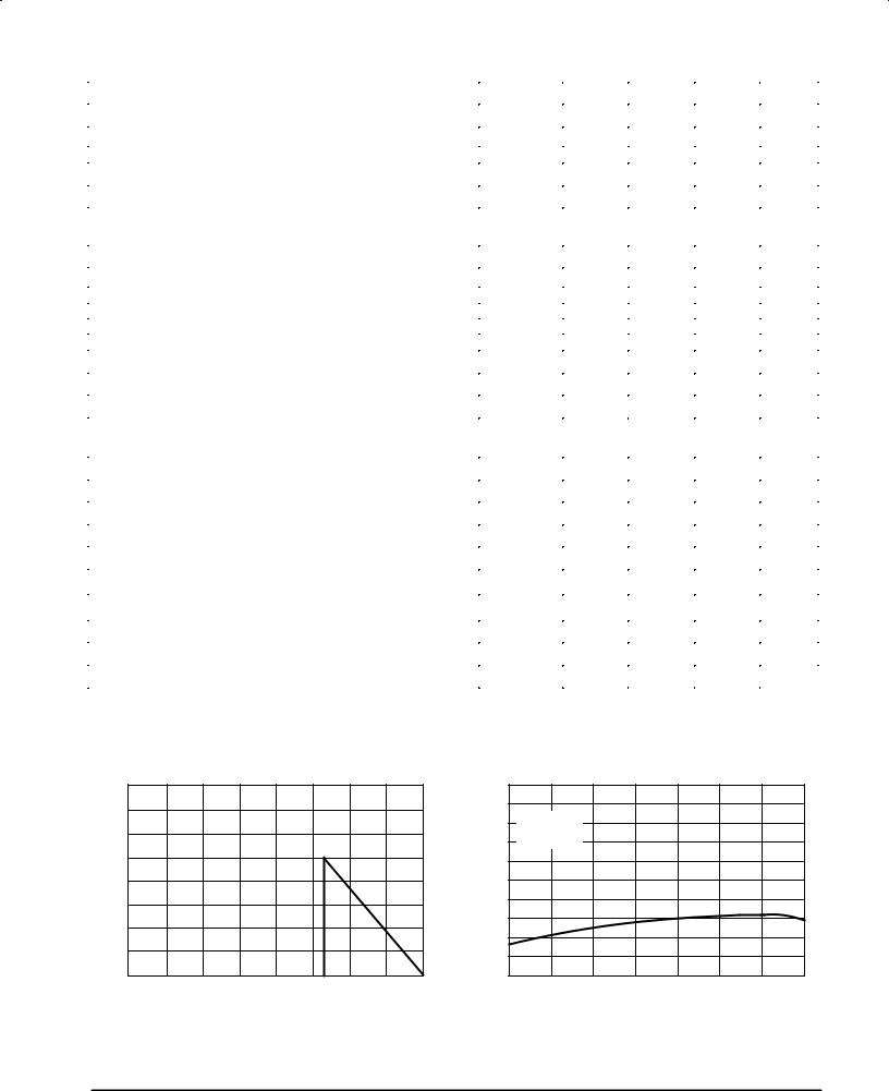
Figure 1. Maximum Power Dissipation |
|
|
|
|
|
|
|
|
versus Temperature |
Figure 2. Input Bias Current versus Temperature |
|||||||
(mW) |
800 |
|
|
|
|
DISSIPATIONPOWER |
600 |
|
|
|
CURRENTBIASINPUT(nA) |
|
|
|
|
|
|
MAXIMUM |
400 |
|
|
|
|
200 |
|
|
|
I |
|
|
|
|
|
|
, |
|
|
|
|
|
IB |
, |
|
|
|
|
|
D |
|
|
|
|
|
P |
0 |
|
|
|
|
|
0 |
50 |
100 |
150 |
|
|
±50 |
||||
|
|
TA, AMBIENT TEMPERATURE (°C) |
|
||
1000
800VCC = +15 V
VEE = ±15 V
VCM = 0 V
600
400
200
0 |
±25 |
0 |
25 |
50 |
75 |
100 |
125 |
±55 |
TA, AMBIENT TEMPERATURE (°C)
2 |
MOTOROLA ANALOG IC DEVICE DATA |

LM833
Figure 3. Input Bias Current versus
Supply Voltage
|
800 |
|
|
|
(nA) |
|
|
|
TA = 25°C |
CURRENT |
600 |
|
|
|
400 |
|
|
|
|
, INPUT BIAS |
|
|
|
|
200 |
|
|
|
|
IB |
|
|
|
|
I |
|
|
|
|
|
0 5.0 |
10 |
15 |
20 |
VCC, |VEE|, SUPPLY VOLTAGE (V)
Figure 4. Supply Current versus
Supply Voltage
|
10 |
|
VCC |
|
|
|
|
|
|
|
RL = ∞ |
|
|
|
|
I |
S |
|
|
|
(mA) |
8.0 |
|
|
TA = 25°C |
|
|
|
|
|
|
|||
CURRENT |
6.0 |
+ |
VO |
|
|
|
|
|
VEE |
|
|
|
|
, SUPPLY |
4.0 |
|
|
|
|
|
2.0 |
|
|
|
|
|
|
S |
|
|
|
|
|
|
I |
|
|
|
|
|
|
|
0 0 |
|
5.0 |
10 |
15 |
20 |
VCC, |VEE|, SUPPLY VOLTAGE (V)
AVOL, DC VOLTAGE GAIN (dB)
Figure 5. DC Voltage Gain |
Figure 6. DC Voltage Gain versus |
versus Temperature |
Supply Voltage |
110 |
|
|
|
|
|
VCC = +15 V |
|
110 |
|
|
|
|
|
|
|
|
|
|
|
|
RL = 2.0 kΩ |
|
|
|
|
|
|
|
|
VEE = ±15 V |
(dB) |
|
|
|
|
105 |
|
|
|
|
|
RL = 2.0 kΩ |
|
|
TA = 25°C |
|
|
|
|
|
|
|
|
|
|
|
|||
|
|
|
|
|
|
GAIN |
|
|
|
|
|
|
|
|
|
|
|
|
100 |
|
|
|
|
|
|
|
|
|
|
|
VOLTAGEDC |
|
|
|
|
100 |
|
|
|
|
|
|
90 |
|
|
|
|
|
|
|
|
|
|
|
|
|
|
|
|
95 |
|
|
|
|
|
|
, |
|
|
|
|
|
|
|
|
|
|
VOL |
|
|
|
|
|
|
|
|
|
|
|
|
|
|
|
|
|
|
|
|
|
|
|
|
A |
|
|
|
|
90 |
±25 |
0 |
25 |
50 |
75 |
100 |
125 |
80 |
10 |
15 |
20 |
±55 |
5.0 |
||||||||||
|
|
TA, AMBIENT TEMPERATURE (°C) |
|
|
VCC, |VEE|, SUPPLY VOLTAGE (V) |
|
|||||
Figure 7. Open Loop Voltage Gain and |
Figure 8. Gain Bandwidth Product |
|
|
|
Phase versus Frequency |
|
|
|
|
|
versus Temperature |
|
|
|||||||
(dB) |
120 |
|
|
|
|
|
|
|
0 |
GBW,GAIN BANDWIDTH PRODUCT (MHz) |
20 |
|
|
|
|
|
|
|
|
|
|
|
|
|
|
|
|
|
|
|
|
|
|
|
|
||
GAIN |
100 |
|
|
|
|
|
|
|
|
15 |
|
|
|
|
|
|
|
|
|
|
|
|
|
|
|
|
45 |
|
|
|
|
|
|
|
|||
VOLTAGE |
|
|
|
|
|
|
|
|
|
|
|
|
|
|
|
|||
80 |
|
|
|
|
|
|
|
|
|
|
|
|
|
|
|
|
||
|
|
|
|
|
|
|
Phase |
|
10 |
|
|
|
|
|
|
|
||
LOOP |
60 |
|
|
|
|
|
|
90 |
|
|
|
|
|
|
|
|||
|
|
|
|
|
|
|
|
|
|
|
|
|
|
|
||||
|
|
|
|
|
|
|
|
|
|
|
|
|
|
|
|
|
||
OPEN |
40 |
VCC = +15 V |
|
|
|
|
|
|
|
VCC = +15 V |
|
|
|
|
|
|||
|
VEE = ±15 V |
|
|
|
Gain |
|
135 |
5.0 |
VEE = ±15 V |
|
|
|
|
|
|
|||
, |
|
RL = 2.0 kΩ |
|
|
|
|
|
|
f = 100 kHz |
|
|
|
|
|
|
|||
VOL |
20 |
|
|
|
|
|
(DEGREES)PHASEEXCESS, |
|
|
|
|
|
|
|
||||
|
TA = 25°C |
|
|
|
|
|
|
|
|
|
|
|
|
|
||||
A |
0 |
|
|
|
|
|
|
|
0 |
|
|
|
|
|
|
|
||
|
|
|
|
|
|
|
|
180 |
|
|
|
|
|
|
|
|
||
|
1.0 |
10 |
100 |
1.0 k |
10 k |
100 k |
1.0 M |
10 M |
|
±55 |
±25 |
0 |
25 |
50 |
75 |
100 |
125 |
|
|
|
|
|
|
f, FREQUENCY (Hz) |
|
|
|
|
|
TA, AMBIENT TEMPERATURE (°C) |
|
|
|||||
MOTOROLA ANALOG IC DEVICE DATA |
3 |
|
 Loading...