


LM385Z-2.5
MOTOROLA LM385Z-2.5, LM385Z-1.2RP, LM385Z-1.2RA, LM385Z-1.2, LM385BD-1.2R2 Datasheet
...
SEMICONDUCTOR
TECHNICAL DATA
MICROPOWER VOLTAGE
REFERENCE DIODES
ORDERING INFORMATION
Order this document by LM285/D
Z SUFFIX
PLASTIC PACKAGE
CASE 29
D SUFFIX
PLASTIC PACKAGE
CASE 751
(SO–8)
(Bottom View)
132
8
7
6
5
Cathode
N.C.
N.C.
N.C.
4
3
2
Anode
N.C.
N.C.
1N.C.
N.C.
Cathode
Anode
–
+
LM385–1.2
1.235 V
3.3 k
1.5 V
Battery
Standard Application
Device
Operating
Temperature
Range
Tolerance
LM285D–1.2
LM285Z–1.2
TA = –40° to
+85°C
±1.0%
LM285D–2.5
LM285Z–2.5
LM385BD–1.2
LM385BZ–1.2
LM385D–1.2
LM385Z–1.2
LM385BD–2.5
LM385BZ–2.5
LM385D–2.5
LM385Z–2.5
Reverse
Break–
down
Voltage
1.235 V
±1.5%2.500 V
TA = 0° to
+70°C
±1.0%1.235 V
±2.0%1.235 V
±1.5%2.500 V
±3.0%2.500 V
1
MOTOROLA ANALOG IC DEVICE DATA
The LM285/LM385 series are micropower two–terminal bandgap voltage
regulator diodes. Designed to operate over a wide current range of 10 µA to
20 mA, these devices feature exceptionally low dynamic impedance, low
noise and stable operation over time and temperature. Tight voltage
tolerances are achieved by on–chip trimming. The large dynamic operating
range enables these devices to be used in applications with widely varying
supplies with excellent regulation. Extremely low operating current make
these devices ideal for micropower circuitry like portable instrumentation,
regulators and other analog circuitry where extended battery life is required.
The LM285/LM385 series are packaged in a low cost TO–226AA plastic
case and are available in two voltage versions of 1.235 and 2.500 V as
denoted by the device suffix (see Ordering Information table). The LM285 is
specified over a –40°C to +85°C temperature range while the LM385 is rated
from 0°C to +70°C.
The LM385 is also available in a surface mount plastic package in
voltages of 1.235 and 2.500 V.
• Operating Current from 10 µA to 20 mA
• 1.0%, 1.5%, 2.0% and 3.0% Initial Tolerance Grades
• Low Temperature Coefficient
• 1.0 Ω Dynamic Impedance
• Surface Mount Package Available
Representative Schematic Diagram
Open
for 1.235 V
10 k
Cathode
Anode
100 k500
Ω
600 k
600 k
425 k
74.3 k
8.45 k
600 k
360 k
Open
for 2.5 V
Motorola, Inc. 1996 Rev 2
LM285 LM385, B
2
MOTOROLA ANALOG IC DEVICE DATA
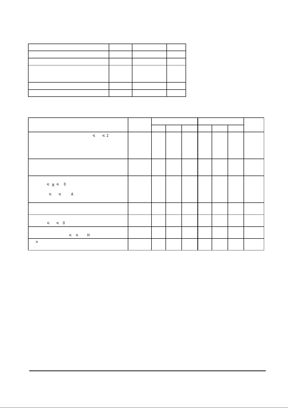
MAXIMUM RATINGS
(TA = 25°C, unless otherwise noted)
Rating
Symbol Value Unit
Reverse Current I
R
30 mA
Forward Current I
F
10 mA
Operating Ambient Temperature Range T
A
°C
LM285
LM385
– 40 to + 85
0 to +70
Operating Junction Temperature T
J
+ 150 °C
Storage Temperature Range T
stg
– 65 to + 150 °C
ELECTRICAL CHARACTERISTICS (T
A
= 25°C, unless otherwise noted)
LM285–1.2 LM385–1.2/LM385B–1.2
Characteristic Symbol Min Typ Max Min Typ Max Unit
Reverse Breakdown Voltage (I
Rmin
p IR p 20 mA) V
(BR)R
V
LM285–1.2/LM385B–1.2 1.223 1.235 1.247 1.223 1.235 1.247
TA = T
low
to T
high
(Note 1) 1.200 – 1.270 1.210 – 1.260
LM385–1.2 – – – 1.205 1.235 1.260
TA = T
low
to T
high
(Note 1) – – – 1.192 – 1.273
Minimum Operating Current I
Rmin
µA
TA = 25°C – 8.0 10 – 8.0 15
TA = T
low
to T
high
(Note 1) – – 20 – – 20
Reverse Breakdown Voltage Change with Current ∆V
(BR)R
mV
I
Rmin
p IR p 1.0 mA, TA = +25°C – – 1.0 – – 1.0
TA = T
low
to T
high
(Note 1) – – 1.5 – – 1.5
1.0 mA p IR p 20 mA, TA = +25°C – – 10 – – 20
TA = T
low
to T
high
(Note 1) – – 20 – – 25
Reverse Dynamic Impedance Z 0.6 – – 0.6 – W
IR = 100 µA, TA = +25°C
Average Temperature Coefficient ∆V
(BR)
/∆T – 80 – – 80 – ppm/°C
10 µA p IR p 20 mA, TA = T
low
to T
high
(Note 1)
Wideband Noise (RMS) n – 60 – – 60 – µV
IR = 100 µA, 10 Hz p f p 10 kHz
Long Term Stability S – 20 – – 20 – ppm/
IR = 100 µA, TA = +25°C ± 0.1°C kHR
LM285 LM385, B
3
MOTOROLA ANALOG IC DEVICE DATA
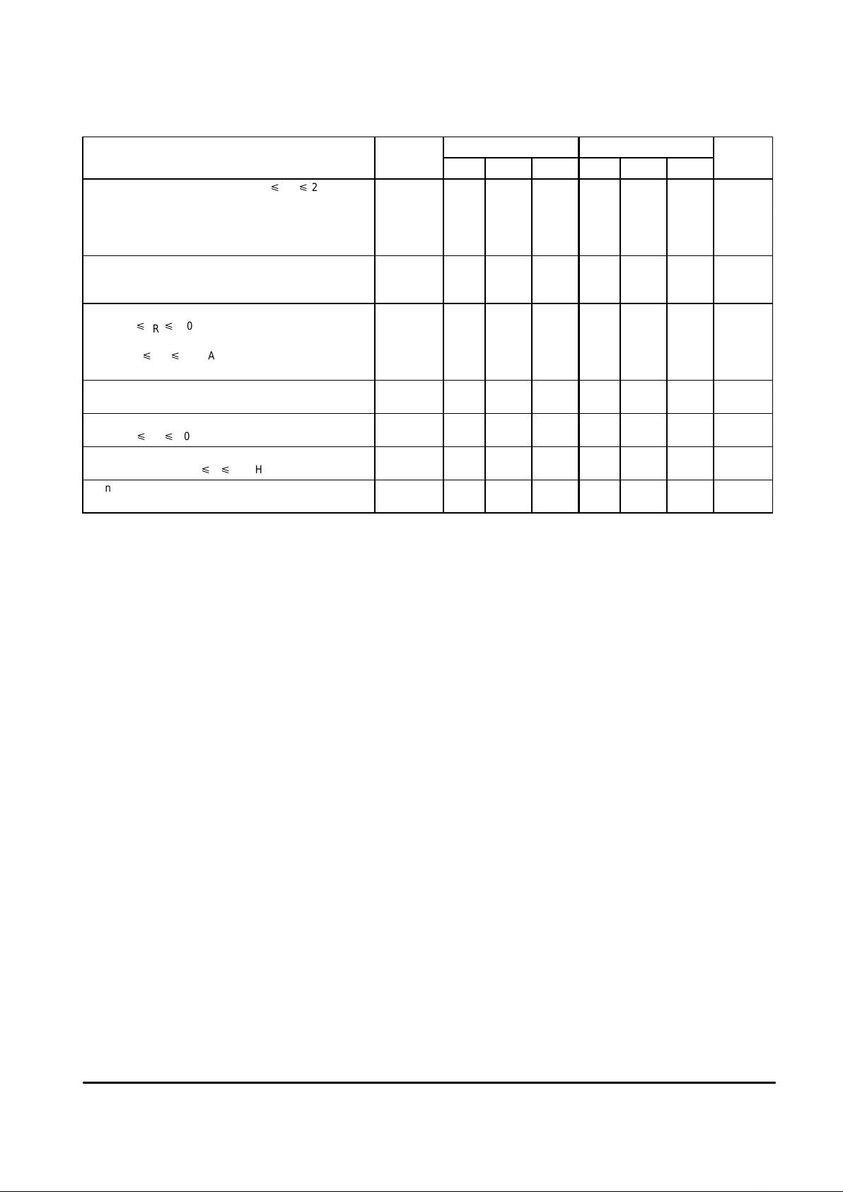
ELECTRICAL CHARACTERISTICS (T
A
= 25°C, unless otherwise noted)
LM285–2.5 LM385–2.5/LM385B–2.5
Characteristic Symbol Min Typ Max Min Typ Max Unit
Reverse Breakdown Voltage (I
Rmin
p IR p 20 mA) V
(BR)R
V
LM285–2.5/LM385B–2.5 2.462 2.5 2.538 2.462 2.5 2.538
TA = T
low
to T
high
(Note 1) 2.415 – 2.585 2.436 – 2.564
LM385–2.5 – – – 2.425 2.5 2.575
TA = T
low
to T
high
(Note 1) – – – 2.400 – 2.600
Minimum Operating Current I
Rmin
µA
TA = 25°C – 13 20 – 13 20
TA = T
low
to T
high
(Note 1) – – 30 – – 30
Reverse Breakdown Voltage Change with Current ∆V
(BR)R
mV
I
Rmin
p IR p 1.0 mA, TA = +25°C – – 1.0 – – 2.0
TA = T
low
to T
high
(Note 1) – – 1.5 – – 2.5
1.0 mA p IR p 20 mA, TA = +25°C – – 10 – – 20
TA = T
low
to T
high
(Note 1) – – 20 – – 25
Reverse Dynamic Impedance Z 0.6 – – 0.6 – W
IR = 100 µA, TA = +25°C
Average Temperature Coefficient ∆V
(BR)
/∆T – 80 – – 80 – ppm/°C
20 µA p IR p 20 mA, TA = T
low
to T
high
(Note 1)
Wideband Noise (RMS) n – 120 – – 120 – µV
IR = 100 µA, 10 Hz p f p 10 kHz
Long Term Stability S – 20 – – 20 – ppm/
IR = 100 µA, TA = +25°C ± 0.1°C kHR
NOTES: 1. T
low
= – 40°C for LM285–1.2, LM285–2.5 T
high
= +85°C for LM285–1.2, LM285–2.5
= 0°C for LM385–1.2, LM385B–1.2, LM385–2.5, LM385B–2.5 T
high
=+70°C for LM385–1.2, LM385B–1.2, LM385–2.5, LM385B–2.5
 Loading...