


INSTRUCTION MANUAL
MANUEL D'INSTRUCTION MANUAL DE INSTRUCCIONES
Cordless Slide Compound Miter Saw Scie Radiale Sans Fil
Sierra de Inglete Telescópica Inalámbrica
DLS713
011234
IMPORTANT: Read Before Using.
IMPORTANT: Lire avant usage.
IMPORTANTE: Leer antes de usar.

ENGLISH (Original instructions)
SPECIFICATIONS
Model |
DLS713 |
Blade diameter |
190 mm (7-1/2") |
Hole (arbor) diameter |
15.88 mm (5/8") |
Max. Miter angle |
Left 47°, Right 57° |
Max. Bevel angle |
Left 45°, Right 5° |
Max. Cutting capacities (H x W) with blade 190 mm (7-1/2") in diameter. |
|
|||
Miter angle |
|
Bevel angle |
|
|
45° (left) |
0° |
5° (right) |
||
|
||||
|
25 mm x 300 mm |
52 mm x 300 mm |
40 mm x 300 mm |
|
0° |
(1" x 11 - 3/4") |
(2 - 1/16" x 11 - 3/4") |
(1 - 9/16" x 11 - 3/4") |
|
----- |
* 60 mm x 265 mm (Note 1) |
----- |
||
|
||||
|
(2-3/8" x 10-3/8") |
|||
|
|
|
||
|
25 mm x 212 mm |
52 mm x 212 mm |
----- |
|
|
(1" x 8 - 3/8") |
(2 - 1/16" x 8 - 3/8") |
||
45° (left and right) |
|
|||
----- |
* 60 mm x 185 mm (Note 2) |
----- |
||
|
||||
|
(2-3/8" x 7-1/4") |
|||
|
|
|
||
|
----- |
52 mm x 163 mm |
----- |
|
|
(2 - 1/16" x 6 - 3/8") |
|||
57° (right) |
|
|
||
----- |
* 60 mm x 145 mm (Note 3) |
----- |
||
|
||||
|
(2-3/8" x 5-3/4") |
|||
|
|
|
||
No load speed (RPM) |
|
|
2,200 /min |
|
Dimensions (L x W x H) |
|
655 mm x 430 mm x 454 mm (25-3/4" x 17" x 17-7/8") |
||
Net weight (with battery BL1815N / BL1820 / BL1820B) |
|
12.1 kg (26.7 lbs) |
||
Net weight (with battery BL1830 / BL1830B / BL1840 / BL1840B / BL1850 / BL1850B / BL1860B) |
12.4 kg (27.3 lbs) |
|||
Rated voltage |
|
|
D.C. 18 V |
|
Standard battery cartridge |
BL1815N / BL1820 / BL1820B / BL1830 / BL1830B / BL1840 / BL1840B / BL1850 / BL1850B / BL1860B |
|||
(Note) |
|
|
|
|
* mark indicates that a wood facing with the following thickness is used.
1:When using a wood facing 20 mm thickness
2:When using a wood facing 15 mm thickness
3:When using a wood facing 10 mm thickness
•Due to our continuing program of research and development, the specifications herein are subject to change without notice.
•Specifications and battery cartridge may differ from country to country.
•Weight, with battery cartridge, according to EPTA-Procedure 01/2003
For Your Own Safety Read Instruction Manual
Before Operating Tool Save it for future reference
GENERAL SAFETY PRECAUTIONS
(For All Tools)
USA005-3 1. KNOW YOUR POWER TOOL. Read the owner's manual carefully. Learn the tool's applications and limitations, as well as the specific potential hazards peculiar to it.
2.KEEP GUARDS IN PLACE and in working order.
3.REMOVE ADJUSTING KEYS AND WRENCHES. Form habit of checking to see that keys and adjusting wrenches are removed from tool before turning it on.
4.KEEP WORK AREA CLEAN. Cluttered areas and benches invite accidents.
2

5.DO NOT USE IN DANGEROUS ENVIRONMENT. Do not use power tools in damp or wet locations, or expose them to rain. Keep work area well lighted. Do not use tool in presence of flammable liquids or gases.
6.KEEP CHILDREN AWAY. All visitors should be kept safe distance from work area.
7.MAKE WORKSHOP KID PROOF with padlocks, master switches, or by removing starter keys.
8.DO NOT FORCE TOOL. It will do the job better and safer at the rate for which it was designed.
9.USE RIGHT TOOL. Do not force tool or attachment to do a job for which it was not designed.
10.WEAR PROPER APPAREL. Do not wear loose clothing, gloves, neckties, rings, bracelets, or other jewelry which may get caught in moving parts. Nonslip footwear is recommended. Wear protective hair covering to contain long hair.
11.ALWAYS USE SAFETY GLASSES. Also use face or dust mask if cutting operation is dusty. Everyday eyeglasses only have impact resistant lenses, they are NOT safety glasses.
12.SECURE WORK. Use clamps or a vise to hold work when practical. It's safer than using your hand and it frees both hands to operate tool.
13.DO NOT OVERREACH. Keep proper footing and balance at all times.
14.MAINTAIN TOOLS WITH CARE. Keep tools sharp and clean for best and safest performance. Follow instructions for lubricating and changing accessories.
15.DISCONNECT BATTERY FROM TOOL before servicing; when changing accessories such as blades, bits, cutters, and the like.
20.DIRECTION OF FEED. Feed work into a blade or cutter against the direction of rotation of the blade or cutter only.
21.NEVER LEAVE TOOL RUNNING UNATTENDED. TURN POWER OFF. Do not leave tool until it comes to a complete stop.
22.Ensure the switch is in the off position before inserting battery cartridge. Inserting the battery cartridge into power tools that have the switch on invites accidents.
23.Recharge only with the charger specified by the manufacturer. A charger that is suitable for one type of battery cartridge may create a risk of fire when used with another battery cartridge.
24.Use power tools only with specifically designated battery cartridges. Use of any other battery cartridges may create a risk of injury and fire
25.When battery cartridge is not in use, keep it away from other metal objects like paper clips, coins, keys, nails, screws, or other small metal objects that can make a connection from one terminal to another. Shorting the battery terminals together may cause burns or a fire.
26.Under abusive conditions, liquid may be ejected from the battery; avoid contact. If contact accidentally occurs, flush with water. If liquid contacts eyes, additionally seek medical help. Liquid ejected from the battery may cause irritation or burns.
27.Disconnect battery cartridge from tool or place the switch in the locked or off position before making any adjustments, changing accessories, or storing the tool. Such preventive safety measures reduce the risk of starting the tool accidentally.
16.REDUCE THE RISK OF UNINTENTIONAL 28. Have your power tool serviced by a qualified
STARTING. Make sure switch is in off position before inserting battery.
17.USE RECOMMENDED ACCESSORIES. Consult the owner's manual for recommended accessories. The use of improper accessories may cause risk of injury to persons.
18.NEVER STAND ON TOOL. Serious injury could occur if the tool is tipped or if the cutting tool is unintentionally contacted.
19.CHECK DAMAGED PARTS. Before further use of the tool, a guard or other part that is damaged should be carefully checked to determine that it will operate properly and perform its intended function - check for alignment of moving parts, binding of moving parts, breakage of parts, mounting, and any other conditions that may affect its operation. A guard or other part that is damaged should be properly repaired or replaced.
repair person using only identical replacement parts. This will ensure that the safety of the power tool is maintained.
USB033-3
ADDITIONAL SAFETY RULES
DO NOT let comfort or familiarity with product (gained from repeated use) replace strict adherence to slide compound saw safety rules. If you use this tool unsafely or incorrectly, you can suffer serious personal injury.
1.Wear eye protection.
2.Keep hands out of path of saw blade. Avoid contact with any coasting blade. It can still cause severe injury.
3.Do not operate saw without guards in place. Check blade guard for proper closing before each use. Do not operate saw if blade guard does not move freely and close instantly. Never clamp or tie the blade guard into the open position.
3

4.Do not perform any operation freehand. The 21. Be sure that the blade does not contact the
workpiece must be secured firmly against the turn base and guide fence with a vise during all operations. Never use your hand to secure the workpiece.
5.Never reach around saw blade.
6.Turn off tool and wait for saw blade to stop before moving workpiece or changing settings.
7.Remove battery from tool before changing blade or servicing.
8.To reduce the risk of injury, return carriage to the full rear position after each crosscut operation.
turn base in the lowest position.
22.Hold the handle firmly. Be aware that the saw moves up or down slightly during start-up and stopping.
23.Make sure the blade is not contacting the workpiece before the switch is turned on.
24.Before using the tool on an actual workpiece, let it run for a while. Watch for vibration or wobbling that could indicate poor installation or a poorly balanced blade.
25.Wait until the blade attains full speed before cutting.
9.Always secure all moving portions before 26. Stop operation immediately if you notice
carrying the tool. |
anything abnormal. |
10.Stopper pin which locks the cutter head down 27. Do not attempt to lock the trigger in the "ON"
is for carrying and storage purposes only and not for any cutting operations.
11.Be aware that this tool is always in an operating condition, because it does not have to be plugged into an electrical outlet.
position.
28.Be alert at all times, especially during repetitive, monotonous operations. Do not be lulled into a false sense of security. Blades are extremely unforgiving.
12.Do not use the tool in the presence of 29. Always use accessories recommended in this
flammable liquids or gases. The electrical operation of the tool could create an explosion and fire when exposed to flammable liquids or gases.
13.Check the blade carefully for cracks or damage before operation. Replace cracked or damaged blade immediately. Gum and wood pitch hardened on blades slows saw and increases potential for kickback. Keep blade clean by first removing it from tool, then cleaning it with gum and pitch remover, hot water or kerosene. Never use gasoline to clean blade.
14.While making a slide cut, KICKBACK can occur. KICKBACK occurs when the blade binds in the workpiece during a cutting operation and the saw blade is driven rapidly towards the operator. Loss of control and serious personal injury can result. If blade begins to bind during a cutting operation, do not continue to cut and release switch immediately.
15.Use only flanges specified for this tool.
16.Be careful not to damage the arbor, flanges (especially the installing surface) or bolt. Damage to these parts could result in blade breakage.
17.Make sure that the turn base is properly secured so it will not move during operation. Use the holes in the base to fasten the saw to a stable work platform or bench. NEVER use tool where operator positioning would be awkward.
18.For your safety, remove the chips, small pieces, etc. from the table top before operation.
19.Avoid cutting nails. Inspect for and remove all nails from the workpiece before operation.
20.Make sure the shaft lock is released before the switch is turned on.
manual. Use of improper accessories such as abrasive wheels may cause an injury.
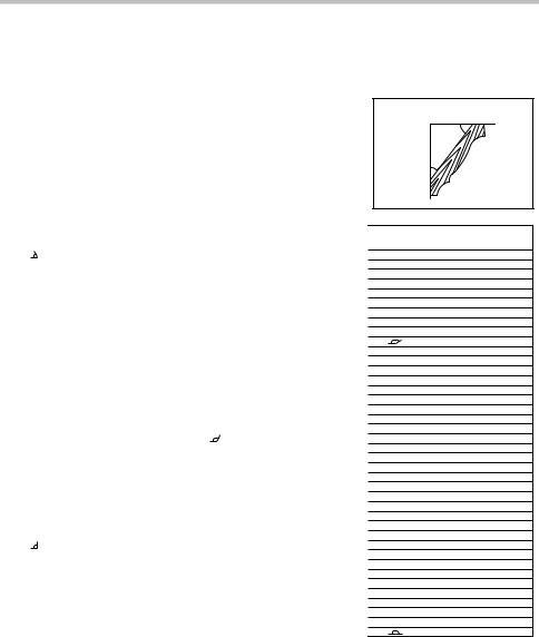
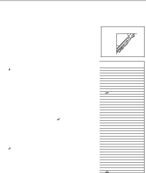
30.NEVER hold workpiece on right side of blade with left hand or vice versa. This is called cross-armed cutting and exposes user to risk of SERIOUS PERSONAL INJURY as shown in the figure. ALWAYS use vise to secure workpiece.
000030
31.NEVER stack workpieces on the table top to speed cutting operations. Cut only one piece at a time.
32.Some material contains chemicals which may be toxic. Take caution to prevent dust inhalation and skin contact. Follow material supplier safety data.
SAVE THESE INSTRUCTIONS.
 WARNING:
MISUSE or failure to follow the safety rules stated in this instruction manual may cause serious personal injury.
4
ENC007-10
IMPORTANT SAFETY INSTRUCTIONS
FOR BATTERY CARTRIDGE
1.Before using battery cartridge, read all instructions and cautionary markings on (1) battery charger, (2) battery, and (3) product using battery.
2.Do not disassemble battery cartridge.
3.If operating time has become excessively shorter, stop operating immediately. It may result in a risk of overheating, possible burns and even an explosion.
4.If electrolyte gets into your eyes, rinse them out with clear water and seek medical attention right away. It may result in loss of your eyesight.
5.Do not short the battery cartridge:
(1)Do not touch the terminals with any conductive material.
(2)Avoid storing battery cartridge in a container with other metal objects such as nails, coins, etc.
(3)Do not expose battery cartridge to water or rain. A battery short can cause a large current flow, overheating, possible burns and even a breakdown.
6.Do not store the tool and battery cartridge in
locations where the temperature may reach or exceed 50 C (122 F).
7.Do not incinerate the battery cartridge even if it is severely damaged or is completely worn out. The battery cartridge can explode in a fire.
8.Be careful not to drop or strike battery.
9.Do not use a damaged battery.
10.Follow your local regulations relating to disposal of battery.
SAVE THESE INSTRUCTIONS.
 CAUTION: Only use genuine Makita batteries.
Use of non-genuine Makita batteries, or batteries that have been altered, may result in the battery bursting causing fires, personal injury and damage. It will also void the Makita warranty for the Makita tool and charger.
Tips for maintaining maximum battery life
1.Charge the battery cartridge before completely discharged.
Always stop tool operation and charge the battery cartridge when you notice less tool power.
2.Never recharge a fully charged battery cartridge. Overcharging shortens the battery service life.
3.Charge the battery cartridge with room temperature at 10 C - 40 C (50 F - 104 F). Let a hot battery cartridge cool down before charging it.
4.Charge the battery cartridge if you do not use it for a long period (more than six months).
INSTALLATION
Bench mounting
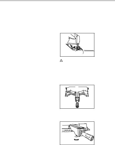
When the tool is shipped, the handle is locked in the lowered position by the stopper pin. Release the stopper pin by simultaneously applying a slight downward pressure on the handle and pulling the stopper pin.
1. Stopper pin
1

011300
WARNING:
•Ensure that the tool will not move on the supporting surface. Movement of the miter saw on the supporting surface while cutting may result
in loss of control and serious personal injury.
This tool should be bolted with two bolts to a level and stable surface using the bolt holes provided in the tool's base. This will help prevent tipping and possible injury.
1 |
1. Bolt |
011236
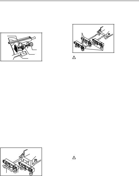
Turn the adjusting bolt clockwise or counterclockwise so that it comes into a contact with the floor surface to keep the tool stable.
1. Adjusting bolt
1
011237
5
FUNCTIONAL DESCRIPTION
 WARNING:
•Always be sure that the tool is switched off and the battery cartridge is removed before adjusting or checking the functions on the tool.
Failure to switch off and remove the battery cartridge may result in serious personal injury from accidental start-up.
Installing or removing battery cartridge
|
2 |
3 |
1 |
015772 |
|
 CAUTION:
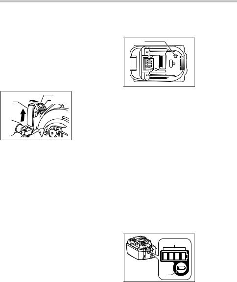
1.Red indicator
2.Button
3.Battery cartridge
•Always switch off the tool before installing or removing of the battery cartridge.
•Hold the tool and the battery cartridge firmly when installing or removing battery cartridge.
Failure to hold the tool and the battery cartridge firmly may cause them to slip off your hands and
result in damage to the tool and battery cartridge and a personal injury.
To remove the battery cartridge, slide it from the tool while sliding the button on the front of the cartridge.
To install the battery cartridge, align the tongue on the battery cartridge with the groove in the housing and slip it into place. Insert it all the way until it locks in place with a little click. If you can see the red indicator on the upper side of the button, it is not locked completely.
 CAUTION:
•Always install the battery cartridge fully until the red indicator cannot be seen. If not, it may accidentally fall out of the tool, causing injury to you or someone around you.
•Do not install the battery cartridge forcibly. If the cartridge does not slide in easily, it is not being inserted correctly.
Battery protection system (Lithium-ion battery with star marking)
1 |
1. Star marking |
012128 |
|
Lithium-ion batteries with a star marking are equipped with a protection system. This system automatically cuts off power to the tool to extend battery life.
The tool will automatically stop during operation if the tool and/or battery are placed under one of the following conditions:
•Overloaded:
The tool is operated in a manner that causes it to draw an abnormally high current.
In this situation, release the trigger switch on the tool and stop the application that caused the tool to become overloaded. Then pull the trigger switch again to restart.
If the tool does not start, the battery is overheated. In this situation, let the battery cool before pulling the trigger switch again.
•Low battery voltage:
The remaining battery capacity is too low and the tool will not operate. In this situation, remove and recharge the battery.
Indicating the remaining battery capacity
(Only for battery cartridges with "B" at the end of the model number.)
|
1. Indicator lamps |
1 |
2. CHECK button |
2 |
|
015676 |
|
Press the check button on the battery cartridge to indicate the remaining battery capacity. The indicator lamps light up for few seconds.
6

Indicator lamps
Remaining
capacity
Lighted |
Off |
Blinking |
75% to 100%
50% to 75%
25% to 50%
0% to 25%
Charge the
battery.
The battery may have malfunctioned.
015658
NOTE:
•Depending on the conditions of use and the ambient temperature, the indication may differ slightly from the actual capacity.
Blade guard
1. Blade guard
1
011238
When lowering the handle, the blade guard rises automatically. The guard is spring loaded so it returns to its original position when the cut is completed and the handle is raised.
WARNING:
•Never defeat or remove the blade guard or the spring which attaches to the guard. An exposed blade as a result of defeated guarding may result in serious personal injury during operation.
In the interest of your personal safety, always maintain the blade guard in good condition. Any irregular operation of the blade guard should be corrected immediately. Check to assure spring loaded return action of guard.
 WARNING:
•Never use the tool if the blade guard or spring are damaged, faulty or removed. Operation of the tool with a damaged, faulty or removed guard may result in serious personal injury.
If the see-through blade guard becomes dirty, or sawdust adheres to it in such a way that the blade and/or workpiece is no longer easily visible, remove the battery cartridge and clean the guard carefully with a damp cloth. Do not use solvents or any petroleum-based cleaners on the plastic guard because this may cause damage to the guard.
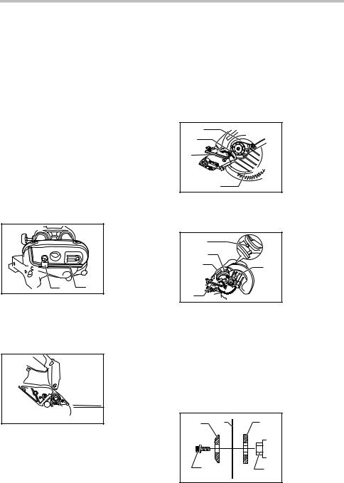
If the blade guard becomes dirty and needs to be cleaned for proper operation follow the steps below: With the tool switched off and the battery cartridge removed, use the supplied hex wrench to loosen the hex socket bolt holding the center cover. Loosen the hex socket bolt by turning it counterclockwise and raise the blade guard and center cover. With the blade guard so positioned, cleaning can be more completely and efficiently accomplished. When cleaning is complete reverse procedure above and secure bolt. Do not remove spring holding blade guard. If guard becomes damaged through age or UV light exposure, contact a Makita service center for a new guard. DO NOT
DEFEAT OR REMOVE GUARD.
1. Blade guard
 1
1
011239
Positioning kerf board
|
1 |
|
2 |
011240 |
|
1 |
2 |
3
4 |
5 |
001800
1.Thumb screw
2.Kerf board
1.Saw blade
2.Blade teeth
3.Kerf board
4.Left bevel cut
5.Straight cut
This tool is provided with the kerf boards in the turn base to minimize tearing on the exit side of a cut. The kerf boards are factory adjusted so that the saw blade does not contact the
7
kerf boards. Before use, adjust the kerf boards as follows: First, remove the battery cartridge. Loosen all the screws (2 each on left and right) securing the kerf boards. Re-tighten them only to the extent that the kerf boards can still be easily moved by hand. Lower the handle fully and push in the stopper pin to lock the handle in the lowered position. Loosen two clamp screws which secure the slide poles. Pull the carriage toward you fully. Adjust the kerf boards so that the kerf boards just contact the sides of the blade teeth. Tighten the front screws (do not tighten firmly). Push the carriage toward the guide fence fully and adjust the kerf boards so that the kerf boards just contact the sides of blade teeth. Tighten the rear screws (do not tighten firmly).
After adjusting the kerf boards, release the stopper pin and raise the handle. Then tighten all the screws securely.
NOTICE:
•After setting the bevel angle ensure that the kerf boards are adjusted properly. Correct adjustment of the kerf boards will help provide proper support of the workpiece minimizing workpiece tear out.
Maintaining maximum cutting capacity
1 |
1. Adjusting bolt |
|
2. Guide fence |
||
|
||
|
3. Turn base |
2
3
011265
|
1. Top surface of |
|
1 |
turn table |
|
2 |
2. Periphery of |
|
blade |
||
|
||
|
3. Guide fence |
3
005516
This tool is factory adjusted to provide the maximum cutting capacity for a 190 mm (7-1/2") saw blade. Remove the battery cartridge before any adjustment is attempted. When installing a new blade, always check the lower limit position of the blade and if necessary, adjust it as follows:
First, remove the battery cartridge. Push the carriage toward the guide fence fully and lower the handle completely. Use the hex wrench to turn the adjusting bolt until the periphery of the blade extends slightly below the top surface of the turn base at the point where the front face of the guide fence meets the top surface of the turn base.
With the battery cartridge removed, rotate the blade by hand while holding the handle all the way down to be sure that the blade does not contact any part of the lower base. Re-adjust slightly, if necessary.
 WARNING:
•After installing a new blade and with the battery cartridge removed, always be sure that the blade does not contact any part of the lower base when the handle is lowered completely. If a blade makes contact with the base it may cause kickback and result in serious personal injury.
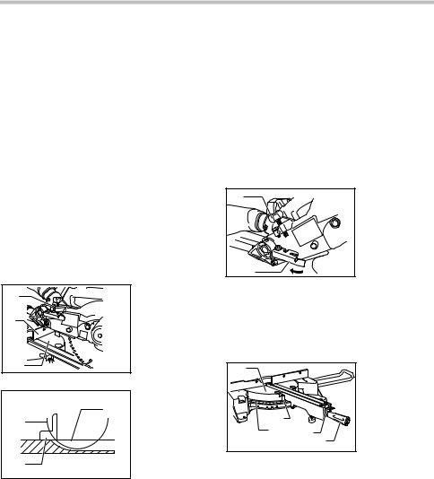
Stopper arm
1 |
1. Adjusting screw |
|
2. Stopper arm |
||
|
||
|
2 |
|
011241 |
|
The lower limit position of the blade can be easily adjusted with the stopper arm. To adjust it, move the stopper arm in the direction of the arrow as shown in the figure. Adjust the adjusting screw so that the blade stops at the desired position when lowering the handle fully.
Adjusting the miter angle
1 |
1. Turn base |
|
|
2. |
Pointer |
|
3. |
Miter scale |
|
4. |
Lock lever |
|
5. Grip |
|
3 |
2 |
|
4 |
|
|
|
5 |
|
011242 |
|
|
Loosen the grip by turning counterclockwise. Turn the turn base while pressing down the lock lever. When you have moved the grip to the position where the pointer points to the desired angle on the miter scale, securely tighten the grip clockwise.
 CAUTION:
•After changing the miter angle, always secure the
turn base by tightening the grip firmly.
NOTICE:
•When turning the turn base, be sure to raise the handle fully.
8
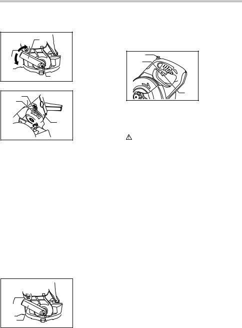
Adjusting the bevel angle
1 |
1. Lever |
|
2. Release button |
||
|
2 |
|
003930 |
|
|
1 |
1. Pointer |
|
2. Bevel scale |
||
2 |
||
3. Arm |
||
|
||
|
3 |
011301
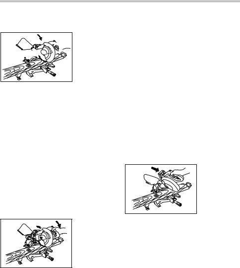
To adjust the bevel angle, loosen the lever at the rear of the tool counterclockwise.
Push the handle to the left to tilt the saw blade until the pointer points to the desired angle on the bevel scale. Then tighten the lever clockwise firmly to secure the arm.
To tilt the blade to the right, push the release button at the rear of the tool while tilting the blade slightly to the left after loosening the lever. With the release button depressed, tilt the saw blade to the right.
 CAUTION:
•After changing the bevel angle, always secure the arm by tightening the lever clockwise.
NOTICE:
•When tilting the saw blade be sure the handle is fully raised.
•When changing bevel angles, be sure to position the kerf boards appropriately as explained in the "Positioning kerf boards" section.
Adjusting the lever position
1. Lever
2. Screw
1 2
003932
The lever can be repositioned at every angle 30° when the lever does not provide full tightening.
Loosen and remove the screw that secures the lever at the rear of the tool. Remove the lever and install it again so that it is slightly above the level. Secure the lever with the screw firmly.
Switch action
1 |
1. |
Lock-off button |
|
2 |
2. |
Switch trigger |
|
3. |
Hole for padlock |
||
|
3
011243
To prevent the switch trigger from being accidentally pulled, a lock-off button is provided. To start the tool, press in the lock-off button and pull the switch trigger. Release the switch trigger to stop.
WARNING:
•Before installing the battery cartridge on the tool, always check to see that the switch trigger actuates properly and returns to the "OFF" position when released. Do not pull the switch
trigger hard without pressing in the lock-off button. This can cause switch breakage.
Operating a tool with a switch that does not actuate properly can lead to loss of control and serious personal injury.
A hole is provided in the switch trigger for insertion of a padlock to lock the tool off.
 WARNING:
•Do not use a lock with a shank or cable any smaller than 6.35 mm (1/4") in diameter. A smaller shank or cable may not properly lock the tool in the off position and unintentional operation may occur resulting in serious personal injury.
•NEVER use tool without a fully operative switch trigger. Any tool with an inoperative switch is HIGHLY DANGEROUS and must be repaired before further usage or serious personal injury may occur.
•For your safety, this tool is equipped with a lock-off button which prevents the tool from unintended starting. NEVER use the tool if it runs when you simply pull the switch trigger without pressing the lock-off button. A switch in need of repair may result in unintentional operation and serious personal injury. Return tool to a Makita service center for proper repairs BEFORE further usage.
•NEVER defeat the lock-off button by taping down or some other means. A switch with a defeated lock-off button may result in unintentional operation and serious personal injury.
9
Electric brake
This tool is equipped with an electric blade brake. If the tool consistently fails to quickly stop the blade after the switch trigger is released, have the tool serviced at a Makita service center.
 CAUTION:
•The blade brake system is not a substitute for the blade guard. Never use tool without a functioning blade guard. An unguarded blade may result in serious personal injury.
ASSEMBLY
 WARNING:
•Always be sure that the tool is switched off and the battery cartridge is removed before working on the tool. Failure to switch off and remove the battery cartridge may result in serious personal injury.
Hex wrench storage
1. Wrench holder
2. Hex wrench
1 2
012595
The hex wrench is stored as shown in the figure. When the hex wrench is needed it can be pulled out of the wrench holder. After using the hex wrench it can be stored by returning it to the wrench holder.
Installing or removing saw blade
1. Stopper pin
1

011300
 WARNING:
•Always be sure that the tool is switched off and the battery cartridge is removed before installing or removing the blade. Accidental start up of the tool may result in serious personal injury.
 CAUTION:
•Use only the Makita hex wrench provided to install
or remove the blade. Failure to do so may result in overtightening or insufficient tightening of the hex socket bolt. This could cause an injury.
Lock the handle in the raised position by pushing in the stopper pin.
To remove the blade, use the hex wrench to loosen the hex socket bolt holding the center cover by turning it counterclockwise. Raise the blade guard and center cover.
|
1 |
1. |
Center cover |
|
2. |
Hex socket bolt |
|
2 |
|
||
|
3. |
Hex wrench |
|
3 |
|
4. |
Safety cover |
|
|
|
4
012586
Press the shaft lock to lock the spindle and use the hex wrench to loosen the hex socket bolt clockwise. Then remove the hex socket bolt, outer flange and blade.
|
1 |
1. |
Shaft lock |
|
|
2. Arrow |
|||
|
2 |
3. |
Blade case |
|
3 |
|
4. |
Hex wrench |
|
5 |
5. |
Hex socket bolt |
||
|
||||
4
012587
NOTE:
•If the inner flange is removed be sure to install it on the spindle with its protrusion facing away from the blade. If the flange is installed incorrectly the flange will rub against the machine.
To install the blade, mount it carefully onto the spindle, making sure that the direction of the arrow on the surface of the blade matches the direction of the arrow on the blade case. Install the outer flange and hex socket bolt, and then use the hex wrench to tighten the hex socket bolt (left-handed) securely counterclockwise while pressing the shaft lock.
1 |
2 |
3 |
|
4 |
5 |
1.Outer flange
2.Saw blade
3.Inner flange
4.Hex socket bolt (left-handed)
5.Spindle
012717
10
1 |
2 |
3 |
4 |
1. |
Blade case |
|
|
|
|
2. Arrow |
|
|
|
|
|
3. Arrow |
|
|
|
|
|
4. |
Saw blade |
011244 |
|
|
|
|
|
Return the blade guard and center cover to its original position. Then tighten the hex socket bolt clockwise to secure the center cover. Release the handle from the raised position by pulling the stopper pin. Lower the handle to make sure that the blade guard moves properly. Make sure the shaft lock has released spindle before making cut.
Dust bag
1. Dust bag
1 2 2. Dust nozzle
3. Fastener
3
011304
To attach the fastener, align the top end of the fastener with the triangular mark on the dust bag.
The use of the dust bag makes cutting operations cleaner and dust collection easier. To attach the dust bag, fit it onto the dust nozzle.
When the dust bag is about half full, remove the dust bag from the tool and pull the fastener out. Empty the dust bag of its contents, tapping it lightly so as to remove particles adhering to the insides which might hamper further collection.
NOTE:
If you connect a vacuum cleaner to your saw, cleaner operations can be performed.
Securing workpiece
 WARNING:
•It is extremely important to always secure the workpiece correctly with the proper type of vise. Failure to do so may result in serious personal injury and cause damage to the tool and/or the workpiece.
•After a cutting operation do not raise the blade until it has come to a complete stop. The raising of a coasting blade may result in serious personal injury and damage to the workpiece.
•When cutting a workpiece that is longer than the support base of the saw, the material should be supported the entire length beyond the support base and at the same height to keep the material level. Proper workpiece support will help avoid blade pinch and possible kickback which may result in serious personal injury. Do not rely solely on the vertical vise and/or horizontal vise to secure the workpiece. Thin material tends to sag. Support workpiece over its entire length to avoid blade pinch and possible KICKBACK.
1 |
2 |
001549 |
|
Vertical vise
1.Support
2.Turn base
7 |
2 |
6 |
1. |
Vise arm |
|
2. |
Vise rod |
||
|
1 |
|||
|
|
3. |
Guide fence |
|
|
|
3 |
4. |
Holder |
|
|
5. |
Holder |
|
|
|
|
||
4 |
|
|
|
assembly |
|
|
6. |
Vise knob |
|
|
|
5 |
7. |
Screw |
|
|
|
|
|
002255 |
|
|
|
|
The vertical vise can be installed in two positions on either the left or right side of the guide fence or the holder assembly (optional accessory). Insert the vise rod into the hole in the guide fence or the holder assembly and tighten the screw to secure the vise rod.
Position the vise arm according to the thickness and shape of the workpiece and secure the vise arm by tightening the screw. If the screw to secure the vise arm contacts the guide fence, install the screw on the opposite side of vise arm. Make sure that no part of the tool contacts the vise when lowering the handle fully and pulling or pushing the carriage all the way. If some part contacts the vise, re-position the vise.
Press the workpiece flat against the guide fence and the turn base. Position the workpiece at the desired cutting position and secure it firmly by tightening the vise knob.
 WARNING:
•The workpiece must be secured firmly against the turn base and guide fence with the vise during all operations. If the workpiece is not properly secured against the fence the material
11
may move during the cutting operation causing possible damage to the blade, causing the material to be thrown and loss of control resulting in serious personal injury.
Horizontal vise (optional accessory)
3 |
1. Vise knob |
||
2. |
Projection |
||
|
|||
|
3. Vise shaft |
||
|
4. |
Base |
|
1
2
4
011305
The horizontal vise can be installed on the left side of the base. By turning the vise knob counterclockwise, the screw is released and the vise shaft can be moved rapidly in and out. By turning the vise knob clockwise, the screw remains secured. To grip the workpiece, turn the vise knob gently clockwise until the projection reaches its topmost position, then fasten securely. If the vise knob is forced in or pulled out while being turned clockwise, the projection may stop at an angle. In this case, turn the vise knob back counterclockwise until the screw is released, before turning again gently clockwise. The maximum width of the workpiece which can be secured by the horizontal vise is 120 mm (4-3/4").
 WARNING:
•Grip the workpiece only when the projection is at the topmost position. Failure to do so may result in insufficient securing of the workpiece. This could cause the workpiece to be thrown, cause damage to the blade or cause the loss of control, which can result in PERSONAL INJURY.
Holders and holder assembly (optional accessories)
|
1. Holder |
|
2. Holder |
|
assembly |
1 |
2 |
002247 |
|
The holders and the holder assembly can be installed on either side as a convenient means of supporting workpieces horizontally. Install them as shown in the figure. Then tighten the screws firmly to secure the holders and the holder assembly.
When cutting long workpieces, use the holder-rod assembly (optional accessory). It consists of two holder assemblies and two rods 12.
|
1. |
Holder |
|
2 |
|
assembly |
|
2. |
Rod 12 |
||
|
|||
|
1 |
|
|
002246 |
|
|
|
WARNING: |
|
|
•Always support a long workpiece so it is level with the top surface of the turn base for an accurate cut and to prevent dangerous loss of tool control. Proper workpiece support will help avoid blade pinch and possible kickback which may result in serious personal injury.
OPERATION
NOTICE:
•Before use, be sure to release the handle from the lowered position by pulling the stopper pin.
•Do not apply excessive pressure on the handle when cutting. Too much force may result in overload of the motor and/or decreased cutting efficiency. Push down handle with only as much force as is necessary for smooth cutting and without significant decrease in blade speed.
•Gently press down the handle to perform the cut. If the handle is pressed down with force or if lateral force is applied, the blade will vibrate and leave a mark (saw mark) in the workpiece and the precision of the cut will be impaired.
•During a slide cut, gently push the carriage toward the guide fence without stopping. If the carriage movement is stopped during the cut, a mark will be left in the workpiece and the precision of the cut will be impaired.
WARNING:
•Make sure the blade is not contacting the
workpiece, etc. before the switch is turned on.
Turning the tool on with the blade in contact with the workpiece may result in kickback and serious personal injury.
12
1.Press cutting (cutting small workpieces)
1. Clamp screw
1

011248
Workpieces up to 52 mm (2-1/16") high and 97 mm (3-13/16") wide can be cut in the following manner. Push the carriage toward the guide fence fully and tighten two clamp screws which secure the slide poles clockwise to secure the carriage. Secure the workpiece with the proper type of vise. Switch on the tool without the blade making any contact and wait until the blade attains full speed before lowering. Then gently lower the handle to the fully lowered position to cut the workpiece. When the cut is completed, switch off the tool and WAIT UNTIL THE BLADE HAS COME TO A COMPLETE STOP before returning the blade to its fully elevated position.
 WARNING:
•Firmly tighten two clamping screws which secure the slide poles clockwise so that the carriage will not move during operation. Insufficient tightening of the locking screw may cause possible kickback which may result in serious personal injury.
2.Slide (push) cutting (cutting wide workpieces)
011245 |
Loosen two clamp screws which secure the slide poles counterclockwise so that the carriage can slide freely. Secure the workpiece with the proper type of vise. Pull the carriage toward you fully. Switch on the tool without the blade making any contact and wait until the blade attains full speed. Press the handle down and PUSH THE CARRIAGE TOWARD THE GUIDE FENCE AND THROUGH THE WORKPIECE. When the cut is completed, switch off the tool and WAIT UNTIL THE BLADE HAS COME TO A COMPLETE STOP before returning the blade to its fully elevated position.
 WARNING:
•Whenever performing a slide cut, first pull the carriage full towards you and press the handle all the way down, then push the carriage toward the guide fence. Never start the cut with the carriage not pulled fully toward you. If you perform the slide cut without the carriage pulled fully toward you unexpected kickback may occur and serious personal injury may result.
•Never attempt to perform a slide cut by pulling the carriage towards you. Pulling the carriage towards you while cutting may cause unexpected kickback resulting in possible serious personal injury.
•Never perform the slide cut with the handle locked in the lowered position.
•Never loosen the knob which secures the carriage while the blade is rotating. A loose carriage while cutting may cause unexpected kickback resulting in possible in serious personal injury.
3.Miter cutting
Refer to the previously covered "Adjusting the miter angle".
4.Bevel cut
011246 |
Loosen the lever and tilt the saw blade to set the bevel angle (Refer to the previously covered "Adjusting the bevel angle"). Be sure to retighten the lever firmly to secure the selected bevel angle safely. Secure the workpiece with a vise. Make sure the carriage is pulled all the way back toward the operator. Switch on the tool without the blade making any contact and wait until the blade attains full speed. Then gently lower the handle to the fully lowered position while applying pressure in parallel with the blade and PUSH THE CARRIAGE TOWARD THE GUIDE FENCE TO CUT THE WORKPIECE. When the cut is completed, switch off the tool and WAIT UNTIL THE BLADE HAS COME TO A COMPLETE STOP before returning the blade to its fully elevated position.
 WARNING:
•After setting the blade for a bevel cut, before operating the tool ensure that the carriage and blade will have free travel throughout the entire
13
range of the intended cut. Interruption of the carriage or blade travel during the cutting operation may result in kickback and serious personal injury.
•While making a bevel cut keep hands out of the path of the blade. The angle of the blade may confuse the operator as to the actual blade path while cutting and contact with the blade will result in serious personal injury.
•The blade should not be raised until it has come to a complete stop. During a bevel cut the piece cut off may come to rest against the blade. If the blade is raised while it is rotating the cut-off piece maybe ejected by the blade causing the material to fragment which may result in serious personal injury.
NOTICE:
•When pressing down the handle, apply pressure in parallel with the blade. If a force is applied perpendicularly to the turn base or if the pressure direction is changed during a cut, the precision of the cut will be impaired.
5.Compound cutting
Compound cutting is the process in which a bevel angle is made at the same time in which a miter angle is being cut on a workpiece. Compound cutting can be performed at the angle shown in the table.
Miter angle |
Bevel angle |
|
Left and Right 45 |
Left 0 |
- 45 |
Right 50 |
Left 0 |
- 40 |
Right 55 |
Left 0 |
- 30 |
Right 57 |
Left 0 |
- 25 |
006393
When performing compound cutting, refer to "Press cutting", "Slide cutting", "Miter cutting" and "Bevel cut" explanations.
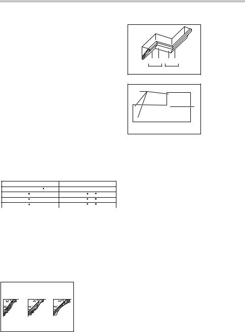
6.Cutting crown and cove moldings
Crown and cove moldings can be cut on a compound miter saw with the moldings laid flat on the turn base. There are two common types of crown moldings and one type of cove moldings; 52/38° wall angle crown molding, 45° wall angle crown molding and 45° wall angle cove molding. See illustrations.
1. 52/38 type crown molding
2. 45 type crown molding
3. 45 type cove molding
1 |
2 |
3 |
001555
There are crown and cove molding joints which are made to fit "Inside" 90° corners ((1) and (2) in Fig. A) and "Outside" 90° corners ((3) and (4) in Fig. A).
|
(1) (2) |
(3) (4) |
|
Fig.A |
1 |
2 |
|
001556 |
|
|
|
1 |
|
(2) |
(1) |
|
|
(1) |
(2) |
(2) |
|
(4) |
2 |
|
(3) |
||
(1) |
|
|
|
(2) |
|
|
(1) |
(1) |
|
|
(2) |
001557 |
|
|
|
1.Inside corner
2.Outside corner
1.Inside corner
2.Outside corner
Measuring
Measure the wall length and adjust workpiece on table to cut wall contact edge to desired length. Always make sure that cut workpiece length at the back of the workpiece is the same as wall length. Adjust cut length for angle of cut. Always use several pieces for test cuts to check the saw angles.
When cutting crown and cove moldings, set the bevel angle and miter angle as indicated in the table (A) and position the moldings on the top surface of the saw base as indicated in the table (B).
In the case of left bevel cut
Table (A)
|
|
Molding |
Bevel angle |
Miter angle |
||
|
|
position in |
|
|
|
|
|
|
Fig. A |
52/38° type |
45° type |
52/38° type |
45° type |
|
|
|
|
|
|
|
|
For inside |
(1) |
|
|
Right 31.6° |
Right 35.3° |
|
corner |
(2) |
|
|
|
|
|
|
Left 33.9° |
Left 30° |
Left 31.6° |
Left 35.3° |
|
|
For outside |
(3) |
||||
|
|
|
|
|
||
|
corner |
(4) |
|
|
Right 31.6° |
Right 35.3° |
|
|
|
|
|||
|
006361 |
|
|
|
|
|
Table (B)
|
|
Molding |
Molding edge against |
|
|
|
position in |
Finished piece |
|
|
|
guide fence |
||
|
|
Fig. A |
|
|
|
|
|
|
|
|
|
(1) |
Ceiling contact edge should |
Finished piece |
|
|
be against guide fence. |
||
|
|
will be on the |
||
|
For inside |
|
||
|
|
|
||
|
corner |
(2) |
|
Left side of |
|
|
Wall contact edge should be |
blade. |
|
|
|
|
|
|
|
For |
|
against guide fence. |
Finished piece |
|
(3) |
|
||
|
outside |
|
will be on the |
|
|
|
|
||
|
corner |
|
Ceiling contact edge should |
Right side of |
|
|
(4) |
blade. |
|
|
|
be against guide fence. |
||
|
|
|
|
|
|
|
|
|
|
|
006362 |
|
|
|
14

Example:
In the case of cutting 52/38° type crown molding for position (1) in Fig. A:
•Tilt and secure bevel angle setting to 33.9° LEFT.
•Adjust and secure miter angle setting to 31.6° RIGHT.
•Lay crown molding with its broad back (hidden) surface down on the turn base with its CEILING CONTACT EDGE against the guide fence on the saw.
•The finished piece to be used will always be on the LEFT side of the blade after the cut has been made.
In the case of right bevel cut
Table (A)
|
|
Molding |
Bevel angle |
Miter angle |
||
|
|
position in |
|
|
|
|
|
|
Fig. A |
52/38° type |
45° type |
52/38° type |
45° type |
|
|
|
|
|
|
|
|
For inside |
(1) |
|
|
Right 31.6° |
Right 35.3° |
|
corner |
(2) |
|
|
|
|
|
|
|
Right 33.9° |
Right 30° |
Left 31.6° |
Left 35.3° |
|
For outside |
(3) |
||||
|
|
|
|
|
||
|
corner |
(4) |
|
|
Right 31.6° |
Right 35.3° |
|
|
|
|
|
|
|
|
006363 |
|
|
|
|
|
Table (B)
|
|
Molding |
Molding edge against |
|
|
|
position in |
Finished piece |
|
|
|
guide fence |
||
|
|
Fig. A |
|
|
|
|
|
|
|
|
|
(1) |
Wall contact edge should be |
Finished piece |
|
|
against guide fence. |
will be on the |
|
|
For inside |
|
||
|
|
|
||
|
corner |
(2) |
|
Right side of |
|
|
Ceiling contact edge should |
blade. |
|
|
|
|
|
|
|
For |
|
be against guide fence. |
Finished piece |
|
(3) |
|
||
|
outside |
|
will be on the |
|
|
|
|
||
|
corner |
(4) |
Wall contact edge should be |
Left side of |
|
|
against guide fence. |
blade. |
|
|
|
|
|
|
|
006364 |
|
|
|
Example:
In the case of cutting 52/38° type crown molding for position (1) in Fig. A:
•Tilt and secure bevel angle setting to 33.9° RIGHT.
•Adjust and secure miter angle setting to 31.6° RIGHT.
•Lay crown molding with its broad back (hidden) surface down on the turn base with its WALL CONTACT EDGE against the guide fence on the saw.
•The finished piece to be used will always be on the RIGHT side of the blade after the cut has been made.
15
Compound Miter Saw
Miter and Bevel Angle Settings
Ceiling
|
|
|
|
|
|
|
|
Wall |
Wall to Crown Molding Angle: 52/38 degrees |
|
|
000031 |
|||||
|
|
|
|
|||||
|
|
|
|
|
|
|
|
|
Wall Angle |
Bevel Angle |
Miter Angle |
|
Wall Angle |
Bevel Angle |
Miter Angle |
|
Wall Angle |
(deg.) |
(deg.) |
(deg.) |
|
(deg.) |
(deg.) |
(deg.) |
|
(deg.) |
|
|
|
|
|
|
|
|
|
60 |
43.0 |
46.8 |
|
101 |
30.1 |
26.9 |
|
141 |
61 |
42.8 |
46.3 |
|
102 |
29.7 |
26.5 |
|
142 |
62 |
42.5 |
45.7 |
|
103 |
29.4 |
26.1 |
|
143 |
63 |
42.2 |
45.1 |
|
104 |
29.0 |
25.7 |
|
144 |
64 |
41.9 |
44.6 |
|
105 |
28.7 |
25.3 |
|
145 |
65 |
41.7 |
44.0 |
|
106 |
28.3 |
24.9 |
|
146 |
66 |
41.4 |
43.5 |
|
107 |
28.0 |
24.5 |
|
147 |
67 |
41.1 |
42.9 |
|
108 |
27.6 |
24.1 |
|
148 |
68 |
40.8 |
42.4 |
|
109 |
27.2 |
23.7 |
|
149 |
69 |
40.5 |
41.9 |
|
110 |
26.9 |
23.3 |
|
150 |
70 |
40.2 |
41.3 |
|
111 |
26.5 |
22.9 |
|
151 |
71 |
39.9 |
40.8 |
|
112 |
26.1 |
22.6 |
|
152 |
72 |
39.6 |
40.3 |
|
113 |
25.8 |
22.2 |
|
153 |
73 |
39.3 |
39.8 |
|
114 |
25.4 |
21.8 |
|
154 |
74 |
39.0 |
39.2 |
|
115 |
25.0 |
21.4 |
|
155 |
75 |
38.7 |
38.7 |
|
116 |
24.7 |
21.0 |
|
156 |
76 |
38.4 |
38.2 |
|
117 |
24.3 |
20.7 |
|
157 |
77 |
38.1 |
37.7 |
|
118 |
23.9 |
20.3 |
|
158 |
78 |
37.8 |
37.2 |
|
119 |
23.6 |
19.9 |
|
159 |
79 |
37.4 |
36.8 |
|
120 |
23.2 |
19.6 |
|
160 |
80 |
37.1 |
36.3 |
|
121 |
22.8 |
19.2 |
|
161 |
81 |
36.8 |
35.8 |
|
122 |
22.5 |
18.8 |
|
162 |
82 |
36.5 |
35.3 |
|
123 |
22.1 |
18.5 |
|
163 |
83 |
36.2 |
34.8 |
|
124 |
21.7 |
18.1 |
|
164 |
84 |
35.8 |
34.4 |
|
125 |
21.3 |
17.8 |
|
165 |
85 |
35.5 |
33.9 |
|
126 |
21.0 |
17.4 |
|
166 |
86 |
35.2 |
33.4 |
|
127 |
20.6 |
17.1 |
|
167 |
87 |
34.9 |
33.0 |
|
128 |
20.2 |
16.7 |
|
168 |
88 |
34.5 |
32.5 |
|
129 |
19.8 |
16.4 |
|
169 |
89 |
34.2 |
32.1 |
|
130 |
19.5 |
16.0 |
|
170 |
90 |
33.9 |
31.6 |
|
131 |
19.1 |
15.7 |
|
171 |
91 |
33.5 |
31.2 |
|
132 |
18.7 |
15.3 |
|
172 |
92 |
33.2 |
30.7 |
|
133 |
18.3 |
15.0 |
|
173 |
93 |
32.8 |
30.3 |
|
134 |
17.9 |
14.6 |
|
174 |
94 |
32.5 |
29.9 |
|
135 |
17.6 |
14.3 |
|
175 |
95 |
32.2 |
29.4 |
|
136 |
17.2 |
14.0 |
|
176 |
96 |
31.8 |
29.0 |
|
137 |
16.8 |
13.6 |
|
177 |
97 |
31.5 |
28.6 |
|
138 |
16.4 |
13.3 |
|
178 |
98 |
31.1 |
28.2 |
|
139 |
16.0 |
13.0 |
|
179 |
99 |
30.8 |
27.7 |
|
140 |
15.6 |
12.8 |
|
180 |
100 |
30.4 |
27.3 |
|
|
|
|
|
|
52°
38°
Bevel Angle |
Miter Angle |
(deg.) |
(deg.) |
15.3 |
12.3 |
14.9 |
12.0 |
14.5 |
11.6 |
14.1 |
11.3 |
13.7 |
11.0 |
13.3 |
10.7 |
12.9 |
10.3 |
12.5 |
10.0 |
12.2 |
9.7 |
11.8 |
9.4 |
11.4 |
9.0 |
11.0 |
8.7 |
10.8 |
8.4 |
10.2 |
8.1 |
9.8 |
7.8 |
9.4 |
7.5 |
9.0 |
7.1 |
8.6 |
6.8 |
8.3 |
6.5 |
7.9 |
6.2 |
7.5 |
5.9 |
7.1 |
5.6 |
6.7 |
5.3 |
6.3 |
4.9 |
5.9 |
4.6 |
5.5 |
4.3 |
5.1 |
4.0 |
4.7 |
3.7 |
4.3 |
3.4 |
3.9 |
3.1 |
3.5 |
2.8 |
3.2 |
2.5 |
2.8 |
2.2 |
2.4 |
1.8 |
2.0 |
1.5 |
1.6 |
1.2 |
1.2 |
0.9 |
0.8 |
0.6 |
0.4 |
0.3 |
0.0 |
0.0 |
EN0002-1
16
Compound Miter Saw
Miter and Bevel Angle Settings
Ceiling
|
|
|
|
|
|
|
|
Wall |
|
Wall to Crown Molding Angle: 45 degrees |
|
|
000032 |
|
|||||
|
|
|
|
|
|||||
|
|
|
|
|
|
|
|
Wall Angle |
|
Wall Angle |
Bevel Angle |
Miter Angle |
|
Wall Angle |
Bevel Angle |
Miter Angle |
|
|
|
(deg.) |
(deg.) |
(deg.) |
|
(deg.) |
(deg.) |
(deg.) |
|
(deg.) |
|
|
|
|
|
|
|
|
|
|
|
60 |
37.8 |
50.8 |
|
101 |
26.7 |
30.2 |
|
141 |
|
61 |
37.5 |
50.2 |
|
102 |
26.4 |
29.8 |
|
142 |
|
62 |
37.3 |
49.6 |
|
103 |
26.1 |
29.4 |
|
143 |
|
63 |
37.1 |
49.1 |
|
104 |
25.8 |
28.9 |
|
144 |
|
64 |
36.8 |
48.5 |
|
105 |
25.5 |
28.5 |
|
145 |
|
65 |
36.6 |
48.0 |
|
106 |
25.2 |
28.1 |
|
146 |
|
66 |
36.4 |
47.4 |
|
107 |
24.9 |
27.6 |
|
147 |
|
67 |
36.1 |
46.9 |
|
108 |
24.6 |
27.2 |
|
148 |
|
68 |
35.9 |
46.4 |
|
109 |
24.2 |
26.8 |
|
149 |
|
69 |
35.6 |
45.8 |
|
110 |
23.9 |
26.3 |
|
150 |
|
70 |
35.4 |
45.3 |
|
111 |
23.6 |
25.9 |
|
151 |
|
71 |
35.1 |
44.8 |
|
112 |
23.3 |
25.5 |
|
152 |
|
72 |
34.9 |
44.2 |
|
113 |
23.0 |
25.1 |
|
153 |
|
73 |
34.6 |
43.7 |
|
114 |
22.7 |
24.7 |
|
154 |
|
74 |
34.4 |
43.2 |
|
115 |
22.3 |
24.3 |
|
155 |
|
75 |
34.1 |
42.7 |
|
116 |
22.0 |
23.8 |
|
156 |
|
76 |
33.9 |
42.1 |
|
117 |
21.7 |
23.4 |
|
157 |
|
77 |
33.6 |
41.6 |
|
118 |
21.4 |
23.0 |
|
158 |
|
78 |
33.3 |
41.1 |
|
119 |
21.0 |
22.6 |
|
159 |
|
79 |
33.1 |
40.6 |
|
120 |
20.7 |
22.2 |
|
160 |
|
80 |
32.8 |
40.1 |
|
121 |
20.4 |
21.8 |
|
161 |
|
81 |
32.5 |
39.6 |
|
122 |
20.0 |
21.4 |
|
162 |
|
82 |
32.3 |
39.1 |
|
123 |
19.7 |
21.0 |
|
163 |
|
83 |
32.0 |
38.6 |
|
124 |
19.4 |
20.6 |
|
164 |
|
84 |
31.7 |
38.1 |
|
125 |
19.1 |
20.2 |
|
165 |
|
85 |
31.4 |
37.7 |
|
126 |
18.7 |
19.8 |
|
166 |
|
86 |
31.1 |
37.2 |
|
127 |
18.4 |
19.4 |
|
167 |
|
87 |
30.9 |
36.7 |
|
128 |
18.1 |
19.0 |
|
168 |
|
88 |
30.6 |
36.2 |
|
129 |
17.7 |
18.6 |
|
169 |
|
89 |
30.3 |
35.7 |
|
130 |
17.4 |
18.2 |
|
170 |
|
90 |
30.0 |
35.3 |
|
131 |
17.1 |
17.9 |
|
171 |
|
91 |
29.7 |
34.8 |
|
132 |
16.7 |
17.5 |
|
172 |
|
92 |
29.4 |
34.3 |
|
133 |
16.4 |
17.1 |
|
173 |
|
93 |
29.1 |
33.9 |
|
134 |
16.0 |
16.7 |
|
174 |
|
94 |
28.8 |
33.4 |
|
135 |
15.7 |
16.3 |
|
175 |
|
95 |
28.5 |
32.9 |
|
136 |
15.4 |
15.9 |
|
176 |
|
96 |
28.2 |
32.5 |
|
137 |
15.0 |
15.6 |
|
177 |
|
97 |
27.9 |
32.0 |
|
138 |
14.7 |
15.2 |
|
178 |
|
98 |
27.6 |
31.6 |
|
139 |
14.3 |
14.8 |
|
179 |
|
99 |
27.3 |
31.1 |
|
140 |
14.0 |
14.4 |
|
180 |
|
100 |
27.0 |
30.7 |
|
|
|
|
|
|
|
45°
45°
Bevel Angle |
Miter Angle |
(deg.) |
(deg.) |
13.7 |
14.1 |
13.3 |
13.7 |
13.0 |
13.3 |
12.6 |
12.9 |
12.3 |
12.6 |
11.9 |
12.2 |
11.6 |
11.8 |
11.2 |
11.5 |
10.9 |
11.1 |
10.5 |
10.7 |
10.2 |
10.4 |
9.8 |
10.0 |
9.5 |
9.6 |
9.2 |
9.3 |
8.8 |
8.9 |
8.5 |
8.5 |
8.1 |
8.2 |
7.8 |
7.8 |
7.4 |
7.5 |
7.1 |
7.1 |
6.7 |
6.7 |
6.4 |
6.4 |
6.0 |
6.0 |
5.6 |
5.7 |
5.3 |
5.3 |
4.9 |
5.0 |
4.6 |
4.6 |
4.2 |
4.3 |
3.9 |
3.9 |
3.5 |
3.5 |
3.2 |
3.2 |
2.8 |
2.8 |
2.5 |
2.5 |
2.1 |
2.1 |
1.8 |
1.8 |
1.4 |
1.4 |
1.1 |
1.1 |
0.7 |
0.7 |
0.4 |
0.4 |
0.0 |
0.0 |
EN0003-1
17
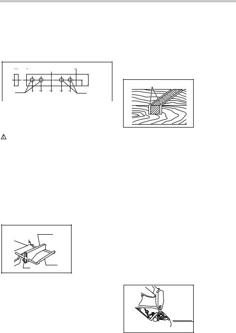
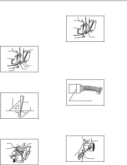
7.Wood facing
Use of wood facing helps to assure splinter-free cuts in workpieces. Attach a wood facing to the guide fence using the holes in the guide fence.
See the figure concerning the dimensions for a suggested wood facing.
Over 15mm (5/8") |
Over 420mm (16-1/2") |
||||
|
|
|
|
|
|
50mm-60mm (2"-2-3/8")
27mm (1-1/16")
1 |
|
|
|
|
|
1 |
|
85mm 70mm |
70mm 85mm |
||||||
|
|
||||||
|
(3-3/8") (2-3/4") |
(2-3/4") (3-3/8") |
|
||||
1. Holes
002206
 CAUTION:
•Use the straight wood of even thickness as the wood facing.
WARNING:
•Use screws to attach the wood facing to the guide fence. The screws should be installed so that the screw heads are below the surface of the wood facing so that they will not interfere with the
positioning of the material being cut. Misalignment of the material being cut can case unexpected movement during the cutting operation which may result in a loss of control and serious personal injury.
NOTICE:
•When the wood facing is attached, do not turn the turn base with the handle lowered. The blade and/or the wood facing will be damaged.
8.Cutting repetitive lengths
1. Set plate
12. Holder
3. Screw
2
3
001846
When cutting several pieces of stock to the same length, ranging from 220 mm (8-5/8") to 385 mm (15-1/8"), use of the set plate (optional accessory) will facilitate more efficient operation. Install the set plate on the holder (optional accessory) as shown in the figure.
Align the cutting line on your workpiece with either the left or right side of the groove in the kerf board, and while holding the workpiece from moving, move the set plate flush against the end of the
workpiece. Then secure the set plate with the screw. When the set plate is not used, loosen the screw and turn the set plate out of the way.
NOTE:
•Use of the holder-rod assembly (optional accessory) allows cutting repetitive lengths up to 2,200 mm (7.2 ft) approximately.
9.Groove cutting
1 |
1. Cut grooves with |
|
blade |
001563 |
|
A dado type cut can be made by proceeding as follows:
Adjust the lower limit position of the blade using the adjusting screw and the stopper arm to limit the cutting depth of the blade. Refer to "Stopper arm" section described on previously.
After adjusting the lower limit position of the blade, cut parallel grooves across the width of the workpiece using a slide (push) cut as shown in the figure. Then remove the workpiece material between the grooves with a chisel.
 WARNING:
•Do not attempt to perform this type of cut by using a wider type blade or dado blade. Attempting to make a groove cut with a wider blade or dado blade could lead to unexpected cutting results and kickback which may result in serious personal injury
•Be sure to return the stopper arm to the original position when performing other than groove cutting. Attempting to make cuts with the stopper arm in the incorrect position could lead to unexpected cutting results and kickback which may result in serious personal injury.
Carrying tool
1. Stopper pin
1

011300
18
012715
Make sure that the battery cartridge is removed. Secure the blade at 0° bevel angle and the turn base at the full right miter angle position. Secure the slide poles so that the lower slide pole is locked in the position of the carriage fully pulled to operator and the upper poles are locked in the position of the carriage fully pushed forward to the guide fence. Lower the handle fully and lock it in the lowered position by pushing in the stopper pin.
Carry the tool by holding both sides of the tool base as shown in the figure. If you remove the holders, dust bag, etc., you can carry the tool more easily.
 CAUTION:
•Always secure all moving portions before carrying the tool. If portions of the tool move or slide while being carried loss of control or balance may occur resulting in personal injury.
 WARNING:
•Stopper pin is only for carrying and storage purposes and should never be used for any cutting operations. The use of the stopper pin for cutting operations may cause unexpected movement of the saw blade resulting in kickback and serious personal injury.
MAINTENANCE
 CAUTION:
•Always be sure that the tool is switched off and the battery cartridge is removed before attempting to perform inspection or maintenance.
WARNING:
•Always be sure that the blade is sharp and clean for the best and safest performance.
Attempting a cut with a dull and /or dirty blade may cause kickback and result in a serious personal injury.
NOTICE:
•Never use gasoline, benzine, thinner, alcohol or the like. Discoloration, deformation or cracks may result.
Adjusting the cutting angle
This tool is carefully adjusted and aligned at the factory, but rough handling may have affected the alignment. If your tool is not aligned properly, perform the following:
1.Miter angle
1 |
2 |
1. Guide fence |
|
|
2. Hex socket bolt |
012585 |
|
|
Push the carriage toward the guide fence and tighten two clamp screws to secure the carriage. Loosen the grip which secures the turn base. Turn the turn base so that the pointer points to 0° on the miter scale. Then turn the turn base slightly clockwise and counterclockwise to seat the turn base in the 0° miter notch. (Leave as it is if the pointer does not point to 0°.) Loosen the hex socket bolt securing the guide fence using the hex wrench. Lower the handle fully and lock it in the lowered position by pushing in the stopper pin. Square the side of the blade with the face of the guide fence using a triangular rule, try-square, etc. Then securely tighten the hex socket bolt on the guide fence in order starting from the right side.
1. Triangular rule
1
002209
Make sure that the pointer points to 0° on the miter scale. If the pointer does not point to 0°, loosen the screw which secures the pointer and adjust the pointer so that it will point to 0°.
1 |
1. |
Screw |
2. |
Miter scale |
|
|
3. |
Pointer |
|
3 |
|
|
2 |
|
003942 |
|
|
19
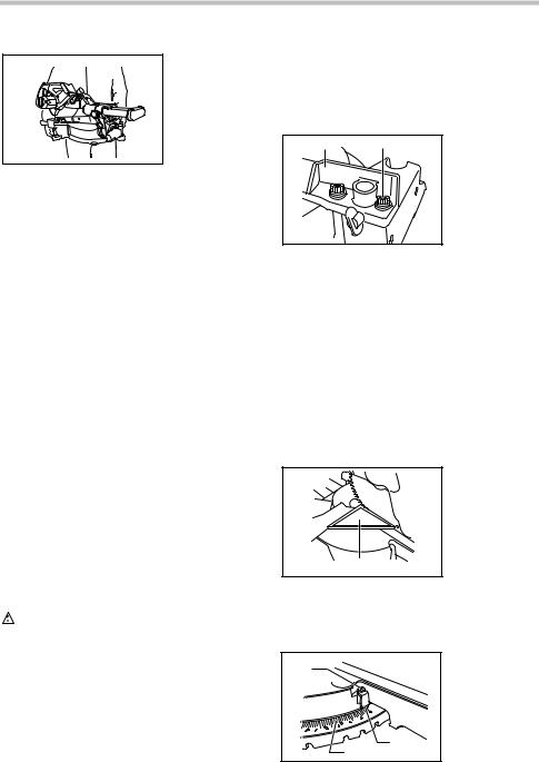
2.Bevel angle
(1)0° bevel angle
Push the carriage toward the guide fence and tighten two clamp screws to secure the carriage. Lower the handle fully and lock it in the lowered position by pushing in the stopper pin. Loosen the lever at the rear of the tool.
Turn the 0° bevel angle adjusting bolt (lower bolt) on the right side of the arm two or three revolutions counterclockwise to tilt the blade to the right.
1.Lever
12. Arm holder
3.0 degree bevel angle
|
|
adjusting bolt |
|
|
4. Arm |
|
34 5 |
5. Release button |
2 |
|
012589
Carefully square the side of the blade with the top surface of the turn base using the triangular rule, try-square, etc. by turning the 0° bevel angle adjusting bolt clockwise. Then tighten the lever securely.
1 |
1. |
Triangular rule |
2. Saw blade |
||
|
3. |
Top surface of |
|
2 |
turn table |
|
3 |
|
001819
Make sure that the pointer on the arm point to 0° on the bevel scale on the arm holder. If it does not point to 0°, loosen the screw which secures the pointer and adjust the pointer so that it will point to 0°.
1 |
|
3 |
1. |
Bevel scale |
2 |
2. |
Pointer |
||
|
|
3. |
Screw |
|
|
|
|
011306
(2)45° bevel angle
1. Left 45 bevel angle adjusting bolt
1
012590
Adjust the 45° bevel angle only after performing 0° bevel angle adjustment. To adjust left 45° bevel angle, loosen the lever and tilt the blade to the left fully. Make sure that the pointer on the arm points to 45° on the bevel scale on the arm holder. If the pointer does not point to 45°, turn the 45° bevel angle adjusting bolt (upper bolt) on the right side of the arm until the pointer points to 45°.
Replacing carbon brushes
1. Limit mark
1
001145
Remove and check the carbon brushes regularly. Replace when they wear down to the limit mark. Keep the carbon brushes clean and free to slip in the holders. Both carbon brushes should be replaced at the same time. Use only identical carbon brushes.
Use a screwdriver to remove the brush holder caps. Take out the worn carbon brushes, insert the new ones and secure the brush holder caps.
1. Brush holder
1 cap
2. Screwdriver
2
011307
After replacing brushes, install the battery cartridge and break in brushes by running tool with no load for about 10 minutes. Then check the tool while running and electric brake operation when releasing the switch trigger. If the electric brake is not working correctly, have the tool repaired by a Makita service center.
20
After use
•After use, wipe off chips and dust adhering to the tool with a cloth or the like. Keep the blade guard clean according to the directions in the previously covered section titled "Blade guard". Lubricate the sliding portions with machine oil to prevent rust.
•When storing the tool, pull the carriage toward you fully so that the slide pole is thoroughly inserted into the turn base.
To maintain product SAFETY and RELIABILITY, repairs, any other maintenance or adjustment should be performed by Makita Authorized or Factory Service Centers, always using Makita replacement parts.
OPTIONAL ACCESSORIES
WARNING:
•These Makita accessories or attachments are recommended for use with your Makita tool specified in this manual. The use of any other accessories or attachments may result in serious personal injury.
•Only use the Makita accessory or attachment
for its stated purpose. Misuse of an accessory or attachment may result in serious personal injury.
If you need any assistance for more details regarding these accessories, ask your local Makita Service Center.
•Carbide-tipped saw blades
•Vise assembly (Horizontal vise)
•Vertical vise
•Holder set
•Holder assembly
•Holder rod assembly
•Set plate
•Dust bag
•Triangular rule
•Hex wrench
•Makita genuine battery and charger
NOTE:
•Some items in the list may be included in the tool package as standard accessories. They may differ from country to country.
MAKITA LIMITED ONE YEAR WARRANTY
Warranty Policy
Every Makita tool is thoroughly inspected and tested before leaving the factory. It is warranted to be free of defects from workmanship and materials for the period of ONE YEAR from the date of original purchase. Should any trouble develop during this one year period, return the COMPLETE tool, freight prepaid, to one of Makita’s Factory or Authorized Service Centers. If inspection shows the trouble is caused by defective workmanship or material, Makita will repair (or at our option, replace) without charge.
This Warranty does not apply where:
repairs have been made or attempted by others:
repairs are required because of normal wear and tear:
the tool has been abused, misused or improperly maintained:
alterations have been made to the tool.
IN NO EVENT SHALL MAKITA BE LIABLE FOR ANY INDIRECT, INCIDENTAL OR CONSEQUENTIAL DAMAGES FROM THE SALE OR USE OF THE PRODUCT. THIS DISCLAIMER APPLIES BOTH DURING AND AFTER THE TERM OF THIS WARRANTY.
MAKITA DISCLAIMS LIABILITY FOR ANY IMPLIED WARRANTIES, INCLUDING IMPLIED WARRANTIES OF "MERCHANTABILITY" AND "FITNESS FOR A SPECIFIC PURPOSE," AFTER THE ONE YEAR TERM OF THIS WARRANTY.
This Warranty gives you specific legal rights, and you may also have other rights which vary from state to state. Some states do not allow the exclusion or limitation of incidental or consequential damages, so the above limitation or exclusion may not apply to you. Some states do not allow limitation on how long an implied warranty lasts, so the above limitation may not apply to you.
EN0006-1
21
 Loading...