


Makita DGA413, DGA464, DGA513, DGA511, DGA514 User Manual
...
|
EN |
Cordless Angle Grinder |
INSTRUCTION MANUAL |
8 |
|
|
|
|
|
|
|
Meuleuse d’Angle sans Fil |
MANUEL D’INSTRUCTIONS |
25 |
|
FR |
|||
|
|
|
|
|
|
|
Akku-Winkelschleifer |
BETRIEBSANLEITUNG |
43 |
|
DE |
|||
|
|
|
|
|
|
|
Smerigliatrice angolare a |
ISTRUZIONI PER L’USO |
62 |
|
IT |
|||
|
batteria |
|||
|
|
|
|
|
|
|
Haakse accuslijpmachine |
GEBRUIKSAANWIJZING |
81 |
|
NL |
|||
|
|
|
|
|
|
|
Esmeriladora Angular |
MANUAL DE |
99 |
|
ES |
|||
|
Inalámbrica |
INSTRUCCIONES |
||
|
|
|
||
|
|
Esmerilhadeira Angular a |
MANUAL DE INSTRUÇÕES |
117 |
|
PT |
|||
|
Bateria |
|||
|
|
|
|
|
|
|
Ledningsfri vinkelsliber |
BRUGSANVISNING |
135 |
|
DA |
|||
|
|
|
|
|
|
|
Φορητός γωνιακός |
ΕΓΧΕΙΡΙΔΙΟ ΟΔΗΓΙΩΝ |
152 |
|
EL |
|||
|
λειαντήρας |
|||
|
|
|
|
|
|
|
Akülü Avuç Taşlama Makinesi |
KULLANMA KILAVUZU |
171 |
|
TR |
|||
|
|
|
|
|
DGA411, DGA412,
DGA413, DGA414
DGA461, DGA462,
DGA463, DGA464
DGA511, DGA512,
DGA513, DGA514
|
2 |
|
1 |
|
3 |
Fig.1 |
Fig.5 |
1 |
2 |
Fig.2 |
1 |
1 |
Fig.6 |
1 |
|
|
|
|
|
|
|
|
|
|
|
|
|
|
|
|
|
|
|
|
|
|
|
|
|
|
|
|
|
|
|
|
|
|
|
|
|
|
|
|
|
|
|
|
Fig.3 |
|
|
|
Fig.7 |
|
|||||
|
|
|
|
|
|
|
|
|
|
|
Fig.4 |
Fig.8 |
2

Fig.9 |
Fig.13 |
Fig.10 |
Fig.14 |
Fig.11 |
Fig.15 |
Fig.12 |
Fig.16 |
3
|
2 |
|
1 |
Fig.17 |
Fig.21 |
|
15° |
Fig.18 |
Fig.22 |
Fig.19 |
Fig.23 |
Fig.20 |
Fig.24 |
4
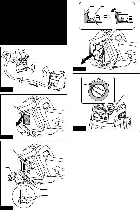
Fig.25 |
Fig.26 |
1 |
Fig.27 |
4 |
1 |
3 |
2 |
Fig.28 |
5 |
3 |
1 |
|
2 |
Fig.29 |
|
|
1 |
Fig.30

|
|
1 |
1 |
2 |
2 |
|
|
|
|
|
1 |
|
|
Fig.34 |
|
|
2 |
|
|
1 |
Fig.31 |
|
|
|
|
Fig.35 |
Fig.32 |
|
|
1
1
Fig.36
Fig.33
6

1 |
2 |
|
1 |
|
2 |
Fig.37 |
|
1 |
2 |
Fig.38 |
1 |
Fig.39 |
|
|
1 |
|
|
|
2 |
2 |
2 |
12 |
13 |
15 |
|
|||||
|
|
8 |
|
|
|
3 |
3 |
11 |
|
|
|
|
|
9 |
|
|
|
4 |
6 |
|
|
3 |
3 |
|
|
|
|
|
|
|
7 |
10 |
|
14 |
14 |
|
|
|
|||
5 |
|
|
|
|
|
|
5 |
|
|
5 |
5 |
Fig.40 |
|
|
|
|
|
7

ENGLISH (Original instructions)
SPECIFICATIONS
Model: |
DGA411 |
|
DGA412 |
|
DGA413 |
DGA414 |
|
|
|
|
|
|
|
Wheel diameter |
|
|
100 mm (4″) |
|
||
Max. wheel thickness |
|
|
|
6.4 mm |
|
|
|
|
|
|
|
|
|
Spindle thread |
|
|
|
M10 |
|
|
Rated speed (n) |
|
|
8,500 min-1 |
|
||
Overall length |
|
|
|
382 mm |
|
|
|
|
|
|
|
||
Rated voltage |
|
|
D.C. 18 V |
|
||
|
|
|
|
|
||
Net weight |
|
|
2.2 - 2.8 kg |
|
||
|
|
|
|
|
|
|
Electric brake |
|
- |
|
|
|
|
|
|
|
|
|
|
|
Wireless activation function |
- |
|
|
|
- |
|
|
|
|
|
|
|
|
Model: |
DGA461 |
|
DGA462 |
|
DGA463 |
DGA464 |
|
|
|
|
|
|
|
Wheel diameter |
|
|
115 mm (4-1/2″) |
|
||
Max. wheel thickness |
|
|
|
7.2 mm |
|
|
|
|
|
|
|
||
Spindle thread |
|
|
M14 or 5/8″ (country speciic) |
|
||
Rated speed (n) |
|
|
8,500 min-1 |
|
||
Overall length |
|
|
|
382 mm |
|
|
Rated voltage |
|
|
D.C. 18 V |
|
||
|
|
|
|
|
||
Net weight |
|
|
2.3 - 3.0 kg |
|
||
|
|
|
|
|
|
|
Electric brake |
|
- |
|
|
|
|
|
|
|
|
|
|
|
Wireless activation function |
- |
|
|
|
- |
|
|
|
|
|
|
|
|
|
|
|
|
|
|
|
Model: |
DGA511 |
|
DGA512 |
|
DGA513 |
DGA514 |
Wheel diameter |
|
|
125 mm (5″) |
|
||
Max. wheel thickness |
|
|
|
7.2 mm |
|
|
|
|
|
|
|
||
Spindle thread |
|
|
M14 or 5/8″ (country speciic) |
|
||
Rated speed (n) |
|
|
8,500 min-1 |
|
||
Overall length |
|
|
|
382 mm |
|
|
|
|
|
|
|
||
Rated voltage |
|
|
D.C. 18 V |
|
||
|
|
|
|
|||
Net weight |
2.3 - 3.0 kg |
|
2.4 - 3.0 kg |
|||
Electric brake |
|
- |
|
|
|
|
|
|
|
|
|
|
|
Wireless activation function |
- |
|
|
|
- |
|
|
|
|
|
|
|
|
•Due to our continuing program of research and development, the speciications herein are subject to change without notice.
•Speciications may differ from country to country.
•The weight may differ depending on the attachment(s), including the battery cartridge. The lightest and heavi - est combination, according to EPTA-Procedure 01/2014, are shown in the table.
Applicable battery cartridge
BL1815N / BL1820 / BL1820B / BL1830 / BL1830B / BL1840 / BL1840B / BL1850 / BL1850B / BL1860B
•Some of the battery cartridges listed above may not be available depending on your region of residence.
 WARNING: Only use the battery cartridges listed above. Use of any other battery cartridges may cause injury and/or ire.
Intended use
The tool is intended for grinding, sanding and cutting of metal and stone materials without the use of water.
8ENGLISH

Noise
The typical A-weighted noise level determined according to EN60745:
Model |
Sound pressure |
Sound power level |
Uncertainty (K) : |
|
level (LpA) : (dB(A)) |
(LWA) : (dB(A)) |
(dB(A)) |
DGA411 |
80 |
- |
3 |
DGA412 |
80 |
- |
3 |
DGA413 |
80 |
- |
3 |
DGA414 |
80 |
- |
3 |
DGA461 |
79 |
- |
3 |
DGA462 |
79 |
- |
3 |
DGA463 |
79 |
- |
3 |
DGA464 |
79 |
- |
3 |
DGA511 |
79 |
- |
3 |
DGA512 |
79 |
- |
3 |
DGA513 |
79 |
- |
3 |
DGA514 |
79 |
- |
3 |
The noise level under working may exceed 80 dB (A).

 WARNING: Wear ear protection.
Vibration
The vibration total value (tri-axial vector sum) determined according to EN60745:
Work mode: surface grinding with normal side grip
Model |
Vibration emission (ah, AG) : (m/s2) |
Uncertainty (K) : (m/s2) |
DGA411 |
4.5 |
1.5 |
DGA412 |
4.5 |
1.5 |
DGA413 |
4.5 |
1.5 |
DGA414 |
4.5 |
1.5 |
DGA461 |
6.5 |
1.5 |
DGA462 |
6.5 |
1.5 |
DGA463 |
6.5 |
1.5 |
DGA464 |
6.5 |
1.5 |
DGA511 |
6.5 |
1.5 |
DGA512 |
6.5 |
1.5 |
DGA513 |
6.5 |
1.5 |
DGA514 |
6.5 |
1.5 |
9ENGLISH

Work mode: surface grinding with anti vibration side grip
Model |
Vibration emission (ah, AG) : (m/s2) |
Uncertainty (K) : (m/s2) |
DGA411 |
4.0 |
1.5 |
DGA412 |
4.0 |
1.5 |
DGA413 |
4.0 |
1.5 |
DGA414 |
4.0 |
1.5 |
DGA461 |
6.0 |
1.5 |
DGA462 |
6.0 |
1.5 |
DGA463 |
6.0 |
1.5 |
DGA464 |
6.0 |
1.5 |
DGA511 |
6.0 |
1.5 |
DGA512 |
6.0 |
1.5 |
DGA513 |
6.0 |
1.5 |
DGA514 |
6.0 |
1.5 |
Work mode: disc sanding with normal side grip
Model |
Vibration emission (ah, DS) : (m/s2) |
Uncertainty (K) : (m/s2) |
|
DGA411 |
2.5 m/s2 or less |
1.5 |
|
DGA412 |
2.5 m/s2 or less |
1.5 |
|
DGA413 |
2.5 m/s2 or less |
1.5 |
|
DGA414 |
2.5 m/s2 or less |
1.5 |
|
DGA461 |
2.5 m/s2 or less |
1.5 |
|
DGA462 |
2.5 m/s2 or less |
1.5 |
|
DGA463 |
2.5 m/s2 or less |
1.5 |
|
DGA464 |
2.5 m/s2 or less |
1.5 |
|
DGA511 |
2.5 m/s2 |
or less |
1.5 |
DGA512 |
2.5 m/s2 |
or less |
1.5 |
DGA513 |
2.5 m/s2 |
or less |
1.5 |
DGA514 |
2.5 m/s2 |
or less |
1.5 |
Work mode: disc sanding with anti vibration side grip
Model |
Vibration emission (ah, DS) : (m/s2) |
Uncertainty (K) : (m/s2) |
|
DGA411 |
2.5 m/s2 or less |
1.5 |
|
DGA412 |
2.5 m/s2 or less |
1.5 |
|
DGA413 |
2.5 m/s2 or less |
1.5 |
|
DGA414 |
2.5 m/s2 or less |
1.5 |
|
DGA461 |
2.5 m/s2 or less |
1.5 |
|
DGA462 |
2.5 m/s2 or less |
1.5 |
|
DGA463 |
2.5 m/s2 or less |
1.5 |
|
DGA464 |
2.5 m/s2 or less |
1.5 |
|
DGA511 |
2.5 m/s2 |
or less |
1.5 |
DGA512 |
2.5 m/s2 |
or less |
1.5 |
DGA513 |
2.5 m/s2 |
or less |
1.5 |
DGA514 |
2.5 m/s2 |
or less |
1.5 |
NOTE: The declared vibration emission value has been measured in accordance with the standard test method and may be used for comparing one tool with another.
NOTE: The declared vibration emission value may also be used in a preliminary assessment of exposure.
10 ENGLISH
 WARNING: The vibration emission during actual use of the power tool can differ from the declared emission value depending on the ways in which the tool is used.
 WARNING: Be sure to identify safety measures to protect the operator that are based on an estimation of exposure in the actual conditions of use (taking account of all parts of the operating cycle such as the times when the tool is switched off and when it is running idle in addition to the trigger time).
 WARNING: The declared vibration emission value is used for main applications of the power tool. However if the power tool is used for other applications, the vibration emission value may be different.
EC Declaration of Conformity
For European countries only
The EC declaration of conformity is included as Annex A to this instruction manual.
SAFETY WARNINGS
General power tool safety warnings
 WARNING: Read all safety warnings, instructions, illustrations and speciications provided
with this power tool. Failure to follow all instructions listed below may result in electric shock, ire and/or serious injury.
Save all warnings and instruc-
tions for future reference.
The term "power tool" in the warnings refers to your mains-operated (corded) power tool or battery-operated (cordless) power tool.
Cordless grinder safety warnings
Safety Warnings Common for Grinding, Sanding, Wire Brushing, or Abrasive Cutting-Off Operations:
1.This power tool is intended to function as a grinder, sander, wire brush or cut-off tool.
Read all safety warnings, instructions, illustrations and speciications provided with this
power tool. Failure to follow all instructions listed below may result in electric shock, ire and/or serious injury.
2.Operations such as polishing are not recommended to be performed with this power
tool. Operations for which the power tool was not designed may create a hazard and cause per - sonal injury.
3.Do not use accessories which are not specii-
cally designed and recommended by the tool manufacturer. Just because the accessory can be attached to your power tool, it does not assure safe operation.
4.The rated speed of the accessory must be at
least equal to the maximum speed marked on the power tool. Accessories running faster than their rated speed can break and ly apart.
5.The outside diameter and the thickness of your
accessory must be within the capacity rating of your power tool. Incorrectly sized accessories cannot be adequately guarded or controlled.
6.Threaded mounting of accessories must
match the grinder spindle thread. For accessories mounted by langes, the arbour hole of the accessory must it the locating diameter of the lange. Accessories that do not match the
mounting hardware of the power tool will run out of balance, vibrate excessively and may cause loss of control.
7.Do not use a damaged accessory. Before each use inspect the accessory such as abrasive wheels for chips and cracks, backing pad for cracks, tear or excess wear, wire brush for loose or cracked wires. If power tool or accessory is dropped, inspect for damage or install an undamaged accessory. After inspecting and installing an accessory, position yourself and bystanders away from the plane of the rotating accessory and run the power tool at maximum
no-load speed for one minute. Damaged acces- sories will normally break apart during this test time.
8.Wear personal protective equipment. Depending on application, use face shield, safety goggles or safety glasses. As appropriate, wear dust mask, hearing protectors, gloves and workshop apron capable of stop-
ping small abrasive or workpiece fragments.
The eye protection must be capable of stopping lying debris generated by various operations. The dust mask or respirator must be capable of iltrating particles generated by your operation. Prolonged exposure to high intensity noise may cause hearing loss.
9.Keep bystanders a safe distance away from work area. Anyone entering the work area
must wear personal protective equipment.
Fragments of workpiece or of a broken accessory may ly away and cause injury beyond immediate area of operation.
10.Hold the power tool by insulated gripping surfaces only, when performing an operation
where the cutting tool may contact hidden wiring. Contact with a "live" wire will also make exposed metal parts of the power tool "live" and could give the operator an electric shock.
11.Never lay the power tool down until the accessory has come to a complete stop. The spinning accessory may grab the surface and pull the power tool out of your control.
12.Do not run the power tool while carrying it at your side. Accidental contact with the spinning accessory could snag your clothing, pulling the accessory into your body.
13.Regularly clean the power tool’s air vents. The motor’s fan will draw the dust inside the housing
and excessive accumulation of powdered metal may cause electrical hazards.
11 ENGLISH
14.Do not operate the power tool near lammable materials. Sparks could ignite these materials.
15.Do not use accessories that require liquid
coolants. Using water or other liquid coolants may result in electrocution or shock.
Kickback and Related Warnings
Kickback is a sudden reaction to a pinched or snagged rotating wheel, backing pad, brush or any other acces - sory. Pinching or snagging causes rapid stalling of the rotating accessory which in turn causes the uncon -
trolled power tool to be forced in the direction opposite of the accessory’s rotation at the point of the binding.
For example, if an abrasive wheel is snagged or pinched by the workpiece, the edge of the wheel that is
entering into the pinch point can dig into the surface of
the material causing the wheel to climb out or kick out.
The wheel may either jump toward or away from the
operator, depending on direction of the wheel’s move- ment at the point of pinching. Abrasive wheels may also
break under these conditions.
Kickback is the result of power tool misuse and/or
incorrect operating procedures or conditions and can be avoided by taking proper precautions as given below.
1.Maintain a irm grip on the power tool and position your body and arm to allow you to resist kickback forces. Always use auxiliary handle, if provided, for maximum control over
kickback or torque reaction during start-up.
The operator can control torque reactions or kick- back forces, if proper precautions are taken.
2.Never place your hand near the rotating accessory. Accessory may kickback over your hand.
3.Do not position your body in the area where power tool will move if kickback occurs.
Kickback will propel the tool in direction opposite to the wheel’s movement at the point of snagging.
4.Use special care when working corners, sharp edges etc. Avoid bouncing and snagging the
accessory. Corners, sharp edges or bouncing have a tendency to snag the rotating accessory and cause loss of control or kickback.
5.Do not attach a saw chain woodcarving blade or toothed saw blade. Such blades create frequent kickback and loss of control.
Safety Warnings Speciic for Grinding and Abrasive
Cutting-Off Operations:
1.Use only wheel types that are recommended for your power tool and the speciic guard designed for the selected wheel. Wheels for
which the power tool was not designed cannot be adequately guarded and are unsafe.
2.The grinding surface of centre depressed
wheels must be mounted below the plane of the guard lip. An improperly mounted wheel that projects through the plane of the guard lip cannot be adequately protected.
3.The guard must be securely attached to the power tool and positioned for maximum safety,
so the least amount of wheel is exposed towards the operator. The guard helps to protect the operator from broken wheel fragments, accidental contact with wheel and sparks that could ignite clothing.
4.Wheels must be used only for recommended
applications. For example: do not grind with the side of cut-off wheel. Abrasive cut-off wheels are
intended for peripheral grinding, side forces applied to these wheels may cause them to shatter.
5.Always use undamaged wheel langes that are
of correct size and shape for your selected wheel. Proper wheel langes support the wheel thus reducing the possibility of wheel breakage. Flanges for cut-off wheels may be different from grinding wheel langes.
6.Do not use worn down wheels from larger power tools. Wheel intended for larger power tool
is not suitable for the higher speed of a smaller tool and may burst.
Additional Safety Warnings Speciic for Abrasive
Cutting-Off Operations:
1.Do not “jam“ the cut-off wheel or apply excessive pressure. Do not attempt to make an
excessive depth of cut. Overstressing the wheel increases the loading and susceptibility to twisting
or binding of the wheel in the cut and the possibil- ity of kickback or wheel breakage.
2.Do not position your body in line with and
behind the rotating wheel. When the wheel, at the point of operation, is moving away from your body, the possible kickback may propel the spin - ning wheel and the power tool directly at you.
3.When wheel is binding or when interrupting a cut for any reason, switch off the power tool and hold the power tool motionless until the wheel comes to a complete stop. Never attempt to remove the cut-off wheel from the cut while the wheel is in motion otherwise
kickback may occur. Investigate and take corrective action to eliminate the cause of wheel binding.
4.Do not restart the cutting operation in the work-
piece. Let the wheel reach full speed and carefully re-enter the cut. The wheel may bind, walk up or kickback if the power tool is restarted in the workpiece.
5.Support panels or any oversized workpiece to minimize the risk of wheel pinching and kickback. Large workpieces tend to sag under their own weight. Supports must be placed under the workpiece near the line of cut and near the edge of the workpiece on both sides of the wheel.
6.Use extra caution when making a “pocket cut” into existing walls or other blind areas. The protruding wheel may cut gas or water pipes, elec - trical wiring or objects that can cause kickback.
Safety Warnings Speciic for Sanding Operations:
1.Do not use excessively oversized sanding disc paper. Follow manufacturers recommen-
dations, when selecting sanding paper. Larger sanding paper extending beyond the sanding pad presents a laceration hazard and may cause snagging, tearing of the disc or kickback.
Safety Warnings Speciic for Wire Brushing
Operations:
1.Be aware that wire bristles are thrown by the brush even during ordinary operation. Do not
overstress the wires by applying excessive load to the brush. The wire bristles can easily penetrate light clothing and/or skin.
12 ENGLISH

2.If the use of a guard is recommended for wire brushing, do not allow any interference of the
wire wheel or brush with the guard. Wire wheel or brush may expand in diameter due to work load and centrifugal forces.
Additional Safety Warnings:
1.When using depressed centre grinding wheels, be sure to use only iberglass-reinforced wheels.
2.NEVER USE Stone Cup type wheels with this grinder. This grinder is not designed for these types of wheels and the use of such a product may result in serious personal injury.
3.Be careful not to damage the spindle, the lange (especially the installing surface) or the lock nut. Damage to these parts could result in wheel breakage.
4.Make sure the wheel is not contacting the workpiece before the switch is turned on.
5.Before using the tool on an actual workpiece, let it run for a while. Watch for vibration or wobbling that could indicate poor installation or a poorly balanced wheel.
6.Use the speciied surface of the wheel to perform the grinding.
7.Do not leave the tool running. Operate the tool only when hand-held.
8.Do not touch the workpiece immediately after operation; it may be extremely hot and could burn your skin.
9.Observe the instructions of the manufacturer for correct mounting and use of wheels. Handle and store wheels with care.
10.Do not use separate reducing bushings or adaptors to adapt large hole abrasive wheels.
11.Use only langes speciied for this tool.
12.For tools intended to be itted with threaded hole wheel, ensure that the thread in the wheel is long enough to accept the spindle length.
13.Check that the workpiece is properly supported.
14.Pay attention that the wheel continues to rotate after the tool is switched off.
15.If working place is extremely hot and humid, or badly polluted by conductive dust, use a short-circuit breaker (30 mA) to assure operator safety.
16.Do not use the tool on any materials containing asbestos.
17.When use cut-off wheel, always work with the dust collecting wheel guard required by domestic regulation.
18.Cutting discs must not be subjected to any lateral pressure.
19.Do not use cloth work gloves during operation.
Fibers from cloth gloves may enter the tool, which causes tool breakage.
SAVE THESE INSTRUCTIONS.
 WARNING: DO NOT let comfort or familiarity with product (gained from repeated use) replace strict adherence to safety rules for the subject product. MISUSE or failure to follow the safety rules stated in this instruction manual may cause serious personal injury.
Important safety instructions for battery cartridge
1.Before using battery cartridge, read all instructions and cautionary markings on (1) battery charger, (2) battery, and (3) product using battery.
2.Do not disassemble battery cartridge.
3.If operating time has become excessively shorter, stop operating immediately. It may result in a risk of overheating, possible burns and even an explosion.
4.If electrolyte gets into your eyes, rinse them out with clear water and seek medical attention right away. It may result in loss of your eyesight.
5.Do not short the battery cartridge:
(1)Do not touch the terminals with any conductive material.
(2)Avoid storing battery cartridge in a container with other metal objects such as nails, coins, etc.
(3)Do not expose battery cartridge to water or rain.
A battery short can cause a large current low, overheating, possible burns and even a
breakdown.
6.Do not store the tool and battery cartridge in locations where the temperature may reach or exceed 50 °C (122 °F).
7.Do not incinerate the battery cartridge even if
it is severely damaged or is completely worn out. The battery cartridge can explode in a ire.
8.Be careful not to drop or strike battery.
9.Do not use a damaged battery.
10.The contained lithium-ion batteries are subject to the Dangerous Goods Legislation require-
ments.
For commercial transports e.g. by third parties, forwarding agents, special requirement on packaging and labeling must be observed.
For preparation of the item being shipped, consult- ing an expert for hazardous material is required. Please also observe possibly more detailed
national regulations.
Tape or mask off open contacts and pack up the battery in such a manner that it cannot move around in the packaging.
11.Follow your local regulations relating to disposal of battery.
12.Use the batteries only with the products speciied by Makita. Installing the batteries to non-compliant products may result in a ire, exces - sive heat, explosion, or leak of electrolyte.
SAVE THESE INSTRUCTIONS.
13 ENGLISH

 CAUTION: Only use genuine Makita batteries.
Use of non-genuine Makita batteries, or batteries that have been altered, may result in the battery bursting causing ires, personal injury and damage. It will
also void the Makita warranty for the Makita tool and charger.
Tips for maintaining maximum battery life
1.Charge the battery cartridge before completely discharged. Always stop tool operation and charge the battery cartridge when you notice less tool power.
2.Never recharge a fully charged battery cartridge. Overcharging shortens the battery service life.
3.Charge the battery cartridge with room temperature at 10 °C - 40 °C (50 °F - 104 °F). Let a hot battery cartridge cool down before charging it.
4.Charge the battery cartridge if you do not use it for a long period (more than six months).
Important safety instructions for wireless unit
1.Do not disassemble or tamper with the wireless unit.
2.Keep the wireless unit away from young children. If accidentally swallowed, seek medical attention immediately.
3.Use the wireless unit only with Makita tools.
4.Do not expose the wireless unit to rain or wet conditions.
5.Do not use the wireless unit in places where the temperature exceeds 50°C (122°F).
6.Do not operate the wireless unit in places where medical instruments, such as heart pace makers are near by.
7.Do not operate the wireless unit in places
where automated devices are near by. If oper- ated, automated devices may develop malfunction or error.
8.The wireless unit can produce electromagnetic ields (EMF) but they are not harmful to the user.
9.The wireless unit is an accurate instrument. Be careful not to drop or strike the wireless unit.
10.Avoid touching the terminal of the wireless unit with bare hands or metallic materials.
11.Always remove the battery on the tool when installing the wireless unit.
12.When opening the lid of the slot, avoid the place where dust and water may come into the slot. Always keep the inlet of the slot clean.
13.Always insert the wireless unit in the correct direction.
14.Do not press the wireless activation button on the wireless unit too hard and/or press the button with an object with a sharp edge.
15.Always close the lid of the slot when operating.
16.Do not remove the wireless unit from the slot
while the power is being supplied to the tool.
Doing so may cause a malfunction of the wireless unit.
17.Do not remove the sticker on the wireless unit.
18.Do not put any sticker on the wireless unit.
19.Do not leave the wireless unit in a place where static electricity or electrical noise could be generated.
20.Do not leave the wireless unit in a place subject to high heat, such as a car sitting in the sun.
21.Do not leave the wireless unit in a dusty or powdery place or in a place corrosive gas could be generated.
22.Sudden change of the temperature may bedew the wireless unit. Do not use the wireless unit until the dew is completely dried.
23.When cleaning the wireless unit, gently wipe with a dry soft cloth. Do not use benzine, thinner, conductive grease or the like.
24.When storing the wireless unit, keep it in the supplied case or a static-free container.
25.Do not insert any devices other than Makita wireless unit into the slot on the tool.
26.Do not use the tool with the lid of the slot damaged. Water, dust, and dirt come into the slot may cause malfunction.
27.Do not pull and/or twist the lid of the slot more than necessary. Restore the lid if it comes off from the tool.
28.Replace the lid of the slot if it is lost or damaged.
SAVE THESE INSTRUCTIONS.
14 ENGLISH
FUNCTIONAL
DESCRIPTION
 CAUTION: Always be sure that the tool is switched off and the battery cartridge is removed before adjusting or checking function on the tool.
Installing or removing battery cartridge
 CAUTION: Always switch off the tool before installing or removing of the battery cartridge.
 CAUTION: Hold the tool and the battery cartridge irmly when installing or removing battery cartridge.
Failure to hold the tool and the battery cartridge irmly may cause them to slip off your hands and result in damage to the tool and battery cartridge and a personal injury.
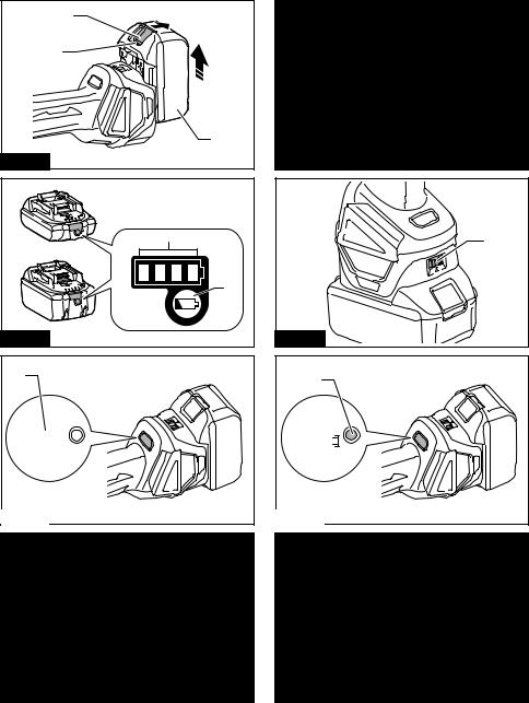
► Fig.1: 1. Red indicator 2. Button 3. Battery cartridge
To remove the battery cartridge, slide it from the tool while sliding the button on the front of the cartridge.
To install the battery cartridge, align the tongue on the battery cartridge with the groove in the housing and slip it into place. Insert it all the way until it locks in place with a little click. If you can see the red indicator on the upper side of the button, it is not locked completely.
 CAUTION: Always install the battery cartridge fully until the red indicator cannot be seen. If not, it may accidentally fall out of the tool, causing injury to you or someone around you.
 CAUTION: Do not install the battery cartridge forcibly. If the cartridge does not slide in easily, it is not being inserted correctly.
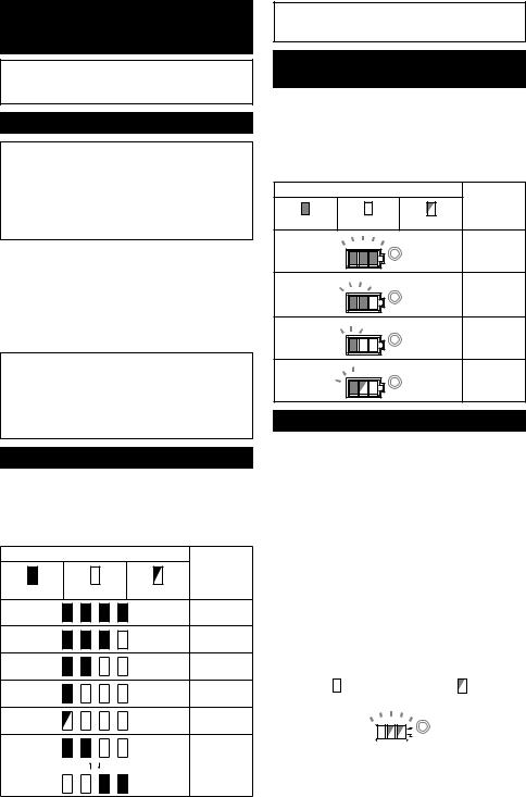
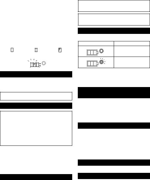
Indicating the remaining battery capacity
Only for battery cartridges with the indicator
► Fig.2: 1. Indicator lamps 2. Check button
Press the check button on the battery cartridge to indi - cate the remaining battery capacity. The indicator lamps
light up for a few seconds.
|
Indicator lamps |
Remaining |
|
|
capacity |
Lighted |
Off |
Blinking |
|
|
75% to 100% |
|
|
50% to 75% |
|
|
25% to 50% |
|
|
0% to 25% |
|
|
Charge the |
|
|
battery. |
|
|
The battery |
|
|
may have |
|
|
malfunctioned. |
NOTE: Depending on the conditions of use and the ambient temperature, the indication may differ slightly from the actual capacity.
Indicating the remaining battery capacity
Country speciic
When you turn the tool on, the battery indicator shows the remaining battery capacity.
► Fig.3: 1. Battery indicator
The remaining battery capacity is shown as the follow - ing table.
|
Battery indicator status |
Remaining |
|
|
|
|
battery |
|
|
|
capacity |
On |
Off |
Blinking |
|
|
|
|
50% to 100% |
|
|
|
20% to 50% |
|
|
|
0% to 20% |
|
|
|
Charge the |
|
|
|
battery |
Tool / battery protection system
The tool is equipped with a tool/battery protection sys- tem. This system automatically cuts off power to the motor to extend tool and battery life. The tool will auto- matically stop during operation if the tool or battery is placed under one of the following conditions:
Overload protection
When the tool is operated in a manner that causes it to draw an abnormally high current, the tool automatically stops without any indication. In this situation, turn the
tool off and stop the application that caused the tool to become overloaded. Then turn the tool on to restart.
Overheat protection
When the tool is overheated, the tool stops automati- cally and the battery indicator shows following state. In
this situation, let the tool cool before turning the tool on again.
|
|
|
|
|
|
|
|
|
|
|
|
|
|
|
|
|
|
On |
|
|
|
Blinking |
||||
|
|
|
|
|
|
|
|
|
|
|
|
|
|
|
|
|
|
|
|
|
|
|
|
|
|
|
|
|
|
|
|
|
|
|
|
If the tool does not start, the battery may be overheated. In this situation, let the battery cool before starting the
tool again.
15 ENGLISH
Overdischarge protection
When the battery capacity is not enough, the tool stops automatically. In this case, remove the battery from the tool and charge the battery.
Releasing protection lock
When the protection system works repeatedly, the tool is locked and the battery indicator shows the following state.
In this situation, the tool does not start even if turning the tool off and on. To release the protection lock, remove the battery, set it to the battery charger and wait until the charging inishes.
|
|
|
|
|
|
|
|
|
|
|
|
|
|
|
|
|
|
|
|
|
|
|
|
On |
|
|
Off |
Blinking |
|||||||
|
|
|
|
|
|
|
|
|
|
|
|
|
|
|
|
|
|
|
|
|
|
|
|
|
|
|
|
|
|
|
|
|
|
|
|
|
|
|
|
|
|
|
|
|
|
|
|
Shaft lock
Press the shaft lock to prevent spindle rotation when installing or removing accessories.
► Fig.4: 1. Shaft lock
NOTICE: Never actuate the shaft lock when the spindle is moving. The tool may be damaged.
Switch action
 CAUTION: Before installing the battery cartridge into the tool, always check to see that the slide switch actuates properly and returns to the "OFF" position when the rear of the slide switch is depressed.
 CAUTION: Switch can be locked in "ON" position for ease of operator comfort during extended
use. Apply caution when locking tool in "ON" position and maintain irm grasp on tool.
To start the tool, slide the slide switch toward the “I (ON)” position by pushing the rear of the slide switch.
For continuous operation, press the front of the slide
switch to lock it.
To stop the tool, press the rear of the slide switch, then slide it toward the “O (OFF)” position.
► Fig.5: 1. Slide switch
Speed adjusting dial
The rotation speed of the tool can be changed by turning the speed adjusting dial. The table below shows the num-
ber on the dial and the corresponding rotation speed.
► Fig.6: 1. Speed adjusting dial
Number |
Speed |
|
|
1 |
3,000 min-1 |
2 |
4,500 min-1 |
3 |
6,000 min-1 |
4 |
7,500 min-1 |
5 |
8,500 min-1 |
NOTICE: If the tool is operated continuously at low speed for a long time, the motor will get overloaded, resulting in tool malfunction.
NOTICE: When changing the speed dial from "5" to "1", turn the dial counterclockwise. Do not turn the dial clockwise forcibly.
Automatic speed change function
► Fig.7: 1. Mode indicator
Mode indicator status |
Operation mode |
|
High speed mode |
|
High torque mode |
This tool has "high speed mode" and "high torque mode". It automatically changes operation mode
depending on the work load. When mode indicator lights up during operation, the tool is in high torque mode.
Accidental re-start preventive function
Even if the battery cartridge is installed on the tool with the slide switch in the "I (ON)" position, the tool does
not start.
To start the tool, irst slide the slide switch toward the "O (OFF)" position and then slide it toward the "I (ON)"
position.
Electronic torque control function
The tool electronically detects situations where the wheel or accessory may be at risk to be bound. In the situation, the tool is automatically shut off to prevent
further rotation of the spindle (it does not prevent kickback).
To restart the tool, switch off the tool irst, remove the cause of sudden drop in the rotation speed, and then turn the tool on.
Soft start feature
Soft start feature reduces starting reaction.
Electric brake
For model DGA413/DGA414/DGA463/DGA464/ DGA513/DGA514 only
Electric brake is activated after the tool is switched off.
The brake does not work when the power supply is shut down, such as the battery is removed accidentally, with
the switch still on.
16 ENGLISH

ASSEMBLY
 CAUTION: Always be sure that the tool is switched off and the battery cartridge is removed before adjusting or checking function on the tool.
Installing side grip (handle)
 CAUTION: Always be sure that the side grip is installed securely before operation.
Screw the side grip securely on the position of the tool as shown in the igure.
► Fig.8
Installing or removing wheel guard
(For depressed center wheel, lap disc, lex wheel, wire wheel brush / abrasive
cut-off wheel, diamond wheel)
 WARNING: When using a depressed center wheel, lap disc, lex wheel or wire wheel brush, the wheel guard must be itted on the tool so that the closed side
of the guard always points toward the operator.
 WARNING: When using an abrasive cut-off / diamond wheel, be sure to use only the special
wheel guard designed for use with cut-off wheels.
(In some European countries, when using a diamond wheel, the ordinary guard can be used. Follow the regulations in your country.)
For tool with locking screw type wheel guard
Mount the wheel guard with the protrusions on the
wheel guard band aligned with the notches on the bear- ing box. Then rotate the wheel guard to such an angle
that it can protect the operator according to work. Be sure to tighten the screw securely.
To remove wheel guard, follow the installation proce - dure in reverse.
► Fig.9: 1. Wheel guard 2. Bearing box 3. Screw
For tool with clamp lever type wheel guard
Loosen the screw, and then pull the lever in the direction of the arrow. Mount the wheel guard with the protrusions
on the wheel guard band aligned with the notches on the bearing box. Then rotate the wheel guard to such an
angle that it can protect the operator according to work.
►Fig.10: 1. Wheel guard 2. Bearing box 3. Screw
4.Lever
Pull the lever in direction of the arrow. Then tighten the
wheel guard with fastening the screw. Be sure to tighten the screw securely. The setting angle of the wheel guard can be adjusted with the lever.
► Fig.11: 1. Screw 2. Lever
To remove wheel guard, follow the installation proce - dure in reverse.
Installing or removing depressed center wheel or lap disc
Optional accessory
 WARNING: When using a depressed center wheel or lap disc, the wheel guard must be itted
on the tool so that the closed side of the guard always points toward the operator.
 CAUTION: Make sure that the mounting part of the inner lange its into the inner diameter of the depressed center wheel / lap disc perfectly.
Mounting the inner lange on the wrong side may result in the dangerous vibration.
Mount the inner lange onto the spindle.
Make sure to it the dented part of the inner lange onto
the straight part at the bottom of the spindle.
Fit the depressed center wheel / lap disc on the inner lange and screw the lock nut onto the spindle.
►Fig.12: 1. Lock nut 2. Depressed center wheel
3.Inner lange 4. Mounting part
To tighten the lock nut, press the shaft lock irmly so
that the spindle cannot revolve, then use the lock nut wrench and securely tighten clockwise.
► Fig.13: 1. Lock nut wrench 2. Shaft lock
To remove the wheel, follow the installation procedure in reverse.
Installing or removing lex wheel
Optional accessory
 WARNING: Always use supplied guard when lex wheel is on tool. Wheel can shatter during use and guard helps to reduce chances of personal injury.
►Fig.14: 1. Lock nut 2. Flex wheel 3. Back up pad
4.Inner lange
Follow instructions for depressed center wheel but also use back up pad over wheel. See order of assembly on
accessories page in this manual.
Installing or removing abrasive disc
Optional accessory
NOTE: Use sander accessories speciied in this man - ual. These must be purchased separately.
For 100 mm (4″) model
►Fig.15: 1. Sanding lock nut 2. Abrasive disc
3.Rubber pad 4. Inner lange
1.Mount the inner lange onto the spindle.
2.Mount the rubber pad onto the spindle.
3.Fit the disc on the rubber pad and screw the sanding lock nut onto the spindle.
4.Hold the spindle with the shaft lock, and securely tighten the sanding lock nut clockwise with the lock nut wrench.
To remove the disc, follow the installation procedure in reverse.
17 ENGLISH

For 115 mm (4 - 1/2″) / 125 mm (5″) model
►Fig.16: 1. Sanding lock nut 2. Abrasive disc
3.Rubber pad
1.Mount the rubber pad onto the spindle.
2.Fit the disc on the rubber pad and screw the sanding lock nut onto the spindle.
3.Hold the spindle with the shaft lock, and securely tighten the sanding lock nut clockwise with the lock nut wrench.
To remove the disc, follow the installation procedure in reverse.
Connecting a vacuum cleaner
Optional accessory
 WARNING: Never vacuum metal particles
created by grinding/cutting/sanding operation.
Metal particles created by such operation are so hot that they ignite dust and the ilter inside the vacuum
cleaner.
To avoid dusty environment caused by masonry cut- ting, use a dust collecting wheel guard and a vacuum cleaner.
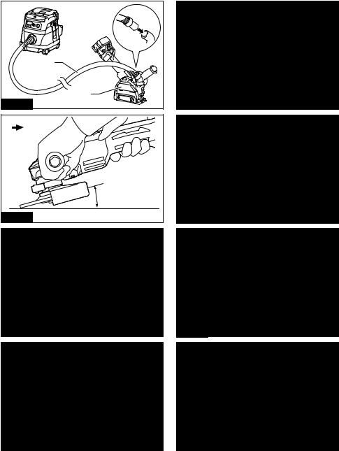
Refer to the instruction manual attached to the dust collecting wheel guard for assembling and using it. ► Fig.17: 1. Dust collecting wheel guard 2. Hose of
the vacuum cleaner
OPERATION
 WARNING: It should never be necessary to force the tool. The weight of the tool applies ade -
quate pressure. Forcing and excessive pressure could cause dangerous wheel breakage.
 WARNING: ALWAYS replace wheel if tool is dropped while grinding.
 WARNING: NEVER bang or hit grinding disc or wheel onto work.
 WARNING: Avoid bouncing and snagging
the wheel, especially when working corners, sharp edges etc. This can cause loss of control and
kickback.
 WARNING: NEVER use tool with wood cutting
blades and other saw blades. Such blades when used on a grinder frequently kick and cause loss of control leading to personal injury.
 CAUTION: Never switch on the tool when it is in contact with the workpiece, it may cause an injury to operator.
 CAUTION: Always wear safety goggles or a face shield during operation.
 CAUTION: After operation, always switch off the tool and wait until the wheel has come to a complete stop before putting the tool down.
 CAUTION: ALWAYS hold the tool irmly with one hand on housing and the other on the side grip (handle).
Grinding and sanding operation
► Fig.18
Turn the tool on and then apply the wheel or disc to the workpiece.
In general, keep the edge of the wheel or disc at an angle of about 15° to the workpiece surface.
During the break-in period with a new wheel, do not work the grinder in forward direction or it may cut into
the workpiece. Once the edge of the wheel has been rounded off by use, the wheel may be worked in both
forward and backward direction.
Operation with abrasive cut-off / diamond wheel
Optional accessory
 WARNING: When using an abrasive cut-off / diamond wheel, be sure to use only the special
wheel guard designed for use with cut-off wheels.
(In some European countries, when using a diamond wheel, the ordinary guard can be used. Follow the regulations in your country.)
 WARNING: NEVER use cut-off wheel for side grinding.
 WARNING: Do not "jam" the wheel or apply excessive pressure. Do not attempt to make an
excessive depth of cut. Overstressing the wheel increases the loading and susceptibility to twisting or binding of the wheel in the cut and the possibility
of kickback, wheel breakage and overheating of the motor may occur.
 WARNING: Do not start the cutting operation in the workpiece. Let the wheel reach full speed
and carefully enter into the cut moving the tool forward over the workpiece surface. The wheel may bind, walk up or kickback if the power tool is
started in the workpiece.
 WARNING: During cutting operations, never
change the angle of the wheel. Placing side pres- sure on the cut-off wheel (as in grinding) will cause
the wheel to crack and break, causing serious per- sonal injury.
 WARNING: A diamond wheel shall be operated perpendicular to the material being cut.
18 ENGLISH

► Fig.19: 1. Lock nut 2. Abrasive cut-off wheel / dia - mond wheel 3. Inner lange 4. Wheel guard
for abrasive cut-off wheel / diamond wheel
As for the installation, follow the instructions for depressed center wheel.
The direction for mounting the lock nut and the inner lange varies by wheel type and thickness.
Refer to the following igures.
For 100 mm (4″) model
When installing the abrasive cut-off wheel:
► Fig.20: 1. Lock nut 2. Abrasive cut-off wheel
(Thinner than 4mm (5/32")) 3. Abrasive cutoff wheel (4mm (5/32") or thicker) 4. Inner lange
When installing the diamond wheel:
► Fig.21: 1. Lock nut 2. Diamond wheel (Thinner than 4mm (5/32″)) 3. Diamond wheel (4mm
(5/32″) or thicker) 4. Inner lange
For 115 mm (4 - 1/2″) / 125 mm (5″) model
When installing the abrasive cut-off wheel:
► Fig.22: 1. Lock nut 2. Abrasive cut-off wheel
(Thinner than 4mm (5/32")) 3. Abrasive cutoff wheel (4mm (5/32") or thicker) 4. Inner lange
When installing the diamond wheel:
► Fig.23: 1. Lock nut 2. Diamond wheel (Thinner than 4mm (5/32″)) 3. Diamond wheel (4mm
(5/32″) or thicker) 4. Inner lange
Operation with wire cup brush
Optional accessory
 CAUTION: Check operation of brush by running tool with no load, insuring that no one is in front of or in line with brush.
 CAUTION: Do not use brush that is damaged,
or which is out of balance. Use of damaged brush could increase potential for injury from contact with
broken brush wires.
► Fig.24: 1. Wire cup brush
Remove the battery cartridge from the tool and place it upside down allowing easy access to spindle. Remove any accessories on spindle. Thread wire cup
brush onto spindle and tighten with supplied wrench.
NOTICE: Avoid applying too much pressure
which causes over bending of wires when using brush. It may lead to premature breakage.
Operation with wire wheel brush
Optional accessory
 CAUTION: Check operation of wire wheel brush by running tool with no load, insuring that no one is in front of or in line with the wire wheel brush.
 CAUTION: Do not use wire wheel brush that is damaged, or which is out of balance. Use of
damaged wire wheel brush could increase potential for injury from contact with broken wires.
 CAUTION: ALWAYS use guard with wire wheel brushes, assuring diameter of wheel its
inside guard. Wheel can shatter during use and guard helps to reduce chances of personal injury.
► Fig.25: 1. Wire wheel brush
Remove the battery cartridge from the tool and place it upside down allowing easy access to spindle.
Remove any accessories on spindle. Thread wire wheel brush onto spindle and tighten with the wrenches.
NOTICE: Avoid applying too much pressure
which causes over bending of wires when using wire wheel brush. It may lead to premature
breakage.
WIRELESS ACTIVATION FUNCTION
For DGA412/DGA414/DGA462/DGA464/DGA512/ DGA514 only
What you can do with the wireless activation function
The wireless activation function enables clean and com- fortable operation. By connecting a supported vacuum cleaner to the tool, you can run the vacuum cleaner automatically along with the switch operation of the tool.
► Fig.26
To use the wireless activation function, prepare follow- ing items:
•A wireless unit
•A vacuum cleaner which supports the wireless activation function
The overview of the wireless activation function setting is as follows. Refer to each section for detail procedures.
1.Installing the wireless unit
2.Tool registration for the vacuum cleaner
3.Starting the wireless activation function
19 ENGLISH

Installing the wireless unit

 CAUTION: Place the tool on a lat and stable surface when installing the wireless unit.
NOTICE: Clean the dust and dirt on the tool
before installing the wireless unit. Dust or dirt may cause malfunction if it comes into the slot of the
wireless unit.
NOTICE: To prevent the malfunction caused by static, touch a static discharging material, such as a metal part of the tool, before picking up the wireless unit.
NOTICE: When installing the wireless unit, always be sure that the wireless unit is inserted in the correct direction and the lid is completely closed.
1.Open the lid on the tool as shown in the igure. ► Fig.27: 1. Lid
2.Insert the wireless unit to the slot and then close the lid.
When inserting the wireless unit, align the projections with the recessed portions on the slot.
►Fig.28: 1. Wireless unit 2. Projection 3. Lid
4.Recessed portion
When removing the wireless unit, open the lid slowly. The hooks on the back of the lid will lift the wireless unit as you pull up the lid.
► Fig.29: 1. Wireless unit 2. Hook 3. Lid
After removing the wireless unit, keep it in the supplied case or a static-free container.
NOTICE: Always use the hooks on the back of the lid when removing the wireless unit. If the
hooks do not catch the wireless unit, close the lid completely and open it slowly again.
Tool registration for the vacuum cleaner
NOTE: A Makita vacuum cleaner supporting the wireless activation function is required for the tool registration.
NOTE: Finish installing the wireless unit to the tool before starting the tool registration.
NOTE: During the tool registration, do not pull the switch trigger or turn on the power switch on the vacuum cleaner.
NOTE: Refer to the instruction manual of the vacuum cleaner, too.
If you wish to activate the vacuum cleaner along with the switch operation of the tool, inish the tool registra-
tion beforehand.
1.Install the batteries to the vacuum cleaner and the
tool.
2.Set the stand-by switch on the vacuum cleaner to "AUTO".
► Fig.30: 1. Stand-by switch
3.Press the wireless activation button on the vac-
uum cleaner for 3 seconds until the wireless activation lamp blinks in green. And then press the wireless acti - vation button on the tool in the same way.
► Fig.31: 1. Wireless activation button 2. Wireless activation lamp
If the vacuum cleaner and the tool are linked success- fully, the wireless activation lamps will light up in green
for 2 seconds and start blinking in blue.
NOTE: The wireless activation lamps inish blinking in green after 20 seconds elapsed. Press the wireless activation button on the tool while the wireless activation lamp on the cleaner is blinking. If the wireless
activation lamp does not blink in green, push the wire- less activation button briely and hold it down again.
NOTE: When performing two or more tool registra- tions for one vacuum cleaner, inish the tool registra - tion one by one.
Starting the wireless activation function
NOTE: Finish the tool registration for the vacuum cleaner prior to the wireless activation.
NOTE: Refer to the instruction manual of the vacuum cleaner, too.
After registering a tool to the vacuum cleaner, the vacuum cleaner will automatically runs along with the
switch operation of the tool.
1.Install the wireless unit to the tool.
2.Connect the hose of the vacuum cleaner with the tool.
► Fig.32
3.Set the stand-by switch on the vacuum cleaner to "AUTO".
► Fig.33: 1. Stand-by switch
4.Push the wireless activation button on the tool briely. The wireless activation lamp will blink in blue.
► Fig.34: 1. Wireless activation button 2. Wireless activation lamp
5. Pull the switch trigger of the tool. Check if the vacuum cleaner runs while the switch trigger is being pulled.
To stop the wireless activation of the vacuum cleaner, push the wireless activation button on the tool.
NOTE: The wireless activation lamp on the tool will
stop blinking in blue when there is no operation for
2 hours. In this case, set the stand-by switch on the vacuum cleaner to "AUTO" and push the wireless
activation button on the tool again.
NOTE: The vacuum cleaner starts/stops with a delay. There is a time lag when the vacuum cleaner detects
a switch operation of the tool.
NOTE: The transmission distance of the wireless unit may vary depending on the location and surrounding
circumstances.
NOTE: When two or more tools are registered to one vacuum cleaner, the vacuum cleaner may start run - ning even if you don't pull the switch trigger because
an other user is using the wireless activation function.
20 ENGLISH
Description of the wireless activation lamp status
► Fig.35: 1. Wireless activation lamp
The wireless activation lamp shows the status of the wireless activation function. Refer to the table below for the meaning of the lamp status.
Status |
|
Wireless activation lamp |
Description |
|||
|
|
|
|
|
|
|
|
Color |
|
|
|
Duration |
|
|
|
On |
|
Blinking |
|
|
Standby |
Blue |
|
|
|
2 hours |
The wireless activation of the vacuum cleaner is available. The |
|
|
|
|
|
|
lamp will automatically turn off when no operation is performed |
|
|
|
|
|
|
for 2 hours. |
|
|
|
|
|
|
|
|
|
|
|
|
When |
The wireless activation of the vacuum cleaner is available and the |
|
|
|
|
|
the tool is |
tool is running. |
|
|
|
|
|
running. |
|
|
|
|
|
|
|
|
Tool |
Green |
|
|
|
20 seconds |
Ready for the tool registration. Waiting for the registration by the |
registration |
|
|
|
|
|
vacuum cleaner. |
|
|
|
|
|
|
|
|
|
|
|
|
2 seconds |
The tool registration has been inished. The wireless activation |
|
|
|
|
|
|
lamp will start blinking in blue. |
Cancelling |
Red |
|
|
|
20 seconds |
Ready for the cancellation of the tool registration. Waiting for the |
tool |
|
|
|
|
|
cancellation by the vacuum cleaner. |
registration |
|
|
|
|
2 seconds |
The cancellation of the tool registration has been inished. The |
|
|
|
|
|
||
|
|
|
|
|
|
wireless activation lamp will start blinking in blue. |
|
|
|
|
|
|
|
Others |
Red |
|
|
|
3 seconds |
The power is supplied to the wireless unit and the wireless activa - |
|
|
|
|
|
|
tion function is starting up. |
|
|
|
|
|
|
|
|
Off |
- |
|
- |
The wireless activation of the vacuum cleaner is stopped. |
|
Cancelling tool registration for the vacuum cleaner
Perform the following procedure when cancelling the tool registration for the vacuum cleaner.
1.Install the batteries to the vacuum cleaner and the
tool.
2.Set the stand-by switch on the vacuum cleaner to "AUTO".
► Fig.36: 1. Stand-by switch
3.Press the wireless activation button on the vac- uum cleaner for 6 seconds. The wireless activation lamp blinks in green and then become red. After that,
press the wireless activation button on the tool in the same way.
► Fig.37: 1. Wireless activation button 2. Wireless activation lamp
If the cancellation is performed successfully, the wire - less activation lamps will light up in red for 2 seconds and start blinking in blue.
NOTE: The wireless activation lamps inish blinking in red after 20 seconds elapsed. Press the wireless activation button on the tool while the wireless activation lamp on the cleaner is blinking. If the wireless acti-
vation lamp does not blink in red, push the wireless activation button briely and hold it down again.
21 ENGLISH

Troubleshooting for wireless activation function
Before asking for repairs, conduct your own inspection irst. If you ind a problem that is not explained in the manual, do not attempt to dismantle the tool. Instead, ask Makita Authorized Service Centers, always using Makita replace-
ment parts for repairs.
State of abnormality |
Probable cause (malfunction) |
Remedy |
The wireless activation lamp does |
The wireless unit is not installed into |
Install the wireless unit correctly. |
not light/blink. |
the tool. |
|
|
The wireless unit is improperly installed |
|
|
into the tool. |
|
|
|
|
|
The terminal of the wireless unit and/or |
Gently wipe off dust and dirt on the terminal of the |
|
the slot is dirty. |
wireless unit and clean the slot. |
|
The wireless activation button on the |
Push the wireless activation button on the tool |
|
tool has not been pushed. |
briely. |
|
The stand-by switch on the vacuum |
Set the stand-by switch on the vacuum cleaner to |
|
cleaner is not set to "AUTO". |
"AUTO". |
|
No power supply |
Supply the power to the tool and the vacuum |
|
|
cleaner. |
|
|
|
Cannot inish tool registration / can - |
The wireless unit is not installed into |
Install the wireless unit correctly. |
celling tool registration successfully. |
the tool. |
|
|
The wireless unit is improperly installed |
|
|
into the tool. |
|
|
|
|
|
The terminal of the wireless unit and/or |
Gently wipe off dust and dirt on the terminal of the |
|
the slot is dirty. |
wireless unit and clean the slot. |
|
The stand-by switch on the vacuum |
Set the stand-by switch on the vacuum cleaner to |
|
cleaner is not set to "AUTO". |
"AUTO". |
|
No power supply |
Supply the power to the tool and the vacuum |
|
|
cleaner. |
|
|
|
|
Incorrect operation |
Push the wireless activation button briely and |
|
|
perform the tool registration/cancellation procedures |
|
|
again. |
|
|
|
|
The tool and vacuum cleaner is away |
Get the tool and vacuum cleaner closer to each |
|
from each other (out of the transmission |
other. The maximum transmission distance is |
|
range). |
approximately 10 m however it may vary according |
|
|
to the circumstances. |
|
|
|
|
Before inishing the tool registration/ |
Push the wireless activation button briely and |
|
cancellation; |
perform the tool registration/cancellation procedures |
|
- the switch trigger on the tool is pulled |
again. |
|
or; |
|
|
- the power button on the vacuum |
|
|
cleaner is turned on. |
|
|
|
|
|
The tool registration procedures for the |
Perform the tool registration procedures for both the |
|
tool or vacuum cleaner has not inished. |
tool and the vacuum cleaner at the same timing. |
|
Radio disturbance by other appliances |
Keep the tool and vacuum cleaner away from the |
|
which generate high-intensity radio |
appliances such as Wi-Fi devices and microwave |
|
waves. |
ovens. |
|
|
|
22 ENGLISH

State of abnormality |
Probable cause (malfunction) |
Remedy |
The vacuum cleaner does not run |
The wireless unit is not installed into |
Install the wireless unit correctly. |
along with the switch operation of |
the tool. |
|
the tool. |
The wireless unit is improperly installed |
|
|
into the tool. |
|
|
|
|
|
The terminal of the wireless unit and/or |
Gently wipe off dust and dirt on the terminal of the |
|
the slot is dirty. |
wireless unit and clean the slot. |
|
The wireless activation button on the |
Push the wireless activation button briely and make |
|
tool has not been pushed. |
sure that the wireless activation lamp is blinking |
|
|
in blue. |
|
|
|
|
The stand-by switch on the vacuum |
Set the stand-by switch on the vacuum cleaner to |
|
cleaner is not set to "AUTO". |
"AUTO". |
|
More than 10 tools are registered to the |
Perform the tool registration again. |
|
vacuum cleaner. |
If more than 10 tools are registered to the vacuum |
|
|
cleaner, the tool registered earliest will be cancelled |
|
|
automatically. |
|
The vacuum cleaner erased all tool |
Perform the tool registration again. |
|
registrations. |
|
|
|
|
|
No power supply |
Supply the power to the tool and the vacuum |
|
|
cleaner. |
|
|
|
|
The tool and vacuum cleaner is away |
Get the tool and vacuum cleaner closer each other. |
|
from each other (out of the transmission |
The maximum transmission distance is approxi - |
|
range). |
mately 10 m however it may vary according to the |
|
|
circumstances. |
|
Radio disturbance by other appliances |
Keep the tool and vacuum cleaner away from the |
|
which generate high-intensity radio |
appliances such as Wi-Fi devices and microwave |
|
waves. |
ovens. |
The vacuum cleaner runs while the |
Other users are using the wireless |
Turn off the wireless activation button of the other |
tool's switch trigger is not pulled. |
activation of the vacuum cleaner with |
tools or cancel the tool registration of the other |
|
their tools. |
tools. |
MAINTENANCE
 CAUTION: Always be sure that the tool is switched off and the battery cartridge is removed before attempting to perform inspection or maintenance.
NOTICE: Never use gasoline, benzine, thinner, alcohol or the like. Discoloration, deformation or cracks may result.
Air vent cleaning
The tool and its air vents have to be kept clean. Regularly clean the tool's air vents or whenever the
vents start to become obstructed.
► Fig.38: 1. Exhaust vent 2. Inhalation vent
Remove the dust cover from inhalation vent and clean it for smooth air circulation.
► Fig.39: 1. Dust cover
NOTICE: Clean out the dust cover when it is
clogged with dust or foreign matters. Continuing operation with a clogged dust cover may damage the
tool.
23 ENGLISH

OPTIONAL ACCESSORIES
 CAUTION: These accessories or attachments are recommended for use with your Makita tool speciied in this manual. The use of any other accessories or attachments might present a risk of injury to persons. Only use accessory or attachment for its stated purpose.
If you need any assistance for more details regarding these accessories, ask your local Makita Service Center.
•Makita genuine battery and charger
•Wireless unit (For models with wireless activation function)
► Fig.40
- |
100 mm (4″) model |
|
115 mm (4-1/2″) model |
|
125 mm (5″) model |
1 |
|
|
Grip 36 |
|
|
2 |
|
|
Wheel Guard (for grinding wheel) |
|
|
3 |
|
|
Inner lange |
|
|
4 |
|
Depressed center wheel / Flap disc |
|
||
|
|
|
|
|
|
5 |
|
|
Lock nut |
|
|
|
|
|
|
|
|
6 |
|
|
Back up pad |
|
|
|
|
|
|
|
|
7 |
|
|
Flex wheel |
|
|
|
|
|
|
|
|
8 |
Inner lange and rubber pad 76 |
|
Rubber pad 100 |
|
Rubber pad 115 |
9 |
|
|
Abrasive disc |
|
|
10 |
|
|
Sanding lock nut |
|
|
|
|
|
|
|
|
11 |
|
|
Wire wheel brush |
|
|
|
|
|
|
|
|
12 |
|
|
Wire cup brush |
|
|
|
|
|
|
||
13 |
|
Wheel Guard (for cut-off wheel) *1 |
|
||
14 |
Abrasive cut-off wheel / Diamond wheel |
|
|||
15 |
|
|
Dust collecting wheel guard |
|
|
- |
|
|
Lock nut wrench |
|
|
|
|
|
|
|
|
NOTE: *1 In some European countries, when using a diamond wheel, the ordinary guard can be used instead of the special guard covering the both side of the wheel. Follow the regulations in your country.
NOTE: Some items in the list may be included in the tool package as standard accessories. They may differ from country to country.
24 ENGLISH

FRANÇAIS (Instructions originales)
SPÉCIFICATIONS
Modèle : |
DGA411 |
|
DGA412 |
|
DGA413 |
DGA414 |
|
|
|
|
|
|
|
Diamètre de meule |
|
|
100 mm (4″) |
|
||
Épaisseur max. de la meule |
|
|
|
6,4 mm |
|
|
|
|
|
|
|
|
|
Filetage de l’axe |
|
|
|
M10 |
|
|
Vitesse nominale (n) |
|
|
8 500 min-1 |
|
||
Longueur totale |
|
|
|
382 mm |
|
|
|
|
|
|
|
||
Tension nominale |
|
|
18 V CC |
|
||
Poids net |
|
|
2,2 à 2,8 kg |
|
||
|
|
|
|
|
|
|
Frein électrique |
|
- |
|
|
|
|
|
|
|
|
|
|
|
Fonction d’activation sans il |
- |
|
|
|
- |
|
|
|
|
|
|
|
|
Modèle : |
DGA461 |
|
DGA462 |
|
DGA463 |
DGA464 |
|
|
|
|
|
|
|
Diamètre de meule |
|
|
115 mm (4-1/2″) |
|
||
Épaisseur max. de la meule |
|
|
|
7,2 mm |
|
|
|
|
|
|
|
||
Filetage de l’axe |
|
|
M14 ou 5/8″ (selon le pays) |
|
||
Vitesse nominale (n) |
|
|
8 500 min-1 |
|
||
Longueur totale |
|
|
|
382 mm |
|
|
Tension nominale |
|
|
18 V CC |
|
||
Poids net |
|
|
2,3 à 3,0 kg |
|
||
|
|
|
|
|
|
|
Frein électrique |
|
- |
|
|
|
|
|
|
|
|
|
|
|
Fonction d’activation sans il |
- |
|
|
|
- |
|
|
|
|
|
|
|
|
|
|
|
|
|
|
|
Modèle : |
DGA511 |
|
DGA512 |
|
DGA513 |
DGA514 |
Diamètre de meule |
|
|
125 mm (5″) |
|
||
Épaisseur max. de la meule |
|
|
|
7,2 mm |
|
|
|
|
|
|
|
||
Filetage de l’axe |
|
|
M14 ou 5/8″ (selon le pays) |
|
||
Vitesse nominale (n) |
|
|
8 500 min-1 |
|
||
Longueur totale |
|
|
|
382 mm |
|
|
|
|
|
|
|
||
Tension nominale |
|
|
18 V CC |
|
||
Poids net |
2,3 à 3,0 kg |
|
2,4 à 3,0 kg |
|||
Frein électrique |
|
- |
|
|
|
|
|
|
|
|
|
|
|
Fonction d’activation sans il |
- |
|
|
|
- |
|
|
|
|
|
|
|
|
•Étant donné l’évolution constante de notre programme de recherche et de développement, les spéciications contenues dans ce manuel sont sujettes à modiication sans préavis.
•Les spéciications peuvent varier suivant les pays.
•Le poids peut être différent selon les accessoires, notamment la batterie. Les associations la plus légère et la plus lourde, conformément à la procédure EPTA 01/2014, sont indiquées dans le tableau.
Batterie applicable
BL1815N / BL1820 / BL1820B / BL1830 / BL1830B / BL1840 / BL1840B / BL1850 / BL1850B / BL1860B
•Certaines batteries répertoriées ci-dessus peuvent ne pas être disponibles selon la région où vous résidez.
 AVERTISSEMENT : N’utilisez que les batteries répertoriées ci-dessus. L’utilisation de n’importe quelle autre batterie peut provoquer des blessures et/ou un incendie.
Utilisations
L’outil est conçu pour le meulage, le ponçage et la coupe de matériaux en métal ou en pierre sans utiliser d’eau.
25 FRANÇAIS

Bruit
Niveau de bruit pondéré A typique, déterminé selon EN60745 :
Modèle |
Niveau de pression |
Niveau de puis- |
Incertitude (K) : |
|
sonore (LpA) : (dB (A)) |
sance sonore (LWA) |
(dB (A)) |
|
|
: (dB (A)) |
|
|
|
|
|
DGA411 |
80 |
- |
3 |
DGA412 |
80 |
- |
3 |
DGA413 |
80 |
- |
3 |
DGA414 |
80 |
- |
3 |
DGA461 |
79 |
- |
3 |
DGA462 |
79 |
- |
3 |
DGA463 |
79 |
- |
3 |
DGA464 |
79 |
- |
3 |
DGA511 |
79 |
- |
3 |
DGA512 |
79 |
- |
3 |
DGA513 |
79 |
- |
3 |
DGA514 |
79 |
- |
3 |
Le niveau de bruit en fonctionnement peut dépasser 80 dB (A).

 AVERTISSEMENT : Portez un serre-tête antibruit.
Vibrations
Valeur totale de vibrations (somme de vecteur triaxial) déterminée selon EN60745 :
Mode de travail : meulage de surfaces avec poignée latérale normale
Modèle |
Émission de vibrations (ah, AG) : |
Incertitude (K) : (m/s2) |
|
(m/s2) |
|
DGA411 |
4,5 |
1,5 |
DGA412 |
4,5 |
1,5 |
DGA413 |
4,5 |
1,5 |
DGA414 |
4,5 |
1,5 |
DGA461 |
6,5 |
1,5 |
DGA462 |
6,5 |
1,5 |
DGA463 |
6,5 |
1,5 |
DGA464 |
6,5 |
1,5 |
DGA511 |
6,5 |
1,5 |
DGA512 |
6,5 |
1,5 |
DGA513 |
6,5 |
1,5 |
DGA514 |
6,5 |
1,5 |
26 FRANÇAIS

Mode de travail : meulage de surfaces avec poignée latérale anti-vibration
Modèle |
Émission de vibrations (ah, AG) : |
Incertitude (K) : (m/s2) |
|
(m/s2) |
|
DGA411 |
4,0 |
1,5 |
DGA412 |
4,0 |
1,5 |
DGA413 |
4,0 |
1,5 |
DGA414 |
4,0 |
1,5 |
DGA461 |
6,0 |
1,5 |
DGA462 |
6,0 |
1,5 |
DGA463 |
6,0 |
1,5 |
DGA464 |
6,0 |
1,5 |
DGA511 |
6,0 |
1,5 |
DGA512 |
6,0 |
1,5 |
DGA513 |
6,0 |
1,5 |
DGA514 |
6,0 |
1,5 |
Mode de travail : ponçage au disque avec poignée latérale normale
Modèle |
Émission de vibrations (ah, DS) : |
Incertitude (K) : (m/s2) |
|
|
(m/s2) |
|
|
DGA411 |
2,5 m/s2 ou moins |
1,5 |
|
DGA412 |
2,5 m/s2 ou moins |
1,5 |
|
DGA413 |
2,5 m/s2 ou moins |
1,5 |
|
DGA414 |
2,5 m/s2 ou moins |
1,5 |
|
DGA461 |
2,5 m/s2 ou moins |
1,5 |
|
DGA462 |
2,5 m/s2 ou moins |
1,5 |
|
DGA463 |
2,5 m/s2 ou moins |
1,5 |
|
DGA464 |
2,5 m/s2 ou moins |
1,5 |
|
DGA511 |
2,5 m/s2 |
ou moins |
1,5 |
DGA512 |
2,5 m/s2 |
ou moins |
1,5 |
DGA513 |
2,5 m/s2 |
ou moins |
1,5 |
DGA514 |
2,5 m/s2 |
ou moins |
1,5 |
Mode de travail : ponçage au disque avec poignée latérale anti-vibration
Modèle |
Émission de vibrations (ah, DS) : |
Incertitude (K) : (m/s2) |
|
|
(m/s2) |
|
|
DGA411 |
2,5 m/s2 ou moins |
1,5 |
|
DGA412 |
2,5 m/s2 ou moins |
1,5 |
|
DGA413 |
2,5 m/s2 ou moins |
1,5 |
|
DGA414 |
2,5 m/s2 ou moins |
1,5 |
|
DGA461 |
2,5 m/s2 ou moins |
1,5 |
|
DGA462 |
2,5 m/s2 ou moins |
1,5 |
|
DGA463 |
2,5 m/s2 ou moins |
1,5 |
|
DGA464 |
2,5 m/s2 ou moins |
1,5 |
|
DGA511 |
2,5 m/s2 |
ou moins |
1,5 |
DGA512 |
2,5 m/s2 |
ou moins |
1,5 |
DGA513 |
2,5 m/s2 |
ou moins |
1,5 |
DGA514 |
2,5 m/s2 |
ou moins |
1,5 |
NOTE : La valeur d’émission de vibrations déclarée a été mesurée conformément à la méthode de test standard et peut être utilisée pour comparer les outils entre eux.
NOTE : La valeur d’émission de vibrations déclarée peut aussi être utilisée pour l’évaluation préliminaire de l’exposition.
27 FRANÇAIS

 AVERTISSEMENT : L’émission de vibrations lors de l’usage réel de l’outil électrique peut être différente de la valeur d’émission déclarée, suivant la façon dont l’outil est utilisé.
 AVERTISSEMENT : Les mesures de sécurité à prendre pour protéger l’utilisateur doivent être basées sur
une estimation de l’exposition dans des conditions réelles d’utilisation (en tenant compte de toutes les compo- santes du cycle d’utilisation, comme par exemple le moment de sa mise hors tension, lorsqu’il tourne à vide et le moment de son déclenchement).
 AVERTISSEMENT : La valeur d’émission de vibrations déclarée est utilisée pour les applications principales de l’outil électrique. Toutefois si l’outil électrique est utilisé pour d’autres applications, la valeur d’émission de vibrations peut être différente.
Déclaration de conformité CE
Pour les pays européens uniquement
La déclaration de conformité CE est fournie en Annexe A à ce mode d’emploi.
CONSIGNES DE
SÉCURITÉ
Consignes de sécurité générales pour outils électriques
 AVERTISSEMENT : Veuillez lire les consignes de sécurité, instructions, illustrations et spéciications
qui accompagnent cet outil électrique. Le non-respect de toutes les instructions indiquées ci-dessous peut entraîner une électrocution, un incendie et/ou de graves blessures.
Conservez toutes les mises en garde et instructions pour référence ultérieure.
Le terme « outil électrique » dans les avertissements
fait référence à l’outil électrique alimenté par le secteur
(avec cordon d’alimentation) ou à l’outil électrique fonc - tionnant sur batterie (sans cordon d’alimentation).
Consignes de sécurité pour meuleuse sans il
Consignes de sécurité communes aux travaux de meulage, ponçage, brossage métallique ou tronçonnage abrasif :
1.Cet outil électrique est conçu pour être utilisé en tant que meuleuse, ponceuse, brosse métallique ou outil de tronçonnage. Veuillez lire les
consignes de sécurité, instructions, illustrations et spéciications qui accompagnent cet outil
électrique. Le non-respect de toutes les instructions indiquées ci-dessous peut entraîner une électrocution, un incendie et/ou de graves blessures.
2.Il est déconseillé d’effectuer des travaux de polissage avec cet outil électrique. Il y a risque de danger et de blessure si l’outil électrique est utilisé pour exécuter des travaux pour lesquels il n’a pas été conçu.
3.N’utilisez pas d’accessoires qui n’ont pas été conçus spéciiquement et recommandés par le fabricant de l’outil. Même si un accessoire peut être ixé sur l’outil électrique, cela ne garantit pas qu’il fonctionnera de manière sûre.
4.La vitesse nominale de l’accessoire doit être au moins égale à la vitesse maximum inscrite sur l’outil électrique. Les accessoires tournant plus vite que leur vitesse nominale peuvent se casser et voler en éclats.
5.Le diamètre extérieur et l’épaisseur de l’accessoire ne doivent pas dépasser la capacité
nominale de l’outil électrique. Les accessoires de taille incorrecte ne peuvent être protégés ou contrôlés adéquatement.
6.Le iletage des accessoires à monter doit correspondre à celui de l’axe de la meuleuse.
Pour les accessoires montés à l’aide de lasques, la taille de l’alésage de l’accessoire doit correspondre au diamètre du lasque.
Les accessoires qui ne sont pas bien adaptés à la taille de la pièce où ils sont montés sur l’outil
électrique se déséquilibreront, vibreront trop et pourront entraîner une perte de maîtrise de l’outil.
7.N’utilisez jamais un accessoire endommagé.
Avant chaque utilisation, assurez-vous que la meule abrasive est exempte de copeaux et is - sures, que la semelle n’est pas issurée, déchi -
rée ou trop usée, ou que la brosse métallique est exempte de ils métalliques lâches ou cassés. Si vous lâchez l’outil électrique ou un accessoire, assurez-vous qu’il n’est pas endommagé ou bien
remplacez l’accessoire endommagé. Après avoir vériié et posé un accessoire, assurez-vous que personne, y compris vous-même, ne se trouve dans la trajectoire de l’accessoire en rotation et faites tourner l’outil électrique à vitesse à vide maximale pendant une minute. Les accessoires endommagés se brisent généralement au cours de cette période d’essai.
8.Portez un équipement de protection individuelle. Suivant le type de travail à effectuer, utilisez
un écran facial, des lunettes à coques ou des lunettes de sécurité. Si nécessaire, portez un masque anti-poussière, des protège-tympans, des gants et un tablier de travail pouvant arrêter
les particules abrasives ou les fragments de pièce. La protection oculaire doit pouvoir arrêter les
débris volants produits par les diverses opérations.
Le masque anti-poussières ou le masque iltrant doit pouvoir iltrer les particules générées lors des tra - vaux. Une exposition prolongée à un bruit d’intensité élevée peut entraîner une perte auditive.
9.Assurez-vous que les passants demeurent à une distance sûre de la zone de travail. Toute personne pénétrant dans la zone de travail doit porter un équipement de protection indivi-
duelle. Des fragments de pièce ou un accessoire cassé peuvent être éjectés et blesser les per - sonnes au-delà de la zone immédiate de travail.
28 FRANÇAIS
10.Tenez l’outil électrique uniquement par ses surfaces de prise isolées, lors d’une opéra-
tion au cours de laquelle l’outil de coupe peut entrer en contact avec un il caché. Le contact avec un il « sous tension » mettra également « sous tension » les parties métalliques exposées
de l’outil électrique, pouvant ainsi causer un choc
électrique chez l’utilisateur.
11.Ne déposez jamais l’outil électrique avant que l’accessoire ne se soit parfaitement arrêté.
L’accessoire en rotation peut accrocher la surface et projeter l’outil électrique de telle sorte que vous en perdiez la maîtrise.
12.Ne transportez pas l’outil électrique tout en le laissant tourner. En cas de contact accidentel
avec l’accessoire en rotation, ce dernier risque d’accrocher vos vêtements et d’être entraîné vers votre corps.
13.Nettoyez régulièrement les oriices d’aération de l’outil électrique. Le ventilateur du moteur aspire la poussière à l’intérieur du carter, ce qui présente un danger électrique en cas d’accumulation excessive de poussières métalliques.
14.N’utilisez pas l’outil électrique près de matériaux inlammables. Les étincelles risqueraient d’enlammer ces matériaux.
15.N’utilisez pas d’accessoires nécessitant un liquide de refroidissement. L’utilisation d’eau ou d’un liquide de refroidissement comporte un risque d’électrocution ou de choc électrique.
Mises en garde concernant le choc en retour et autres dangers
Le choc en retour est une réaction soudaine qui survient lorsque la meule, la semelle, la brosse ou un autre accessoire en rotation se coince ou accroche. Lorsque
l’accessoire en rotation se coince ou accroche, il s’ar- rête soudainement et l’utilisateur perd alors la maîtrise de l’outil électrique projeté dans le sens contraire de sa rotation au point où il se coince dans la pièce.
Par exemple, si une meule abrasive accroche ou se
coince dans la pièce, son tranchant introduit au point de pincement risque d’y creuser la surface du matériau,
entraînant la sortie ou le déchaussement de la meule.
La meule peut alors dévier de sa trajectoire, vers l’uti - lisateur ou dans le sens opposé, selon la direction du mouvement de la meule au point de pincement. Dans ces conditions, la meule abrasive risque également de se briser.
Le choc en retour est le résultat d’une utilisation
incorrecte de l’outil électrique et/ou de l’inobservation des procédures ou conditions d’utilisation. Il peut être
évité en prenant les précautions adéquates indiquées ci-dessous.
1.Maintenez une poigne ferme sur l’outil électrique et placez corps et bras de façon à pouvoir résister à la force exercée par les chocs en retour. Utilisez toujours la poignée auxiliaire, s’il y en a une, pour avoir une maîtrise maximale de l’outil en cas de choc en retour ou de force de réaction exercée au moment du démarrage. L’utilisateur peut maîtriser les forces de réaction ou de choc en retour s’il prend les précautions adéquates.
2.Ne placez jamais la main près d’un accessoire en rotation. L’accessoire risquerait de passer sur votre main en cas de choc en retour.
3.Ne vous placez pas dans la zone vers laquelle
l’outil électrique se déplacera en cas de choc en retour. Le choc en retour projettera l’outil dans
le sens opposé au mouvement de la meule au point où elle accroche dans la pièce.
4.Soyez tout particulièrement prudent lorsque vous travaillez sur les coins, les arêtes vives, etc. Évitez de laisser l’accessoire sautiller ou
accrocher. L’accessoire en rotation a tendance
à accrocher dans les coins, sur les arêtes vives ou lorsqu’il sautille, ce qui comporte un risque de perte de maîtrise ou de choc en retour.
5.Ne ixez pas une chaîne de coupe, une lame à sculpter le bois ou une lame de scie dentée. De telles lames causent fréquemment des chocs en retour et des pertes de maîtrise.
Consignes de sécurité spéciiques aux opérations de meulage et de tronçonnage abrasif :
1.Utilisez exclusivement les types de meule recom-
mandés pour votre outil électrique, et le carter de protection conçu spéciiquement pour la meule
sélectionnée. Les meules pour lesquelles l’outil
électrique n’a pas été conçu ne pourront pas être pro - tégées correctement et se révèleront dangereuses.
2.La surface de meulage des meules à moyeu déporté doit être montée sous le plan de la lèvre du carter de protection. Si la meule n’est pas bien montée et dépasse le plan de la lèvre du carter de protection, celui-ci ne pourra pas assurer une protection adéquate.
3.Le carter de protection doit être solidement ixé
à l’outil électrique et placé de façon à assurer une sécurité maximale en ne laissant qu’une partie minimale de la meule exposée du côté de
l’utilisateur. Le carter de protection permet de protéger l’utilisateur des éclats de meule brisée, d’un
contact accidentel avec la meule et des étincelles qui pourraient enlammer ses vêtements.
4.Les meules ne doivent être utilisées que pour les applications recommandées. Par exemple : ne procédez pas au meulage avec le côté de la meule à tronçonner. Les meules à tronçonner abrasives étant conçues pour le meulage périphérique, elles risquent de voler en éclats si on leur applique une force latérale.
5.Utilisez toujours des lasques pour meule
en bon état, dont la taille et la forme correspondent à la meule sélectionnée. Des lasques pour meule adéquats soutiennent la meule et
réduisent ainsi les risques de rupture de la meule.
Les lasques pour meules à tronçonner peuvent être différents de ceux pour meules ordinaires.
6.N’utilisez pas de meules usées provenant d’outils électriques plus grands. Les meules conçues pour des outils électriques plus grands ne conviennent pas à la vitesse supérieure d’un outil plus petit et risquent d’éclater.
Consignes de sécurité supplémentaires spéciiques aux travaux de tronçonnage abrasif :
1.Évitez de « bloquer » la meule à tronçonner ou d’appliquer une pression excessive. N’essayez pas de couper trop profondément. Une meule trop sollicitée subira une surcharge et risquera de se tordre ou de se coincer dans la ligne de coupe, ce qui comporte un risque de choc en retour ou de bris de la meule.
29 FRANÇAIS
2.Ne vous placez pas directement derrière ou devant la meule en rotation. Lorsque la meule, en cours de fonctionnement, s’écarte de votre corps, le choc en retour potentiel risque de propulser la meule en rotation et l’outil électrique dans votre direction.
3.Lorsque la meule se coince ou lorsque vous interrompez la coupe pour une raison quelconque, mettez l’outil électrique hors tension et maintenez-le immobile jusqu’à ce que la meule cesse complètement de tourner. Ne tentez jamais de retirer la meule à tronçonner de la coupe pendant que la meule tourne,
sous peine de provoquer un choc en retour.
Identiiez la cause du grippage de la meule et prenez les mesures correctives pour y remédier.
4.Ne reprenez pas la coupe telle quelle dans la pièce. Attendez que la meule ait atteint sa pleine vitesse avant de la réintroduire soi-
gneusement dans la ligne de coupe. Si vous redémarrez l’outil électrique alors qu’il se trouve encore dans la pièce à travailler, la meule risquera de se coincer, de remonter hors de la ligne de coupe ou de provoquer un choc en retour.
5.Soutenez les panneaux ou les pièces de grande taille pour réduire les risques de coin-
cement de la meule et de choc en retour. Les pièces de grande taille ont tendance à ployer sous leur propre poids. Il est nécessaire de placer en dessous des cales à proximité de la ligne de coupe et près du rebord de la pièce de chaque côté de la meule.
6.Redoublez de précaution lorsque vous faites une « coupe en plongée » dans un mur ou toute autre surface pouvant cacher des struc-
tures. La meule, en dépassant derrière le mur ou la surface, peut couper des conduites de gaz ou d’eau, des ils électriques ou des objets pouvant causer un choc en retour.
Consignes de sécurité spéciiques aux travaux de ponçage :
1.N’utilisez pas de feuilles de papier abrasif trop grandes. Suivez les recommandations du fabricant pour choisir le papier abrasif. Une grande feuille de papier abrasif débordant du coussin de ponçage présente un risque de lacération et pourrait déchirer le disque, l’accrocher ou provoquer un choc en retour.
Consignes de sécurité spéciiques aux travaux de brossage métallique :
1.N’oubliez pas que des ils métalliques se
détachent de la brosse même lors de travaux ordinaires. Ne soumettez pas les ils métal -
liques à une surcharge en appliquant une pression excessive sur la brosse. Les ils métal- liques pénètrent facilement dans les vêtements légers et/ou dans la peau.
2.Si l’utilisation d’un carter de protection est recommandée pour le brossage métallique, assurez-vous que la meule ou brosse métallique ne gêne pas le carter de protection. Selon la charge de travail et l’intensité de la force centrifuge, le diamètre de la meule ou brosse métallique peut augmenter.
Consignes de sécurité supplémentaires :
1.Lors de l’utilisation des meules ordinaires à
moyeu déporté, assurez-vous d’utiliser exclusivement des meules renforcées de ibre de verre.
2.N’UTILISEZ JAMAIS une meule boisseau pour
pierre avec cette meuleuse. Cette meuleuse n’est pas conçue pour ces types de meule, et leur utilisation peut entraîner de graves blessures.
3.Prenez garde de ne pas endommager l’axe, le lasque (tout particulièrement la surface d’ins - tallation) ou le contre-écrou. La meule risque de casser si ces pièces sont endommagées.
4.Assurez-vous que la meule n’entre pas en contact avec la pièce avant de mettre l’outil sous tension.
5.Avant d’utiliser l’outil sur une pièce, faites-le tourner un instant à vide. Soyez attentif aux vibrations ou sautillements pouvant indiquer que la meule n’est pas bien posée ou qu’elle est mal équilibrée.
6.Utilisez la surface spéciiée de la meule pour meuler.
7.N’abandonnez pas l’outil alors qu’il tourne. Ne faites fonctionner l’outil qu’une fois que vous l’avez bien en main.
8.Ne touchez pas la pièce immédiatement après avoir terminé le travail ; elle peut être très chaude et vous brûler la peau.
9.Suivez les instructions du fabricant pour un montage adéquat et une utilisation appropriée des meules. Manipulez et rangez les meules soigneusement.
10.N’utilisez pas de bagues de réduction ou
d’adaptateurs vendus dans le commerce pour adapter des meules abrasives dont l’oriice central est grand.
11.N’utilisez que les lasques spéciiés pour cet outil.
12.Pour les outils destinés à être équipés d’une meule à oriice ileté, assurez-vous que le iletage dans la meule est sufisamment long pour accueillir la longueur de l’axe.
13.Assurez-vous que la pièce à travailler est correctement soutenue.
14.N’oubliez pas que la meule continue de tourner une fois l’outil éteint.
15.Si le lieu de travail est extrêmement chaud et humide, ou fortement pollué de poussières conductrices, utilisez un disjoncteur (30 mA) pour assurer la sécurité de l’utilisateur.
16.N’utilisez l’outil avec aucun matériau contenant de l’amiante.
17.Lorsque vous utilisez une meule à tronçonner, travaillez toujours avec le carter de meule de collecte de la poussière exigé par la réglementation locale.
18.Aucune pression latérale ne doit être exercée sur les disques de coupe.
19.N’utilisez pas de gants de travail en tissu pendant la tâche. Les ibres des gants en tissu peuvent pénétrer dans l’outil et le casser.
CONSERVEZ CES
INSTRUCTIONS.
30 FRANÇAIS
 Loading...