


T |
|
ECHNICAL INFORMATION |
|
|
|
||
|
PRODUCT |
||
|
|
P 1/ 11 |
Model No.  DDF481 (XFD07*1)
Description |
18V Cordless driver drill |
*1 Model number for USA
CONCEPT AND MAIN APPLICATIONS
Model DDF481 (XFD07*1) is a supreme class cordless driver drill powered by 18V Li-ion battery of BL1815N (1.5Ah)/ BL1820 (2.0Ah)/ BL1830 (3.0Ah)/ BL1840 (4.0Ah)/ BL1850 (5.0Ah) .
Its main features are:
•Max lock torque: 125N.m. (1,090in.lbs)
•Compact tool size with an overall length of 205mm (8-1/8")
•Efficient Brushless DC motor provides higher power and productivity than that of 18V Cordless driver drill model BDF458.
Note: BL1815 is not compatible.
 Specification
|
|
Voltage: V |
|
18 |
|
|
|
Capacity: Ah |
|
1.5/ 2.0/ 3.0/ 4.0/ 5.0 |
|
Battery |
|
Energy capacity: Wh |
|
27/ 36/ 54/ 72/ 90 |
|
|
|
Cell |
|
Li-ion |
|
|
|
Charging time (approx.): min. |
15/ 24/ 22/ 36/ 45 with DC18RC |
||
Max output: |
W |
|
640 |
||
No load speed: min.ˉ¹= rpm |
High |
0 - 2,100 |
|||
Low |
0 - 550 |
||||
|
|
|
|||
Capacity of drill chuck: mm (") |
|
1.5 (1/16) - 13 (1/2) |
|||
Capacity: mm (") |
Steel |
13 (1/2) |
|||
Wood |
76 (3) |
||||
|
|
|
|||
Torque setting |
|
21 stage + drill mode |
|||
Clutch torque setting: N.m (in.lbs) |
|
1.0 - 10.0 (9 - 89) |
|||
Max lock torque: N.m (in.lbs) |
|
125 (1,090) |
|||
Max fastening torque: |
Soft joint |
60 (530) |
|||
|
N.m (in.lbs) |
Hard joint |
115 (1,020) |
||
Electric brake |
|
Yes |
|||
Mechanical speed control |
|
Yes (2 speed) |
|||
Variable speed control |
|
Yes |
|||
Reversing switch |
|
Yes |
|||
LED job light |
|
Yes |
|||
Weight according to |
|
2.4 (5.2)*2/ 2.6 (5.8)*3 |
|||
EPTA-Procedure 01/2003*4: kg (lbs) |
|||||
|
|||||
*4: with Grip assembly |
|
|
|||
L
|
H |
|
W |
|
|
Dimensions: mm (") |
||
Length (L) |
205 (8-1/8) |
|
Width (W) |
79 (3-1/8) |
|
Height (H) |
249 (9-3/4)*2 |
|
266 (10-1/2)*3 |
||
|
||
*2: with BL1815N
*3: with BL1830 or BL1840
Standard equipment |
|
Battery ...................................................... |
1 or 2*5 |
Charger ..................................................... |
1*5 |
Battery cover ............................................ |
1*6 |
+ – bit 2-45 ............................................... |
2 |
Belt clip .................................................... |
1 |
(+) Screw M4x12 ..................................... |
1 |
Grip assembly .......................................... |
1 |
Bit holder ................................................. |
1 |
Plastic carrying case ................................. |
1 |
*5: Battery and charger are not supplied with “Z” model *6: Supplied with the same quantity of extra Battery
Note: The standard equipment for the tool shown above may vary by country.
 Optional accessories
Fast charger DC18RC |
Battery BL1840 |
Charger DC18SD |
Drill bits for wood |
Charger DC24SC |
Drill bits for steel |
Automotive charger DC18SE |
Driver bits |
Quad Port Charger DC18SF |
Belt clip |
Battery BL1815N |
Bit holder |
Battery BL1820 |
|
Battery BL1830 |
|
Battery BL1840 |
|
Battery BL1850 |
|

P 2/ 11
 Repair
CAUTION: Repair the machine in accordance with “Instruction manual” or “Safety instructions”.
[1] NECESSARY REPAIRING TOOLS
Code No. |
Description |
Use for |
|
1R264 |
Torque wrench |
removing Drill chuck |
|
1R291 |
Retaining ring S and R pliers |
removing Retaining ring (INT) R-15 |
|
1R298 |
Hex bar 10 with square socket |
removing Drill chuck |
|
1R359 |
Chuck removing tool |
removing Drill chuck (If it is impossible to remove Drill chuck by the steps |
|
mentioned here) |
|||
|
|
||
1R404 |
Drill chuck removing tool |
removing Drill chuck without disassembling Gear assembly |
|
1R404-A |
Frame assembly |
|
|
1R404-B |
Frame support |
|
|
1R404-C |
Pinion gear complete |
the components of Drill chuck removing tool (1R404) |
|
921477-5 |
M8x55 Hex bolt |
||
|
|||
922127-5 |
M4x16 Hex socket head bolt |
|
|
--- |
Hex wrench 10 |
removing Drill chuck |
[2] LUBRICATION
It is not required to lubricate, because this product has gear mechanism of factory assembled.
[3] DISASSEMBLY/ASSEMBLY |
|
|
|
Fig. 1 |
|
|
[3] -1. Drill chuck |
|
|
|
|
|
|
DISASSEMBLING |
|
|
|
|
|
|
Note: When Gear assembly is replaced with a new one, separate Drill chuck from |
|
|
|
|||
Gear assembly in advance. When the repair is independent of Gear assembly, |
|
|
|
|||
it is not necessary to separate Drill chuck from Gear assembly. |
|
|
4x18 Tapping |
|
||
(1) Remove four 4x18 Tapping screws, and then separate Gear assembly from |
|
|
||||
|
screw (4 pcs.) |
|
||||
Housing set. (Fig. 1) |
|
|
|
|
|
|
|
|
|
|
|
|
|
(2) Remove M6x22 (-) Flat head screw by turning it clockwise with Slotted |
|
|
|
|
||
screwdriver. |
|
|
|
Fig. 2 |
|
|
Note: Use Impact driver to unscrew M6x22 (-) Flat head screw if it cannot be |
|
|||||
|
M6x22 (-) flat head screw |
|||||
removed manually. (Fig. 2) |
|
|
|
|
||
|
|
|
|
Drill chuck |
||
(3) Engage 1R404-C with Gear teeth in Gear assembly. (Fig. 2) |
|
|
||||
|
|
|
|
|||
(4) Fit two Pins 4 of 1R404-A into the holes of Gear assembly. (Fig. 3) |
|
|
|
Gear assembly |
||
Secure Gear assembly to 1R404-A by tightening two 922127-5. (Fig. 3) |
|
|
|
1R404-C |
||
Be careful about each direction. (Figs. 3 and 4) |
|
|
|
|
||
|
|
|
|
|
||
(5) Assemble 1R404-B to 1R404-A so that the lever portion of Gear assembly can |
|
|
|
|||
be pushed toward 1st gear position. (Fig. 5) |
Fig. 3 |
|
|
|
Fig. 4 |
|
Note: Face the flat surface of the shaft of |
Lever portion of Gear assembly |
|
922127-5 |
|||
1R404-C to the threaded hole in |
|
|||||
1R404-B, and pass the shaft through |
|
Pin 4 (2 pcs.) of |
|
(2 pcs.) |
||
the hole of 1R404-B. (Fig. 6) |
|
|
|
|||
|
1R404-A |
|
|
|
||
Fig. 5 |
|
|
|
|
||
|
|
|
|
|
|
|
921477-5 (2 pcs.) |
|
|
|
|
|
|
1R404-B |
|
|
|
|
|
|
1R404-A |
|
1R404 |
Wide side |
|
|
|
|
|
|
|
|||
|
Narrow side |
|
|
1R404 |
1R404-A |
|
|
|
|
|
|||
|
Fig. 6 |
|
|
|
|
|
|
Face the flat surface to |
|
|
|
||
|
M5x10 Thumb screw. |
|
|
|
||
Lever portion of |
|
|
|
|
|
|
Gear assembly |
Shaft of |
M5x10 Thumb screw |
|
|
|
|
|
|
|
|
|||
|
1R404-C |
of 1R404-B |
|
|
|
|

P 3/ 11
 Repair
[3] DISASSEMBLY/ASSEMBLY [3] -1. Drill chuck (cont.)
DISASSEMBLING
(6)Set the lever portion of Gear assembly to 1st gear position. (Fig. 6) Set Gear assembly in drill mode. (Refer to Fig. 7.)
Tighten two 921477-5 evenly while keeping 1R404-B parallel with 1R404-A, and then tighten M5x10 Thumb screw of 1R404-B. (Fig. 6)
(8)Hold 1R404 in Vise as drawn in Fig. 7.
Secure 1R298 to Drill chuck and attach 1R264 to 1R298. (Fig. 8)
(9)Turn 1R264 counterclockwise to remove Drill chuck. (Fig. 8) Note: When it is impossible to remove Drill chuck, try the steps
with 1R359 mentioned in Makita repair tool list.
Fig. 6
Fig. 7
1R404 |
Set Gear assembly |
|
in drill mode. |
||
|
||
|
1R404 |
narrow side
wide side
Fig. 8
Keep 1R404-B parallel |
M5x10 |
with 1R404-A. |
Thumb |
|
screw |
|
Shaft of |
1R404-A |
1R404-C |
1R404-B |
|
Lever portion of Gear assembly |
|
921477-5 |
(2 pcs.) |
1R264 |
1R298 |
1R404 |
1R404 |
Vise |
ASSEMBLING
Assemble by reversing the disassembly procedure.
Note: • When you turn 1R264 clockwise to assemble Drill chuck to Spindle, the tightening torque should be 65 up to 72.5 N∙m (660 up to 740 kgf∙cm).
•M6x22 (-) flat head screw is thread locker type, and therefore, apply ThreeBond 1342H/ Loctite 243 to the thread and tighten the screw using Cordless impact driver with slotted bit.
[3]-2. Gear assembly, Rotor, Stator assembly, Speed change lever assembly
DISASSEMBLING
(1)Remove nine Bind PT3x14 tapping screws and four 4x18 Tapping screw, and then separate Rear cover and Housing R from Housing L. (Fig. 1 of the previous page and Fig. 9)
(2)Remove the following parts from Housing L at a time. (Fig. 10)
•Gear assembly with Drill chuck
•Motor section
•Speed change lever assembly
(3)Remove Speed change lever assembly from Gear assembly, and then separate Motor section from Gear assembly. (Fig. 11)
(4)Put Rotor section on a workbench so that the drive end of Rotor touches the workbench.
Press Stator down to separate from Rotor. (Fig. 12)
Fig. 10 |
Fig. 11 |
Speed change lever assembly |
|
Motor section |
Gear assembly |
Fig. 9
|
Rear cover |
|
|
Housing L |
Housing R |
4x18 Tapping |
|
screw (9 pcs.) |
|||
|
|
||
|
Fig. 12 |
|
|
|
Rotor |
|
|
|
Stator |
|
 Repair
[3] DISASSEMBLY/ASSEMBLY
[3] -2. Gear assembly, Rotor, Stator assembly, Speed change lever assembly (cont.)
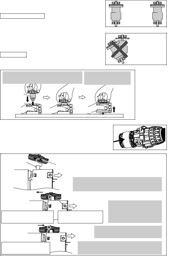
Caution for Handling of Rotor
When handling or storing multiple Rotors, be sure to keep a proper distance between Rotors as shown in Fig. 13
because Rotor is a strong magnet, failure to follow this instruction could result in:
•Finger injury caused by pinching between Rotors pulling each other
•Magnetic loss of Rotors or damage on the magnet portion of Rotor. (Fig. 14)
ASSEMBLING
(1) Put Rotor into Stator complete as drawn in Fig. 15.
Fig. 15
P 4/ 11
Fig. 13
Fig. 14


 * Magnetic loss of Rotors
* Damage on the magnet portion of Rotor
1.Holding Stator complete on a workbench, insert Rotor slowly in Stator complete until Rotor’s drive end reaches the workbench.
2.When the drive end of Rotor reaches the workbench, lift up Stator complete slowly.
Rotor
Stator complete
Fig. 16
(2) Make sure that Rotor’s gear engages with the super gears of Gear assembly to rotate them smoothly, and push Rotor section (Rotor and Stator) fully in Gear assembly, (Fig. 16)
(3) Assemble Speed change lever assembly as drawn in Fig. 17.
Fig. 17
Pin on the lever of Gear assembly
front Compression spring 4 |
Stator 

 Gear
Gear
assembly
Drill chuck
side 1. Apply the front Compression spring 4 of Speed change lever assembly to the flat side (without pin) of Gear assembly
for Speed change.
Space between the rear Compression spring 4 and the pin on the lever of Gear assembly
Pin on the lever of Gear assembly for fitting into the coil of the rear Compression spring 4.
Drill chuck |
2. Push Speed change lever assembly |
|
side |
toward Rotor side until it stops to |
|
The front Compression spring 4 |
have space between the pin of |
|
Gear assembly and the rear |
||
compressed by the lever of |
||
Compression spring 4. |
||
Gear assembly. |
||
|
3. Fit the pin of Gear assembly to Spring’s coil
with slowly returning Speed change lever Drill chuck assembly toward Drill chuck side.
side
4. Slide Speed change lever assembly to High speed mode: (Position 2 shown on Housing: Refer to Fig. 20 in
the next page.)
 Loading...