


|
EN |
Cordless Grass Trimmer |
INSTRUCTION MANUAL |
13 |
|
|
|
|
|
|
|
Coupe herbe sans fil |
MANUEL D’INSTRUCTIONS |
26 |
|
FR |
|||
|
|
|
|
|
|
|
Akku-Rasentrimmer |
BETRIEBSANLEITUNG |
40 |
|
DE |
|||
|
|
|
|
|
|
|
Tagliabordi a batteria |
ISTRUZIONI PER L’USO |
55 |
|
IT |
|||
|
|
|
|
|
|
|
Accugrastrimmer |
GEBRUIKSAANWIJZING |
70 |
|
NL |
|||
|
|
|
|
|
|
|
Cortador Inalámbrico de |
MANUAL DE |
84 |
|
ES |
|||
|
Pasto |
INSTRUCCIONES |
||
|
|
|
||
|
|
TESOURA PARA GRAMA A |
MANUAL DE INSTRUÇÕES |
99 |
|
PT |
|||
|
BATERIA |
|||
|
|
|
|
|
|
|
Akku græstrimmer |
BRUGSANVISNING |
113 |
|
DA |
|||
|
|
|
|
|
|
|
Φορητό κουρευτικό γκαζόν |
ΕΓΧΕΙΡΙΔΙΟ ΟΔΗΓΙΩΝ |
126 |
|
EL |
|||
|
|
|
|
|
|
|
Akülü Yan Tırpan |
KULLANMA KILAVUZU |
141 |
|
TR |
|||
|
|
|
|
|
DUR368A
DUR368L
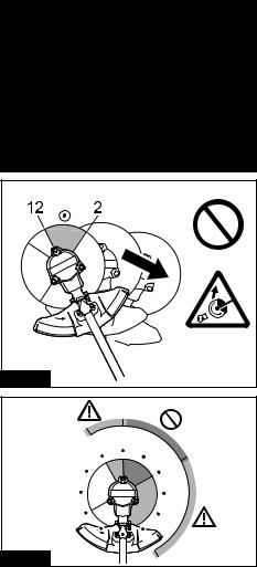
Fig.1 |
|
Fig.2 |
|
11 |
12 |
1 |
|
10 |
2 |
9 |
3 |
8 |
4 |
|
5 |
Fig.3 |
|
2

|
DUR368L |
|
|
|
6 |
|
|
|
1 |
2 |
|
|
7 |
3 |
DUR368A |
|
8 |
||
|
4 |
5 |
6 |
|
9 |
|
|
|
|
|
|
10 |
|
7 |
|
|
|
|
|
|
11 |
9 |
|
|
|
8 |
|
|
|
|
10 |
12 |
13 |
|
|
|
12 |
|
13 |
|
14 |
|
|
Fig.4 |
|
|
|
2 |
|
|
|
|
3 |
|
1 |
1 |
|
|
|
|
|
|
|
|
|
|
2 |
Fig.5 |
Fig.6 |
|
|
|
3 |
|
|
|
1 |
2 |
3 |
|
|
Fig.7 |
|
2 |
1 |
|
|
Fig.8 |
|
1 |
2 |
Fig.9 |
1 |
2 |
Fig.10
1 |
3 |
|
2 |
||
|
||
4 |
5 |
|
Fig.11 |
|
|
2 |
|
1 |
Fig.12 |
|
1 |
|
2 |
|
Fig.13 |
3 |
|
|
|
1 |
|
2 |
Fig.14 |
3 |
|
4
1 |
|
2 |
|
3 |
6 |
|
4 |
Fig.15 |
5 |
|
1 |
Fig.16 |
2 |
|
1 |
Fig.17 |
1 |
Fig.18 |
|
1 |
|
2 |
Fig.19 |
|
|
1 |
|
2 |
Fig.20 |
3 |
|
1 |
|
2 |
|
3 |
|
4 |
|
5 |
|
6 |
Fig.21 |
|
|
1 |
|
1 |
Fig.22 |
|
5

|
|
3 |
2 |
4 |
1 |
|
||
|
|
|
Fig.23 |
|
|
6 |
|
1 |
5 |
|
4 |
2 |
|
|
|
|
|
3 |
|
|
Fig.24 |
|
|
6 |
|
1 |
5 |
|
4 |
2 |
|
|
3 |
|
|
Fig.25 |
|
|
Fig.26 |
|
|
|
|
6 |
2 |
1 |
Fig.27 |
2 |
1 |
Fig.28 |
Fig.29 |
1 |
Fig.30

1 |
|
Fig.31 |
Fig.35 |
1 |
750 mm |
2 |
|
|
100-300 mm |
|
750 mm |
|
Fig.32 |
3 |
Fig.36 |
|
1 |
1 |
|
|
|
2 |
Fig.33 |
Fig.37 |
|
1 |
|
2 |
Fig.34 |
|
7

3 m
100 mm
80 mm
Fig.38
8

3 m
100 mm
80 mm
Fig.39
9
3 m
100 mm
80 mm
Fig.40
10
4.5 m
100 mm
Fig.41
11

0.75 m |
x 2 |
1 mm |
150 mm |
Fig.42 |
12 |
Fig.43 |
1 |
2 |
Fig.44 |

ENGLISH (Original instructions)
SPECIFICATIONS
Model: |
|
DUR368A |
|
DUR368L |
Handle type |
|
Bike handle |
|
Loop handle |
No load speed |
Cutter blade / Nylon cutting |
|
3: 6,500 min-1 |
|
(at each rotation speed level) |
head / Plastic blade |
|
2: 5,300 min-1 |
|
|
|
|
1: 3,500 min-1 |
|
Overall length |
|
|
1,758 mm |
|
(without cutting tool) |
|
|
|
|
Nylon cord diameter |
|
|
2.0 - 2.4 mm |
|
Applicable cutting tool and |
3-tooth blade |
|
230 mm |
|
cutting diameter |
(P/N: 195298-3) |
|
|
|
|
4-tooth blade |
|
230 mm |
|
|
(P/N: B-14118) |
|
|
|
|
8-tooth blade |
|
230 mm |
|
|
(P/N: B-14130) |
|
|
|
|
Nylon cutting head |
|
350 mm |
|
|
(P/N: 198893-8) |
|
|
|
|
Plastic blade |
|
255 mm |
|
|
(P/N: 198383-1) |
|
|
|
Rated voltage |
|
|
D.C. 36 V |
|
Net weight |
|
4.1 - 4.7 kg |
|
3.9 - 4.5 kg |
•Due to our continuing program of research and development, the specifications herein are subject to change without notice.
•Specifications may differ from country to country.
•The weight may differ depending on the attachment(s), including the battery cartridge. The lightest and heaviest combination, according to EPTA-Procedure 01/2014, are shown in the table.
Applicable battery cartridge, battery adapter and charger
Battery cartridge |
BL1815N / BL1820 / BL1820B / BL1830 / BL1830B / BL1840 / |
|
BL1840B / BL1850 / BL1850B / BL1860B |
Battery Adapter |
BAP182 / BL36120A |
Charger |
DC18RC / DC18RD / DC18RE / DC18SD / DC18SE / DC18SF / DC18SH |
•Some of the battery cartridges, battery adapters and chargers listed above may not be available depending on your region of residence.
 WARNING: Only use the battery cartridges, battery adapters and chargers listed above. Use of any other battery cartridges,battery adapters and chargers may cause injury and/or fire.
Noise
Applicable standard : ISO22868
Model DUR368A
Cutting tool |
Sound pressure level (LpA) |
Sound power level (LWA) |
||||
|
|
dB(A) |
|
dB(A) |
||
|
LpA dB(A) |
|
Uncertainty (K) |
LWA dB(A) |
|
Uncertainty (K) |
|
|
|
dB(A) |
|
|
dB(A) |
4-tooth blade |
74.7 |
|
1.0 |
89.2 |
|
1.6 |
Nylon cutting head |
76.4 |
|
1.6 |
89 |
|
1.0 |
Plastic blade |
75.1 |
|
0.3 |
86 |
|
0.4 |
13 ENGLISH

Model DUR368L
Cutting tool |
Sound pressure level (LpA) |
Sound power level (LWA) |
||||
|
|
dB(A) |
|
dB(A) |
||
|
LpA dB(A) |
|
Uncertainty (K) |
LWA dB(A) |
|
Uncertainty (K) |
|
|
|
dB(A) |
|
|
dB(A) |
4-tooth blade |
74.7 |
|
1.0 |
89.2 |
|
1.6 |
Nylon cutting head |
76.4 |
|
1.6 |
89 |
|
1.0 |
Plastic blade |
75.1 |
|
0.3 |
86 |
|
0.4 |
•Even if the sound pressure level listed above is 80 dB (A) or less, the level under working may exceed 80 dB
(A). Wear ear protection.
NOTE: The declared noise emission value(s) has been measured in accordance with a standard test method and may be used for comparing one tool with another.
NOTE: The declared noise emission value(s) may also be used in a preliminary assessment of exposure.
 WARNING: Wear ear protection.
 WARNING: The noise emission during actual use of the power tool can differ from the declared value(s) depending on the ways in which the tool is used especially what kind of workpiece is processed.
 WARNING: Be sure to identify safety measures to protect the operator that are based on an estimation of exposure in the actual conditions of use (taking account of all parts of the operating cycle such as the times when the tool is switched off and when it is running idle in addition to the trigger time).
Vibration
Applicable standard : ISO22867
Model DUR368A
Cutting tool |
Left hand |
Right hand |
||
|
ah,W (m/s2) |
Uncertainty K |
ah,W (m/s2) |
Uncertainty K |
|
|
(m/s2) |
|
(m/s2) |
4-tooth blade |
2.5 |
1.5 |
2.5 |
1.5 |
|
|
|
||
Nylon cutting head |
2.5 |
1.5 |
2.5 |
1.5 |
|
|
|
||
Plastic blade |
2.5 |
1.5 |
2.5 |
1.5 |
|
|
|
||
Model DUR368L |
|
|
|
|
|
|
|
||
Cutting tool |
Left hand |
Right hand |
||
|
ah,W (m/s2) |
Uncertainty K |
ah,W (m/s2) |
Uncertainty K |
|
|
(m/s2) |
|
(m/s2) |
4-tooth blade |
2.5 |
1.5 |
2.5 |
1.5 |
|
|
|
||
Nylon cutting head |
2.5 |
1.5 |
2.5 |
1.5 |
|
|
|
||
Plastic blade |
2.5 |
1.5 |
2.5 |
1.5 |
|
|
|
||
NOTE: The declared vibration total value(s) has been measured in accordance with a standard test method and may be used for comparing one tool with another.
NOTE: The declared vibration total value(s) may also be used in a preliminary assessment of exposure.
 WARNING: The vibration emission during actual use of the power tool can differ from the declared value(s) depending on the ways in which the tool is used especially what kind of workpiece is processed.
 WARNING: Be sure to identify safety measures to protect the operator that are based on an estimation of exposure in the actual conditions of use (taking account of all parts of the operating cycle such as the times when the tool is switched off and when it is running idle in addition to the trigger time).
14 ENGLISH

Symbols
The followings show the symbols used for the equipment. Be sure that you understand their meaning before use.
|
|
Take particular care and attention. |
|
|
|
|
|
Read instruction manual. |
|
|
|
|
|
|
15m(50FT) |
Keep distance at least 15 m. |
|
|
||
|
|
|
|
|
Danger; be aware of thrown objects. |
|
|
|
|
|
Caution; kickback |
|
|
|
|
|
Wear a helmet, goggles and ear protection. |
|
|
|
|
|
Wear protective gloves. |
|
|
|
|
|
Wear sturdy boots with nonslip soles. |
|
|
Steeltoed safety boots are recommended. |
|
|
|
|
|
Do not expose to moisture. |
|
|
|
Ni-MH |
Only for EU countries |
|
Li-ion |
Do not dispose of electric equipment or |
|
|
|
battery pack together with household |
|
|
waste material! In observance of the |
|
|
European Directives, on Waste Electric |
|
|
and Electronic Equipment and Batteries |
|
|
and Accumulators and Waste Batteries and |
|
|
Accumulators and their implementation |
|
|
in accordance with national laws, electric |
|
|
equipment and batteries and battery |
|
|
pack(s) that have reached the end of |
|
|
their life must be collected separately and |
|
|
returned to an environmentally compatible |
|
|
recycling facility. |
EC Declaration of Conformity
For European countries only
The EC declaration of conformity is included as Annex A to this instruction manual.
SAFETY WARNINGS
General power tool safety warnings
 WARNING: Read all safety warnings, instructions, illustrations and specifications provided with this power tool. Failure to follow all instructions listed below may result in electric shock, fire and/or serious injury.
Save all warnings and instructions for future reference.
The term "power tool" in the warnings refers to your mains-operated (corded) power tool or battery-operated (cordless) power tool.
Important safety instructions for the tool
 WARNING: Read all safety warnings and all instructions. Failure to follow the warnings and instructions may result in electric shock, fire and/or serious injury.
Save all warnings and instructions for future reference.
Intended use
1.This tool is only intended for cutting grass, weeds, bushes and undergrowth. It should not be used for any other purpose such as edging or hedge cutting as this may cause injury.
General instructions
1.Never allow people unfamiliar with these instructions, people (including children) with reduced physical, sensory or mental capabilities, or lack of experience and knowledge to use the tool. Children should be supervised to ensure that they do not play with the tool.
2.Before starting the tool, read this instruction manual to become familiar with the handling of the tool.
3.Do not lend the tool to a person with insufficient experience or knowledge regarding handling of brushcutters and string trimmers.
4.When lending the tool, always attach this instruction manual.
5.Handle the tool with the utmost care and attention.
6.Never use the tool after consuming alcohol or drugs, or if feeling tired or ill.
7.Never attempt to modify the tool.
8.Follow the regulations about handling of brushcutters and string trimmers in your country.
Personal protective equipment
► Fig.1
1.Wear safety helmet, protective goggles and protective gloves to protect yourself from flying debris or falling objects.
2.Wear ear protection such as ear muffs to prevent hearing loss.
3.Wear proper clothing and shoes for safe operation, such as a work overall and sturdy, non-slip shoes. Do not wear loose clothing or jewelry. Loose clothes, jewelry or long hair can be caught in moving parts.
4.When touching the cutting blade, wear protective gloves. Cutting blades can cut bare hands severely.
15 ENGLISH
Work area safety
1.Operate the tool under good visibility and daylight conditions only. Do not operate the tool in darkness or fog.
2.Do not operate the tool in explosive atmospheres, such as in the presence of flammable liquids, gases or dust. The tool creates sparks which may ignite the dust or fumes.
3.During operation, never stand on an unstable or slippery surface or a steep slope. During the cold season, beware of ice and snow and always ensure secure footing.
4.During operation, keep bystanders or animals at least 15 m away from the tool. Stop the tool as soon as someone approaches.
5.Never operate the tool while people, especially children, or pets are nearby.
6.Before operation, examine the work area for stones or other solid objects. They can be thrown or cause dangerous kickback and result in serious injury and/or property damage.
7. WARNING: Use of this product can create dust containing chemicals which may cause respiratory or other illnesses. Some examples of these chemicals are compounds found in pesticides, insecticides, fertilizers and herbicides. Your risk from these exposures varies, depending on how often you do this type
of work. To reduce your exposure to these chemicals: work in a well ventilated area, and work with approved safety equipment, such as those dust masks that are specially designed to filter out microscopic particles.
Electrical and battery safety
1.Do not expose the tool to rain or wet conditions. Water entering the tool will increase the risk of electric shock.
2.Do not use the tool if the switch does not turn it on and off. Any tool that cannot be controlled with the switch is dangerous and must be repaired.
3.Prevent unintentional starting. Ensure the switch is in the off-position before installing a battery pack, picking up or carrying the tool.
Carrying the tool with your finger on the switch or energising the tool that have the switch on invites accidents.
4.Do not dispose of the battery(ies) in a fire.
The cell may explode. Check with local codes for possible special disposal instructions.
5.Do not open or mutilate the battery(ies).
Released electrolyte is corrosive and may cause damage to the eyes or skin. It may be toxic if swallowed.
6.Do not charge battery in rain, or in wet locations.
Putting into operation
1.Before assembling or adjusting the tool, remove the battery cartridge.
2.Before handling the cutter blade, wear protective gloves.
3.Before installing the battery cartridge, inspect the tool for damages, loose screws/nuts or improper assembly. Sharpen blunt cutter blade. If the cutter blade is bent or damaged, replace it. Check all control levers and switches for easy action. Clean and dry the handles.
4.Never attempt to switch on the tool if it is damaged or not fully assembled. Otherwise serious injury may result.
5.Adjust the shoulder harness and hand grip to suit the operator's body size.
6.When inserting a battery cartridge, keep the cutting attachment clear of your body and other object, including the ground. It may rotate when starting and may cause injury or damage to the tool and/or property.
7.Remove any adjusting key, wrench or blade cover before turning the tool on. An accessory left attached to a rotating part of the tool may result in personal injury.
8.The cutting tool has to be equipped with the guard. Never run the tool with damaged guards or without guards in place!
9.Make sure there are no electrical cables, water pipes, gas pipes etc. that could cause a hazard if damaged by use of the tool.
Operation
1.In the event of an emergency, switch off the tool immediately.
2.If you feel any unusual condition (e.g. noise, vibration) during operation, switch off the tool and remove the battery cartridge. Do not use the tool until the cause is recognized and solved.
3.The cutting attachment continues to rotate for a short period after turning the tool off. Don't rush to contact the cutting attachment.
4.During operation, use the shoulder harness.
Keep the tool on your right side firmly.
5.Do not overreach. Keep proper footing and balance at all times. Watch for hidden obstacles such as tree stumps, roots and ditches to avoid stumbling.
6.Always be sure of your footing on slopes.
7.Walk, never run.
8.Never work on a ladder or tree to avoid loss of control.
9.If the tool gets heavy impact or fall, check the condition before continuing work. Check the controls and safety devices for malfunction. If there is any damage or doubt, ask our authorized service center for the inspection and repair.
10.Take a rest to prevent loss of control caused by fatigue. We recommend taking a 10 to 20-min- ute rest every hour.
11.When you leave the tool, even if it is a short time, always remove the battery cartridge. The unattended tool with the battery cartridge installed may be used by unauthorized person and cause serious accident.
16 ENGLISH
12.If grass or branches get caught between the cutting attachment and guard, always turn the tool off and remove the battery cartridge before cleaning. Otherwise the cutting attach-
ment may rotate unintentionally and cause serious injury.
13.Never touch moving hazardous parts before the moving hazardous parts have come to a complete stop and the battery cartridge is removed.
14.If the cutting attachment hits stones or other hard objects, immediately turn the tool off. Then remove the battery cartridge and inspect the cutting attachment.
15.Check the cutting attachment frequently during operation for cracks or damages. Before the inspection, remove the battery cartridge and wait until the cutting attachment stops completely. Replace damaged cutting attachment immediately, even if it has only superficial cracks.
16.Never cut above waist height.
17.Before starting the cutting operation, wait until the cutting attachment reaches a constant speed after turning the tool on.
18.When using a cutting blade, swing the tool evenly in half-circle from right to left, like using a scythe.
19.Hold the tool by insulated gripping surfaces only, because the cutter blade may contact hidden wiring. Cutter blades contacting a "live" wire may make exposed metal parts of the tool "live" and could give the operator an electric shock.
20.Do not start the tool when the cutting tool is tangled with cut grass.
21.Before starting the tool, be sure that the cutting tool is not touching the ground and other obstacles such as a tree.
22.During operation always hold the tool with both hands. Never hold the tool with one hand during use.
Cutting tools
1.Do not use a cutting tool which is not recommended by us.
2.Use an applicable cutting attachment for the job in hand.
—Nylon cutting heads (string trimmer heads) and plastic blades are suitable for trimming lawn grass.
—Cutting blades are suitable for cutting weeds, high grasses, bushes, shrubs, underwood, thicket, and the like.
—Never use other blades including metal multi-piece pivoting chains and flail blades. It may result in serious injury.
3.Only use the cutting tool that are marked with a speed equal or higher than the speed marked on the tool.
4.Always keep your hands, face, and clothes away from the cutting tool when it is rotating.
Failure to do so may cause personal injury.
5.Always use the cutting attachment guard properly suited for the cutting attachment used.
6.When using cutting blades, avoid kickback and always prepare for an accidental kickback. See the section for Kickback.
7.When not in use, attach the blade cover onto the blade. Remove the cover before operation.
Kickback (Blade thrust)
1.Kickback (blade thrust) is a sudden reaction to a caught or bound cutting blade. Once it occurs, the tool is thrown sideway or toward the operator at great force and it may cause serious injury.
2.Kickback occurs particularly when applying the blade segment between 12 and 2 o'clock to solids, bushes and trees with 3 cm or larger diameter.
► Fig.2
3.To avoid kickback:
1.Apply the segment between 8 and 11 o'clock.
2.Never apply the segment between 12 and 2 o'clock.
3.Never apply the segment between 11 and 12 o'clock and between 2 and 5 o'clock, unless the operator is well trained and experienced and does it at his/her own risk.
4.Never use cutting blades close to solids, such as fences, walls, tree trunks and stones.
5.Never use cutting blades vertically, for such operations as edging and trimming hedges.
►Fig.3
Vibration
1.People with poor circulation who are exposed to excessive vibration may experience injury to blood vessels or the nervous system.
Vibration may cause the following symptoms to occur in the fingers, hands or wrists: "Falling
asleep" (numbness), tingling, pain, stabbing sensation, alteration of skin color or of the skin. If any of these symptoms occur, see a physician!
2.To reduce the risk of "white finger disease", keep your hands warm during operation and well maintain the tool and accessories.
Transport
1.Before transporting the tool, turn it off and remove the battery cartridge. Attach the cover to the cutting blade.
2.When transporting the tool, carry it in a horizontal position by holding the shaft.
3.When transporting the tool in a vehicle, properly secure it to avoid turnover. Otherwise damage to the tool and other baggage may result.
17 ENGLISH

Maintenance
1.Have your tool serviced by our authorized service center, always using only genuine replacement parts. Incorrect repair and poor maintenance can shorten the life of the tool and increase the risk of accidents.
2.Before doing any maintenance or repair work or cleaning the tool, always turn it off and remove the battery cartridge.
3.Always wear protective gloves when handling the cutting blade.
4.Always clean dust and dirt off the tool. Never use gasoline, benzine, thinner, alcohol or the like for the purpose. Discoloration, deformation or cracks of the plastic components may result.
5.After each use, tighten all screws and nuts.
6.Do not attempt any maintenance or repair not described in the instruction manual. Ask our authorized service center for such work.
7.Always use our genuine spare parts and accessories only. Using parts or accessories supplied by a third party may result in the tool breakdown, property damage and/or serious injury.
8.Request our authorized service center to inspect and maintain the tool at regular interval.
9.Always keep the tool in good working condition. Poor maintenance can result in inferior performance and shorten the life of the tool.
Storage
1.Before storing the tool, perform full cleaning and maintenance. Remove the battery cartridge. Attach the cover to the cutting blade.
2.Store the tool in a dry and high or locked location out of reach of children.
3.Do not prop the tool against something, such as a wall. Otherwise it may fall suddenly and cause an injury.
First aid
1.Always have a first-aid kit close by.
Immediately replace any item taken from the first aid kit.
2.When asking for help, give the following information:
—Place of the accident
—What happened
—Number of injured persons
—Nature of the injury
—Your name
SAVE THESE INSTRUCTIONS.
 WARNING: DO NOT let comfort or familiarity with product (gained from repeated use) replace strict adherence to safety rules for the subject product. MISUSE or failure to follow the safety rules stated in this instruction manual may cause serious personal injury.
Important safety instructions for battery cartridge
1.Before using battery cartridge, read all instructions and cautionary markings on (1) battery charger, (2) battery, and (3) product using battery.
2.Do not disassemble battery cartridge.
3.If operating time has become excessively shorter, stop operating immediately. It may result in a risk of overheating, possible burns and even an explosion.
4.If electrolyte gets into your eyes, rinse them out with clear water and seek medical attention right away. It may result in loss of your eyesight.
5.Do not short the battery cartridge:
(1)Do not touch the terminals with any conductive material.
(2)Avoid storing battery cartridge in a container with other metal objects such as nails, coins, etc.
(3)Do not expose battery cartridge to water or rain.
A battery short can cause a large current flow, overheating, possible burns and even a breakdown.
6.Do not store the tool and battery cartridge in locations where the temperature may reach or exceed 50 °C (122 °F).
7.Do not incinerate the battery cartridge even if it is severely damaged or is completely worn out. The battery cartridge can explode in a fire.
8.Be careful not to drop or strike battery.
9.Do not use a damaged battery.
10.The contained lithium-ion batteries are subject to the Dangerous Goods Legislation requirements.
For commercial transports e.g. by third parties, forwarding agents, special requirement on packaging and labeling must be observed.
For preparation of the item being shipped, consulting an expert for hazardous material is required.
Please also observe possibly more detailed national regulations.
Tape or mask off open contacts and pack up the battery in such a manner that it cannot move around in the packaging.
11.When disposing the battery cartridge, remove it from the tool and dispose of it in a safe place. Follow your local regulations relating to disposal of battery.
12.Use the batteries only with the products specified by Makita. Installing the batteries to non-compliant products may result in a fire, excessive heat, explosion, or leak of electrolyte.
13.If the tool is not used for a long period of time, the battery must be removed from the tool.
SAVE THESE INSTRUCTIONS.
 CAUTION: Only use genuine Makita batteries.
Use of non-genuine Makita batteries, or batteries that have been altered, may result in the battery bursting causing fires, personal injury and damage. It will also void the Makita warranty for the Makita tool and charger.
18 ENGLISH

Tips for maintaining maximum battery life
1.Charge the battery cartridge before completely discharged. Always stop tool operation and charge the battery cartridge when you notice less tool power.
2.Never recharge a fully charged battery cartridge. Overcharging shortens the battery service life.
3.Charge the battery cartridge with room temperature at 10 °C - 40 °C (50 °F - 104 °F). Let a hot battery cartridge cool down before charging it.
4.Charge the battery cartridge if you do not use it for a long period (more than six months).
PARTS DESCRIPTION
► Fig.4
1 |
Speed indicator |
2 |
ADT indicator |
3 |
Power lamp |
4 |
Main power button |
|
|
|
(ADT =Automatic Torque |
|
|
|
|
|
|
|
Drive Technology) |
|
|
|
|
5 |
Reverse button |
6 |
Battery cartridge |
7 |
Lock-off lever |
8 |
Switch trigger |
9 |
Hanger |
10 |
Handle |
11 |
Barrier (country specific) |
12 |
Protector (for nylon |
|
|
|
|
|
|
|
cutting head / plastic |
|
|
|
|
|
|
|
blade) |
13 |
Protector (for cutter |
14 |
Shoulder harness |
- |
- |
- |
- |
|
blade) |
|
|
|
|
|
|
NOTE: The protector supplied as the standard accessory varies depending on the countries.
FUNCTIONAL
DESCRIPTION
 WARNING: Always be sure that the tool is switched off and the battery cartridge is removed before adjusting or checking function on the tool.
Failure to switch off and remove the battery cartridge may result in serious personal injury from accidental start-up.
Installing or removing battery cartridge
 CAUTION: Always switch off the tool before installing or removing of the battery cartridge.
 CAUTION: Hold the tool and the battery cartridge firmly when installing or removing battery cartridge. Failure to hold the tool and the battery cartridge firmly may cause them to slip off your hands and result in damage to the tool and battery cartridge and a personal injury.
► Fig.5: 1. Red indicator 2. Button 3. Battery cartridge
To remove the battery cartridge, slide it from the tool while sliding the button on the front of the cartridge.
To install the battery cartridge, align the tongue on the battery cartridge with the groove in the housing and slip it into place. Insert it all the way until it locks in place with a little click. If you can see the red indicator on the upper side of the button, it is not locked completely.
 CAUTION: Always install the battery cartridge fully until the red indicator cannot be seen. If not, it may accidentally fall out of the tool, causing injury to you or someone around you.
 CAUTION: Do not install the battery cartridge forcibly. If the cartridge does not slide in easily, it is not being inserted correctly.
Tool / battery protection system
The tool is equipped with a tool/battery protection system. This system automatically cuts off power to the motor to extend tool and battery life. The tool will automatically stop during operation if the tool or battery is placed under one of the following conditions:
Status |
|
Speed indicator |
|
|
On |
Off |
Blinking |
Overload |
|
|
|
Overheat |
3 |
3 |
|
|
|
||
|
2 |
2 |
|
Over |
|
3 |
|
discharge |
|
|
|
|
|
2 |
|
19 ENGLISH

Overload protection
If the tool is overloaded by entangled weeds or other debris, the speed indicator 2 and 3 start blinking and the tool automatically stops.
In this situation, turn the tool off and stop the application that caused the tool to become overloaded. Then turn the tool on to restart.
Overheat protection for tool or battery
There are two types of overheating; tool overheating and battery overheating. When the tool overheating occurs, all speed indicators blink. When the battery overheating occurs, the speed indicator 1 blinks.
If the overheating occurs, the tool stops automatically. Let the tool and/or battery cool down before turning the tool on again.
Overdischarge protection
When the battery capacity becomes low, the tool stops automatically and the speed indicator 1 blinks.
If the tool does not operate even when the switches are operated, remove the batteries from the tool and charge the batteries.
Indicating the remaining battery capacity
Only for battery cartridges with the indicator
► Fig.6: 1. Indicator lamps 2. Check button
Press the check button on the battery cartridge to indicate the remaining battery capacity. The indicator lamps light up for a few seconds.
|
Indicator lamps |
Remaining |
|
|
capacity |
Lighted |
Off |
Blinking |
|
|
75% to 100% |
|
|
50% to 75% |
|
|
25% to 50% |
|
|
0% to 25% |
|
|
Charge the |
|
|
battery. |
|
|
The battery |
|
|
may have |
|
|
malfunctioned. |
NOTE: Depending on the conditions of use and the ambient temperature, the indication may differ slightly from the actual capacity.
Main power switch
Tap the main power button to turn on the tool.
To turn off the tool, press and hold the main power button until the power lamp and speed indicator go off.
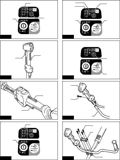
►Fig.7: 1. Speed indicator 2. Main power button
3.Power lamp
NOTE: The tool will automatically turned off if it is left without any operations for a certain period of time.
Switch action
 WARNING: For your safety, this tool is equipped with lock-off lever which prevents the tool from unintended starting. NEVER use the tool if it runs when you simply pull the switch trigger without pressing the lock-off lever. Return the tool to our authorized service center for proper repairs BEFORE further usage.
 WARNING: NEVER tape down or defeat purpose and function of lock-off lever.
 CAUTION: Before installing the battery cartridge into the tool, always check to see that the switch trigger actuates properly and returns to the "OFF" position when released. Operating a tool with a switch that does not actuate properly can lead to loss of control and serious personal injury.
 CAUTION: Never put your finger on the main power button and switch trigger when carrying the tool. The tool may start unintentionally and cause injury.
NOTICE: Do not pull the switch trigger hard without pressing the lock-off lever. This can cause switch breakage.
To prevent the switch trigger from being accidentally pulled, a lock-off lever is provided. To start the tool, depress the lock-off lever and pull the switch trigger.
The tool speed increases by increasing pressure on the switch trigger. Release the switch trigger to stop.
DUR368A
► Fig.8: 1. Lock-off lever 2. Switch trigger
DUR368L
► Fig.9: 1. Lock-off lever 2. Switch trigger
Speed adjusting
You can adjust the tool speed by tapping the main power button. Each time you tap the main power button, the level of speed will change.
► Fig.10: 1. Speed indicator 2. Main power button
Speed indicator |
Mode |
Rotation speed |
|
High |
6,500 min-1 |
|
|
|
|
Medium |
5,300 min-1 |
|
|
|
|
Low |
3,500 min-1 |
|
|
|
20 ENGLISH
Automatic Torque Drive Technology
When you turn on the Automatic Torque Drive Technology (ADT), the tool runs at optimum rotation speed and torque for the condition of grass being cut.
To start ADT, press and hold the reverse button until the ADT indicator turns on. After that, tap the main power button to select the cutting tool attached to the tool. Light
the lamp beside  marking to select cutter blade and
plastic blade,  marking to select nylon cutting head.
To stop ADT, press and hold the reverse button until the ADT indicator turns off.
► Fig.11: 1.  marking 2.
  marking 3. ADT indicator 4. Main power button 5. Reverse button
|
Indicator |
Mode |
Cutting tool |
Rotation |
|
|
|
|
speed |
|
|
ADT |
Cutter blade |
3,500 - 6,500 |
|
|
(Cutter blade) |
Plastic blade |
min-1 |
|
|
|||
|
|
|||
|
|
|
|
|
|
|
ADT |
Nylon cutting |
3,500 - 6,500 |
|
|
(Nylon cutting |
head |
min-1 |
|
|
|||
|
|
|||
|
|
head) |
|
|
|
|
|
|
|
Reverse button for debris removal
 WARNING: Switch off the tool and remove the battery cartridge before you remove entangled weeds or debris which the reverse rotation function can not remove. Failure to switch off and remove the battery cartridge may result in serious personal injury from accidental start-up.
This tool has a reverse button to change the direction of rotation. It is only for removing weeds and debris entangled in the tool. To reverse the rotation, tap the reverse button and pull the trigger when the cutting tool is stopped. The power lamp starts blinking, and the cutting tool rotates in reverse direction when you pull the switch trigger.
To return to regular rotation, release the trigger and wait until the cutting tool stops.
► Fig.12: 1. Reverse button 2. Power lamp
NOTE: During the reverse rotation, the tool operates only for a short period of time and then automatically stops.
NOTE: Once the tool is stopped, the rotation returns to regular direction when you start the tool again.
NOTE: If you tap the reverse button while the cutting tool is still rotating, the tool comes to stop and to be ready for reverse rotation.
Electric brake
This tool is equipped with an electric brake for the cutting tool. If the tool consistently fails to quickly stop the cutting tool after the switch trigger is released, have the tool serviced at our service center.
 CAUTION: This brake system is not a substitute for the protector. Never use the tool without the protector. An unguarded cutting tool may result in serious personal injury.
Electronic function
Constant speed control
The speed control function provides the constant rotation speed regardless of load conditions.
Soft start feature
Soft start because of suppressed starting shock.
ASSEMBLY
 WARNING: Always be sure that the tool is switched off and battery cartridge is removed before carrying out any work on the tool. Failure to switch off and remove the battery cartridge may result in serious personal injury from accidental start-up.
 WARNING: Never start the tool unless it is completely assembled. Operation of the tool in a partially assembled state may result in serious personal injury from accidental start-up.
Installing the handle
For DUR368A
1. Insert the shaft of the handle into the grip. Align the screw hole in the grip with the one in the shaft. Tighten the screw securely.
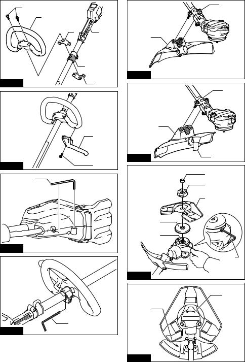
► Fig.13: 1. Grip 2. Screw 3. Shaft
NOTICE: Note the direction of the grip. The screw holes will not be aligned if the grip is not inserted in the correct direction.
2. Place handle between handle clamp and handle holder.
Adjust the handle to an angle that provides a comfortable working position and then secure with hex socket head bolts.
►Fig.14: 1. Hex socket head bolt 2. Handle clamp
3.Handle holder
For DUR368L
1.Attach the upper and lower clamps on the damper.
2.Put the handle on the upper clamp and fix it with hex socket head bolts as illustrated.
► Fig.15: 1. Hex socket head bolt 2. Handle 3. Upper clamp 4. Damper 5. Lower clamp 6. Spacer
 CAUTION: Do not remove or shrink the spacer. Doing so lose the balance of the tool and may cause personal injury.
Attaching the barrier
Country specific
If the barrier is included in your model, attach it to the handle using the screw on the barrier.
► Fig.16: 1. Barrier 2. Screw
 CAUTION: After assembling the barrier, do not remove it. The barrier works as a safety part to prevent you from contacting the cutting blade accidentally.
21 ENGLISH

Hex wrench storage
 CAUTION: Be careful not to leave the hex wrench inserted in the tool head. It may cause injury and/or damage to the tool.
When not in use, store the hex wrench as illustrated to keep it from being lost.
► Fig.17: 1. Hex wrench
For the loop handle model, the hex wrench can also be stored on the handle as illustrated.
► Fig.18: 1. Hex wrench
Correct combination of the cutting tool and the protector
 CAUTION: Always use the correct combination of cutting tool and the protector. A wrong combination may not protect you from the cutting tool, flying debris, and stones. It can also affect the balance of the tool and result in an injury.
Cutting tool |
Protector |
Cutter blade
(3-tooth, 4-tooth, and 8-tooth blades)
Nylon cutting head
Plastic blade
Installing the protector
 WARNING: Never use the tool without the guard illustrated in place. Failure to do so can cause serious personal injury.
NOTE: The type of the protector supplied as the standard accessory varies depending on the countries.
For cutter blade
Attach the protector to the clamp using bolts. ► Fig.19: 1. Clamp 2. Protector
For nylon cutting head / plastic blade
 CAUTION: Take care not to injure yourself on the cutter for cutting the nylon cord.
Attach the protector to the clamp using bolts. ► Fig.20: 1. Clamp 2. Protector 3. Cutter
Installing the cutting tool
 CAUTION: Always use the supplied wrench(es) to remove or to install the cutting tool.
 CAUTION: Be sure to remove the hex wrench inserted into the tool head after installing the cutting tool.
NOTE: The type of the cutting tool(s) supplied as the standard accessory varies depending on the countires. The cutting tool is not included in some specifications of the model.
NOTE: Turn the tool upside down so that you can replace the cutting tool easily.
Cutter blade
 CAUTION: When handling the cutter blade, always wear gloves and put the blade cover on the blade.
 CAUTION: The cutter blade must be well polished, and free of cracks or breakage. If the cutter blade hits a stone during operation, stop the tool and check the blade immediately.
 CAUTION: The cutter blade-fastening nut (with spring washer) wears out in course of time. If there appears any wear or deformation on the spring washer, replace the nut. Ask your local authorized service center to order it.
 CAUTION: The outside diameter of the cutter blade must be as follows. Never use any cutter blade with larger outside diameter.
—3-tooth blade : 230 mm
—4-tooth blade : 230 mm
—8-tooth blade : 230 mm
►Fig.21: 1. Nut 2. Clamp washer 3. Cutter blade
4.Receive washer 5. Spindle 6. Hex wrench
1.Insert the hex wrench through the hole in the tool head to lock the shaft. Rotate the shaft until the hex wrench is fully inserted.
2.Mount the cutter blade onto the receive washer so that the arrows on the blade and protector are pointing in the same direction.
►Fig.22: 1. Arrow
3.Put the clamp washer onto the cutter blade and then tighten the nut securely by the box wrench.
►Fig.23: 1. Hex wrench 2. Box wrench 3. Tighten
4.Loosen
NOTE: Tightening torque : 16 - 23 N•m
4.Remove the hex wrench from the tool head.
To remove the cutter blade, follow the installation procedures in reverse.
22 ENGLISH

Nylon cutting head
NOTICE: Be sure to use genuine Makita nylon cutting head.
►Fig.24: 1. Nylon cutting head 2. Receive washer
3.Spindle 4. Hex wrench 5. Tighten
6.Loosen
1.Insert the hex wrench through the hole in the tool head to lock the shaft. Rotate the shaft until the hex wrench is fully inserted.
2.Place the nylon cutting head onto the spindle and tighten it securely by hand.
3.Remove the hex wrench from the tool head.
To remove the nylon cutting head, follow the installation procedures in reverse.
Plastic blade
NOTICE: Be sure to use genuine Makita plastic blade.
►Fig.25: 1. Plastic blade 2. Receive washer
3.Spindle 4. Hex wrench 5. Tighten
6.Loosen
1.Insert the hex wrench through the hole in the tool head to lock the shaft. Rotate the shaft until the hex wrench is fully inserted.
2.Place the plastic blade onto the spindle and tighten it securely by hand.
3.Remove the hex wrench from the tool head.
To remove the plastic blade, follow the installation procedures in reverse.
OPERATION
Attaching the shoulder harness
 CAUTION: Always use the shoulder harness attached to the tool. Before operation, adjust the shoulder harness according to the user size to prevent fatigue.
 CAUTION: Before operation, make sure that the shoulder harness is properly attached to the hanger on the tool.
1.Wear the shoulder harness on your left shoulder. ► Fig.26
2.Clasp the hook on the shoulder strap to tool's hanger.
DUR368A
► Fig.27: 1. Hook 2. Hanger
DUR368L
► Fig.28: 1. Hook 2. Hanger
3. Adjust the shoulder harness to a comfortable working position.
► Fig.29
The shoulder harness features a means of quick release.
Simply squeeze the sides of the buckle to release the tool from the shoulder harness.
DUR368A
► Fig.30: 1. Buckle
DUR368L
► Fig.31: 1. Buckle
Adjusting the hanger position
For more comfortable handling of the tool, you can change the hanger position.
Be sure to adjust the hanger position as shown in the figure.
► Fig.32
1 |
The hanger position from the ground |
2 |
The cutting tool position from the ground |
3 |
The horizontal distance between the hanger and the |
|
unguarded part of the cutting tool |
Loosen the hex socket head bolt on the hanger. Move the hanger to a comfortable working position and then tighten the bolt.
DUR368A
► Fig.33: 1. Hanger 2. Hex socket head bolt
DUR368L
► Fig.34: 1. Hanger 2. Hex socket head bolt
Correct handling of the tool
 WARNING: Always position the tool on your right-hand side. Correct positioning of the tool allows for maximum control and will reduce the risk of serious personal injury caused by kickback.
 WARNING: Be extremely careful to maintain control of the tool at all times. Do not allow the tool to be deflected toward you or anyone in the work vicinity. Failure to keep control of the tool could result in serious injury to the bystander and the operator.
 WARNING: To avoid accident, leave more than 15m (50 ft) distance between operators when two or more operators work in one area. Also, arrange a person to observe the distance between operators. If someone or an animal enters the working area, immediately stop the operation.
 CAUTION: If the cutting tool accidentally impacts a rock or hard object during operation, stop the tool and inspect for any damage. If the cutting tool is damaged, replace it immediately.
Use of a damaged cutting tool may result in serious personal injury.
 CAUTION: Remove the blade cover from the cutter blade when cutting the grass.
Correct positioning and handling allow optimum control and reduce the risk of injury caused by kickback.
23 ENGLISH

DUR368A
► Fig.35
DUR368L
► Fig.36
When using a nylon cutting head (bump & feed type)
The nylon cutting head is a dual string trimmer head provided with a bump & feed mechanism.
To feed out the nylon cord, tap the cutting head against the ground while rotating.
► Fig.37: 1. Most effective cutting area
NOTICE: The bump feed will not operate properly if the nylon cutting head is not rotating.
NOTE: If the nylon cord does not feed out while tapping the head, rewind/replace the nylon cord by following the procedures in the section for the maintenance.
MAINTENANCE
 WARNING: Always be sure that the tool is switched off and battery cartridge is removed before attempting to perform inspection or maintenance on the tool. Failure to switch off and remove the battery cartridge may result in serious personal injury from accidental start-up.
NOTICE: Never use gasoline, benzine, thinner, alcohol or the like. Discoloration, deformation or cracks may result.
To maintain product SAFETY and RELIABILITY, repairs, any other maintenance or adjustment should be performed by Makita Authorized or Factory Service Centers, always using Makita replacement parts.
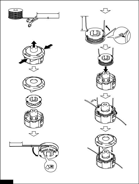
Replacing the nylon cord
 WARNING: Use only the nylon cord with diameter specified in this instruction manual.
Never use heavier line, metal wire, rope or the like. Failure to do so may cause damage to the tool and result in serious personal injury.
 WARNING: Always remove the nylon cutting head from the tool when replacing the nylon cord.
 WARNING: Make sure that the cover of the nylon cutting head is secured to the housing properly as described below. Failure to properly secure the cover may cause the nylon cutting head to fly apart resulting in serious personal injury.
Replace the nylon cord if it is not fed any more. The method of replacing the nylon cord varies depending on the type of the nylon cutting head.
95-M10L
► Fig.38
B&F ECO 4L
► Fig.39
For Ultra Auto 4
► Fig.40
UN-74L
► Fig.41
Manual feed type
When the nylon cord gets short, pull it out from the eyelet and feed it from the another eyelet.
► Fig.42
Replacing the plastic blade
Replace the blade if it is worn out or broken. ► Fig.43
When installing the plastic blade, align the direction of the arrow on the blade with that of the protector.
► Fig.44: 1. Arrow on the protector 2. Arrow on the blade
24 ENGLISH

TROUBLESHOOTING
Before asking for repairs, conduct your own inspection first. If you find a problem that is not explained in the manual, do not attempt to dismantle the tool. Instead, ask Makita Authorized Service Centers, always using Makita replacement parts for repairs.
State of abnormality |
Probable cause (malfunction) |
Remedy |
Motor does not run. |
Battery cartridge is not installed. |
Install the battery cartridge. |
|
Battery problem (under voltage) |
Recharge the battery. If recharging is not effective, |
|
|
replace battery. |
|
The drive system does not work |
Ask your local authorized service center for repair. |
|
correctly. |
|
Motor stops running after a little use. |
Battery's charge level is low. |
Recharge the battery. If recharging is not effective, |
|
|
replace battery. |
|
Overheating. |
Stop using of tool to allow it to cool down. |
It does not reach maximum RPM. |
Battery is installed improperly. |
Install the battery cartridge as described in this |
|
|
manual. |
|
Battery power is dropping. |
Recharge the battery. If recharging is not effective, |
|
|
replace battery. |
|
The drive system does not work |
Ask your local authorized service center for repair. |
|
correctly. |
|
Cutting tool does not rotate: |
Foreign object such as a branch is |
Remove the foreign object. |
stop the machine immediately! |
jammed between the guard and the |
|
|
cutting tool. |
|
|
The drive system does not work |
Ask your local authorized service center for repair. |
|
correctly. |
|
Abnormal vibration: |
One end of the nylon cord has been |
Tap the nylon cutting head against the ground while |
stop the machine immediately! |
broken. |
it is rotating to cause the cord to feed. |
|
The drive system does not work |
Ask your local authorized service center for repair. |
|
correctly. |
|
Cutting tool and motor cannot stop: |
Electric or electronic malfunction. |
Remove the battery and ask your local authorized |
Remove the battery immediately! |
|
service center for repair. |
OPTIONAL
ACCESSORIES
 WARNING: Only use the recommended accessories or attachments indicated in this manual. The use of any other accessory or attachment may result in serious personal injury.
 CAUTION: These accessories or attachments are recommended for use with your Makita tool specified in this manual. The use of any other accessories or attachments might present a risk of injury to persons. Only use accessory or attachment for its stated purpose.
If you need any assistance for more details regarding these accessories, ask your local Makita Service
Center.
•Cutter blade
•Nylon cutting head
•Nylon cord (cutting line)
•Plastic blade
•Protector
•Makita genuine battery and charger
NOTE: Some items in the list may be included in the tool package as standard accessories. They may differ from country to country.
25 ENGLISH

FRANÇAIS (Instructions originales)
SPÉCIFICATIONS
Modèle : |
|
DUR368A |
|
DUR368L |
Type de poignée |
|
Poignée guidon |
|
Poignée arceau |
Vitesse à vide |
Lame de coupe/Tête de coupe |
|
3 : 6 500 min-1 |
|
(à chaque niveau de la vitesse |
à fil nylon/Lame en plastique |
|
2 : 5 300 min-1 |
|
de rotation) |
|
|
1 : 3 500 min-1 |
|
Longueur totale |
|
|
1 758 mm |
|
(sans outil de coupe) |
|
|
|
|
Diamètre du cordon en nylon |
|
|
2,0 à 2,4 mm |
|
Outil de coupe applicable et |
Lame à 3 dents |
|
230 mm |
|
diamètre de coupe |
(P/N : 195298-3) |
|
|
|
|
Lame à 4 dents |
|
230 mm |
|
|
(P/N : B-14118) |
|
|
|
|
Lame à 8 dents |
|
230 mm |
|
|
(P/N : B-14130) |
|
|
|
|
Tête de coupe à fil nylon |
|
350 mm |
|
|
(P/N : 198893-8) |
|
|
|
|
Lame en plastique |
|
255 mm |
|
|
(P/N : 198383-1) |
|
|
|
Tension nominale |
|
|
36 VCC |
|
Poids net |
|
4,1 - 4,7 kg |
|
3,9 - 4,5 kg |
•Étant donné l’évolution constante de notre programme de recherche et de développement, les spécifications contenues dans ce manuel sont sujettes à modification sans préavis.
•Les spécifications peuvent varier suivant les pays.
•Le poids peut être différent selon les accessoires, notamment la batterie. Les associations la plus légère et la plus lourde, conformément à la procédure EPTA 01/2014, sont indiquées dans le tableau.
Batterie, adaptateur de batterie et chargeur applicables
Batterie |
BL1815N / BL1820 / BL1820B / BL1830 / BL1830B / BL1840 / |
|
BL1840B / BL1850 / BL1850B / BL1860B |
Adaptateur de Batterie |
BAP182 / BL36120A |
Chargeur |
DC18RC / DC18RD / DC18RE / DC18SD / DC18SE / DC18SF / DC18SH |
•Certains chargeurs, adaptateurs de batterie et batteries répertoriés ci-dessus peuvent ne pas être disponibles selon la région où vous résidez.
 AVERTISSEMENT : N’utilisez que les batteries, les adaptateurs de batterie et les chargeurs répertoriés ci-dessus. L’utilisation d’autres batteries, adaptateurs de batterie et chargeurs peut provoquer des blessures et/ou un incendie.
Bruit
Norme applicable : ISO22868
Modèle DUR368A
Outil de coupe |
Niveau de pression sonore (LpA) |
Niveau de puissance sonore (LWA) |
||||
|
|
dB(A) |
|
dB(A) |
||
|
LpA dB(A) |
|
Incertitude (K) |
LWA dB(A) |
|
Incertitude (K) |
|
|
|
dB(A) |
|
|
dB(A) |
Lame à 4 dents |
74,7 |
|
1,0 |
89,2 |
|
1,6 |
Tête de coupe à fil nylon |
76,4 |
|
1,6 |
89 |
|
1,0 |
Lame en plastique |
75,1 |
|
0,3 |
86 |
|
0,4 |
26 FRANÇAIS

Modèle DUR368L
Outil de coupe |
Niveau de pression sonore (LpA) |
Niveau de puissance sonore (LWA) |
||||
|
|
dB(A) |
|
dB(A) |
||
|
LpA dB(A) |
|
Incertitude (K) |
LWA dB(A) |
|
Incertitude (K) |
|
|
|
dB(A) |
|
|
dB(A) |
Lame à 4 dents |
74,7 |
|
1,0 |
89,2 |
|
1,6 |
Tête de coupe à fil nylon |
76,4 |
|
1,6 |
89 |
|
1,0 |
Lame en plastique |
75,1 |
|
0,3 |
86 |
|
0,4 |
•Même si le niveau de pression sonore indiqué ci-dessus est inférieur ou égal à 80 dB (A), le niveau en fonctionnement peut dépasser 80 dB (A). Portez un serre-tête antibruit.
NOTE : La ou les valeurs d’émission de bruit déclarées ont été mesurées conformément à la méthode de test standard et peuvent être utilisées pour comparer les outils entre eux.
NOTE : La ou les valeurs d’émission de bruit déclarées peuvent aussi être utilisées pour l’évaluation préliminaire de l’exposition.
 AVERTISSEMENT : Portez un serre-tête antibruit.
 AVERTISSEMENT : L’émission de bruit lors de l’usage réel de l’outil électrique peut être différente de la ou des valeurs déclarées, suivant la façon dont l’outil est utilisé, particulièrement selon le type de pièce usinée.
 AVERTISSEMENT : Les mesures de sécurité à prendre pour protéger l’utilisateur doivent être basées sur une estimation de l’exposition dans des conditions réelles d’utilisation (en tenant compte de toutes les composantes du cycle d’utilisation, comme par exemple le moment de sa mise hors tension, lorsqu’il tourne à vide et le moment de son déclenchement).
Vibration
Norme applicable : ISO22867
Modèle DUR368A
Outil de coupe |
Main gauche |
Main droite |
||
|
ah,W (m/s2) |
Incertitude K |
ah,W (m/s2) |
Incertitude K |
|
|
(m/s2) |
|
(m/s2) |
Lame à 4 dents |
2,5 |
1,5 |
2,5 |
1,5 |
|
|
|
||
Tête de coupe à fil nylon |
2,5 |
1,5 |
2,5 |
1,5 |
|
|
|
||
Lame en plastique |
2,5 |
1,5 |
2,5 |
1,5 |
|
|
|
||
Modèle DUR368L |
|
|
|
|
|
|
|
||
Outil de coupe |
Main gauche |
Main droite |
||
|
ah,W (m/s2) |
Incertitude K |
ah,W (m/s2) |
Incertitude K |
|
|
(m/s2) |
|
(m/s2) |
Lame à 4 dents |
2,5 |
1,5 |
2,5 |
1,5 |
|
|
|
||
Tête de coupe à fil nylon |
2,5 |
1,5 |
2,5 |
1,5 |
|
|
|
||
Lame en plastique |
2,5 |
1,5 |
2,5 |
1,5 |
|
|
|
||
NOTE : La ou les valeurs de vibration totales déclarées ont été mesurées conformément à la méthode de test standard et peuvent être utilisées pour comparer les outils entre eux.
NOTE : La ou les valeurs de vibration totales déclarées peuvent aussi être utilisées pour l’évaluation préliminaire de l’exposition.
 AVERTISSEMENT : L’émission de vibrations lors de l’usage réel de l’outil électrique peut être différente de la ou des valeurs déclarées, suivant la façon dont l’outil est utilisé, particulièrement selon le type de pièce usinée.
 AVERTISSEMENT : Les mesures de sécurité à prendre pour protéger l’utilisateur doivent être basées sur une estimation de l’exposition dans des conditions réelles d’utilisation (en tenant compte de toutes les composantes du cycle d’utilisation, comme par exemple le moment de sa mise hors tension, lorsqu’il tourne à vide et le moment de son déclenchement).
27 FRANÇAIS

Symboles
Vous trouverez ci-dessous les symboles utilisés pour l’appareil. Veillez à comprendre leur signification avant toute utilisation.
Veuillez être prudent et rester attentif.
Lire le mode d’emploi.
Maintenez une distance d’au moins 15 m.


 15m(50FT)

Danger ; prendre garde aux projections d’objets.
Attention ; recul
Portez un casque, des lunettes à coques et un serre-tête antibruit.
Portez des gants de protection.
Portez des bottes robustes à semelles antidérapantes. Il est conseillé de porter des chaussures avec embout de sécurité.
Ne pas exposer à l’eau.
Ni-MH Uniquement pour les pays européens Li-ion Ne jetez pas les appareils électriques ou
les batteries avec vos ordures ménagères ! Conformément aux directives européennes relatives aux déchets d’équipements électriques et électroniques et aux piles et accumulateurs ainsi qu’aux déchets de piles et d’accumulateurs et leur mise en œuvre conformément aux lois nationales, les équipements électriques et les piles et batteries en fin de vie doivent faire l’objet d’une collecte sélective et être confiés à une usine de recyclage respectueuse de l’environnement.
Déclaration de conformité CE
Pour les pays européens uniquement
La déclaration de conformité CE est fournie en Annexe A à ce mode d’emploi.
CONSIGNES DE SÉCURITÉ
Consignes de sécurité générales pour outils électriques

 AVERTISSEMENT : Veuillez lire les consignes de sécurité, instructions, illustrations et spécifications qui accompagnent cet outil
électrique. Le non-respect de toutes les instructions indiquées ci-dessous peut entraîner une électrocution, un incendie et/ou de graves blessures.
Conservez toutes les mises en garde et instructions pour référence ultérieure.
Le terme « outil électrique » dans les avertissements fait référence à l’outil électrique alimenté par le secteur (avec cordon d’alimentation) ou à l’outil électrique fonctionnant sur batterie (sans cordon d’alimentation).
Consignes de sécurité importantes pour l’outil
 AVERTISSEMENT : Lisez toutes les consignes de sécurité et toutes les instructions. Il y a risque d’électrocution, d’incendie et/ou de graves blessures si les mises en garde et les instructions ne sont pas respectées.
Conservez toutes les mises en garde et instructions pour référence ultérieure.
Utilisations prévues
1.Cet outil est exclusivement conçu pour couper l’herbe, les mauvaises herbes, les buissons et les broussailles. Il ne doit pas être utilisé à d’autres fins, pour le dressage de bordures ou la taille de haies, par exemple, sous peine de provoquer des blessures.
Généralités
1.Ne laissez jamais des personnes qui ne sont pas familiarisées avec ces instructions, des personnes (y compris les enfants) aux facultés physiques, sensorielles ou mentales diminuées ou sans expérience ni expertise utiliser l’outil. Les enfants doivent être sous la surveillance d’un adulte afin de s’assurer qu’ils ne jouent pas avec l’outil.
2.Avant de démarrer l’outil, lisez ce manuel pour vous familiariser avec le maniement de l’outil.
3.Ne prêtez pas l’outil à une personne ayant une expérience ou une expertise insuffisante en matière de maniement de débroussailleuses et de coupe-herbes.
4.Lorsque vous prêtez l’outil, joignez toujours ce mode d’emploi.
5.Soyez toujours très prudent et attentif lorsque vous manipulez l’outil.
6.N’utilisez jamais l’outil sous l’emprise de l’alcool, de drogues ou de médicaments, ou si vous êtes fatigué ou malade.
7.N’essayez jamais de modifier l’outil.
8.Respectez la réglementation applicable au maniement des débroussailleuses et des coupe-herbes dans votre pays.
Équipement de protection individuelle
► Fig.1
1.Portez un casque de sécurité, des lunettes à coques et des gants de protection pour vous protéger des projections de débris ou des chutes d’objets.
28 FRANÇAIS
2.Portez des protections auditives comme des coquilles anti-bruit afin d’éviter une perte d’audition.
3.Portez des vêtements et des chaussures permettant une utilisation sécuritaire, comme une combinaison de travail et des chaussures robustes anti-dérapantes. Ne portez pas de vêtements amples ni de bijoux. Les pièces
en mouvement peuvent happer les vêtements amples, les bijoux ou les cheveux longs.
4.Si vous touchez la lame de coupe, mettez des gants de protection. Les lames de coupe peuvent gravement couper les mains nues.
Sécurité de l’aire de travail
1.Utilisez uniquement l’outil si vous avez une bonne visibilité et à la lumière du jour. N’utilisez pas l’outil dans l’obscurité ou le brouillard.
2.N’utilisez pas l’outil dans un environnement explosif, par exemple en présence de liquides, gaz ou poussières inflammables. L’outil produit des étincelles qui peuvent enflammer la poussière ou les émanations.
3.Pendant le fonctionnement, ne vous tenez jamais sur une surface instable ou glissante ou sur une pente abrupte. En hiver, faites attention au verglas et à la neige et assu- rez-vous toujours d’avoir une bonne assise.
4.Pendant le fonctionnement, éloignez les badauds ou les animaux d’au moins 15 m de l’outil. Arrêtez l’outil aussitôt que quelqu’un s’approche.
5.N’utilisez jamais l’outil en présence de personnes, particulièrement les enfants et animaux domestiques, à proximité.
6.Avant toute utilisation, examinez l’aire de travail pour vous assurer qu’elle ne présente pas de pierres ou d’autres objets durs. Ils peuvent
être projetés ou provoquer un recul dangereux et entraîner de graves blessures et/ou des dommages matériels.
7. AVERTISSEMENT : L’utilisation de ce produit peut créer de la poussière contenant des produits chimiques susceptibles de provoquer des maladies respiratoires ou autres. Parmi ces produits chimiques, on trouve des composés présents dans les pesticides, insecticides, fertilisants et herbicides. Les risques encourus varient suivant la fréquence d’exposition qu’implique votre travail. Pour réduire votre degré d’exposition à ces produits chimiques : travaillez dans une aire de travail bien aérée et en utilisant des dispositifs de sécurité approuvés, comme des masques anti-poussière spécialement conçus pour filtrer les particules microscopiques.
Sécurité électrique et sécurité des batteries
1.N’exposez pas l’outil à la pluie ou à l’humidité.
Le risque d’électrocution augmente si de l’eau pénètre dans l’outil.
2.N’utilisez pas l’outil s’il est impossible de l’allumer ou de l’éteindre avec l’interrupteur.
Un outil qui ne peut être contrôlé par l’interrupteur représente un danger et doit être réparé.
3.Évitez les démarrages intempestifs. Assurezvous que l’interrupteur est en position d’arrêt avant de mettre en place la batterie, de ramasser ou de transporter l’outil. Porter l’outil en ayant le doigt sur l’interrupteur ou le brancher alors que l’interrupteur est en position de marche est source d’accidents.
4.Ne jetez pas la ou les batteries au feu.
L’élément de la pile pourrait exploser. Consultez les codes locaux pour de possibles instructions de mise au rebut spéciales.
5.N’ouvrez ni ne manipulez la ou les batteries.
L’électrolyte qui s’échappe de la batterie est corrosif et peut irriter la peau ou les yeux. Il peut être toxique en cas d’ingestion.
6.Ne chargez pas la batterie sous la pluie ou dans un endroit mouillé.
Mise en service
1.Avant de monter ou de régler l’outil, retirez la batterie.
2.Avant de manipuler la lame de coupe, mettez des gants de protection.
3.Avant de mettre en place la batterie, inspectez l’outil pour vous assurer qu’il n’est pas endommagé, mal assemblé ou que les vis/ écrous sont desserrés. Affûtez la lame de coupe si elle est émoussée. Si la lame de coupe est tordue ou endommagée, rempla- cez-la. Vérifiez que tous les leviers de commande et les interrupteurs fonctionnent sans problème. Nettoyez et séchez les poignées.
4.N’essayez jamais de mettre l’outil en marche s’il est endommagé ou pas entièrement assemblé. Sinon, vous pourriez gravement vous blesser.
5.Réglez la bandoulière et la poignée selon la corpulence de l’opérateur.
6.Lorsque vous insérez une batterie, éloignez l’accessoire de coupe de votre corps et d’autres objets, y compris le sol. Il pourrait tourner au démarrage et provoquer des blessures ou des dommages matériels et/ou à l’outil.
7.Retirez toute clé de réglage, clé ou couvrelame avant de mettre l’outil sous tension. Un accessoire laissé en place sur une pièce rotative de l’outil peut entraîner des blessures.
8.Un carter de protection doit être installé sur l’outil de coupe. Ne faites jamais tourner l’outil si le carter de protection est endommagé ou n’est pas posé.
9.Assurez-vous qu’il n’y a pas de câbles électriques, de conduites d’eau, de conduites de gaz, etc., présentant un risque s’ils sont endommagés suite à l’utilisation de l’outil.
Fonctionnement
1.En cas d’urgence, éteignez immédiatement l’outil.
2.Si vous détectez une anomalie (par exemple, bruit ou vibration) en cours de fonctionnement, éteignez l’outil et retirez la batterie. N’utilisez pas l’outil tant que la cause n’est pas connue et résolue.
29 FRANÇAIS
3.L’accessoire de coupe continue de tourner pendant un bref instant après la mise hors tension de l’outil. Ne vous précipitez pas pour toucher l’accessoire de coupe.
4.Pendant le fonctionnement, utilisez la bandoulière. Maintenez fermement l’outil contre vous du côté droit.
5.Ne vous penchez pas trop loin. Maintenez constamment une bonne assise et un bon équilibre. Soyez attentif aux obstacles cachés comme les souches d’arbre, racines ou fossés pour éviter de trébucher.
6.Assurez-vous toujours d’être en position stable dans les pentes.
7.Ne courez jamais ; marchez.
8.Ne travaillez jamais depuis une échelle ou un arbre pour éviter de perdre le contrôle.
9.Si l’outil subit un choc violent ou tombe, vérifiez son état avant de poursuivre la tâche. Vérifiez si les commandes et les dispositifs de sécurité fonctionnent correctement. En cas de dommage ou de doute, confiez l’inspection et la réparation à notre centre de service aprèsvente agréé.
10.Reposez-vous régulièrement pour empêcher la perte du contrôle due à la fatigue. Nous recommandons de faire une pause de 10 à 20 minutes toutes les heures.
11.Lorsque vous abandonnez l’outil, même pendant un court instant, retirez toujours la batterie. Un outil sans surveillance avec la batterie en place peut être utilisé par une personne non autorisée et provoquer de graves accidents.
12.Si des herbes ou des branches se coincent entre l’accessoire de coupe et le carter de protection, éteignez toujours l’outil et retirez la batterie avant le nettoyage. Sinon, l’accessoire de coupe peut tourner brusquement et provoquer de graves blessures.
13.Ne touchez jamais les pièces dangereuses en mouvement avant qu’elles ne soient complètement arrêtées et que la batterie soit retirée.
14.Si l’accessoire de coupe heurte des pierres ou d’autres objets durs, éteignez immédiatement l’outil. Puis retirez la batterie et inspectez l’accessoire de coupe.
15.Vérifiez fréquemment pendant l’utilisation que l’accessoire de coupe ne présente pas de fissures ou de dégâts. Avant l’inspection, retirez la batterie et patientez jusqu’à ce que l’accessoire de coupe s’arrête complètement. Remplacez immédiatement l’accessoire de coupe s’il est abîmé, même s’il ne présente que des fissures superficielles.
16.Ne réalisez jamais de coupe plus haut que votre taille.
17.Avant de commencer à couper, patientez jusqu’à ce que l’accessoire de coupe atteigne une vitesse constante après la mise sous tension de l’outil.
18.Lorsque vous utilisez une lame de coupe, faites osciller de manière égale l’outil en demicercle de droite à gauche, comme si vous utilisiez une faux.
19.Tenez l’outil uniquement par ses surfaces de prise isolées, car la lame de coupe pourrait entrer en contact avec le câblage caché. Le contact
des lames de coupe avec un fil sous tension peut transmettre du courant dans les pièces métalliques exposées de l’outil et électrocuter l’utilisateur.
20.Ne démarrez pas l’outil lorsque de l’herbe coupée est emmêlée dans l’outil de coupe.
21.Avant de démarrer l’outil, assurez-vous que l’outil de coupe ne touche pas le sol et d’autres obstacles comme un arbre.
22.Tenez toujours l’outil à deux mains pendant le fonctionnement. Ne tenez jamais l’outil d’une seule main pendant le fonctionnement.
Outils de coupe
1.N’utilisez pas un outil de coupe non recommandé par nos soins.
2.Utilisez un accessoire de coupe adapté à la tâche.
—Les têtes de coupe à fil nylon (têtes de coupe-herbe) et les lames en plastique conviennent à la tonte de la pelouse.
—Les lames de coupe conviennent à la coupe des mauvaises herbes, de l’herbe haute, des buissons, des arbrisseaux, des broussailles, des fourrés et autres.
—N’utilisez jamais d’autres lames, notamment les chaînes pivotantes à plusieurs pièces en métal et les lames pour fléau. Cela pourrait entraîner des blessures graves.
3.N’utilisez que les outils de coupe marqués d’une vitesse supérieure ou égale à la vitesse marquée sur l’outil.
4.Éloignez toujours vos mains, votre visage et vos vêtements de l’outil de coupe en rotation.
Vous risqueriez autrement de vous blesser.
5.Utilisez toujours le carter de protection de l’accessoire de coupe prévu pour l’accessoire de coupe utilisé.
6.Lorsque vous utilisez des lames de coupe, évitez le recul et préparez-vous toujours à un recul accidentel. Reportez-vous à la section Recul.
7.Lorsque vous ne l’utilisez pas, fixez le couvrelame sur la lame. Déposez le couvercle avant utilisation.
Recul (rebond de la lame)
1.Le recul (rebond de la lame) est une réaction soudaine d’une lame de coupe lorsqu’elle se coince ou accroche. En cas de recul, l’outil est projeté de côté ou vers l’utilisateur avec une grande force, ce qui peut entraîner de graves blessures.
2.Le recul se produit particulièrement lorsque vous appliquez le segment de lame entre midi et 2 heures sur des objets durs, des buissons
et des arbres d’un diamètre de plus de 3 cm. ► Fig.2
3.Pour éviter le recul :
1.Appliquez le segment entre 8 et 11 heures.
2.N’appliquez jamais le segment entre midi et 2 heures.
30 FRANÇAIS
 Loading...