


|
EN |
Cordless Angle Grinder |
INSTRUCTION MANUAL |
8 |
|
|
|
|
|
|
|
Batteridriven |
BRUKSANVISNING |
24 |
|
SV |
|||
|
vinkelslipmaskin |
|||
|
|
|
|
|
|
|
Batteridrevet vinkelsliper |
BRUKSANVISNING |
40 |
|
NO |
|||
|
|
|
|
|
|
|
Akkukäyttöinen |
KÄYTTÖOHJE |
56 |
|
FI |
|||
|
kulmahiomakone |
|||
|
|
|
|
|
|
|
Bezvada leņķa slīpmašīna |
LIETOŠANAS INSTRUKCIJA |
72 |
|
LV |
|||
|
|
|
|
|
|
|
Belaidis kampinis šlifuoklis |
NAUDOJIMO INSTRUKCIJA |
88 |
|
LT |
|||
|
|
|
|
|
|
|
Juhtmeta nurklihvija |
KASUTUSJUHEND |
104 |
|
ET |
|||
|
|
|
|
|
|
|
Аккумуляторная угловая |
РУКОВОДСТВО ПО |
120 |
|
RU |
|||
|
шлифмашина |
ЭКСПЛУАТАЦИИ |
||
|
|
|
DGA417,
DGA418
DGA467,
DGA468
DGA517,
DGA518
|
2 |
|
1 |
|
3 |
Fig.1 |
Fig.5 |
1 |
2 |
Fig.2 |
1 |
1 |
Fig.6 |
1 |
|
|
|
|
|
|
|
|
|
|
|
|
|
|
|
|
|
|
|
|
|
|
|
|
|
|
|
|
|
|
|
|
|
|
|
|
|
|
|
|
|
|
|
|
|
|
|
|
Fig.3 |
|
|
|
Fig.7 |
|
||||||
Fig.4 |
Fig.8 |
2

Fig.9 |
Fig.13 |
Fig.10 |
Fig.14 |
Fig.11 |
Fig.15 |
Fig.12 |
Fig.16 |
3
|
2 |
|
1 |
Fig.17 |
Fig.21 |
|
15° |
Fig.18 |
Fig.22 |
Fig.19 |
Fig.23 |
Fig.20 |
Fig.24 |
4

Fig.25 |
Fig.26 |
1 |
Fig.27 |
4 |
1 |
3 |
2 |
Fig.28 |
5 |
3 |
1 |
|
2 |
Fig.29 |
|
|
1 |
Fig.30

|
|
|
1 |
1 |
2 |
|
2 |
|
|
|
|
|
|
1 |
|
|
|
2 |
Fig.34 |
|
|
|
|
|
|
|
1 |
Fig.31 |
|
|
|
Fig.35
Fig.32
1
1
Fig.36
Fig.33
6
1 |
2 |
|
1 |
|
2 |
Fig.37 |
|
1 |
2 |
Fig.38 |
1 |
Fig.39 |
|
|
1 |
|
|
|
2 |
2 |
2 |
12 |
13 |
15 |
|
|
8 |
|
|
|
3 |
3 |
11 |
|
|
|
|
6 |
9 |
|
3 |
3 |
4 |
|
|
|||
|
10 |
|
|
|
|
|
7 |
|
14 |
14 |
|
5 |
|
|
|||
5 |
|
|
5 |
5 |
|
|
|
|
|||
Fig.40 |
|
|
|
|
|
7
ENGLISH (Original instructions)
SPECIFICATIONS
Model: |
DGA417 |
|
DGA418 |
Wheel diameter |
|
100 mm (4″) |
|
Max. wheel thickness |
|
6.4 mm |
|
Spindle thread |
|
M10 |
|
Rated speed (n) |
|
8,500 min-1 |
|
Overall length |
|
382 mm |
|
Rated voltage |
|
D.C. 18 V |
|
Net weight |
|
2.2 - 2.9 kg |
|
Electric brake |
|
|
|
|
|
|
|
Wireless activation function |
- |
|
|
|
|
|
|
Model: |
DGA467 |
|
DGA468 |
Wheel diameter |
|
115 mm (4-1/2″) |
|
Max. wheel thickness |
|
7.2 mm |
|
Spindle thread |
M14 or 5/8″ (country specific) |
||
Rated speed (n) |
|
8,500 min-1 |
|
Overall length |
|
382 mm |
|
Rated voltage |
|
D.C. 18 V |
|
Net weight |
|
2.4 - 3.1 kg |
|
Electric brake |
|
|
|
|
|
|
|
Wireless activation function |
- |
|
|
|
|
|
|
Model: |
DGA517 |
|
DGA518 |
Wheel diameter |
|
125 mm (5″) |
|
Max. wheel thickness |
|
7.2 mm |
|
Spindle thread |
M14 or 5/8″ (country specific) |
||
Rated speed (n) |
|
8,500 min-1 |
|
Overall length |
|
382 mm |
|
Rated voltage |
|
D.C. 18 V |
|
Net weight |
|
2.4 - 3.1 kg |
|
Electric brake |
|
|
|
|
|
|
|
Wireless activation function |
- |
|
|
|
|
|
|
•Due to our continuing program of research and development, the specifications herein are subject to change without notice.
•Specifications may differ from country to country.
•The weight may differ depending on the attachment(s), including the battery cartridge. The lightest and heaviest combination, according to EPTA-Procedure 01/2014, are shown in the table.
Applicable battery cartridge
BL1815N / BL1820 / BL1820B / BL1830 / BL1830B / BL1840 / BL1840B / BL1850 / BL1850B / BL1860B
•Some of the battery cartridges listed above may not be available depending on your region of residence.
 WARNING: Only use the battery cartridges listed above. Use of any other battery cartridges may cause injury and/or fire.
Intended use
The tool is intended for grinding, sanding and cutting of metal and stone materials without the use of water.
8 ENGLISH

Noise
The typical A-weighted noise level determined according to EN60745:
Model |
Sound pressure |
Sound power level |
Uncertainty (K) : |
|
level (LpA) : (dB(A)) |
(LWA) : (dB(A)) |
(dB(A)) |
DGA417 |
80 |
- |
3 |
DGA418 |
80 |
- |
3 |
DGA467 |
80 |
- |
3 |
DGA468 |
80 |
- |
3 |
DGA517 |
79 |
- |
3 |
DGA518 |
79 |
- |
3 |
The noise level under working may exceed 80 dB (A).

 WARNING: Wear ear protection.
Vibration
The vibration total value (tri-axial vector sum) determined according to EN60745:
Work mode: surface grinding with normal side grip
Model |
Vibration emission (ah, AG) : |
Uncertainty (K) : (m/s2) |
|
(m/s2) |
|
DGA417 |
4.5 |
1.5 |
DGA418 |
4.5 |
1.5 |
DGA467 |
5.5 |
1.5 |
DGA468 |
5.5 |
1.5 |
DGA517 |
6.0 |
1.5 |
DGA518 |
6.0 |
1.5 |
Work mode: surface grinding with anti vibration side grip |
|
|
|
|
|
Model |
Vibration emission (ah, AG) : |
Uncertainty (K) : (m/s2) |
|
(m/s2) |
|
DGA417 |
4.5 |
1.5 |
DGA418 |
4.5 |
1.5 |
DGA467 |
5.0 |
1.5 |
DGA468 |
5.0 |
1.5 |
DGA517 |
5.5 |
1.5 |
DGA518 |
5.5 |
1.5 |
Work mode: disc sanding with normal side grip |
|
|
|
|
|
Model |
Vibration emission (ah, DS) : |
Uncertainty (K) : (m/s2) |
|
(m/s2) |
|
DGA417 |
2.5 m/s2 or less |
1.5 |
DGA418 |
2.5 m/s2 or less |
1.5 |
DGA467 |
2.5 m/s2 or less |
1.5 |
DGA468 |
2.5 m/s2 or less |
1.5 |
DGA517 |
2.5 m/s2 or less |
1.5 |
DGA518 |
2.5 m/s2 or less |
1.5 |
9 ENGLISH

Work mode: disc sanding with anti vibration side grip
Model |
Vibration emission (ah, DS) : |
Uncertainty (K) : (m/s2) |
|
|
(m/s2) |
|
|
DGA417 |
2.5 m/s2 or less |
1.5 |
|
DGA418 |
2.5 m/s2 or less |
1.5 |
|
DGA467 |
2.5 m/s2 |
or less |
1.5 |
DGA468 |
2.5 m/s2 |
or less |
1.5 |
DGA517 |
2.5 m/s2 |
or less |
1.5 |
DGA518 |
2.5 m/s2 |
or less |
1.5 |
NOTE: The declared vibration emission value has been measured in accordance with the standard test method and may be used for comparing one tool with another.
NOTE: The declared vibration emission value may also be used in a preliminary assessment of exposure.
 WARNING: The vibration emission during actual use of the power tool can differ from the declared emission value depending on the ways in which the tool is used.
 WARNING: Be sure to identify safety measures to protect the operator that are based on an estimation of exposure in the actual conditions of use (taking account of all parts of the operating cycle such as the times when the tool is switched off and when it is running idle in addition to the trigger time).
 WARNING: The declared vibration emission value is used for main applications of the power tool. However if the power tool is used for other applications, the vibration emission value may be different.
EC Declaration of Conformity
For European countries only
The EC declaration of conformity is included as Annex A to this instruction manual.
SAFETY WARNINGS
General power tool safety warnings
 WARNING: Read all safety warnings, instructions, illustrations and specifications provided with this power tool. Failure to follow all instructions listed below may result in electric shock, fire and/or serious injury.
Save all warnings and instructions for future reference.
The term "power tool" in the warnings refers to your mains-operated (corded) power tool or battery-operated (cordless) power tool.
Cordless grinder safety warnings
Safety Warnings Common for Grinding, Sanding, Wire Brushing, or Abrasive Cutting-Off Operations:
1.This power tool is intended to function as a grinder, sander, wire brush or cut-off tool. Read all safety warnings, instructions, illustrations and specifications provided with this power tool. Failure to follow all instructions listed below may result in electric shock, fire and/or serious injury.
2.Operations such as polishing are not recommended to be performed with this power tool. Operations for which the power tool was not designed may create a hazard and cause personal injury.
3.Do not use accessories which are not specifically designed and recommended by the tool manufacturer. Just because the accessory can be attached to your power tool, it does not assure safe operation.
4.The rated speed of the accessory must be at least equal to the maximum speed marked on the power tool. Accessories running faster than their rated speed can break and fly apart.
5.The outside diameter and the thickness of your accessory must be within the capacity rating of your power tool. Incorrectly sized accessories cannot be adequately guarded or controlled.
6.Threaded mounting of accessories must match the grinder spindle thread. For accessories mounted by flanges, the arbour hole of the accessory must fit the locating diameter of the flange. Accessories that do not match the mounting hardware of the power tool will run out of balance, vibrate excessively and may cause loss of control.
7.Do not use a damaged accessory. Before each use inspect the accessory such as abrasive wheels for chips and cracks, backing pad for cracks, tear or excess wear, wire brush for loose or cracked wires. If power tool or accessory is dropped, inspect for damage or install an undamaged accessory. After inspecting and installing an accessory, position yourself and bystanders away from the plane of the rotating accessory and run the power tool at maximum no-load speed for one minute. Damaged accessories will normally break apart during this test time.
10 ENGLISH
8.Wear personal protective equipment.
Depending on application, use face shield, safety goggles or safety glasses. As appropriate, wear dust mask, hearing protectors, gloves and workshop apron capable of stopping small abrasive or workpiece fragments.
The eye protection must be capable of stopping flying debris generated by various operations. The dust mask or respirator must be capable of filtrating particles generated by your operation. Prolonged exposure to high intensity noise may cause hearing loss.
9.Keep bystanders a safe distance away from work area. Anyone entering the work area must wear personal protective equipment.
Fragments of workpiece or of a broken accessory may fly away and cause injury beyond immediate area of operation.
10.Hold the power tool by insulated gripping surfaces only, when performing an operation where the cutting tool may contact hidden wiring. Contact with a "live" wire will also make exposed metal parts of the power tool "live" and could give the operator an electric shock.
11.Never lay the power tool down until the accessory has come to a complete stop. The spinning accessory may grab the surface and pull the power tool out of your control.
12.Do not run the power tool while carrying it at your side. Accidental contact with the spinning accessory could snag your clothing, pulling the accessory into your body.
13.Regularly clean the power tool’s air vents. The motor’s fan will draw the dust inside the housing and excessive accumulation of powdered metal may cause electrical hazards.
14.Do not operate the power tool near flammable materials. Sparks could ignite these materials.
15.Do not use accessories that require liquid coolants. Using water or other liquid coolants may result in electrocution or shock.
Kickback and Related Warnings
Kickback is a sudden reaction to a pinched or snagged rotating wheel, backing pad, brush or any other accessory. Pinching or snagging causes rapid stalling of the rotating accessory which in turn causes the uncontrolled power tool to be forced in the direction opposite of the accessory’s rotation at the point of the binding.
For example, if an abrasive wheel is snagged or pinched by the workpiece, the edge of the wheel that is entering into the pinch point can dig into the surface of the material causing the wheel to climb out or kick out.
The wheel may either jump toward or away from the operator, depending on direction of the wheel’s movement at the point of pinching. Abrasive wheels may also break under these conditions.
Kickback is the result of power tool misuse and/or incorrect operating procedures or conditions and can be avoided by taking proper precautions as given below.
1.Maintain a firm grip on the power tool and position your body and arm to allow you to resist kickback forces. Always use auxiliary handle, if provided, for maximum control over kickback or torque reaction during start-up.
The operator can control torque reactions or kickback forces, if proper precautions are taken.
2.Never place your hand near the rotating accessory. Accessory may kickback over your hand.
3.Do not position your body in the area where power tool will move if kickback occurs.
Kickback will propel the tool in direction opposite to the wheel’s movement at the point of snagging.
4.Use special care when working corners, sharp edges etc. Avoid bouncing and snagging the accessory. Corners, sharp edges or bouncing have a tendency to snag the rotating accessory and cause loss of control or kickback.
5.Do not attach a saw chain woodcarving blade or toothed saw blade. Such blades create frequent kickback and loss of control.
Safety Warnings Specific for Grinding and Abrasive Cutting-Off Operations:
1.Use only wheel types that are recommended for your power tool and the specific guard designed for the selected wheel. Wheels for which the power tool was not designed cannot be adequately guarded and are unsafe.
2.The grinding surface of centre depressed wheels must be mounted below the plane of the guard lip. An improperly mounted wheel that projects through the plane of the guard lip cannot be adequately protected.
3.The guard must be securely attached to the power tool and positioned for maximum safety, so the least amount of wheel is exposed towards the operator. The guard helps to protect the operator from broken wheel fragments, accidental contact with wheel and sparks that could ignite clothing.
4.Wheels must be used only for recommended applications. For example: do not grind with the side of cut-off wheel. Abrasive cut-off wheels are intended for peripheral grinding, side forces applied to these wheels may cause them to shatter.
5.Always use undamaged wheel flanges that are of correct size and shape for your selected wheel. Proper wheel flanges support the wheel thus reducing the possibility of wheel breakage. Flanges for cut-off wheels may be different from grinding wheel flanges.
6.Do not use worn down wheels from larger power tools. Wheel intended for larger power tool is not suitable for the higher speed of a smaller tool and may burst.
Additional Safety Warnings Specific for Abrasive Cutting-Off Operations:
1.Do not “jam“ the cut-off wheel or apply excessive pressure. Do not attempt to make an excessive depth of cut. Overstressing the wheel increases the loading and susceptibility to twisting or binding of the wheel in the cut and the possibility of kickback or wheel breakage.
2.Do not position your body in line with and behind the rotating wheel. When the wheel, at the point of operation, is moving away from your body, the possible kickback may propel the spinning wheel and the power tool directly at you.
11 ENGLISH

3.When wheel is binding or when interrupting a cut for any reason, switch off the power tool and hold the power tool motionless until the wheel comes to a complete stop. Never attempt to remove the cut-off wheel from the cut while the wheel is in motion otherwise
kickback may occur. Investigate and take corrective action to eliminate the cause of wheel binding.
4.Do not restart the cutting operation in the workpiece. Let the wheel reach full speed and carefully re-enter the cut. The wheel may bind, walk up or kickback if the power tool is restarted in the workpiece.
5.Support panels or any oversized workpiece to minimize the risk of wheel pinching and kickback. Large workpieces tend to sag under their own weight. Supports must be placed under the workpiece near the line of cut and near the edge of the workpiece on both sides of the wheel.
6.Use extra caution when making a “pocket cut” into existing walls or other blind areas. The protruding wheel may cut gas or water pipes, electrical wiring or objects that can cause kickback.
Safety Warnings Specific for Sanding Operations:
1.Do not use excessively oversized sanding disc paper. Follow manufacturers recommendations, when selecting sanding paper. Larger sanding paper extending beyond the sanding pad presents a laceration hazard and may cause snagging, tearing of the disc or kickback.
Safety Warnings Specific for Wire Brushing
Operations:
1.Be aware that wire bristles are thrown by the brush even during ordinary operation. Do not overstress the wires by applying excessive load to the brush. The wire bristles can easily penetrate light clothing and/or skin.
2.If the use of a guard is recommended for wire brushing, do not allow any interference of the wire wheel or brush with the guard. Wire wheel or brush may expand in diameter due to work load and centrifugal forces.
Additional Safety Warnings:
1.When using depressed centre grinding wheels, be sure to use only fiberglass-reinforced wheels.
2.NEVER USE Stone Cup type wheels with this grinder. This grinder is not designed for these types of wheels and the use of such a product may result in serious personal injury.
3.Be careful not to damage the spindle, the flange (especially the installing surface) or the lock nut. Damage to these parts could result in wheel breakage.
4.Make sure the wheel is not contacting the workpiece before the switch is turned on.
5.Before using the tool on an actual workpiece, let it run for a while. Watch for vibration or wobbling that could indicate poor installation or a poorly balanced wheel.
6.Use the specified surface of the wheel to perform the grinding.
7.Do not leave the tool running. Operate the tool only when hand-held.
8.Do not touch the workpiece immediately after operation; it may be extremely hot and could burn your skin.
9.Observe the instructions of the manufacturer for correct mounting and use of wheels.
Handle and store wheels with care.
10.Do not use separate reducing bushings or adaptors to adapt large hole abrasive wheels.
11.Use only flanges specified for this tool.
12.For tools intended to be fitted with threaded hole wheel, ensure that the thread in the wheel is long enough to accept the spindle length.
13.Check that the workpiece is properly supported.
14.Pay attention that the wheel continues to rotate after the tool is switched off.
15.If working place is extremely hot and humid, or badly polluted by conductive dust, use a short-circuit breaker (30 mA) to assure operator safety.
16.Do not use the tool on any materials containing asbestos.
17.When use cut-off wheel, always work with the dust collecting wheel guard required by domestic regulation.
18.Cutting discs must not be subjected to any lateral pressure.
19.Do not use cloth work gloves during operation.
Fibers from cloth gloves may enter the tool, which causes tool breakage.
SAVE THESE INSTRUCTIONS.
 WARNING: DO NOT let comfort or familiarity with product (gained from repeated use) replace strict adherence to safety rules for the subject product. MISUSE or failure to follow the safety rules stated in this instruction manual may cause serious personal injury.
Important safety instructions for battery cartridge
1.Before using battery cartridge, read all instructions and cautionary markings on (1) battery charger, (2) battery, and (3) product using battery.
2.Do not disassemble battery cartridge.
3.If operating time has become excessively shorter, stop operating immediately. It may result in a risk of overheating, possible burns and even an explosion.
4.If electrolyte gets into your eyes, rinse them out with clear water and seek medical attention right away. It may result in loss of your eyesight.
5.Do not short the battery cartridge:
(1)Do not touch the terminals with any conductive material.
(2)Avoid storing battery cartridge in a container with other metal objects such as nails, coins, etc.
(3)Do not expose battery cartridge to water or rain.
12 ENGLISH

A battery short can cause a large current flow, overheating, possible burns and even a breakdown.
6.Do not store the tool and battery cartridge in locations where the temperature may reach or exceed 50 °C (122 °F).
7.Do not incinerate the battery cartridge even if it is severely damaged or is completely worn out. The battery cartridge can explode in a fire.
8.Be careful not to drop or strike battery.
9.Do not use a damaged battery.
10.The contained lithium-ion batteries are subject to the Dangerous Goods Legislation requirements.
For commercial transports e.g. by third parties, forwarding agents, special requirement on packaging and labeling must be observed.
For preparation of the item being shipped, consulting an expert for hazardous material is required. Please also observe possibly more detailed national regulations.
Tape or mask off open contacts and pack up the battery in such a manner that it cannot move around in the packaging.
11.Follow your local regulations relating to disposal of battery.
12.Use the batteries only with the products specified by Makita. Installing the batteries to non-compliant products may result in a fire, excessive heat, explosion, or leak of electrolyte.
SAVE THESE INSTRUCTIONS.
 CAUTION: Only use genuine Makita batteries.
Use of non-genuine Makita batteries, or batteries that have been altered, may result in the battery bursting causing fires, personal injury and damage. It will also void the Makita warranty for the Makita tool and charger.
Tips for maintaining maximum battery life
1.Charge the battery cartridge before completely discharged. Always stop tool operation and charge the battery cartridge when you notice less tool power.
2.Never recharge a fully charged battery cartridge. Overcharging shortens the battery service life.
3.Charge the battery cartridge with room temperature at 10 °C - 40 °C (50 °F - 104 °F). Let a hot battery cartridge cool down before charging it.
4.Charge the battery cartridge if you do not use it for a long period (more than six months).
Important safety instructions for wireless unit
1.Do not disassemble or tamper with the wireless unit.
2.Keep the wireless unit away from young children. If accidentally swallowed, seek medical attention immediately.
3.Use the wireless unit only with Makita tools.
4.Do not expose the wireless unit to rain or wet conditions.
5.Do not use the wireless unit in places where the temperature exceeds 50°C (122°F).
6.Do not operate the wireless unit in places where medical instruments, such as heart pace makers are near by.
7.Do not operate the wireless unit in places where automated devices are near by. If operated, automated devices may develop malfunction or error.
8.The wireless unit can produce electromagnetic fields (EMF) but they are not harmful to the user.
9.The wireless unit is an accurate instrument. Be careful not to drop or strike the wireless unit.
10.Avoid touching the terminal of the wireless unit with bare hands or metallic materials.
11.Always remove the battery on the tool when installing the wireless unit.
12.When opening the lid of the slot, avoid the place where dust and water may come into the slot. Always keep the inlet of the slot clean.
13.Always insert the wireless unit in the correct direction.
14.Do not press the wireless activation button on the wireless unit too hard and/or press the button with an object with a sharp edge.
15.Always close the lid of the slot when operating.
16.Do not remove the wireless unit from the slot while the power is being supplied to the tool. Doing so may cause a malfunction of the wireless unit.
17.Do not remove the sticker on the wireless unit.
18.Do not put any sticker on the wireless unit.
19.Do not leave the wireless unit in a place where static electricity or electrical noise could be generated.
20.Do not leave the wireless unit in a place subject to high heat, such as a car sitting in the sun.
21.Do not leave the wireless unit in a dusty or powdery place or in a place corrosive gas could be generated.
22.Sudden change of the temperature may bedew the wireless unit. Do not use the wireless unit until the dew is completely dried.
23.When cleaning the wireless unit, gently wipe with a dry soft cloth. Do not use benzine, thinner, conductive grease or the like.
24.When storing the wireless unit, keep it in the supplied case or a static-free container.
25.Do not insert any devices other than Makita wireless unit into the slot on the tool.
26.Do not use the tool with the lid of the slot damaged. Water, dust, and dirt come into the slot may cause malfunction.
27.Do not pull and/or twist the lid of the slot more than necessary. Restore the lid if it comes off from the tool.
28.Replace the lid of the slot if it is lost or damaged.
SAVE THESE INSTRUCTIONS.
13 ENGLISH
FUNCTIONAL
DESCRIPTION
 CAUTION: Always be sure that the tool is switched off and the battery cartridge is removed before adjusting or checking function on the tool.
Installing or removing battery cartridge
 CAUTION: Always switch off the tool before installing or removing of the battery cartridge.
 CAUTION: Hold the tool and the battery cartridge firmly when installing or removing battery cartridge.
Failure to hold the tool and the battery cartridge firmly may cause them to slip off your hands and result in damage to the tool and battery cartridge and a personal injury.
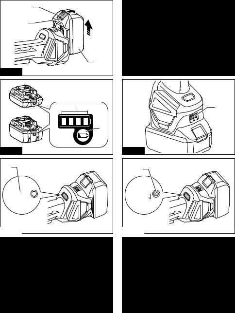
► Fig.1: 1. Red indicator 2. Button 3. Battery cartridge
To remove the battery cartridge, slide it from the tool while sliding the button on the front of the cartridge.
To install the battery cartridge, align the tongue on the battery cartridge with the groove in the housing and slip it into place. Insert it all the way until it locks in place with a little click. If you can see the red indicator on the upper side of the button, it is not locked completely.
 CAUTION: Always install the battery cartridge fully until the red indicator cannot be seen. If not, it may accidentally fall out of the tool, causing injury to you or someone around you.
 CAUTION: Do not install the battery cartridge forcibly. If the cartridge does not slide in easily, it is not being inserted correctly.
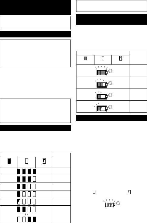
Indicating the remaining battery capacity
Only for battery cartridges with the indicator
► Fig.2: 1. Indicator lamps 2. Check button
Press the check button on the battery cartridge to indicate the remaining battery capacity. The indicator lamps light up for a few seconds.
|
Indicator lamps |
Remaining |
|
|
capacity |
Lighted |
Off |
Blinking |
|
|
75% to 100% |
|
|
50% to 75% |
|
|
25% to 50% |
|
|
0% to 25% |
|
|
Charge the |
|
|
battery. |
|
|
The battery |
|
|
may have |
|
|
malfunctioned. |
|
|
14 |
NOTE: Depending on the conditions of use and the ambient temperature, the indication may differ slightly from the actual capacity.
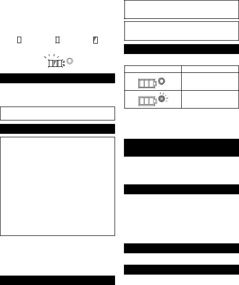
Indicating the remaining battery capacity
Country specific
When you turn the tool on, the battery indicator shows the remaining battery capacity.
► Fig.3: 1. Battery indicator
The remaining battery capacity is shown as the following table.
|
Battery indicator status |
Remaining |
|
|
|
|
battery |
On |
Off |
|
capacity |
Blinking |
|
||
|
|
|
50% to 100% |
|
|
|
20% to 50% |
|
|
|
0% to 20% |
|
|
|
Charge the |
|
|
|
battery |
Tool / battery protection system
The tool is equipped with a tool/battery protection system. This system automatically cuts off power to the motor to extend tool and battery life. The tool will automatically stop during operation if the tool or battery is placed under one of the following conditions:
Overload protection
When the tool is operated in a manner that causes it to draw an abnormally high current, the tool automatically stops without any indication. In this situation, turn the tool off and stop the application that caused the tool to become overloaded. Then turn the tool on to restart.
Overheat protection
When the tool is overheated, the tool stops automatically and the battery indicator shows following state. In this situation, let the tool cool before turning the tool on again.
|
|
|
|
|
|
|
|
|
|
|
|
|
|
|
|
|
|
On |
|
|
|
Blinking |
||||
|
|
|
|
|
|
|
|
|
|
|
|
|
|
|
|
|
|
|
|
|
|
|
|
|
|
|
If the tool does not start, the battery may be overheated. In this situation, let the battery cool before starting the tool again.
ENGLISH
Overdischarge protection
When the battery capacity is not enough, the tool stops automatically. In this case, remove the battery from the tool and charge the battery.
Releasing protection lock
When the protection system works repeatedly, the tool is locked and the battery indicator shows the following state.
In this situation, the tool does not start even if turning the tool off and on. To release the protection lock, remove the battery, set it to the battery charger and wait until the charging finishes.
|
|
|
|
|
|
|
|
|
|
|
|
|
|
|
|
|
|
|
|
|
|
|
|
On |
|
|
Off |
Blinking |
|||||||
|
|
|
|
|
|
|
|
|
|
|
|
|
|
|
|
|
|
|
|
|
|
|
|
|
|
|
|
|
|
|
|
|
|
|
|
Shaft lock
Press the shaft lock to prevent spindle rotation when installing or removing accessories.
► Fig.4: 1. Shaft lock
NOTICE: Never actuate the shaft lock when the spindle is moving. The tool may be damaged.
Switch action
 CAUTION: Before installing the battery cartridge into the tool, always check to see that the switch lever actuates properly and returns to the "OFF" position when released.
 CAUTION: Do not pull the switch lever hard without pulling the lock-off lever. This can cause switch breakage.
 CAUTION: For your safety, this tool is equipped with lock-off lever which prevents the tool from unintended starting. NEVER use the tool if it runs when you simply pull the switch trigger without pulling the lock-off lever. Return the tool to our authorized service center for proper repairs BEFORE further usage.
 CAUTION: NEVER tape down or defeat purpose and function of lock-off lever.
To prevent the switch lever from being accidentally pulled, a lock-off lever is provided.
To start the tool, pull the lock-off lever toward the operator and then pull the switch lever.
To stop the tool, release the switch lever. ► Fig.5: 1. Lock-off lever 2. Switch lever
Speed adjusting dial
The rotation speed of the tool can be changed by turning the speed adjusting dial. The table below shows the number on the dial and the corresponding rotation speed.
► Fig.6: 1. Speed adjusting dial
Number |
Speed |
1 |
3,000 min-1 |
2 |
4,500 min-1 |
3 |
6,000 min-1 |
4 |
7,500 min-1 |
5 |
8,500 min-1 |
NOTICE: If the tool is operated continuously at low speed for a long time, the motor will get overloaded, resulting in tool malfunction.
NOTICE: When changing the speed dial from "5" to "1", turn the dial counterclockwise. Do not turn the dial clockwise forcibly.
Automatic speed change function
► Fig.7: 1. Mode indicator
Mode indicator status |
Operation mode |
|
High speed mode |
|
High torque mode |
This tool has "high speed mode" and "high torque mode". It automatically changes operation mode depending on the work load. When mode indicator lights up during operation, the tool is in high torque mode.
Accidental re-start preventive function
Even if installing the battery cartridge while pulling the switch lever, the tool does not start.
To start the tool, first release the switch lever. Then pull the lock-off lever, and pull the switch lever.
Electronic torque control function
The tool electronically detects situations where the wheel or accessory may be at risk to be bound. In the situation, the tool is automatically shut off to prevent further rotation of the spindle (it does not prevent kickback).
To restart the tool, switch off the tool first, remove the cause of sudden drop in the rotation speed, and then turn the tool on.
Soft start feature
Soft start feature reduces starting reaction.
Electric brake
Electric brake is activated after the tool is switched off.
The brake does not work when the power supply is shut down, such as the battery is removed accidentally, with the switch still on.
15 ENGLISH

ASSEMBLY
 CAUTION: Always be sure that the tool is switched off and the battery cartridge is removed before adjusting or checking function on the tool.
Installing side grip (handle)
 CAUTION: Always be sure that the side grip is installed securely before operation.
Screw the side grip securely on the position of the tool as shown in the figure.
► Fig.8
Installing or removing wheel guard
(For depressed center wheel, flap disc, flex wheel, wire wheel brush / abrasive cut-off wheel, diamond wheel)
 WARNING: When using a depressed center wheel, flap disc, flex wheel or wire wheel brush, the wheel guard must be fitted on the tool so that the closed side of the guard always points toward the operator.
 WARNING: When using an abrasive cut-off
/ diamond wheel, be sure to use only the special wheel guard designed for use with cut-off wheels.
(In some European countries, when using a diamond wheel, the ordinary guard can be used. Follow the regulations in your country.)
For tool with locking screw type wheel guard
Mount the wheel guard with the protrusions on the wheel guard band aligned with the notches on the bearing box. Then rotate the wheel guard to such an angle that it can protect the operator according to work. Be sure to tighten the screw securely.
To remove wheel guard, follow the installation procedure in reverse.
► Fig.9: 1. Wheel guard 2. Bearing box 3. Screw
For tool with clamp lever type wheel guard
Loosen the screw, and then pull the lever in the direction of the arrow. Mount the wheel guard with the protrusions on the wheel guard band aligned with the notches on the bearing box. Then rotate the wheel guard to such an angle that it can protect the operator according to work.
►Fig.10: 1. Wheel guard 2. Bearing box 3. Screw
4.Lever
Pull the lever in direction of the arrow. Then tighten the wheel guard with fastening the screw. Be sure to tighten the screw securely. The setting angle of the wheel guard can be adjusted with the lever.
► Fig.11: 1. Screw 2. Lever
To remove wheel guard, follow the installation procedure in reverse.
Installing or removing depressed center wheel or flap disc
Optional accessory
 WARNING: When using a depressed center wheel or flap disc, the wheel guard must be fitted on the tool so that the closed side of the guard always points toward the operator.
 CAUTION: Make sure that the mounting part of the inner flange fits into the inner diameter of the depressed center wheel / flap disc perfectly.
Mounting the inner flange on the wrong side may result in the dangerous vibration.
Mount the inner flange onto the spindle.
Make sure to fit the dented part of the inner flange onto the straight part at the bottom of the spindle.
Fit the depressed center wheel / flap disc on the inner flange and screw the lock nut onto the spindle.
►Fig.12: 1. Lock nut 2. Depressed center wheel
3.Inner flange 4. Mounting part
To tighten the lock nut, press the shaft lock firmly so that the spindle cannot revolve, then use the lock nut wrench and securely tighten clockwise.
► Fig.13: 1. Lock nut wrench 2. Shaft lock
To remove the wheel, follow the installation procedure in reverse.
Installing or removing flex wheel
Optional accessory
 WARNING: Always use supplied guard when flex wheel is on tool. Wheel can shatter during use and guard helps to reduce chances of personal injury.
►Fig.14: 1. Lock nut 2. Flex wheel 3. Back up pad
4.Inner flange
Follow instructions for depressed center wheel but also use back up pad over wheel. See order of assembly on accessories page in this manual.
Installing or removing abrasive disc
Optional accessory
NOTE: Use sander accessories specified in this manual. These must be purchased separately.
For 100 mm (4″) model
►Fig.15: 1. Sanding lock nut 2. Abrasive disc
3.Rubber pad 4. Inner flange
1.Mount the inner flange onto the spindle.
2.Mount the rubber pad onto the spindle.
3.Fit the disc on the rubber pad and screw the sanding lock nut onto the spindle.
4.Hold the spindle with the shaft lock, and securely tighten the sanding lock nut clockwise with the lock nut wrench.
To remove the disc, follow the installation procedure in reverse.
16 ENGLISH

For 115 mm (4 - 1/2″) / 125 mm (5″) model
►Fig.16: 1. Sanding lock nut 2. Abrasive disc
3.Rubber pad
1.Mount the rubber pad onto the spindle.
2.Fit the disc on the rubber pad and screw the sanding lock nut onto the spindle.
3.Hold the spindle with the shaft lock, and securely tighten the sanding lock nut clockwise with the lock nut wrench.
To remove the disc, follow the installation procedure in reverse.
Connecting a vacuum cleaner
Optional accessory
 WARNING: Never vacuum metal particles created by grinding/cutting/sanding operation.
Metal particles created by such operation are so hot that they ignite dust and the filter inside the vacuum cleaner.
To avoid dusty environment caused by masonry cutting, use a dust collecting wheel guard and a vacuum cleaner.
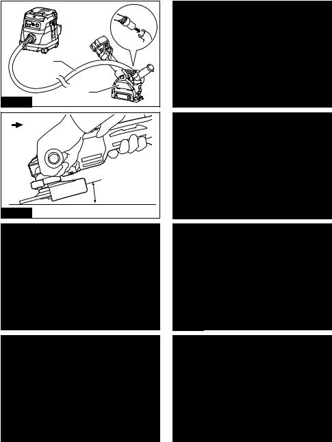
Refer to the instruction manual attached to the dust collecting wheel guard for assembling and using it. ► Fig.17: 1. Dust collecting wheel guard 2. Hose of
the vacuum cleaner
OPERATION
 WARNING: It should never be necessary to force the tool. The weight of the tool applies adequate pressure. Forcing and excessive pressure could cause dangerous wheel breakage.
 WARNING: ALWAYS replace wheel if tool is dropped while grinding.
 WARNING: NEVER bang or hit grinding disc or wheel onto work.
 WARNING: Avoid bouncing and snagging the wheel, especially when working corners, sharp edges etc. This can cause loss of control and kickback.
 WARNING: NEVER use tool with wood cutting blades and other saw blades. Such blades when used on a grinder frequently kick and cause loss of control leading to personal injury.
 CAUTION: Never switch on the tool when it is in contact with the workpiece, it may cause an injury to operator.
 CAUTION: Always wear safety goggles or a face shield during operation.
 CAUTION: After operation, always switch off the tool and wait until the wheel has come to a complete stop before putting the tool down.
 CAUTION: ALWAYS hold the tool firmly with one hand on housing and the other on the side grip (handle).
Grinding and sanding operation
► Fig.18
Turn the tool on and then apply the wheel or disc to the workpiece.
In general, keep the edge of the wheel or disc at an angle of about 15° to the workpiece surface. During the break-in period with a new wheel, do not
work the grinder in forward direction or it may cut into the workpiece. Once the edge of the wheel has been rounded off by use, the wheel may be worked in both forward and backward direction.
Operation with abrasive cut-off / diamond wheel
Optional accessory
 WARNING: When using an abrasive cut-off
/ diamond wheel, be sure to use only the special wheel guard designed for use with cut-off wheels.
(In some European countries, when using a diamond wheel, the ordinary guard can be used. Follow the regulations in your country.)
 WARNING: NEVER use cut-off wheel for side grinding.
 WARNING: Do not "jam" the wheel or apply excessive pressure. Do not attempt to make an excessive depth of cut. Overstressing the wheel increases the loading and susceptibility to twisting or binding of the wheel in the cut and the possibility of kickback, wheel breakage and overheating of the motor may occur.
 WARNING: Do not start the cutting operation in the workpiece. Let the wheel reach full speed and carefully enter into the cut moving the tool forward over the workpiece surface. The wheel may bind, walk up or kickback if the power tool is started in the workpiece.
 WARNING: During cutting operations, never change the angle of the wheel. Placing side pressure on the cut-off wheel (as in grinding) will cause the wheel to crack and break, causing serious personal injury.
 WARNING: A diamond wheel shall be operated perpendicular to the material being cut.
17 ENGLISH

► Fig.19: 1. Lock nut 2. Abrasive cut-off wheel / diamond wheel 3. Inner flange 4. Wheel guard for abrasive cut-off wheel / diamond wheel
As for the installation, follow the instructions for depressed center wheel.
The direction for mounting the lock nut and the inner flange varies by wheel type and thickness.
Refer to the following figures.
For 100 mm (4″) model
When installing the abrasive cut-off wheel:
► Fig.20: 1. Lock nut 2. Abrasive cut-off wheel (Thinner than 4mm (5/32")) 3. Abrasive cutoff wheel (4mm (5/32") or thicker) 4. Inner flange
When installing the diamond wheel:
► Fig.21: 1. Lock nut 2. Diamond wheel (Thinner than 4mm (5/32″)) 3. Diamond wheel (4mm
(5/32″) or thicker) 4. Inner flange
For 115 mm (4 - 1/2″) / 125 mm (5″) model
When installing the abrasive cut-off wheel:
► Fig.22: 1. Lock nut 2. Abrasive cut-off wheel (Thinner than 4mm (5/32")) 3. Abrasive cutoff wheel (4mm (5/32") or thicker) 4. Inner flange
When installing the diamond wheel:
► Fig.23: 1. Lock nut 2. Diamond wheel (Thinner than 4mm (5/32″)) 3. Diamond wheel (4mm
(5/32″) or thicker) 4. Inner flange
Operation with wire cup brush
Optional accessory
 CAUTION: Check operation of brush by running tool with no load, insuring that no one is in front of or in line with brush.
 CAUTION: Do not use brush that is damaged, or which is out of balance. Use of damaged brush could increase potential for injury from contact with broken brush wires.
► Fig.24: 1. Wire cup brush
Remove the battery cartridge from the tool and place it upside down allowing easy access to spindle. Remove any accessories on spindle. Thread wire cup brush onto spindle and tighten with supplied wrench.
NOTICE: Avoid applying too much pressure which causes over bending of wires when using brush. It may lead to premature breakage.
Operation with wire wheel brush
Optional accessory
 CAUTION: Check operation of wire wheel brush by running tool with no load, insuring that no one is in front of or in line with the wire wheel brush.
 CAUTION: Do not use wire wheel brush that is damaged, or which is out of balance. Use of damaged wire wheel brush could increase potential for injury from contact with broken wires.
 CAUTION: ALWAYS use guard with wire wheel brushes, assuring diameter of wheel fits inside guard. Wheel can shatter during use and guard helps to reduce chances of personal injury.
► Fig.25: 1. Wire wheel brush
Remove the battery cartridge from the tool and place it upside down allowing easy access to spindle. Remove any accessories on spindle. Thread wire wheel brush onto spindle and tighten with the wrenches.
NOTICE: Avoid applying too much pressure which causes over bending of wires when using wire wheel brush. It may lead to premature breakage.
WIRELESS ACTIVATION FUNCTION
For DGA418/DGA468/DGA518 only
What you can do with the wireless activation function
The wireless activation function enables clean and comfortable operation. By connecting a supported vacuum cleaner to the tool, you can run the vacuum cleaner automatically along with the switch operation of the tool. ► Fig.26
To use the wireless activation function, prepare following items:
•A wireless unit
•A vacuum cleaner which supports the wireless activation function
The overview of the wireless activation function setting is as follows. Refer to each section for detail procedures.
1.Installing the wireless unit
2.Tool registration for the vacuum cleaner
3.Starting the wireless activation function
18 ENGLISH

Installing the wireless unit
 CAUTION: Place the tool on a flat and stable surface when installing the wireless unit.
NOTICE: Clean the dust and dirt on the tool before installing the wireless unit. Dust or dirt may cause malfunction if it comes into the slot of the wireless unit.
NOTICE: To prevent the malfunction caused by static, touch a static discharging material, such as a metal part of the tool, before picking up the wireless unit.
NOTICE: When installing the wireless unit, always be sure that the wireless unit is inserted in the correct direction and the lid is completely closed.
1.Open the lid on the tool as shown in the figure. ► Fig.27: 1. Lid
2.Insert the wireless unit to the slot and then close the lid.
When inserting the wireless unit, align the projections with the recessed portions on the slot.
►Fig.28: 1. Wireless unit 2. Projection 3. Lid
4.Recessed portion
When removing the wireless unit, open the lid slowly. The hooks on the back of the lid will lift the wireless unit as you pull up the lid.
► Fig.29: 1. Wireless unit 2. Hook 3. Lid
After removing the wireless unit, keep it in the supplied case or a static-free container.
NOTICE: Always use the hooks on the back of the lid when removing the wireless unit. If the hooks do not catch the wireless unit, close the lid completely and open it slowly again.
Tool registration for the vacuum cleaner
NOTE: A Makita vacuum cleaner supporting the wireless activation function is required for the tool registration.
NOTE: Finish installing the wireless unit to the tool before starting the tool registration.
NOTE: During the tool registration, do not pull the switch trigger or turn on the power switch on the vacuum cleaner.
NOTE: Refer to the instruction manual of the vacuum cleaner, too.
If you wish to activate the vacuum cleaner along with the switch operation of the tool, finish the tool registration beforehand.
1.Install the batteries to the vacuum cleaner and the
tool.
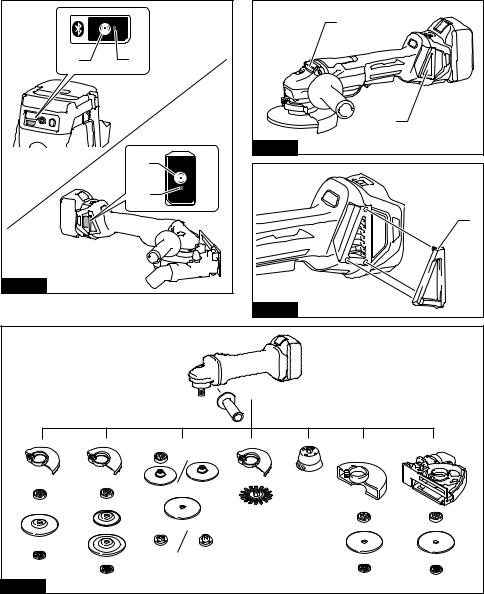
2.Set the stand-by switch on the vacuum cleaner to "AUTO".
► Fig.30: 1. Stand-by switch
3. Press the wireless activation button on the vacuum cleaner for 3 seconds until the wireless activation lamp blinks in green. And then press the wireless activation button on the tool in the same way.
► Fig.31: 1. Wireless activation button 2. Wireless activation lamp
If the vacuum cleaner and the tool are linked successfully, the wireless activation lamps will light up in green for 2 seconds and start blinking in blue.
NOTE: The wireless activation lamps finish blinking in green after 20 seconds elapsed. Press the wireless activation button on the tool while the wireless activation lamp on the cleaner is blinking. If the wireless activation lamp does not blink in green, push the wireless activation button briefly and hold it down again.
NOTE: When performing two or more tool registrations for one vacuum cleaner, finish the tool registration one by one.
Starting the wireless activation function
NOTE: Finish the tool registration for the vacuum cleaner prior to the wireless activation.
NOTE: Refer to the instruction manual of the vacuum cleaner, too.
After registering a tool to the vacuum cleaner, the vacuum cleaner will automatically runs along with the switch operation of the tool.
1.Install the wireless unit to the tool.
2.Connect the hose of the vacuum cleaner with the tool.
► Fig.32
3.Set the stand-by switch on the vacuum cleaner to "AUTO".
► Fig.33: 1. Stand-by switch
4.Push the wireless activation button on the tool briefly. The wireless activation lamp will blink in blue. ► Fig.34: 1. Wireless activation button 2. Wireless
activation lamp
5.Pull the switch trigger of the tool. Check if the vacuum cleaner runs while the switch trigger is being pulled.
To stop the wireless activation of the vacuum cleaner, push the wireless activation button on the tool.
NOTE: The wireless activation lamp on the tool will stop blinking in blue when there is no operation for
2 hours. In this case, set the stand-by switch on the vacuum cleaner to "AUTO" and push the wireless activation button on the tool again.
NOTE: The vacuum cleaner starts/stops with a delay. There is a time lag when the vacuum cleaner detects a switch operation of the tool.
NOTE: The transmission distance of the wireless unit may vary depending on the location and surrounding circumstances.
NOTE: When two or more tools are registered to one vacuum cleaner, the vacuum cleaner may start running even if you don't pull the switch trigger because an other user is using the wireless activation function.
19 ENGLISH
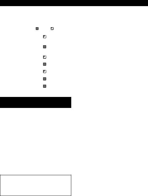
Description of the wireless activation lamp status
► Fig.35: 1. Wireless activation lamp
The wireless activation lamp shows the status of the wireless activation function. Refer to the table below for the meaning of the lamp status.
Status |
|
Wireless activation lamp |
Description |
|||
|
Color |
|
|
|
Duration |
|
|
|
On |
|
Blinking |
|
|
Standby |
Blue |
|
|
|
2 hours |
The wireless activation of the vacuum cleaner is available. The |
|
|
|
|
|
|
lamp will automatically turn off when no operation is performed |
|
|
|
|
|
|
for 2 hours. |
|
|
|
|
|
When |
The wireless activation of the vacuum cleaner is available and the |
|
|
|
|
|
the tool is |
tool is running. |
|
|
|
|
|
running. |
|
Tool |
Green |
|
|
|
20 seconds |
Ready for the tool registration. Waiting for the registration by the |
registration |
|
|
|
|
|
vacuum cleaner. |
|
|
|
|
|
2 seconds |
The tool registration has been finished. The wireless activation |
|
|
|
|
|
|
lamp will start blinking in blue. |
Cancelling |
Red |
|
|
|
20 seconds |
Ready for the cancellation of the tool registration. Waiting for the |
tool |
|
|
|
|
|
cancellation by the vacuum cleaner. |
registration |
|
|
|
|
2 seconds |
The cancellation of the tool registration has been finished. The |
|
|
|
|
|
||
|
|
|
|
|
|
wireless activation lamp will start blinking in blue. |
Others |
Red |
|
|
|
3 seconds |
The power is supplied to the wireless unit and the wireless activa- |
|
|
|
|
|
|
tion function is starting up. |
|
Off |
- |
|
- |
The wireless activation of the vacuum cleaner is stopped. |
|
Cancelling tool registration for the vacuum cleaner
Perform the following procedure when cancelling the tool registration for the vacuum cleaner.
1.Install the batteries to the vacuum cleaner and the
tool.
2.Set the stand-by switch on the vacuum cleaner to "AUTO".
► Fig.36: 1. Stand-by switch
3.Press the wireless activation button on the vacuum cleaner for 6 seconds. The wireless activation lamp blinks in green and then become red. After that, press the wireless activation button on the tool in the same way.
► Fig.37: 1. Wireless activation button 2. Wireless activation lamp
If the cancellation is performed successfully, the wireless activation lamps will light up in red for 2 seconds and start blinking in blue.
NOTE: The wireless activation lamps finish blinking in red after 20 seconds elapsed. Press the wireless activation button on the tool while the wireless activation lamp on the cleaner is blinking. If the wireless activation lamp does not blink in red, push the wireless activation button briefly and hold it down again.
20 ENGLISH
Troubleshooting for wireless activation function
Before asking for repairs, conduct your own inspection first. If you find a problem that is not explained in the manual, do not attempt to dismantle the tool. Instead, ask Makita Authorized Service Centers, always using Makita replacement parts for repairs.
State of abnormality |
Probable cause (malfunction) |
Remedy |
The wireless activation lamp does |
The wireless unit is not installed into |
Install the wireless unit correctly. |
not light/blink. |
the tool. |
|
|
The wireless unit is improperly installed |
|
|
into the tool. |
|
|
The terminal of the wireless unit and/or |
Gently wipe off dust and dirt on the terminal of the |
|
the slot is dirty. |
wireless unit and clean the slot. |
|
The wireless activation button on the |
Push the wireless activation button on the tool |
|
tool has not been pushed. |
briefly. |
|
The stand-by switch on the vacuum |
Set the stand-by switch on the vacuum cleaner to |
|
cleaner is not set to "AUTO". |
"AUTO". |
|
No power supply |
Supply the power to the tool and the vacuum |
|
|
cleaner. |
Cannot finish tool registration / can- |
The wireless unit is not installed into |
Install the wireless unit correctly. |
celling tool registration successfully. |
the tool. |
|
|
The wireless unit is improperly installed |
|
|
into the tool. |
|
|
The terminal of the wireless unit and/or |
Gently wipe off dust and dirt on the terminal of the |
|
the slot is dirty. |
wireless unit and clean the slot. |
|
The stand-by switch on the vacuum |
Set the stand-by switch on the vacuum cleaner to |
|
cleaner is not set to "AUTO". |
"AUTO". |
|
No power supply |
Supply the power to the tool and the vacuum |
|
|
cleaner. |
|
Incorrect operation |
Push the wireless activation button briefly and |
|
|
perform the tool registration/cancellation procedures |
|
|
again. |
|
The tool and vacuum cleaner is away |
Get the tool and vacuum cleaner closer to each |
|
from each other (out of the transmission |
other. The maximum transmission distance is |
|
range). |
approximately 10 m however it may vary according |
|
|
to the circumstances. |
|
Before finishing the tool registration/ |
Push the wireless activation button briefly and |
|
cancellation; |
perform the tool registration/cancellation procedures |
|
- the switch trigger on the tool is pulled |
again. |
|
or; |
|
|
- the power button on the vacuum |
|
|
cleaner is turned on. |
|
|
The tool registration procedures for the |
Perform the tool registration procedures for both the |
|
tool or vacuum cleaner has not finished. |
tool and the vacuum cleaner at the same timing. |
|
Radio disturbance by other appliances |
Keep the tool and vacuum cleaner away from the |
|
which generate high-intensity radio |
appliances such as Wi-Fi devices and microwave |
|
waves. |
ovens. |
21 ENGLISH

State of abnormality |
Probable cause (malfunction) |
Remedy |
The vacuum cleaner does not run |
The wireless unit is not installed into |
Install the wireless unit correctly. |
along with the switch operation of |
the tool. |
|
the tool. |
The wireless unit is improperly installed |
|
|
into the tool. |
|
|
The terminal of the wireless unit and/or |
Gently wipe off dust and dirt on the terminal of the |
|
the slot is dirty. |
wireless unit and clean the slot. |
|
The wireless activation button on the |
Push the wireless activation button briefly and make |
|
tool has not been pushed. |
sure that the wireless activation lamp is blinking |
|
|
in blue. |
|
The stand-by switch on the vacuum |
Set the stand-by switch on the vacuum cleaner to |
|
cleaner is not set to "AUTO". |
"AUTO". |
|
More than 10 tools are registered to the |
Perform the tool registration again. |
|
vacuum cleaner. |
If more than 10 tools are registered to the vacuum |
|
|
cleaner, the tool registered earliest will be cancelled |
|
|
automatically. |
|
The vacuum cleaner erased all tool |
Perform the tool registration again. |
|
registrations. |
|
|
No power supply |
Supply the power to the tool and the vacuum |
|
|
cleaner. |
|
The tool and vacuum cleaner is away |
Get the tool and vacuum cleaner closer each other. |
|
from each other (out of the transmission |
The maximum transmission distance is approxi- |
|
range). |
mately 10 m however it may vary according to the |
|
|
circumstances. |
|
Radio disturbance by other appliances |
Keep the tool and vacuum cleaner away from the |
|
which generate high-intensity radio |
appliances such as Wi-Fi devices and microwave |
|
waves. |
ovens. |
The vacuum cleaner runs while the |
Other users are using the wireless |
Turn off the wireless activation button of the other |
tool's switch trigger is not pulled. |
activation of the vacuum cleaner with |
tools or cancel the tool registration of the other |
|
their tools. |
tools. |
MAINTENANCE
 CAUTION: Always be sure that the tool is switched off and the battery cartridge is removed before attempting to perform inspection or maintenance.
NOTICE: Never use gasoline, benzine, thinner, alcohol or the like. Discoloration, deformation or cracks may result.
Air vent cleaning
The tool and its air vents have to be kept clean. Regularly clean the tool's air vents or whenever the vents start to become obstructed.
► Fig.38: 1. Exhaust vent 2. Inhalation vent
Remove the dust cover from inhalation vent and clean it for smooth air circulation.
► Fig.39: 1. Dust cover
NOTICE: Clean out the dust cover when it is clogged with dust or foreign matters. Continuing operation with a clogged dust cover may damage the tool.
22 ENGLISH

OPTIONAL ACCESSORIES
 CAUTION: These accessories or attachments are recommended for use with your Makita tool specified in this manual. The use of any other accessories or attachments might present a risk of injury to persons. Only use accessory or attachment for its stated purpose.
If you need any assistance for more details regarding these accessories, ask your local Makita Service Center.
•Makita genuine battery and charger
•Wireless unit (For models with wireless activation function) ► Fig.40
- |
100 mm (4″) model |
|
115 mm (4-1/2″) model |
|
125 mm (5″) model |
1 |
|
|
Grip 36 |
|
|
2 |
|
|
Wheel Guard (for grinding wheel) |
|
|
3 |
|
|
Inner flange |
|
|
4 |
|
Depressed center wheel / Flap disc |
|
||
5 |
|
|
Lock nut |
|
|
6 |
|
|
Back up pad |
|
|
7 |
|
|
Flex wheel |
|
|
8 |
Inner flange and rubber pad 76 |
|
Rubber pad 100 |
|
Rubber pad 115 |
9 |
|
|
Abrasive disc |
|
|
10 |
|
|
Sanding lock nut |
|
|
11 |
|
|
Wire wheel brush |
|
|
12 |
|
|
Wire cup brush |
|
|
13 |
|
Wheel Guard (for cut-off wheel) *1 |
|
||
14 |
Abrasive cut-off wheel / Diamond wheel |
|
|||
15 |
|
|
Dust collecting wheel guard |
|
|
- |
|
|
Lock nut wrench |
|
|
NOTE: *1 In some European countries, when using a diamond wheel, the ordinary guard can be used instead of the special guard covering the both side of the wheel. Follow the regulations in your country.
NOTE: Some items in the list may be included in the tool package as standard accessories. They may differ from country to country.
23 ENGLISH

SVENSKA (Originalinstruktioner)
SPECIFIKATIONER
Modell: |
DGA417 |
|
DGA418 |
Kapskivans diameter |
|
100 mm (4″) |
|
Max. skivtjocklek |
|
6,4 mm |
|
Spindelgänga |
|
M10 |
|
Nominellt varvtal (n) |
|
8 500 min-1 |
|
Total längd |
|
382 mm |
|
Märkspänning |
|
18 V likström |
|
Nettovikt |
|
2,2 - 2,9 kg |
|
Elektronisk broms |
|
|
|
|
|
|
|
Funktion för trådlös aktivering |
- |
|
|
|
|
|
|
Modell: |
DGA467 |
|
DGA468 |
Kapskivans diameter |
|
115 mm (4-1/2″) |
|
Max. skivtjocklek |
|
7,2 mm |
|
Spindelgänga |
M14 eller 5/8″ (landsspecifikt) |
||
Nominellt varvtal (n) |
|
8 500 min-1 |
|
Total längd |
|
382 mm |
|
Märkspänning |
|
18 V likström |
|
Nettovikt |
|
2,4 - 3,1 kg |
|
Elektronisk broms |
|
|
|
|
|
|
|
Funktion för trådlös aktivering |
- |
|
|
|
|
|
|
Modell: |
DGA517 |
|
DGA518 |
Kapskivans diameter |
|
125 mm (5″) |
|
Max. skivtjocklek |
|
7,2 mm |
|
Spindelgänga |
M14 eller 5/8″ (landsspecifikt) |
||
Nominellt varvtal (n) |
|
8 500 min-1 |
|
Total längd |
|
382 mm |
|
Märkspänning |
|
18 V likström |
|
Nettovikt |
|
2,4 - 3,1 kg |
|
Elektronisk broms |
|
|
|
|
|
|
|
Funktion för trådlös aktivering |
- |
|
|
|
|
|
|
•På grund av vårt pågående program för forskning och utveckling kan dessa specifikationer ändras utan föregående meddelande.
•Specifikationer kan variera mellan olika länder.
•Vikten kan variera beroende på tillbehören, inklusive batterikassett. Den lättaste och den tyngsta kombinationen enligt EPTA-procedur 01/2014 visas i tabellen.
Tillgänglig batterikassett
BL1815N / BL1820 / BL1820B / BL1830 / BL1830B / BL1840 / BL1840B / BL1850 / BL1850B / BL1860B
•Vissa av batterikassetterna på listan ovan kanske inte finns tillgängliga i din region.
 VARNING: Använd endast batterikassetter från listan ovan. Användning av andra batterikassetter kan orsaka personskada och/eller brand.
Avsedd användning
Maskinen är avsedd för slipning och kapning i trä och stenmaterial utan användning av vatten.
24 SVENSKA

Buller
Den normala bullernivån för A-belastning är bestämd enligt EN60745:
Modell |
Ljudtrycksnivå |
Ljudeffektnivå (LWA) |
Mättolerans (K): |
|
(LpA) : (dB(A)) |
: (dB(A)) |
(dB(A)) |
DGA417 |
80 |
- |
3 |
DGA418 |
80 |
- |
3 |
DGA467 |
80 |
- |
3 |
DGA468 |
80 |
- |
3 |
DGA517 |
79 |
- |
3 |
DGA518 |
79 |
- |
3 |
Bullernivån vid arbete kan överstiga 80 dB (A).

 VARNING: Använd hörselskydd.
Vibration
Det totala vibrationsvärdet (treaxlad vektorsumma) bestämt enligt EN60745:
Arbetsläge: planslipning med normalt sidohandtag
Modell |
Vibrationsemission (ah, AG) |
Mättolerans (K): (m/s2) |
|
: (m/s2) |
|
DGA417 |
4,5 |
1,5 |
DGA418 |
4,5 |
1,5 |
DGA467 |
5,5 |
1,5 |
DGA468 |
5,5 |
1,5 |
DGA517 |
6,0 |
1,5 |
DGA518 |
6,0 |
1,5 |
Arbetsläge: planslipning med anti-vibrationssidohandtag |
|
|
|
|
|
Modell |
Vibrationsemission (ah, AG) |
Mättolerans (K): (m/s2) |
|
: (m/s2) |
|
DGA417 |
4,5 |
1,5 |
DGA418 |
4,5 |
1,5 |
DGA467 |
5,0 |
1,5 |
DGA468 |
5,0 |
1,5 |
DGA517 |
5,5 |
1,5 |
DGA518 |
5,5 |
1,5 |
Arbetsläge: skivslipning med normalt sidohandtag |
|
|
|
|
|
Modell |
Vibrationsemission (ah, DS) : |
Mättolerans (K): (m/s2) |
|
(m/s2) |
|
DGA417 |
2,5 m/s2 eller lägre |
1,5 |
DGA418 |
2,5 m/s2 eller lägre |
1,5 |
DGA467 |
2,5 m/s2 eller lägre |
1,5 |
DGA468 |
2,5 m/s2 eller lägre |
1,5 |
DGA517 |
2,5 m/s2 eller lägre |
1,5 |
DGA518 |
2,5 m/s2 eller lägre |
1,5 |
25 SVENSKA

Arbetsläge: skivslipning med anti-vibrationssidohandtag
Modell |
Vibrationsemission (ah, DS) : |
Mättolerans (K): (m/s2) |
|
|
(m/s2) |
|
|
DGA417 |
2,5 m/s2 eller lägre |
1,5 |
|
DGA418 |
2,5 m/s2 eller lägre |
1,5 |
|
DGA467 |
2,5 m/s2 |
eller lägre |
1,5 |
DGA468 |
2,5 m/s2 |
eller lägre |
1,5 |
DGA517 |
2,5 m/s2 |
eller lägre |
1,5 |
DGA518 |
2,5 m/s2 |
eller lägre |
1,5 |
OBS: Det deklarerade vibrationsemissionsvärdet har uppmätts i enlighet med standardtestmetoden och kan användas för att jämföra en maskin med en annan.
OBS: Det deklarerade vibrationsemissionsvärdet kan också användas i en preliminär bedömning av exponering för vibration.
 VARNING: Viberationsemissionen under faktisk användning av maskinen kan skilja sig från det deklarerade emissionsvärdet, beroende på hur maskinen används.
 VARNING: Var noga med att identifiera säkerhetsåtgärder för att skydda användaren, vilka är grundade på en uppskattning av graden av exponering för vibrationer under de faktiska användningsförhållandena, (ta, förutom avtryckartiden, med alla delar av användarcykeln i beräkningen, som till exempel tiden då maskinen är avstängd och när den går på tomgång).
 VARNING: Det deklarerade vibrationsemissionsvärdet används för maskinens huvudsakliga arbetsuppgifter. Om maskinen används för andra arbetsuppgifter kan däremot vibrationsemissionsvärdet bli annorlunda.
EG-försäkran om överensstämmelse
Gäller endast inom EU
EG-försäkran om överensstämmelse inkluderas som bilaga A till denna bruksanvisning.
SÄKERHETSVARNINGAR
Allmänna säkerhetsvarningar för maskiner
 VARNING: Läs alla säkerhetsvarningar, anvisningar, illustrationer och specifikationer som medföljer det här maskinen. Underlåtenhet att följa instruktionerna kan leda till elstötar, brand och/eller allvarliga personskador.
Spara alla varningar och instruktioner för framtida referens.
Termen ”maskin” som anges i varningarna hänvisar till din eldrivna maskin (sladdansluten) eller batteridrivna maskin (sladdlös).
Säkerhetsvarningar för batteridriven slipmaskin
Säkerhetsvarningar för slipning, stålborstning eller abrasiv skärning:
1.Den här maskinen är utformad för att användas för slipning, stålborstning eller som skärverktyg. Läs alla säkerhetsvarningar, anvisningar, illustrationer och specifikationer som medföljer den här maskinen. Underlåtenhet att följa instruktionerna kan leda till elstötar, brand och/eller allvarliga personskador.
2.Den här maskinen rekommenderas inte för poleringsarbeten. Om maskinen används till andra arbeten än de avsedda, kan det orsaka fara och personskada.
3.Använd inte tillbehör som inte är särskilt tillverkade och rekommenderade av maskinens tillverkare. Även om ett tillbehör kan fästas på maskinen garanterar detta inte säker funktion.
4.Tillbehörets nominella varvtal måste vara minst lika med det maximala varvtalet som anges på verktyget. Tillbehör som används över det nominella varvtalet kan gå sönder och orsaka skador.
5.Tillbehörets ytterdiameter och tjocklek måste vara anpassad till elverktygets kapacitetsklassning. Tillbehör i olämplig storlek kan inte skyddas eller styras tillräckligt väl.
6.Gängorna på tillbehör som monteras måste stämma överens med spindelgängorna på slipmaskinen. För tillbehör som monteras med flänsar måste tillbehörets centrumhål passa i flänsens lokaliseringsdiameter. Tillbehör som inte passar exakt på maskinens monteringsbeslag roterar ojämnt, vibrerar kraftigt och kan leda till att du förlorar kontrollen.
7.Använd inte ett skadat tillbehör. Kontrollera tillbehör som sliprondeller efter hack och sprickor, underlagsplattor efter sprickor, slitage och stålborstar efter lösa eller brutna trådar. Om du tappar maskinen eller ett tillbehör ska du kontrollera att det inte har uppstått några skador, eller så ska tillbehöret bytas ut mot ett oskadat. Efter kontroll och montering av tillbehöret ska du och åskådare hålla er borta från det roterande tillbehöret samtidigt som du kör maskinen på full fart utan last i en minut. Skadade tillbehör går normalt sönder under den här testtiden.
26 SVENSKA
8.Använd personlig skyddsutrustning. Använd visir, korgglasögon eller skyddsglasögon beroende på arbetsuppgift. Använd vid behov dammskydd, hörselskydd, handskar och skyddsförkläde som stoppar små bitar slipmaterial eller fragment från arbetsstycket. Ögonskyddet måste kunna stoppa flygande fragment som uppstår vid olika arbeten.
Dammskyddet eller andningsskyddet måste kunna filtrera partiklar som uppstår vid olika arbeten.
Lång tid i kraftigt buller kan orsaka hörselskador.
9.Håll personer i omgivningen på säkert avstånd från arbetsområdet. Alla som befinner sig
i arbetsområdet måste använda skyddsutrustning. Delar av arbetsstycket eller defekta tillbehör kan flyga iväg och orsaka skador utanför arbetsområdet.
10.Håll maskinen endast i de isolerade handtagen om det finns risk för att skärverktyget kan komma i kontakt med en dold elkabel. Om skärverktyget kommer i kontakt med en strömförande ledning blir maskinens metalldelar strömförande och kan ge användaren en elektrisk stöt.
11.Lägg aldrig elverktyget åt sidan förrän det har stannat helt. Det roterande tillbehöret kan gripa tag i underlaget och du kan förlora kontrollen över maskinen.
12.Kör inte verktyget samtidigt som du bär det.
Oavsiktlig kontakt med det roterande tillbehöret kan leda till att det fastnar i dina kläder och dras in mot kroppen.
13.Rengör regelbundet verktygets ventilationsöppningar. Motorns fläkt suger in damm i höljet och överdriven ansamling av pulveriserad metall kan orsaka elektrisk fara.
14.Använd inte verktyget i närheten av lättantändliga material. Gnistor kan antända dessa material.
15.Använd inte tillbehör som kräver flytande kylvätskor. Att använda vatten eller andra flytande kylvätskor kan orsaka dödsfall eller elektriska stötar.
Bakåtkast och relaterade varningar
Bakåtkast är en plötslig reaktion på fastnypt roterande hjul, underlagsplatta, borste eller annat tillbehör. Nyp och kärvning orsakar stegring av det roterande tillbehöret, och orsakar i sin tur att den okontrollerade maskinen tvingas i motsatt riktning vid kärvningspunkten. Om till exempel en slipskiva fastnar i eller kläms fast av arbetsstycket kan skivans kapande kant gräva sig in i materialytan vid klämpunkten, vilket leder till att skivan klättrar eller kastas tillbaka. Skivan kan antingen hoppa mot eller från användaren, beroende på skivans rörelseriktning vid klämpunkten. Slipskivorna kan även gå sönder under dessa omständigheter.
Bakåtkast beror på ovarsamhet och/eller felaktiga arbetsrutiner, och kan undvikas genom att vidta nedanstående förebyggande åtgärder.
1.Se till att hålla verktyget i ett fast grepp och placera kroppen och din arm på ett sätt som gör att du kan stå emot kraften från bakåtkast. Använd alltid ett extrahandtag, om sådant finns, för maximal kontroll vid bakåtkast eller vridrörelsen vid start. Användaren kan kontrollera vridrörelsen eller krafterna vid bakåtkast om rätt försiktighetsåtgärder vidtas.
2.Placera aldrig din hand nära det roterande tillbehöret. Tillbehöret kan kastas bakåt över din hand.
3.Ställ dig inte där maskinen kommer att förflytta sig i händelse av bakåtkast. Bakåtkast driver verktyget i motsatt riktning till kapskivans rörelse vid kärvningspunkten.
4.Var extra försiktig när du bearbetar hörn, vassa kanter osv. Undvik att studsa och stöta tillbehöret. Hörn, skarpa kanter eller studsning har en tendens att klämma det roterande tillbehöret och orsaka förlorad kontroll eller bakåtkast.
5.Montera inte en sågkedja, snidarblad eller ett tandat sågblad. Sådana blad orsakar ofta bakåtkast och förlorad kontroll.
Säkerhetsvarningar för slipning och abrasiv skärning:
1.Använd endast de skivor som rekommenderas för din maskin och det särskilda sprängskyddet för skivan. Skivor som inte tillverkats för maskinen kan inte skyddas tillräckligt och är inte tillförlitliga.
2.Slipytan på nedsänkta skivor måste monteras under planet från sprängskyddets kant.
En felaktigt monterad skiva som sticker utanför planet från sprängskyddets kant är inte tillräckligt skyddad.
3.Sprängskyddet måste vara ordentligt fäst vid maskinen och placerat för maximal säkerhet, så att minsta möjliga yta av skivan är öppen mot användare. Sprängskyddet skyddar användaren mot trasiga skivdelar, oavsiktlig kontakt med skivan och gnistor som kan antända kläder.
4.Kapskivorna får endast användas till rekommenderade arbetsuppgifter. Till exempel: Slipa inte med en kapskivas utsida. Slipande kapskivor är avsedda för periferislipning. Sidokrafter kan spränga sådana skivor.
5.Använd alltid oskadade skivflänsar i rätt storlek och form till din skiva. Rätt skivflänsar stöder kapskivan och minskar därigenom risken för att skivan går sönder. Flänsar till kapskivor kan skilja sig från flänsar till slipskivor.
6.Använd inte nedslitna skivor för större maskiner. Skivor avsedda för större maskiner är inte lämpliga för mindre maskiners högre varvtal och kan spricka.
Ytterligare särskilda säkerhetsvarningar för abrasiv skärning:
1.”Pressa” inte skivan eller utsätt den för överdrivet tryck. Försök inte att göra ett alltför stort kapdjup. Om kapskivan överbelastas ökar belastningen och risken för att skivan vrids eller fastnar i kapet samt risken för bakåtkast eller att skivan går sönder.
2.Placera inte din kropp längs med eller bakom den roterande skivan. När skivan rör sig ifrån dig, kan ett bakåtkast skicka den roterande skivan och maskinen mot dig.
3.Om kapskivan kärvar eller om ett kap avbryts stänger du av elverktyget och håller det stilla tills skivan har stannat helt. Försök aldrig att ta ut kapskivan ur skäret när skivan är i rörelse, för att undvika bakåtkast. Undersök och vidta korrigeringsåtgärder för att eliminera orsaken till att kapskivan fastnar.
27 SVENSKA

4.Starta inte om kapningen med verktyget kvar i 10. Använd inte separata reducerhylsor eller adap-
arbetsstycket. Låt maskinen nå full hastighet och gå tillbaka i skäret. Kapskivan kan fastna, vandra uppåt eller kastas bakåt om elverktyget startas om i arbetsstycket.
5.Stötta långa eller stora arbetsstycken för att minimera risken för att kapskivan fastnar och kastas bakåt. Stora arbetsstycken tenderar att svikta på grund av sin egen vikt. Stöd måste placeras under arbetsstycket nära såglinjen och nära arbetsstyckets kanter på båda sidorna om kapskivan.
6.Var extra försiktig vid genomstickssågning i en befintlig vägg eller andra dolda utrymmen.
Den utskjutande kapskivan kan kapa gaseller vattenledningar, elledningar eller föremål som kan orsaka bakåtkast.
Säkerhetsvarningar särskilt vid slipning:
1.Använd inte för stora slipskivor. Följ tillverkarens rekommendationer när du väljer slipskiva. Större slippapper som sticker ut utanför underlaget ger risk för rivning och kan orsaka kärvning, rivning av skivan eller bakåtkast.
Säkerhetsvarningar särskilt vid stålborstning:
1.Var uppmärksam på att trådbitar kastas ut från borsten även vid normal användning. Överbelasta inte trådarna genom att anlägga onödigt stor kraft mot borsten. Trådarna kan enkelt gå igenom tunnare klädsel och/eller huden.
2.Om användning av skydd rekommenderas vid stålborstningfår inte borstskivan eller borsten gå emot skyddet. Borstens diameter kan expandera på grund av belastningen eller centrifugalkraften.
Ytterligare säkerhetsvarningar:
1.Vid användning av nedsänkta center-rondel- ler ska endast glasfiberförstärkta rondeller användas.
2.ANVÄND ALDRIG sten-skålskivor med denna slipmaskin. Denna slipmaskin är inte konstruerad för denna typ av skivor och användningen av dessa kan resultera i allvarlig personskada.
3.Var försiktig så att inte spindeln, flänsen (i synnerhet monteringsytan) eller låsmuttern skadas. Skador på någon av dessa delar kan medföra att rondellen förstörs.
4.Se till att rondellen inte är i kontakt med arbetsstycket när du trycker på avtryckaren.
5.Låt verktyget vara igång en stund innan det används på arbetsstycket. Kontrollera att skivan inte vibrerar eller skakar, vilket kan innebära att den är felaktigt monterad eller dåligt balanserad.
6.Slipa endast med den del av rondellen som är avsedd för slipning.
7.Lämna inte maskinen igång. Använd endast maskinen när du håller den i händerna.
8.Rör inte vid arbetsstycket omedelbart efter arbetet. Det kan vara extremt varmt och orsaka brännskador.
9.Följ tillverkarens anvisningar för korrekt montering och användning av rondeller. Hantera rondellerna varsamt och förvara dem på en säker plats.
trar för att kunna använda sliprondeller med större hål.
11.Använd endast flänsar som är avsedda för den här maskinen.
12.Kontrollera att gänglängden i rondellen är tillräckligt lång för spindellängden om rondellen är avsedd att gängas fast.
13.Kontrollera att arbetsstycket är ordentligt fastsatt.
14.Tänk på att rondellen fortsätter att rotera efter att maskinen stängts av.
15.Om arbetsplatsen är extremt varm och fuktig, eller har hög koncentration av elektriskt ledande damm, ska jordfelsbrytare (30 mA) användas för användarens säkerhet.
16.Använd inte maskinen för material som innehåller asbest.
17.Använd alltid föreskrivet dammuppsamlande sprängskydd när du arbetar med kapskiva.
18.Kapskivor får inte utsättas för sidokrafter.
19.Använd inte arbetshandskar i tyg när du arbetar med maskinen. Fibrer från tyghandskar kan komma in i maskinen och orsaka fel.
SPARA DESSA ANVISNINGAR.
 VARNING: GLÖM INTE att också fortsättningsvis strikt följa säkerhetsanvisningarna för maskinen även efter att du blivit van att använda den. Vid FELAKTIG HANTERING av maskinen eller om inte säkerhetsanvisningarna i denna bruksanvisning följs kan följden bli allvarliga personskador.
Viktiga säkerhetsanvisningar för batterikassetten
1.Innan batterikassetten används ska alla instruktioner och varningsmärken på (1) batteriladdaren, (2) batteriet och (3) produkten läsas.
2.Montera inte isär batterikassetten.
3.Om drifttiden blivit avsevärt kortare ska användningen avbrytas omedelbart. Det kan uppstå överhettning, brännskador och t o m en explosion.
4.Om du får elektrolyt i ögonen ska de sköljas med rent vatten och läkare uppsökas omedelbart. Det finns risk för att synen förloras.
5.Kortslut inte batterikassetten.
(1)Rör inte vid polerna med något strömförande material.
(2)Undvik att förvara batterikassetten tillsammans med andra metallobjekt som t.ex. spikar, mynt o.s.v.
(3)Skydda batteriet mot vatten och regn.
En batterikortslutning kan orsaka ett stort strömflöde, överhettning, brand och maskinhaveri.
6.Förvara inte maskinen och batterikassetten på platser där temperaturen kan nå eller överstiga
50 °C.
28 SVENSKA

7.Bränn inte upp batterikassetten även om den är svårt skadad eller helt utsliten.
Batterikassetten kan explodera i öppen eld.
8.Var försiktig så att du inte råkar tappa batteriet och utsätt det inte för stötar.
9.Använd inte ett skadat batteri.
10.De medföljande litiumjonbatterierna är föremål för kraven i gällande lagstiftning för farligt gods.
För kommersiella transporter (av t.ex. tredje parter som speditionsfirmor) måste de särskilda transportkrav som anges på emballaget och etiketter iakttas.
För att förbereda den produkt som ska avsändas krävs att du konsulterar en expert på riskmaterial. Var också uppmärksam på att det i ditt land kan finnas ytterligare föreskrifter att följa.
Tejpa över eller maskera blottade kontakter och packa batteriet på sådant sätt att det inte kan röra sig fritt i förpackningen.
11.Följ lokala föreskrifter beträffande avfallshantering av batteriet.
12.Använd endast batterierna med de produkter som specificerats av Makita. Att använda batterierna med ej godkända produkter kan leda till brand, överdriven värme, explosion eller utläckande elektrolyt.
SPARA DESSA ANVISNINGAR.
 FÖRSIKTIGT: Använda endast äkta Makitabatterier. Användning av oäkta Makita-batterier eller batterier som har manipulerats kan leda till personoch utrustningsskador eller till att batteriet fattar eld.
Det upphäver också Makitas garanti för verktyget och laddaren.
Tips för att uppnå batteriets maximala livslängd
1.Ladda batterikassetten innan den är helt urladdad. Stanna alltid maskinen och ladda batterikassetten när du märker att maskinen blir svagare.
2.Ladda aldrig en fulladdad batterikassett. Överladdning förkortar batteriets livslängd.
3.Ladda batterikassetten vid en rumstemperatur på 10 °C - 40 °C. Låt en varm batterikassett svalna innan den laddas.
4.Ladda batterikassetten om du inte har använt den på länge (mer än sex månader).
Viktiga säkerhetsanvisningar för den trådlösa enheten
1.Montera inte isär eller manipulera den trådlösa enheten.
2.Förvara den trådlösa enheten utom räckhåll för barn. Om den råkar sväljas, sök omedelbart läkarhjälp.
3.Använd den trådlösa enheten endast ihop med
Makita-verktyg.
4.Utsätt inte den trådlösa enheten för regn eller våta förhållanden.
5.Använd inte den trådlösa enheten på platser där temperaturen överstiger 50 °C.
6.Använd inte den trådlösa enheten på platser där medicinska instrument som pacemakers finns i närheten.
7.Använd inte den trådlösa enheten på platser där automatiska enheter finns i närheten. Om de är igång kan automatiska enheter utveckla funktionsstörningar eller fel.
8.Den trådlösa enheten kan alstra elektromagnetiska fält (EMF) men dessa är inte skadliga för användaren.
9.Den trådlösa enheten är ett noggrant instrument. Var försiktig så att du inte råkar tappa den trådlösa enheten eller utsätta den för stötar.
10.Undvik att vidröra den trådlösa enhetens terminal med bara händer eller metallmaterial.
11.Ta alltid bort batteriet på verktyget när du installerar den trådlösa enheten.
12.När du öppnar skårans lock, undvik då det ställe där damm och vatten kan komma in i skåran. Håll alltid skårans inlopp rent.
13.Sätt alltid in den trådlösa enheten i rätt riktning.
14.Tryck inte för hårt på knappen för trådlös aktivering på den trådlösa enheten, och tryck inte på knappen med ett föremål med vass kant.
15.Stäng alltid skårans lock vid körning.
16.Ta inte bort den trådlösa enheten från skåran medan ström tillförs till verktyget. Att göra det kan orsaka funktionsfel på den trådlösa enheten.
17.Ta inte bort dekalen på den trådlösa enheten.
18.Sätt inte någon dekal på den trådlösa enheten.
19.Lämna inte den trådlösa enheten någonstans där det kan skapas statisk elektricitet eller elektriskt brus.
20.Lämna inte den trådlösa enheten någonstans där den utsätts för hög värme, t.ex. en bil i solen.
21.Lämna inte den trådlösa enheten på ett dammigt eller pulvrigt ställe eller någonstans där korrosiv gas kan bildas.
22.Plötsliga temperaturförändringar kan göra den trådlösa enheten daggbestänkt. Använd inte den trådlösa enheten förrän daggen helt har torkat bort.
23.När den trådlösa enheten rengörs, torka den då med en torr mjuk duk. Använd inte tvättbensin, thinner, konduktivt fett eller liknande.
24.När den trådlösa enheten ska tas i förvar, ha den då i det tillhörande fodralet eller en behållare med skydd mot statisk laddning.
25.Sätt inte in några andra enheter än den trådlösa Makita-enheten i skåran på verktyget.
26.Använd inte verktyget om skårans lock är skadat. Det kan komma in vatten, damm och smuts i skåran som orsakar funktionsfel.
27.Dra eller vrid inte skårans lock mer än nödvändigt. Sätt tillbaka locket om det lossnar från verktyget.
28.Ersätt skårans lock om det går förlorat eller skadas.
SPARA DESSA ANVISNINGAR.
29 SVENSKA
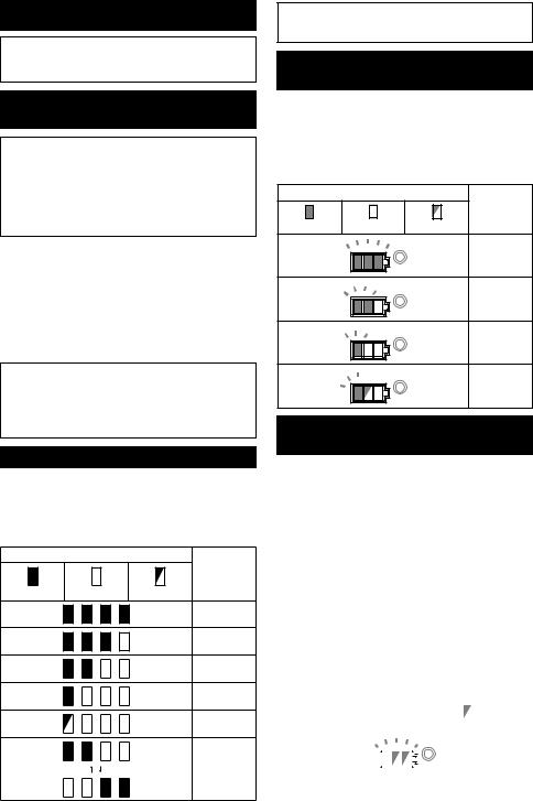
FUNKTIONSBESKRIVNING
 FÖRSIKTIGT: Se alltid till att maskinen är avstängd och batterikassetten borttagen innan du justerar maskinen eller kontrollerar dess funktioner.
Montera eller demontera batterikassetten
 FÖRSIKTIGT: Stäng alltid av maskinen innan du monterar eller tar bort batterikassetten.
 FÖRSIKTIGT: Håll stadigt i maskinen och batterikassetten när du monterar eller tar bort batterikassetten. I annat fall kan det leda till att de glider ur dina händer och orsakar skada på maskinen och batterikassetten samt personskada.
► Fig.1: 1. Röd indikator 2. Knapp 3. Batterikassett
Ta bort batterikassetten genom att skjuta ner knappen på kassettens framsida samtidigt som du drar ut batterikassetten.
Sätt i batterikassetten genom att rikta in tungan på batterikassetten mot spåret i höljet och skjut den på plats. Tryck in batterikassetten ordentligt tills den låser fast med ett klick. Om du kan se den röda indikatorn på knappens ovansida är den inte låst ordentligt.
 FÖRSIKTIGT: Sätt alltid i batterikassetten helt tills den röda indikatorn inte längre syns. I annat fall kan den oväntat falla ur maskinen och skada dig eller någon annan.
 FÖRSIKTIGT: Montera inte batterikassetten med våld. Om kassetten inte lätt glider på plats är den felinsatt.
Indikerar kvarvarande batterikapacitet
Endast för batterikassetter med indikator
► Fig.2: 1. Indikatorlampor 2. Kontrollknapp
Tryck på kontrollknappen på batterikassetten för att se kvarvarande batterikapacitet. Indikatorlamporna lyser i ett par sekunder.
|
Indikatorlampor |
Kvarvarande |
|
|
kapacitet |
Upplyst |
Av |
Blinkar |
|
|
75% till 100% |
|
|
50% till 75% |
|
|
25% till 50% |
|
|
0% till 25% |
|
|
Ladda |
|
|
batteriet. |
|
|
Batteriet kan |
|
|
ha skadats. |
|
|
30 |
OBS: Beroende på användningsförhållanden och den omgivande temperaturen kan indikationen skilja sig lätt från den faktiska batterikapaciteten.
Indikerar kvarvarande batterikapacitet
Landsspecifik
När maskinen startas visar batteriindikatorn kvarvarande batterikapacitet.
► Fig.3: 1. Batteriindikator
Den kvarvarande batterikapaciteten visas som i nedanstående tabell.
|
Batteriindikatorstatus |
Kvarvarande |
|
|
batterikapa- |
På |
Av |
citet |
Blinkar |
||
|
|
50 % till |
|
|
100 % |
|
|
20 % till 50 % |
|
|
0 % till 20 % |
|
|
Ladda |
|
|
batteriet |
Skyddssystem för maskinen/ batteriet
Verktyget är utrustat med ett skyddssystem för verktyget/batteriet. Detta system bryter automatiskt strömmen till motorn för att förlänga verktygets och batteriets livslängd. Verktyget stoppar automatiskt under användningen om verktyget eller batteriet hamnar i en av följande situationer:
Överbelastningsskydd
Om maskinen används på ett sätt som gör att den drar onormalt mycket ström kan den stoppas automatiskt utan någon varning. När detta sker stänger du av maskinen och upphör med arbetet som gjorde att maskinen överbelastades. Starta därefter upp maskinen igen.
Överhettningsskydd
När maskinen är överhettad stoppar den automatiskt och batteriindikatorn visar nedanstående status. Låt då maskinen svalna innan du startar den igen.
|
|
|
|
|
|
|
|
|
|
|
|
|
|
|
|
|
|
|
|
|
|
På |
|
|
Blinkar |
|||||||
|
|
|
|
|
|
|
|
|
|
|
|
|
|
|
|
|
|
|
|
|
|
|
|
|
|
|
|
|
|
|
|
|
Om maskinen inte startar kan det hända att batteriet är överhettat. Låt då batteriet svalna innan du startar maskinen igen.
SVENSKA
 Loading...