


|
EN |
Cordless Impact Wrench |
INSTRUCTION MANUAL |
4 |
|
|
|
|
|
|
|
Akumulatorowy klucz |
INSTRUKCJA OBSŁUGI |
9 |
|
PL |
|||
|
udarowy |
|||
|
|
|
|
|
|
|
Akkumulátoros csavarkulcs |
HASZNÁLATI KÉZIKÖNYV |
15 |
|
HU |
|||
|
|
|
|
|
|
|
Akumulátorový razový |
NÁVOD NA OBSLUHU |
21 |
|
SK |
|||
|
uťahovač |
|||
|
|
|
|
|
|
|
Akumulátorový rázový |
NÁVOD K OBSLUZE |
26 |
|
CS |
|||
|
utahovák |
|||
|
|
|
|
|
|
|
Бездротовий ударний |
ІНСТРУКЦІЯ З |
31 |
|
UK |
|||
|
гайковерт |
ЕКСПЛУАТАЦІЇ |
||
|
|
|
||
|
|
Maşină de înşurubat cu |
MANUAL DE INSTRUCŢIUNI |
37 |
|
RO |
|||
|
impact cu acumulator |
|||
|
|
|
|
|
|
|
Akku-Schlagschrauber |
BETRIEBSANLEITUNG |
43 |
|
DE |
|||
|
|
|
|
|
DTW190

|
1 |
|
|
|
2 |
|
|
|
|
1 |
|
Fig.1 |
3 |
Fig.5 |
|
|
|
||
|
1 |
|
|
|
|
1 |
1 |
Fig.2 |
|
A |
B |
|
|
|
|
|
|
Fig.6 |
|
|
1 |
1 |
|
|
|
|
|
|
2 |
2 |
|
Fig.3 |
|
|
|
|
|
Fig.7 |
|
|
|
1 |
3 |
|
|
2 |
|
|
1 |
|
|
Fig.4 |
|
|
|
|
|
Fig.8 |
|
|
|
2 |
|

3
1 
2 
Fig.9
Fig.10
3

ENGLISH (Original instructions)
SPECIFICATIONS
Model: |
|
DTW190 |
|
Fastening capacities |
Standard bolt |
M8 - M16 |
|
|
High tensile bolt |
M8 - M12 |
|
Square drive |
|
12.7 mm |
|
No load speed |
|
0 - 2,300 min-1 |
|
Impacts per minute |
|
0 - 3,000 min-1 |
|
Overall length |
|
176 mm |
|
Rated voltage |
|
D.C. 18 V |
|
Standard battery cartridge |
|
BL1815, BL1815N, BL1820, |
BL1830, BL1830B, BL1840, |
|
|
BL1820B |
BL1840B, BL1850, BL1850B, |
|
|
|
BL1860B |
Net weight |
|
1.4 kg |
1.7 kg |
•Due to our continuing program of research and development, the specifications herein are subject to change without notice.
•Specifications and battery cartridge may differ from country to country.
•Weight, with battery cartridge, according to EPTA-Procedure 01/2003
Intended use
The tool is intended for fastening bolts and nuts.
Noise
The typicalA-weighted noise level determined according to EN60745:
Sound pressure level (LpA) : 94 dB(A) Sound power level (LWA) : 105 dB (A) Uncertainty (K) : 3 dB(A)

 WARNING: Wear ear protection.
Vibration
The vibration total value (tri-axial vector sum) determined according to EN60745:
Work mode: impact tightening of fasteners of the maximum capacity of the tool
Vibration emission (ah) : 8.5 m/s2
Uncertainty (K) : 1.5 m/s2
NOTE: The declared vibration emission value has been measured in accordance with the standard test method and may be used for comparing one tool with another.
NOTE: The declared vibration emission value may also be used in a preliminary assessment of exposure.
 WARNING: The vibration emission during actual use of the power tool can differ from the declared emission value depending on the ways in which the tool is used.
 WARNING: Be sure to identify safety measures to protect the operator that are based on an estimation of exposure in the actual conditions of use (taking account of all parts of the operating cycle such as the times when the tool is switched off and when it is running idle in addition to the trigger time).
EC Declaration of Conformity
For European countries only
Makita declares that the following Machine(s): Designation of Machine: Cordless Impact Wrench Model No./ Type: DTW190
Conforms to the following European Directives: 2006/42/EC
They are manufactured in accordance with the following standard or standardized documents: EN60745
The technical file in accordance with 2006/42/EC is available from:
Makita, Jan-Baptist Vinkstraat 2, 3070, Belgium 7.16.2015
Yasushi Fukaya
Director
Makita, Jan-Baptist Vinkstraat 2, 3070, Belgium
General power tool safety warnings
 WARNING: Read all safety warnings and all instructions. Failure to follow the warnings and instructions may result in electric shock, fire and/or serious injury.
4 ENGLISH

Save all warnings and instructions for future reference.
The term "power tool" in the warnings refers to your mains-operated (corded) power tool or battery-operated (cordless) power tool.
Cordless impact wrench safety warnings
1.Hold power tool by insulated gripping surfaces, when performing an operation where the fastener may contact hidden wiring.
Fasteners contacting a "live" wire may make exposed metal parts of the power tool "live" and could give the operator an electric shock.
2.Wear ear protectors.
3.Check the impact socket carefully for wear, cracks or damage before installation.
4.Hold the tool firmly.
5.Keep hands away from rotating parts.
6.Always be sure you have a firm footing.
Be sure no one is below when using the tool in high locations.
7.The proper fastening torque may differ depending upon the kind or size of the bolt. Check the torque with a torque wrench.
SAVE THESE INSTRUCTIONS.
 WARNING: DO NOT let comfort or familiarity with product (gained from repeated use) replace strict adherence to safety rules for the subject product.
MISUSE or failure to follow the safety rules stated in this instruction manual may cause serious personal injury.
Important safety instructions for battery cartridge
1.Before using battery cartridge, read all instructions and cautionary markings on (1) battery charger, (2) battery, and (3) product using battery.
2.Do not disassemble battery cartridge.
3.If operating time has become excessively shorter, stop operating immediately. It may result in a risk of overheating, possible burns and even an explosion.
4.If electrolyte gets into your eyes, rinse them out with clear water and seek medical attention right away. It may result in loss of your eyesight.
5.Do not short the battery cartridge:
(1)Do not touch the terminals with any conductive material.
(2)Avoid storing battery cartridge in a container with other metal objects such as nails, coins, etc.
(3)Do not expose battery cartridge to water or rain.
A battery short can cause a large current flow, overheating, possible burns and even a breakdown.
6.Do not store the tool and battery cartridge in locations where the temperature may reach or exceed 50 °C (122 °F).
7.Do not incinerate the battery cartridge even if it is severely damaged or is completely worn out. The battery cartridge can explode in a fire.
8.Be careful not to drop or strike battery.
9.Do not use a damaged battery.
10.The contained lithium-ion batteries are subject to the Dangerous Goods Legislation requirements.
For commercial transports e.g. by third parties, forwarding agents, special requirement on packaging and labeling must be observed.
For preparation of the item being shipped, consulting an expert for hazardous material is required. Please also observe possibly more detailed national regulations.
Tape or mask off open contacts and pack up the battery in such a manner that it cannot move around in the packaging.
11.Follow your local regulations relating to disposal of battery.
SAVE THESE INSTRUCTIONS.
 CAUTION: Only use genuine Makita batteries.
Use of non-genuine Makita batteries, or batteries that have been altered, may result in the battery bursting causing fires, personal injury and damage. It will also void the Makita warranty for the Makita tool and charger.
Tips for maintaining maximum battery life
1.Charge the battery cartridge before completely discharged. Always stop tool operation and charge the battery cartridge when you notice less tool power.
2.Never recharge a fully charged battery cartridge. Overcharging shortens the battery service life.
3.Charge the battery cartridge with room temperature at 10 °C - 40 °C (50 °F - 104 °F). Let a hot battery cartridge cool down before charging it.
4.Charge the battery cartridge if you do not use it for a long period (more than six months).
5 ENGLISH
FUNCTIONAL
DESCRIPTION
 CAUTION: Always be sure that the tool is switched off and the battery cartridge is removed before adjusting or checking function on the tool.
Installing or removing battery cartridge
 CAUTION: Always switch off the tool before installing or removing of the battery cartridge.
 CAUTION: Hold the tool and the battery cartridge firmly when installing or removing battery cartridge. Failure to hold the tool and the battery cartridge firmly may cause them to slip off your hands and result in damage to the tool and battery cartridge and a personal injury.
► Fig.1: 1. Red indicator 2. Button 3. Battery cartridge
To remove the battery cartridge, slide it from the tool while sliding the button on the front of the cartridge.
To install the battery cartridge, align the tongue on the battery cartridge with the groove in the housing and slip it into place. Insert it all the way until it locks in place with a little click. If you can see the red indicator on the upper side of the button, it is not locked completely.
 CAUTION: Always install the battery cartridge fully until the red indicator cannot be seen. If not, it may accidentally fall out of the tool, causing injury to you or someone around you.
 CAUTION: Do not install the battery cartridge forcibly. If the cartridge does not slide in easily, it is not being inserted correctly.
Battery protection system
Lithium-ion battery with star marking
► Fig.2: 1. Star marking
Lithium-ion batteries with a star marking are equipped with a protection system. This system automatically cuts off power to the tool to extend battery life.
The tool will automatically stop during operation if the tool and/or battery are placed under one of the following conditions:
Overloaded:
The tool is operated in a manner that causes it to draw an abnormally high current.
In this situation, turn the tool off and stop the application that caused the tool to become overloaded. Then turn the tool on to restart.
If the tool does not start, the battery is overheated. In this situation, let the battery cool before turning the tool on again.
Low battery voltage:
The remaining battery capacity is too low and the tool will not operate. In this situation, remove and recharge the battery.
Indicating the remaining battery capacity
Only for battery cartridges with "B" at the end of the model number
► Fig.3: 1. Indicator lamps 2. Check button
Press the check button on the battery cartridge to indicate the remaining battery capacity. The indicator lamps light up for few seconds.
|
Indicator lamps |
Remaining |
|
|
capacity |
Lighted |
Off |
Blinking |
|
|
75% to 100% |
|
|
50% to 75% |
|
|
25% to 50% |
|
|
0% to 25% |
|
|
Charge the |
|
|
battery. |
|
|
The battery |
|
|
may have |
|
|
malfunctioned. |
NOTE: Depending on the conditions of use and the ambient temperature, the indication may differ slightly from the actual capacity.
Switch action
► Fig.4: 1. Switch trigger
 CAUTION: Before installing the battery cartridge into the tool, always check to see that the switch trigger actuates properly and returns to the "OFF" position when released.
To start the tool, simply pull the switch trigger. Tool speed is increased by increasing pressure on the switch trigger. Release the switch trigger to stop.
Lighting up the front lamp
► Fig.5: 1. Lamp
 CAUTION: Do not look in the light or see the source of light directly.
Pull the switch trigger to light up the lamp. The lamp keeps on lighting while the switch trigger is being pulled. The lamp goes out just after the switch trigger is released.
NOTE: Use a dry cloth to wipe the dirt off the lens of the lamp. Be careful not to scratch the lens of lamp, or it may lower the illumination.
6 ENGLISH

Reversing switch action
► Fig.6: 1. Reversing switch lever
 CAUTION: Always check the direction of rotation before operation.
 CAUTION: Use the reversing switch only after the tool comes to a complete stop. Changing the direction of rotation before the tool stops may damage the tool.
 CAUTION: When not operating the tool, always set the reversing switch lever to the neutral position.
This tool has a reversing switch to change the direction of rotation. Depress the reversing switch lever from the Aside for clockwise rotation or from the B side for counterclockwise rotation.
When the reversing switch lever is in the neutral position, the switch trigger cannot be pulled.
ASSEMBLY
 CAUTION: Always be sure that the tool is switched off and the battery cartridge is removed before carrying out any work on the tool.
Selecting correct impact socket
Always use the correct size impact socket for bolts and nuts.An incorrect size impact socket will result in inaccurate and inconsistent fastening torque and/or damage to the bolt or nut.
Installing or removing impact socket
 CAUTION: Make sure that the impact socket and the mounting portion are not damaged before installing the impact socket.
 CAUTION: After inserting the socket, make sure that it is firmly secured. If it comes out, do not use it.
For impact socket without O-ring and pin
► Fig.7: 1. Impact socket 2. Square drive
Align the square of the impact socket with the square drive and push the impact socket onto the square drive until it locks into place. Tap it lightly if required.
To remove the impact socket, simply pull it off.
For impact socket with O-ring and pin
► Fig.8: 1. Impact socket 2. O-ring 3. Pin
Move the O-ring out of the groove in the impact socket and remove the pin from the impact socket. Fit the impact socket onto the square drive so that the hole in the impact socket is aligned with the hole in the square drive.
Insert the pin through the hole in the impact socket and square drive. Then return the O-ring to the original position in the impact socket groove to retain the pin.
To remove the impact socket, follow the installation procedures in reverse.
Installing hook
Optional accessory
► Fig.9: 1. Groove 2. Hook 3. Screw
The hook is convenient for temporarily hanging the tool. This can be installed on either side of the tool. To install the hook, insert it into a groove in the tool housing on either side and then secure it with a screw. To remove, loosen the screw and then take it out.
OPERATION
 CAUTION: Always insert the battery cartridge all the way until it locks in place. If you can see the red part on the upper side of the button, it is not locked completely. Insert it fully until the red part cannot be seen. If not, it may accidentally fall out of the tool, causing injury to you or someone around you.
► Fig.10
Hold the tool firmly and place the impact socket over the bolt or nut. Turn the tool on and fasten for the proper fastening time.
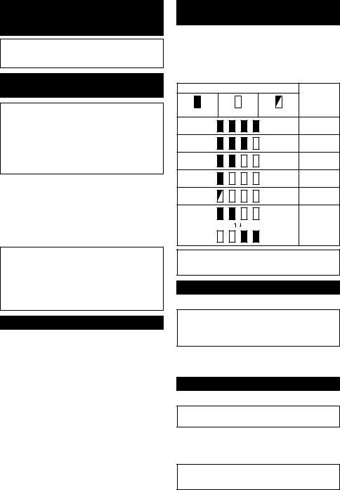
The proper fastening torque may differ depending upon the kind or size of the bolt, the material of the workpiece to be fastened, etc. The relation between fastening torque and fastening time is shown in the figures.
Proper fastening torque for standard bolt
2 |
|
|
|
|
|
|
|
|
|
N•m |
|
|
|
|
|
|
|
|
|
(kgf•cm) |
|
|
|
|
|
|
|
|
|
|
|
|
|
|
|
|
|
|
|
180 |
|
|
|
|
|
|
|
|
|
(1840) |
|
|
|
|
M16 |
||||
160 |
|
|
|
|
|
|
|
|
|
(1630) |
|
|
|
|
|
|
|
|
|
140 |
|
|
|
|
|
|
|
|
|
(1430) |
|
|
|
|
M14 |
||||
120 |
|
|
|
|
|||||
|
|
|
|
|
|
|
|
|
|
(1220) |
|
|
|
|
|
|
|
|
|
100 |
|
|
|
|
|
|
|||
|
|
|
|
M16 |
|||||
(1020) |
|
|
|
|
M12 |
||||
80 |
|
|
|
|
|||||
(820) |
|
|
|
|
|
|
|
|
|
60 |
|
|
|
|
M14 |
|
|||
(610) |
|
|
M10 |
|
|
|
|
|
|
40 |
|
|
|
|
|
|
|
||
|
|
|
|
|
|
|
|
|
|
|
|
|
|
M12 |
|||||
(410) |
|
|
M8 |
||||||
20 |
|
|
|
|
|
|
|
||
|
|
|
|
M10 |
|
||||
|
|
|
|
|
|
||||
(200) |
|
|
|
|
|
|
|
|
|
|
|
|
|
|
|
|
M8 |
|
|
|
|
|
|
|
|
||||
0 0 |
1 |
2 |
3 |
||||||
1
1. Fastening time (second) 2. Fastening torque
7 ENGLISH
Proper fastening torque for high tensile bolt
2
N•m |
|
|
|
|
|
|
|
|
||
(kgf•cm) |
|
|
|
|
|
|
|
M12 |
||
|
|
|
|
|
|
|||||
130 |
|
|
|
|
|
|
|
|||
(1330) |
|
|
|
|
|
|
|
M10 |
||
110 |
|
|
|
|
|
|
|
|||
(1120) |
|
|
|
|
|
|
|
|
|
|
|
|
|
|
|
|
|
|
|
|
|
90 |
|
|
|
|
|
|
|
M12 |
||
|
|
|
|
|
|
|
|
|
|
|
(920) |
|
|
|
|
|
|
|
|
|
|
70 |
|
|
|
|
|
|
|
|
|
|
(710) |
|
|
|
|
|
|
|
|
|
|
|
|
|
|
|
|
|
|
|
|
|
|
|
|
|
|
M8 |
|
|
|
|
|
50 |
|
|
|
|
|
|
M10 |
|||
|
|
|
|
|
|
|
|
|
|
|
(510) |
|
|
|
|
|
|
|
|
|
|
30 |
|
|
|
|
|
|
|
|
|
|
(310) |
|
|
|
|
|
|
|
M8 |
|
|
10 |
|
|
|
|
|
|
|
|
|
|
(100) |
|
|
|
|
|
|
|
|
|
|
0 |
|
|
|
|
|
|
|
|
|
|
|
|
|
|
|
|
|
|
|
|
|
0 |
1 |
2 |
3 |
|||||||
1
1. Fastening time (second) 2. Fastening torque
NOTE: Hold the tool pointed straight at the bolt or nut.
NOTE: Excessive fastening torque may damage the bolt/nut or impact socket. Before starting your job, always perform a test operation to determine the proper fastening time for your bolt or nut.
NOTE: If the tool is operated continuously until the battery cartridge has discharged, allow the tool to rest for 15 minutes before proceeding with a fresh battery cartridge.
The fastening torque is affected by a wide variety of factors including the following.After fastening, always check the torque with a torque wrench.
1.When the battery cartridge is discharged almost completely, voltage will drop and the fastening torque will be reduced.
2.Impact socket
5.The manner of holding the tool or the material of driving position to be fastened will affect the torque.
6.Operating the tool at low speed will cause a reduction in the fastening torque.
MAINTENANCE
 CAUTION: Always be sure that the tool is switched off and the battery cartridge is removed before attempting to perform inspection or maintenance.
NOTICE: Never use gasoline, benzine, thinner, alcohol or the like. Discoloration, deformation or cracks may result.
To maintain product SAFETY and RELIABILITY, repairs, any other maintenance or adjustment should be performed by MakitaAuthorized or Factory Service
Centers, always using Makita replacement parts.
OPTIONAL
ACCESSORIES
 CAUTION: These accessories or attachments are recommended for use with your Makita tool specified in this manual. The use of any other accessories or attachments might present a risk of injury to persons. Only use accessory or attachment for its stated purpose.
If you need any assistance for more details regarding these accessories, ask your local Makita Service Center.
•Plastic carrying case
•Tool hanger
•Shoulder strap
•Hook
•Makita genuine battery and charger
•Failure to use the correct size impact socket NOTE: Some items in the list may be included in the
|
will cause a reduction in the fastening torque. |
tool package as standard accessories. They may |
• |
Aworn impact socket (wear on the hex end |
differ from country to country. |
|
or square end) will cause a reduction in the |
|
|
fastening torque. |
|
3.Bolt
•Even though the torque coefficient and the class of bolt are the same, the proper fastening torque will differ according to the diameter of bolt.
•Even though the diameters of bolts are the same, the proper fastening torque will differ according to the torque coefficient, the class of bolt and the bolt length.
4.The use of the universal joint or the extension bar somewhat reduces the fastening force of the impact wrench. Compensate by fastening for a longer period of time.
8 ENGLISH

POLSKI (Instrukcja oryginalna)
DANE TECHNICZNE
Model: |
|
DTW190 |
|
Zakresy dokręcania |
Śruba zwykła |
M8–M16 |
|
|
Śruba o dużej wytrzymałości |
M8–M12 |
|
Zabierak kwadratowy |
|
12,7 mm |
|
Prędkość bez obciążenia |
|
0–2 300 min-1 |
|
Liczba udarów na minutę |
|
0–3 000 min-1 |
|
Długość całkowita |
|
176 mm |
|
Napięcie znamionowe |
|
Prąd stały 18 V |
|
Standardowy akumulator |
|
BL1815, BL1815N, BL1820, |
BL1830, BL1830B, BL1840, |
|
|
BL1820B |
BL1840B, BL1850, BL1850B, |
|
|
|
BL1860B |
Ciężar netto |
|
1,4 kg |
1,7 kg |
•W związku ze stale prowadzonym przez naszą firmę programem badawczo-rozwojowym niniejsze dane mogą ulec zmianom bez wcześniejszego powiadomienia.
•W innych krajach urządzenie może mieć odmienne parametry techniczne i może być wyposażone w inny akumulator.
•Masa urządzenia wraz z akumulatorem obliczona zgodnie z procedurą EPTA01/2003
Przeznaczenie
Narzędzie jest przeznaczone do dokręcania śrub i nakrętek.
Hałas
Typowy równoważny poziom dźwiękuAokreślony w oparciu o normę EN60745:
Poziom ciśnienia akustycznego (LpA): 94 dB(A) Poziom mocy akustycznej (LWA): 105 dB (A) Niepewność (K): 3 dB(A)

 OSTRZEŻENIE: Nosić ochronniki słuchu.
Drgania
Całkowita wartość poziomu drgań (suma wektorów w 3 osiach) określona zgodnie z normą EN60745:
Tryb pracy: dokręcanie udarowe śrub i wkrętów w maksymalnym zakresie możliwości narzędzia
Emisja drgań (ah): 8,5 m/s2 Niepewność (K): 1,5 m/s2
WSKAZÓWKA: Deklarowana wartość wytwarzanych drgań została zmierzona zgodnie ze standardową metodą testową i można ją wykorzystać do porównywania narzędzi.
WSKAZÓWKA: Deklarowaną wartość wytwarzanych drgań można także wykorzystać we wstępnej ocenie narażenia.
 OSTRZEŻENIE: Drgania wytwarzane podczas rzeczywistego użytkowania elektronarzędzia mogą się różnić od wartości deklarowanej, w zależności od sposobu jego użytkowania.
 OSTRZEŻENIE: W oparciu o szacowane narażenie w rzeczywistych warunkach użytkowania należy określić środki bezpieczeństwa w celu ochrony operatora (uwzględniając wszystkie elementy cyklu działania, tj. czas, kiedy narzędzie jest wyłączone i kiedy pracuje na biegu jałowym, a także czas, kiedy jest włączone).
Deklaracja zgodności WE
Dotyczy tylko krajów europejskich
Firma Makita oświadcza, że poniższe urządzenie(-a): Oznaczenie maszyny:Akumulatorowy klucz udarowy Model nr/typ: DTW190
Jest zgodne z wymogami określonymi w następujących dyrektywach europejskich: 2006/42/EC
Jest/są produkowane zgodnie z następującymi normami lub dokumentami normalizacyjnymi: EN60745 Dokumentacja techniczna zgodna w wymaganiami dyrektywy 2006/42/EC jest dostępna w:
Makita, Jan-Baptist Vinkstraat 2, 3070, Belgia 7.16.2015
Yasushi Fukaya
Dyrektor
Makita, Jan-Baptist Vinkstraat 2, 3070, Belgia
9 POLSKI

Ogólne zasady bezpiecznej eksploatacji elektronarzędzi
 OSTRZEŻENIE: Przeczytać wszystkie ostrzeżenia bezpieczeństwa i wszystkie instrukcje.
Niezastosowanie się do wspomnianych ostrzeżeń i instrukcji może doprowadzić do porażenia prądem elektrycznym, pożaru i/lub poważnych obrażeń ciała.
Wszystkie ostrzeżenia i instrukcje należy zachować do wykorzystania w przyszłości.
Pojęcie „elektronarzędzie", występujące w wymienionych tu ostrzeżeniach, odnosi się do elektronarzędzia zasilanego z sieci elektrycznej (z przewodem zasilającym) lub do elektronarzędzia akumulatorowego (bez przewodu zasilającego).
Ostrzeżenia dotyczące bezpieczeństwa dla akumulatorowego klucza udarowego
1.Trzymać elektronarzędzie za izolowane powierzchnie rękojeści podczas wykonywania prac, przy których wkręcany wkręt lub śruba mogą dotknąć niewidocznej instalacji elektrycznej. Zetknięcie wkrętu lub śruby z przewodem elektrycznym znajdującym się pod napięciem spowoduje, że odsłonięte elementy metalowe narzędzia również znajdą się pod napięciem, grożąc porażeniem operatora prądem elektrycznym.
2.Nosić ochronniki słuchu.
3.Przed przystąpieniem do pracy sprawdzić dokładnie gniazdo udarowe pod kątem zużycia, pęknięć lub uszkodzeń.
4.Narzędzie należy trzymać mocno i pewnie.
5.Trzymać ręce z dala od części obrotowych.
6.Podczas pracy należy zadbać o dobre oparcie dla nóg.
W przypadku pracy na pewnej wysokości upewnić się, że na dole nie przebywają żadne osoby.
7.Odpowiedni moment dokręcania zależy od rodzaju i wielkości śruby. Moment dokręcenia należy sprawdzać za pomocą klucza dynamometrycznego.
ZACHOWAĆ NINIEJSZE
INSTRUKCJE.
 OSTRZEŻENIE: NIE WOLNO pozwolić, aby wygoda lub rutyna (nabyta w wyniku wielokrotnego używania urządzenia) zastąpiły ścisłe przestrzeganie zasad bezpieczeństwa obsługi.
NIEWŁAŚCIWE UŻYTKOWANIE narzędzia lub niestosowanie się do zasad bezpieczeństwa podanych w niniejszej instrukcji obsługi może prowadzić do poważnych obrażeń ciała.
Ważne zasady bezpieczeństwa dotyczące akumulatora
1.Przed użyciem akumulatora zapoznać się ze wszystkimi instrukcjami i znakami ostrzegawczymi na (1) ładowarce, (2) akumulatorze i (3) produkcie, w którym będzie używany akumulator.
2.Akumulatora nie wolno rozbierać.
3.Jeśli czas działania uległ znacznemu skróceniu, należy natychmiast przerwać pracę. Może bowiem dojść do przegrzania, ewentualnych poparzeń, a nawet eksplozji.
4.W przypadku przedostania się elektrolitu do oczu, przemyć je czystą wodą i niezwłocznie uzyskać pomoc lekarską. Może on bowiem spowodować utratę wzroku.
5.Nie doprowadzać do zwarcia akumulatora:
(1)Nie dotykać styków materiałami przewodzącymi prąd.
(2)Unikać przechowywania akumulatora w pojemniku z metalowymi przedmiotami, takimi jak gwoździe, monety itp.
(3)Chronić akumulator przed deszczem lub wodą.
Zwarcie prowadzi do przepływu prądu elektrycznego o dużym natężeniu i przegrzania akumulatora, co w konsekwencji może grozić poparzeniami a nawet awarią urządzenia.
6.Narzędzia i akumulatora nie wolno przechowywać w miejscach, w których temperatura osiąga bądź przekracza 50°C (122°F).
7.Akumulatorów nie wolno spalać, również tych poważnie uszkodzonych lub całkowicie zużytych. Akumulator może eksplodować w ogniu.
8.Chronić akumulator przed upadkiem i uderzeniami.
9.Nie wolno używać uszkodzonego akumulatora.
10.Stanowiące wyposażenie akumulatory lito- wo-jonowe podlegają przepisom dotyczącym produktów niebezpiecznych.
Na potrzeby transportu komercyjnego, np. świadczonego przez firmy trzecie czy spedycyjne, należy przestrzegać specjalnych wymagań w zakresie pakowania i oznaczania etykietami.
Przygotowanie produktu do wysyłki wymaga skonsultowania się ze specjalistą ds. materiałów niebezpiecznych. Należy także przestrzegać przepisów krajowych, które mogą być bardziej szczegółowe. Zakleić taśmą lub zaślepić otwarte styki akumulatora oraz zabezpieczyć go, aby nie mógł się przesuwać w opakowaniu.
11.Postępować zgodnie z przepisami lokalnymi dotyczącymi usuwania akumulatorów.
ZACHOWAĆ NINIEJSZE
INSTRUKCJE.
 PRZESTROGA: Używać wyłącznie oryginalnych akumulatorów firmy Makita. Używanie nieoryginalnych akumulatorów firm innych niż Makita lub akumulatorów, które zostały zmodyfikowane, może spowodować wybuch akumulatora i pożar, obrażenia ciała oraz zniszczenie mienia. Stanowi to również naruszenie warunków gwarancji firmy Makita dotyczących narzędzia i ładowarki.
10 POLSKI
Wskazówki dotyczące zachowania maksymalnej trwałości akumulatora
1.Akumulator należy naładować zanim zostanie do końca rozładowany. Po zauważeniu spadek mocy narzędzia należy przerwać pracę i naładować akumulator.
2.Nie wolno ładować powtórnie w pełni naładowanego akumulatora. Przeładowanie akumulatora skraca jego trwałość.
3.Akumulator należy ładować w temperaturze pokojowej w przedziale 10–40°C (50–104°F). W przypadku gorącego akumulatora przed przystąpieniem do ładowania należy poczekać, aż ostygnie.
4.Akumulatory niklowo-wodorkowe należy naładować po okresie długiego nieużytkowania (dłuższego niż sześć miesięcy).
OPIS DZIAŁANIA
 PRZESTROGA: Przed przystąpieniem do regulacji lub przeglądu narzędzia upewnić się, że jest ono wyłączone, a akumulator został wyjęty.
Wkładanie i wyjmowanie akumulatora
 PRZESTROGA: Przed włożeniem lub wyjęciem akumulatora należy zawsze wyłączyć narzędzie.
 PRZESTROGA: Podczas wkładania lub wyjmowania akumulatora należy mocno trzymać narzędzie i akumulator. W przeciwnym razie mogą się one wyślizgnąć z rąk, powodując uszkodzenie narzędzia lub akumulatora i obrażenia ciała.
►Rys.1: 1. Czerwony wskaźnik 2. Przycisk
3.Akumulator
Aby wyjąć akumulator, przesuń przycisk znajdujący się w przedniej jego części i wysuń akumulator.
Aby włożyć akumulator, wyrównaj występ na akumulatorze z rowkiem w obudowie i wsuń go na swoje miejsce.Akumulator należy wsunąć do oporu, aż się zatrzaśnie na miejscu, co jest sygnalizowane delikatnym kliknięciem. Jeśli w górnej części przycisku jest widoczny czerwony wskaźnik, akumulator nie został całkowicie zatrzaśnięty.
 PRZESTROGA: Akumulator należy włożyć do końca, tak aby czerwony wskaźnik nie był widoczny. W przeciwnym razie może przypadkowo wypaść z narzędzia, powodując obrażenia operatora lub osób postronnych.
 PRZESTROGA: Nie wkładać akumulatora na siłę. Jeśli akumulator nie daje się swobodnie wsunąć, oznacza to, że został włożony nieprawidłowo.
Układ zabezpieczenia akumulatora
Akumulator litowo-jonowy oznaczony gwiazdką
► Rys.2: 1. Znak gwiazdki
Akumulatory litowo-jonowe ze znakiem gwiazdki są wyposażone w układ zabezpieczający. Układ ten automatycznie odcina zasilanie narzędzia w celu wydłużenia żywotności akumulatora.
Narzędzie zostanie automatycznie zatrzymane podczas pracy w następujących sytuacjach związanych z narzędziem/akumulatorem:
Przeciążenie:
Narzędzie pracuje w sposób, który powoduje pobór nadmiernie wysokiego prądu.
W takiej sytuacji należy wyłączyć narzędzie i zaprzestać wykonywania czynności powodującej przeciążenie narzędzia. Następnie należy włączyć narzędzie w celu jego ponownego uruchomienia.
Jeśli narzędzie nie uruchomi się, oznacza to, że akumulator jest przegrzany. W takiej sytuacji, przed ponownym uruchomieniem narzędzia należy odczekać, aż akumulator ostygnie.
Niskie napięcie akumulatora:
Poziom naładowania akumulatora jest zbyt niski, aby narzędzie mogło pracować. W takiej sytuacji należy wyjąć akumulator i go naładować.
Wskazanie stanu naładowania akumulatora
Tylko akumulatory oznaczone literą „B” na końcu model
► Rys.3: 1. Lampki wskaźnika 2. Przycisk kontrolny
Nacisnąć przycisk kontrolny na akumulatorze w celu wyświetlenia stanu naładowania akumulatora. Lampki wskaźnika zaświecą się przez kilka sekund.
|
Lampki wskaźnika |
Pozostała |
|
|
energia |
|
|
akumulatora |
Świeci się |
Wyłączony |
Miga |
|
|
75–100% |
|
|
50–75% |
|
|
25–50% |
|
|
0–25% |
|
|
Naładować |
|
|
akumulator. |
|
|
Akumulator |
|
|
może nie |
|
|
działać |
|
|
poprawnie. |
WSKAZÓWKA: Zależnie od warunków użytkowania i temperatury otoczenia, wskazywany poziom może nieznacznie się różnić od rzeczywistego stanu naładowania akumulatora.
11 POLSKI

Działanie przełącznika
► Rys.4: 1. Spust przełącznika
 PRZESTROGA: Przed włożeniem akumulatora do narzędzia należy zawsze sprawdzić, czy spust przełącznika działa prawidłowo i czy powraca do położenia wyłączenia po jego zwolnieniu.
W celu uruchomienia narzędzia wystarczy pociągnąć spust przełącznika. Prędkość narzędzia zwiększa się wraz ze zwiększaniem nacisku na spust przełącznika. W celu zatrzymania urządzenia należy zwolnić spust przełącznika.
Włączanie lampki czołowej
► Rys.5: 1. Lampka
 PRZESTROGA: Nie patrzeć na światło ani bezpośrednio na źródło światła.
W celu włączenia lampki należy pociągnąć za spust przełącznika. Lampka świeci, dopóki spust przełącznika jest naciskany. Lampka gaśnie od razu po zwolnieniu spustu przełącznika.
WSKAZÓWKA: Aby usunąć zabrudzenia z klosza lampki, należy użyć suchej szmatki. Uważać, aby nie zarysować klosza lampki, gdyż może to zmniejszyć natężenie oświetlenia.
Działanie przełącznika zmiany kierunku obrotów
► Rys.6: 1. Dźwignia przełącznika zmiany kierunku obrotów
 PRZESTROGA: Przed przystąpieniem do pracy należy zawsze sprawdzić ustawiony kierunek obrotów.
 PRZESTROGA: Przełącznika zmiany kierunku obrotów można użyć tylko po całkowitym zatrzymaniu narzędzia. Zmiana kierunku obrotów przed zatrzymaniem się narzędzia grozi jego uszkodzeniem.
 PRZESTROGA: Gdy narzędzie nie jest używane, należy zawsze ustawić dźwignię przełącznika zmiany kierunku obrotów w położeniu neutralnym.
Omawiane narzędzie jest wyposażone w przełącznik umożliwiający zmianę kierunku obrotów. W celu uzyskania obrotów w prawą stronę należy wcisnąć dźwignię przełącznika zmiany kierunku obrotów po stronie A, natomiast aby uzyskać obroty w lewą stronę, należy wcisnąć dźwignię przełącznika po stronie B.
Gdy dźwignia przełącznika zmiany kierunku obrotów znajduje się w położeniu neutralnym, spust przełącznika jest zablokowany.
MONTAŻ
 PRZESTROGA: Przed przystąpieniem do prac konserwacyjnych przy narzędziu upewnić się,
że jest ono wyłączone, a akumulator został wyjęty.
Wybór odpowiedniej nasadki udarowej
Zawsze używać nasadek udarowych o rozmiarze odpowiednim do rozmiaru śrub i nakrętek. Nasadka udarowa o niewłaściwym rozmiarze prowadzi do niedokładnego i nierównomiernego momentu dokręcania i/lub uszkodzenia śruby lub nakrętki.
Zakładanie i zdejmowanie nasadki udarowej
 PRZESTROGA: Przed założeniem nasadki udarowej należy upewnić się, że sama nasadka ani część mocująca nie są uszkodzone.
 PRZESTROGA: Po wsunięciu nasadki należy upewnić się, że jest ona dobrze zamocowana. Jeśli się wysuwa, nie należy jej używać.
Nasadka udarowa bez pierścienia O-ring i kołka
► Rys.7: 1. Nasadka udarowa 2. Zabierak kwadratowy
Wyrównać kwadratowy otwór nasadki udarowej z zabierakiem kwadratowym i wsunąć nasadkę na zabierak, aż nasadka zablokuje się na swoim miejscu. W razie potrzeby lekko puknąć.
Aby zdjąć nasadkę udarową, wystarczy je wyciągnąć.
Nasadka udarowa z pierścieniem O-ring i kołkiem
►Rys.8: 1. Nasadka udarowa 2. Pierścień O-ring
3.Kołek
Wysunąć pierścień O-ring rowka w nasadce udarowej i wyjąć kołek z nasadki. Założyć nasadkę udarową na zabieraku kwadratowym tak, aby otwór w nasadce zrównał się z otworem w zabieraku.
Wsunąć kołek w otwór w nasadce i zabieraku kwadratowym. Następnie zsunąć pierścień O-ring do rowka w nasadce udarowej, aby zabezpieczyć kołek.
Aby zdjąć nasadkę udarową, należy wykonać czynności procedury zakładania w odwrotnej kolejności.
Zamontowanie zaczepu
Osprzęt dodatkowy
► Rys.9: 1. Rowek 2. Zaczep 3. Wkręt
Zaczep służy do wygodnego, tymczasowego zawieszania narzędzia. Można go zamontować z jednej lub z drugiej strony narzędzia.Aby zamontować zaczep, należy wsunąć go w rowek w obudowie narzędzia znajdujący się z obu stron, a następnie przykręcić go dwoma wkrętami.Aby wymontować zaczep, należy odkręcić wkręty i wyjąć zaczep.
12 POLSKI

OBSŁUGA
 PRZESTROGA: Akumulator należy wsunąć do oporu, aż wskoczy na swoje miejsce. Jeśli jest widoczny czerwony element w górnej części przycisku, akumulator nie został całkowicie zatrzaśnięty. Należy go wsunąć do oporu, aż czerwony element przestanie być widoczny. W przeciwnym razie może przypadkowo wypaść z narzędzia, powodując obrażenia operatora lub osób postronnych.
► Rys.10
Trzymać mocno narzędzie i umieścić nasadkę udarową na śrubie lub nakrętce. Włączyć narzędzie i dokręcać przez odpowiedni czas.
Odpowiedni moment dokręcenia zależy od rodzaju i rozmiaru śruby, materiału elementu, do którego wkręca się śrubę itp. Zależność momentu dokręcenia i czasu dokręcania pokazano na rysunkach.
Właściwy moment dokręcenia dla zwykłych śrub
2 |
|
|
|
|
|
|
|
|
|
|
N•m |
|
|
|
|
|
|
|
|
|
|
(kgf•cm) |
|
|
|
|
|
|
|
|
|
|
|
|
|
|
|
|
|
|
|
|
|
180 |
|
|
|
|
|
|
|
|
|
|
(1840) |
|
|
|
|
|
M16 |
||||
160 |
|
|
|
|
|
|
|
|
|
|
(1630) |
|
|
|
|
|
|
|
|
|
|
140 |
|
|
|
|
|
|
|
|
|
|
(1430) |
|
|
|
|
|
M14 |
||||
120 |
|
|
|
|
|
|||||
|
|
|
|
|
|
|
|
|
|
|
(1220) |
|
|
|
|
|
|
|
|
|
|
100 |
|
|
|
|
|
|
|
|||
|
|
|
|
|
M16 |
|||||
(1020) |
|
|
|
|
|
M12 |
||||
80 |
|
|
|
|
|
|||||
(820) |
|
|
|
|
|
|
|
|
|
|
60 |
|
|
|
|
|
M14 |
|
|||
(610) |
|
|
|
M10 |
|
|
|
|
|
|
40 |
|
|
|
|
|
|
|
|
||
|
|
|
|
|
|
|
|
|
|
|
|
|
|
|
|
M12 |
|||||
(410) |
|
|
|
M8 |
||||||
20 |
|
|
|
|
|
|
|
|
||
|
|
|
|
|
M10 |
|
||||
|
|
|
|
|
|
|
||||
(200) |
|
|
|
|
|
|
|
|
|
|
|
|
|
|
|
|
|
|
M8 |
|
|
|
|
|
|
|
|
|
||||
0 0 |
1 |
2 |
3 |
|||||||
1
1. Czas dokręcania (s) 2. Moment dokręcenia
Właściwy moment dokręcenia dla śrub o dużej wytrzymałości
2
N•m |
|
|
|
|
|
|
|
|
||
(kgf•cm) |
|
|
|
|
|
|
|
M12 |
||
|
|
|
|
|
|
|||||
130 |
|
|
|
|
|
|
|
|||
(1330) |
|
|
|
|
|
|
|
M10 |
||
110 |
|
|
|
|
|
|
|
|||
(1120) |
|
|
|
|
|
|
|
|
|
|
|
|
|
|
|
|
|
|
|
|
|
90 |
|
|
|
|
|
|
|
M12 |
||
|
|
|
|
|
|
|
|
|
|
|
(920) |
|
|
|
|
|
|
|
|
|
|
70 |
|
|
|
|
|
|
|
|
|
|
(710) |
|
|
|
|
|
|
|
|
|
|
|
|
|
|
|
|
|
|
|
|
|
|
|
|
|
|
M8 |
|
|
|
|
|
50 |
|
|
|
|
|
|
M10 |
|||
|
|
|
|
|
|
|
|
|
|
|
(510) |
|
|
|
|
|
|
|
|
|
|
30 |
|
|
|
|
|
|
|
|
|
|
(310) |
|
|
|
|
|
|
|
M8 |
|
|
10 |
|
|
|
|
|
|
|
|
|
|
(100) |
|
|
|
|
|
|
|
|
|
|
0 |
|
|
|
|
|
|
|
|
|
|
|
|
|
|
|
|
|
|
|
|
|
0 |
1 |
2 |
3 |
|||||||
1
1. Czas dokręcania (s) 2. Moment dokręcenia
WSKAZÓWKA: Narzędzie powinno być skierowane na wprost śruby lub nakrętki.
WSKAZÓWKA: Nadmierny moment dokręcania może uszkodzić śrubę/nakrętkę lub nasadkę udarową. Przed przystąpieniem do pracy zawsze wykonać próbę, aby ustalić właściwy czas dokręcania dla danej śruby lub nakrętki.
WSKAZÓWKA: Jeśli narzędzie jest używane bez przerwy aż do rozładowania akumulatora, należy je odstawić na 15 minut, przed podjęciem pracy przy użyciu innego naładowanego akumulatora.
Na moment dokręcenia ma wpływ wiele czynników, w tym następujące. Po dokręceniu należy zawsze sprawdzić moment dokręcenia za pomocą klucza dynamometrycznego.
1.Gdy akumulator jest prawie całkowicie rozładowany, spadnie napięcie i zmniejszy się moment dokręcenia.
2.Nasadka udarowa
•Użycie nasadki udarowej o niewłaściwym rozmiarze powoduje zmniejszenie momentu dokręcania.
•Zużyta nasadka udarowa (zużycie na końcu sześciokątnym lub kwadratowym) powoduje zmniejszenie momentu dokręcania.
3.Śruba
•Nawet jeśli współczynnik momentu i klasa śruby są takie same, właściwy moment dokręcenia zależy od średnicy śruby.
•Nawet jeśli średnice śrub są takie same, właściwy moment dokręcenia zależy od współczynnika momentu, klasy śruby oraz od długości śruby.
13 POLSKI

4.Używanie przegubu uniwersalnego lub przedłużki może nieco zmniejszyć moment dokręcania klucza udarowego.Aby to skompensować, należy dokręcać śrubę lub nakrętkę przez dłuższy czas.
5.Sposób trzymania narzędzia lub położenie przykręcanego materiału mają wpływ na wielkość momentu dokręcenia.
6.Praca przy niskich prędkościach obrotowych powoduje zmniejszenie momentu dokręcenia.
KONSERWACJA
 PRZESTROGA: Przed przystąpieniem do przeglądu narzędzia lub jego konserwacji upewnić się, że jest ono wyłączone, a akumulator wyjęty.
UWAGA: Nie stosować benzyny, rozpuszczalników, alkoholu itp. środków. Mogą one powodować odbarwienia, odkształcenia lub pęknięcia.
W celu zachowania odpowiedniego poziomu BEZPIECZEŃSTWAi NIEZAWODNOŚCI produktu wszelkie naprawy i różnego rodzaju prace konserwacyjne lub regulacje powinny być przeprowadzane przez autoryzowany lub fabryczny punkt serwisowy narzędzi Makita, zawsze z użyciem oryginalnych części zamiennych Makita.
AKCESORIA
OPCJONALNE
 PRZESTROGA: Zaleca się stosowanie wymienionych akcesoriów i przystawek razem z narzędziem Makita opisanym w niniejszej instrukcji.
Stosowanie innych akcesoriów lub przystawek może być przyczyną obrażeń ciała.Akcesoria lub przystawki należy wykorzystywać tylko zgodnie z ich przeznaczeniem.
W razie potrzeby wszelkiej pomocy i szczegółowych informacji na temat niniejszych akcesoriów udzielą Państwu lokalne punkty serwisowe Makita.
•Walizka z tworzywa sztucznego
•Uchwyt na narzędzie
•Pasek na ramię
•Zaczep
•Oryginalny akumulator i ładowarka firmy Makita
WSKAZÓWKA: Niektóre pozycje znajdujące się na liście mogą być dołączone do pakietu narzędziowego jako akcesoria standardowe. Mogą to być różne pozycje, w zależności od kraju.
14 POLSKI

MAGYAR (Eredeti utasítások)
RÉSZLETES LEÍRÁS
Típus: |
|
DTW190 |
|
Meghúzási teljesítmény |
Szabvány fejescsavar |
M8 - M16 |
|
|
Nagy szakítószilárdságú |
M8 - M12 |
|
|
fejescsavar |
|
|
Négyszögletes csavarbehajtó |
|
12,7 mm |
|
Üresjárati fordulatszám |
|
0 - 2 300 min-1 |
|
Ütésszám percenként |
|
0 - 3 000 min-1 |
|
Teljes hossz |
|
176 mm |
|
Névleges feszültség |
|
18 V, egyenáram |
|
Szabványos akkumulátor |
|
BL1815, BL1815N, BL1820, |
BL1830, BL1830B, BL1840, |
|
|
BL1820B |
BL1840B, BL1850, BL1850B, |
|
|
|
BL1860B |
Nettó tömeg |
|
1,4 kg |
1,7 kg |
•Folyamatos kutatóés fejlesztőprogramunk eredményeként az itt felsorolt tulajdonságok figyelmeztetés nélkül megváltozhatnak.
•Aműszaki adatok és az akkumulátor országonként változhatnak.
•Súly az akkumulátorral, a 01/2003 EPTAeljárás szerint meghatározva
Rendeltetés
Aszerszám fejescsavarok és anyák meghúzására használható.
Zaj
AtipikusA-súlyozású zajszint, a EN60745 szerint meghatározva:
Hangnyomásszint (LpA): 94 dB(A) Hangteljesítményszint (LWA): 105 dB (A) Bizonytalanság (K): 3 dB(A)

 FIGYELMEZTETÉS: Viseljen fülvédőt!
Vibráció
Avibráció teljes értéke (háromtengelyű vektorösszeg) az EN60745 szerint meghatározva:
Üzemmód: kötőelemek ütve behajtása a szerszám maximális kapacitásával
Rezgéskibocsátás (ah): 8,5 m/s2 Bizonytalanság (K): 1,5 m/s2
MEGJEGYZÉS: Arezgéskibocsátás értéke a szabványos vizsgálati eljárásnak megfelelően lett mérve, és segítségével az elektromos kéziszerszámok összehasonlíthatók egymással.
MEGJEGYZÉS: Arezgéskibocsátás értékének segítségével előzetesen megbecsülhető a rezgésnek való kitettség mértéke.
 FIGYELMEZTETÉS: Aszerszám rezgéskibocsátása egy adott alkalmazásnál eltérhet a megadott értéktől a használat módjától függően.
 FIGYELMEZTETÉS: Határozza meg a kezelő védelmét szolgáló munkavédelmi lépéseket, melyek az adott munkafeltételek melletti vibrációs hatás becsült mértékén alapulnak (figyelembe véve a munkaciklus elemeit, mint például a gép leállításának és üresjáratának mennyiségét az elindítások száma mellett).
EK Megfelelőségi nyilatkozat
Csak európai országokra vonatkozóan
AMakita kijelenti, hogy az alábbi gép(ek): Gép megnevezése:Akkumulátoros csavarkulcs Típus sz./Típus: DTW190
Megfelel a következő Európai irányelveknek: 2006/42/EC
Gyártása a következő szabványoknak, valamint szabványosított dokumentumoknak megfelelően történik: EN60745
Aműszaki leírás a 2006/42/EC előírásainak megfelelően elérhető innen:
Makita, Jan-Baptist Vinkstraat 2, 3070, Belgium 7.16.2015
Yasushi Fukaya
Igazgató
Makita, Jan-Baptist Vinkstraat 2, 3070, Belgium
15 MAGYAR
 Loading...