


Makita EG601A, EG241A, EG441AE, EG671AE, EG321AE Manual
...EG
EG241A
EG321A EG321AE
EG441A EG441AE
EG601A EG601AE
EG671A EG671AE
Original EN
FR
DE
NL
ES
IT
PT
GR
NO
SE
FI
DK
RU
EN
RU
3ZZ9990474

1 |
|
|
|
2 |
|
|
|
|
EG241A, EG321A, EG321AE |
|
|
|
|
|
|||
EG441A, EG441AE |
|
|
|
|
|
|
||
|
|
|
|
|
|
|
|
|
|
|
|
|
|
|
|
||
|
|
|
|
|
|
|
|
|
|
|
|
|
|
|
|
|
|
|
|
|
|
|
|
|
||
|
|
|
|
|
|
|
|
|
|
0 |
|
|
|
|
|
|
|
|
|
|
|
|
||||
|
|
|
|
|
||||
|
|
|
|
|
|
|
|
|
|
|
|
1 |
|
|
|
|
|
|
|
|
2 |
|
|
|
|
|
|
|
|
|
EG241A, EG321A, EG321AE |
|
|
|
|
|
|
|
3 EG441A, EG441AE |
|
|
|
||
|
|
|
|
|
|
|
|
1 |
|
5 |
4 |
|
|
|
|
|
|
|
|
|
|
|
|
|
||
EG601A, EG601AE |
|
|
|
|
|
|
||
EG671A, EG671AE |
|
|
|
|
|
|||
|
|
|
EG601A, EG601AE |
|
|
|
||
|
|
|
|
EG671A, EG671AE |
|
|
|
|
|
|
|
|
E |
F |
|
|
|
|
|
|
|
|
|
|
|
|
|
|
|
|
|
|
|
|
|
|
|
|
|
|
|
|
|
|
|
|
|
|
|
|
|
|
|
|
|
|
|
|
|
|
|
|
|
|
|
|
|
|
|
|
|
0 |
|
1 |
|
|
|
|
|
|
|
|
|
||||||
|
|
|
|
0 |
|
|
|
|
|
|
|
2 |
|
|
|
|
|
|
|
|
|
|
0 |
|||
|
|
|
|
|
|
|
||
|
|
|
3 |
|
|
|
|
0 |
|
|
|
|
|
|
|
|
|
|
|
5 |
4 |
|
|
|
|
|
|
|
|
|
|
|
|
||
[appendix]
Instructions for treatment as waste
When disposing this product ,make sure that the fuel and oil should be drained from the engine ,and submit to local regulations.
[Annexe]
Instructions pour le traitement des déchets
Quand ce produit doit être mis au rebut, s'assurer que le carburant et l’huile ont été vidangés correctement à partir du moteur, et que les règlements locaux sont bien observés.
[Anhang]
Anweisungen für die Behandlung als Abfall
Bei der Entsorgung dieses Produkts sicherstellen, dass der Kraftstoff und das Öl aus dem Motor abgelassen wird und unter Befolgung aller örtlich gültigen Bestimmungen entsorgt wird.
[aanhangsel]
Instructies voor afvalverwerking
Wanneer u dit product weggooit, moet u ervoor zorgen dat alle brandstof en olie uit de motor verwijderd is en dient u zich te houden aan de ter plaatse geldende regelgeving.
[anexo]
Instrucciones para el tratamiento de los residuos
Cuando este producto debe ponerse al rechazo, asegurarse de que el combustible y el aceite se purgaron correctamente a partir del motor, y que se observan bien los reglamentos locales.
[appendix]
Istruzioni per lo smaltimento
Per lo smaltimento di questo prodotto, assicurarsi di aspirare il carburante e l'olio dal motore, in conformità con le regolamentazioni locali.
[apêndice]
Instruções para tratamento como resíduo
Quando eliminar este produto, assegure-se de que o combustível e o óleo são escoados do motor e sujeitos às regulamentações locais.
[vedlegg]
Instruksjoner for behandling av avfall
Når dette produktet kasseres, må man påse at drivstoffet og oljen tømmes fra motoren og behandles ifølge lokale renovasjonsforskrifter.
[appendix]
Anvisningar för avfallshantering
När denna produkt ska kasseras, se då till att bränslet och oljan töms ur motorn, och att lokala bestämmelser efterföljs.
[LIITE]
Ohjeita jätteiden käsittelemisestä
Hävittäessäsi tätä tuotetta muista, että polttoaine ja öljy täytyy tyhjentää moottorista. Muista myös noudattaa paikallisia säädöksiä.
[tillæg]
Anvisninger for behanling af affald
Når du bortskaffer dette produkt, bedes du sikre dig, at motoren tømmes for brændstof og olie og afhændes i henhold til lokale regler.
3 |
|
|
|
|
|
|
|
|
|
|
|
|
|
|
|
|
|
|
|
|
|
|
|
|
|
|
|
|
|
|
|
|
|
|
|
|
|
|
4 |
|
|
|
|
|
|
||
|
|
|
|
|
|
|
|
|
|
|
|
|
|
|
|
V |
|
|
|
|
|
|
|
|
|
|
|
|
|
|
|
|
|
|
|
|
|
|
|
|
|
|
|
|
|
|
|
|
|
|
|
||
|
|
|
|
|
|
|
|
|
|
|
|
|
|
|
|
|
|
|
|
|
|
|
|
|
|
|
|
|
|
|
|
|
|
|
|
|
|
|
|
||
|
|
|
|
|
|
|
|
|
|
|
|
|
|
|
|
|
|
|
|
|
|
|
|
|
|
|
|
|
|
|
|
|
|
|
|
|
|
|
|
|
|
|
|
|
|
||
|
|
|
|
||
|
|
|
|
|

5

EG241A, EG321A, EG321AE


EG441A, EG441AE


EG601A, EG601AE
EG671A, EG671AE


0.6 ~ 0.7 mm
10~11mm
 5 mm
5 mm
6

EG241A, EG321A, EG321AE
EG441A, EG441AE


LWA
EG601A, EG601AE
EG671A, EG671AE


Authorized Compiler In The Community Autorisiertes Montageunternehmen im Gebiet Compilateur autorisé dans la Communauté Erkende vertegenwoordiger in het rayon Compilatore autorizzato nella comunità
Compilador autorizado en la Comunidad
Compilador autorizado na comunidade
Auktoriserad sammanställare inom gemenskapen
Paikallinen edustaja
Autorisert kompilator i EU
Autoriseret computer i samfundet
:EG241A
:EG321A / EG321AE :EG441A / EG441AE :EG601A / EG601AE :EG671A / EG671AE


 T. Kato


 T. Kato


Tomoyasu Kato
Tomoyasu Kato
:RGM300-1010001 :RGM380-1010001 :RGM510-1010001 :RGM710-1010001 :RGM780-1010001


 T. Kato


 T. Kato


 T. Kato


 T. Kato


 T. Kato


 T. Kato


 T. Kato


 T. Kato


 T. Kato


 T. Kato


2004/108/EC
2006/42/EC (98/37/EC)
2006/95/EC
0470 NEMKO AS N-0314 OSLO Norway 974404532
|
|
|
|
|
|
|
|
|
|
|
|
|
|
|
|
|
|
|
|
EG241A |
95.1 dB |
|
|
|
|
|
|
|
|
|
|
|
|
|
|
|
|
|
|
|
|
||
|
|
|
|
|
|
|
|
||||||||||||||
|
|
|
|
|
|
|
|
|
|
|
|
|
|
|
|
|
|
|
|
EG321A / EG321AE |
94.9 dB |
|
|
|
|
|
|
|
|
|
|
|
|
||||||||||
|
|
|
|
|
|
|
|
|
|
|
|
|
|
|
|
|
|
|
|
EG441A / EG441AE |
95.3 dB |
|
|
|
|
|
|
|
|
|
|
|
|
|
|
|
|||||||
|
|
|
|
|
|
|
|
|
|
|
|
|
|
|
|
|
|
|
|
EG601A / EG601AE |
95.9 dB |
|
|
|
|
|
|
|
|
|
|
|
|
|
|
|
|
||||||
|
|
|
|
|
|
|
|
|
|
|
|
|
|
|
|
||||||
|
|
|
|
|
|
|
|
|
|
|
|
|
|
|
|
|
|
|
|
EG671A / EG671AE |
97.1 dB |
|
|
|
|
|
|
|
|
|
|
|
|
|
|
|
|
||||||
|
|
|
|
|
|
|
|
|
|
|
|
|
|
|
|
||||||
|
|
|
|
|
|
|
|
|
|
|
|
|
|
|
|
|
|
|
|
|
|
|
|
|
|
|
|
|
|
|
|
|
|
|
|
|
|
|
|
|
|
EG241A |
95 dB |
|
|
|
|
|
|
|
|
|
|
|
|
|
|
|
|
||||||
|
|
|
|
|
|
|
|
|
|
|
|
|
|
|
|
||||||
|
|
|
|
|
|
|
|
|
|
|
|
|
|
|
|
|
|
|
|
EG321A / EG321AE |
96 dB |
|
|
|
|
|
|
|
|
|
|
|
|
|
|
|
|
||||||
|
|
|
|
|
|
|
|
|
|
|
|
|
|
|
|
|
|
|
|
EG441A / EG441AE |
97 dB |
|
|
|
|
|
|
|
|
|
|
|
|
|
|
|
|
|
|
||||
|
|
|
|
|
|
|
|
|
|
|
|
|
|
|
|
|
|
|
|
EG601A / EG601AE |
97 dB |
|
|
|
|
|
|
|
|
|
|
|
|
|
|
|
|
|
|
|
|||
|
|
|
|
|
|
|
|
|
|
|
|
|
|
|
|
|
|
|
|||
|
|
|
|
|
|
|
|
|
|
|
|
|
|
|
|
|
|
|
|
EG671A / EG671AE |
97 dB |
|
|
|
|
|
|
|
|
|
|
|
|
|
|
|
|
|
|
|
|||
|
|
|
|
|
|
|
|
|
|
|
|
|
|
|
|
|
|
|
|||
|
|
|
|
|
|
|
|
|
|
|
|
|
|
|
|
|
|
|
|
|
|


 VI
VI
EN 12601(*1) |
ISO 3744 |
EN 55012 |
ISO 8528 |
EN 55014-1 |
|
EN 55014-2 |
EN 61000-4-2 |
CISPR 12 |
EN 61000-4-3 |
EN 61000-4-4 |
|
CISPR 14-1 |
EN 61000-4-5 |
CISPR 14-2 |
EN 61000-4-6 |
|
EN 61000-6-1 |
*1.Water seeping tests is based on ISO8528-6-6-1-2. *1.Wasseraustrittsprüfung basierend auf ISO8528-6-6-1-2. *1.Le test d’infiltration d’eau se base sur la Norme ISO8528-6-6-1-2. *1.Waterlekkagetests uitgevoerd op basis van ISO8528-6-6-1-2. *1.Test di immersione in acqua basato su standard ISO8528-6-6-1-2. *1.


 *1.La prueba de infiltración de agua se basa en la Norma ISO8528-6-6-1-2. *1.Os testes da água de infiltração baseiam-se na norma ISO 8528-6-6-1-2. *1.Vattenläcktest baserat på ISO8528-6-6-1-2. *1.Vedenvuotokokeet perustuvat ISO8528-6-6-1-2:een. *1.Vannsivingstester er basert på ISO8528-6-6-1-2. *1.Vandsivningstests er baseret på ISO8528-6-6-1-2.
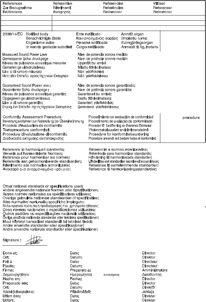
Tomoyasu Kato
Kitamoto, JAPAN |
January 30. 2009 |
||
Kitamoto, JAPAN |
30. Januar 2009 |
||
Kitamoto, JAPAN |
30. Janvier 2009 |
||
Kitamoto, JAPAN |
30. januari 2009 |
||
Kitamoto, JAPAN |
30. gennaio 2009 |
||
Kitamoto, JAPAN |
30. |
|
2009 |
|
|||
|
|||
Kitamoto, JAPAN |
30. enero 2009 |
||
Kitamoto, JAPAN |
30. Janeiro 2009 |
||
Kitamoto, JAPAN |
30. januari 2009 |
||
Kitamoto, JAPAN |
30. tammikuu 2009 |
||
Kitamoto, JAPAN |
30. januar 2009 |
||
Kitamoto, JAPAN |
30. januar 2009 |
||
DC6877

FOREWORD
Thank you very much for purchasing a MAKITA GENERATOR.
This manual covers operation and maintenance of the MAKITA GENERATOR.
This MAKITA GENERATOR can be used for general electrical equipments, appliances, lamps, tools as an AC power source. With regards to DC application, the terminals are used only for charging 12 volt battery.
Never use this generator for any other purposes.
Please take a moment to familiarize yourself with the proper operation and maintenance procedures in order to maximize the safe and ef cient use of this product.
Keep this owner’s manual at hand, so that you can refer to it at any time.
Due to constant efforts to improve our products, certain procedures and speci cations are subject to change without notice.
When ordering spare parts, always give us the MODEL, PRODUCTION NUMBER (PROD No.) and SERIAL NUMBER (SER No.) of your Product.
Please ll in the following blanks after checking the production number on your product. (Location of label is different depending on the product model.)
PROD No. |
|
SER No. |
PROD No. / SER No. (Label)
CONTENTS |
Page |
1. SAFETY PRECAUTIONS . . . . . . . . . . . . . . . . . . . . . . . . . . . . . . . . . . . . . . . . . . . . . . . 2 2. COMPONENTS. . . . . . . . . . . . . . . . . . . . . . . . . . . . . . . . . . . . . . . . . . . . . . . . . . . . . . . 5 3. PRE-OPERATION CHECKS. . . . . . . . . . . . . . . . . . . . . . . . . . . . . . . . . . . . . . . . . . . . . 5 4. OPERATING PROCEDURES . . . . . . . . . . . . . . . . . . . . . . . . . . . . . . . . . . . . . . . . . . . . . . .7 5. WATTAGE INFORMATION. . . . . . . . . . . . . . . . . . . . . . . . . . . . . . . . . . . . . . . . . . . . . 11 6. SPARK ARRESTER . . . . . . . . . . . . . . . . . . . . . . . . . . . . . . . . . . . . . . . . . . . . . . . . . . 12 7. MAINTENANCE SCHEDULE . . . . . . . . . . . . . . . . . . . . . . . . . . . . . . . . . . . . . . . . . . . 13 8. ”HOW-TO” MAINTENANCE . . . . . . . . . . . . . . . . . . . . . . . . . . . . . . . . . . . . . . . . . . . . 14 9. PERIODIC OPERATION AND INSPECTION . . . . . . . . . . . . . . . . . . . . . . . . . . . . . . . 15 10. TRANSPORTING . . . . . . . . . . . . . . . . . . . . . . . . . . . . . . . . . . . . . . . . . . . . . . . . . . . 15 11. PREPARATION FOR STORAGE . . . . . . . . . . . . . . . . . . . . . . . . . . . . . . . . . . . . . . . 16 12. TROUBLESHOOTING . . . . . . . . . . . . . . . . . . . . . . . . . . . . . . . . . . . . . . . . . . . . . . . 16 13. SPECIFICATIONS. . . . . . . . . . . . . . . . . . . . . . . . . . . . . . . . . . . . . . . . . . . . . . . . . . . 17 14. WIRING DIAGRAM . . . . . . . . . . . . . . . . . . . . . . . . . . . . . . . . . . . . . . . . . . . . . . . . . . 18 15. OPTIONAL PARTS . . . . . . . . . . . . . . . . . . . . . . . . . . . . . . . . . . . . . . . . . . . . . . . . . . 20
NOTE Please refer to the illustrations on the back page of the front cover or back cover for Fig.1 to 6 indicated in the sentence.
EN
FR DE NL ES IT PT GR NO SE FI DK RU
1
1. SAFETY PRECAUTIONS
Please make sure you review each precaution carefully.
Pay special attention to statement preceded by the following words.
 WARNING “WARNING” indicates a strong possibility of severe personal injury or loss of life if instructions are not followed.
 CAUTION “CAUTION” indicates a possibility of personal injury or equipment damage if instructions are not followed.
EN FR DE NL ES IT PT GR NO SE FI DK RU
 WARNING
Do not operate the generator near gasoline or gaseous fuel because of the potential danger of explosion or re.
Do not ll the fuel tank with fuel while the engine is running. Do not smoke or use opename near the fuel tank. Be careful not to spill fuel during refueling.
If fuel is spilt, wipe it off and let dry before starting the engine.
 WARNING
Do not place in ammables near the generator.
Be careful not to place fuel, matches, gunpowder, oily cloths, straw, trash, or any other in ammables near the generator.
 WARNING
Do not operate the generator inside a room, cave, tunnel, or other insuf ciently |
|
ventilated area. |
|
Always operate it in a well-ventilated area, otherwise the engine may become |
1m |
overheated, and the poisonous carbon monoxide gas, an odorless, colorless, |
|
|
poison gas, contained in the exhaust gas will endanger human lives. |
1m |
|
Operate generator only outdoors and far from open windows, doors, ventilation |
||
|
||
intakes and other openings. |
|
|
Keep the generator at least 1 meter (3 feet) away , including overhead, from any |
|
|
structure or building use. |
|
 WARNING
Do not enclose the generator nor cover it with a box.
The generator has a built-in forced air cooling system, and may become overheated if it is enclosed.
If generator has been covered to protect it from the weather during non use, be sure to remove it and keep it well away from the area during generator use.
 WARNING
Operate the generator on a level surface.
It is not necessary to prepare a special foundation for the generator.
However, the generator will vibrate on an irregular surface, so choose a level place without surface irregularities. If the generator is tilted or moved during operation, fuel may spill and / or the generator may tip over, causing a hazardous situation.
Proper lubrication cannot be expected if the generator is operated on a steep incline or slope. In such a case, piston seizure may occur even if the oil is above the upper level.
 WARNING
Pay attention to the wiring or extension cords from the generator to the connected device.
If the wire is under the generator or in contact with a vibrating part, it may break and possibly cause a re, generator burnout, or electric shock hazard.
Replace damaged or worn cords immediately.
2

 WARNING
Do not operate in rain, in wet or damp conditions, or with wet hands.
The operator may suffer severe electric shock if the generator is wet due to rain or snow.
 WARNING
If wet, wipe and dry it well before starting. Do not pour water directly over the generator, nor wash it with water.
 WARNING
Be extremely careful that all necessary electrical grounding procedures are followed during each and every use. Failure to do so can be fatal.
 WARNING
Do not contact the generator to a commercial power line. Connection to a commercial power line may short circuit the generator and ruin it or cause electric shock hazard.
Use the transfer switch for connecting to domestic circuit.
 WARNING
No smoking while handling the battery. The battery emits ammable hydrogen gas, which can explode if exposed to electric arcing or open ame.
Keep the area well-ventilated and keep open ames/sparks away when handling the battery.
 WARNING
Engine becomes extremely hot during and for some time after operation. Keep combustible materials well away from generator area.
Be very careful not to touch any parts of the hot engine especially the muf er area or serious burns may result.
 WARNING
Keep children and all bystanders at a safe distance from work areas.
 WARNING
It is absolutely essential that you know the safe and proper use of the power tool or appliance that you intend to use. All operators must read, understand and follow the tool/appliance owners manual. Tool and appliance applications and limitations must be understood. Follow all directions given on labels and warnings. Keep all instruction manuals and literature in a safe place for future reference.
 WARNING
Use only “LISTED” extension cords.
When a tool or appliance is used outdoors, use only extension cords marked “For Outdoor Use”. Extension cords, when not in use should be stored in a dry and well ventilated area.
EN FR DE NL ES IT PT GR NO SE FI DK RU
 WARNING
Always switch off generator’s AC circuit breaker and disconnect tools or appliances when not in use, before servicing, adjusting, or installing accessories and attachments.
 CAUTION
Make sure the engine is stopped before starting any maintenance, servicing or repair.
Make sure maintenance and repair of the generator set are performed by properly trained personnel only.
3

EN FR DE NL ES IT PT GR NO SE FI DK RU
4
2. COMPONENTS
(See Fig. 1)
NOTE
Please refer to the illustrations on the back page of the front cover or back cover for Fig.1 to 6 indicated in the sentence.
EG241A, EG321A, EG321AE,
EG441A, EG441AE (See Fig. 1- )
RECOIL STARTER
RECOIL STARTER HANDLE
FUEL STRAINER (FUEL VALVE)
FUEL TANK
ENGINE SWITCH
CONTROL PANEL
OIL GAUGE (OIL FILLER)
OIL DRAIN PLUG
FUEL GAUGE
0 TANK CAP
1 SPARK PLUG CAP
2 CHOKE LEVER
3 AIR CLEANER
4 EXHAUST OUTLET
5 MUFFLER COVER
EG601A, EG601AE, EG671A, EG671AE
(See Fig. 1- )
RECOIL STARTER
RECOIL STARTER HANDLE
FUEL STRAINER (FUEL VALVE)
TANK CAP
ENGINE SWITCH
CONTROL PANEL
OIL GAUGE (OIL FILLER)
OIL DRAIN PLUG
FUEL TANK
0 FUEL GAUGE
1 CHOKE LEVER
2 SPARK PLUG CAP
3 AIR CLEANER
4 MUFFLER
5 EXHAUST OUTLET
3. PRE-OPERATION CHECKS
(See Fig. 2)
1. CHECK ENGINE OIL (See Fig. 2- , )
Before checking or re lling oil, be sure generator is located on stable and level surface with engine stopped.
Remove oil ller cap and check the engine oil level. (See Fig.2- )
OIL GAUGE |
|
|
|
||
OIL FILLER |
|
|
|
||
|
|
EN |
|||
UPPER LEVEL |
|
|
|||
LOWER LEVEL |
|
|
FR |
||
If oil level is below the lower level line, re ll with |
|||||
DE |
|||||
suitable oil (see table) to upper level line. Do not |
|||||
screw in the oil ller cap when checking oil level. |
NL |
||||
(See Fig.2- ) |
|
|
|||
|
|
ES |
|||
UPPER LEVEL |
|
|
|||
LOWER LEVEL |
|
|
IT |
||
Change oil if contaminated. |
|
|
PT |
||
(See “How-To” Maintenance.) |
|
|
GR |
||
|
|
|
|
||
|
Oil capacity (Upper level) : |
(L) |
|
||
|
NO |
||||
|
EG241A . . . . . . . . . . . . . . . . . . . . . . . . 0.6 |
||||
|
SE |
||||
|
EG321A, EG321AE . . . . . . . . . . . . . . |
0.6 |
|
||
|
EG441A, EG441AE . . . . . . . . . . . . . . |
1.0 |
|
FI |
|
|
EG601A, EG601AE . . . . . . . . . . . . . . |
1.2 |
|
||
|
EG671A, EG671AE . . . . . . . . . . . . . . |
1.2 |
|
DK |
|
|
|
|
|
||
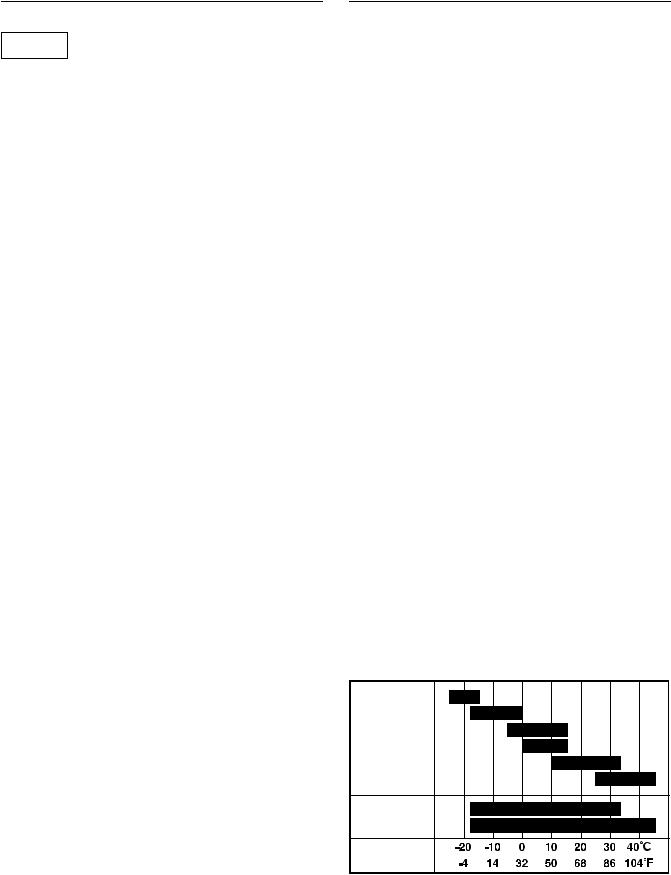
Recommended engine oil: |
RU |
|
Use 4-stroke automotive detergent oil of API service class SE or highergrade (SG, SH or SJ is recommended). SAE 10W-30 or 10W-40 is recommended for general, all-temperature use.
If single viscosity oil is used, select the appropriate viscosity for the average temperature in your area.
5W
10W
20W
Single grade
#20
#30
#40
10W-30 Multigrade 


10W-40
Ambient temperature
5

2. CHECK ENGINE FUEL (See Fig. 2- , )
|
|
|
WARNING |
|
|
|
|
Do not refuel while smoking or near open |
|||
|
|
ame or other such potential re hazards. |
|||
|
|
Otherwise re accident may occur. |
|
|
|
|
|
|
|
|
|
|
|
Check fuel level at fuel level gauge (See Fig.2- ) |
|||
|
|
If fuel level is low, re ll with unleaded automotive |
|||
|
|
gasoline. |
|
|
|
EN |
|
Be sure to use the fuel lter screen on the fuel lter |
|||
|
|||||
FR |
|
neck. (See Fig.2- ) |
|
|
|
DE |
|
LEVEL |
|
|
|
NL |
|
FUEL TANK CAP |
|
|
|
|
FUEL FILTER SCREEN |
|
|
||
ES |
|
|
|
||
|
|
|
|
|
|
IT |
|
|
|
|
|
|
|
Fuel Amount |
|
|
|
PT |
|
|
up to “LEVEL” position : |
(L) |
|
GR |
|
|
EG241A . . . . . . . . . . . . . . . . . . . . . . . 12.8 |
||
|
|
EG321A, EG321AE . . . . . . . . . . . . . |
12.8 |
|
|
NO |
|
|
EG441A, EG441AE . . . . . . . . . . . . . |
12.8 |
|
SE |
|
|
EG601A, EG601AE . . . . . . . . . . . . . |
22.0 |
|
|
|
EG671A, EG671AE . . . . . . . . . . . . . |
22.0 |
|
|
FI |
|
|
|
|
|
DK |
|
|
|
|
|
|
|
WARNING |
|
|
|
RU |
|
|
|
|
|
|
Make sure you review each warning in order to |
||||
|
|
||||
|
|
prevent re hazard. |
|
|
|
Do not rell tank while engine is running or hot.
Close fuel cock before refueling with fuel.
Be careful not to admit dust, dirt, water or other foreign objects Into fuel.
Wipe off spilt fuel thoroughly before starting engine.
Keep open ames away.
3.CHECKING COMPONENT PARTS
Check following items before starting engine:
Fuel leakage from fuel hose, etc.
Bolts and nuts for looseness.
Components for damage or breakage.
Generator not resting on or against any adjacent wiring.
4. CHECK GENERATOR SURROUNDINGS
 WARNING
Make sure you review each warning in order to prevent re hazard.
Keep area clear of in ammables or other hazardous materials.
Keep generator at least 3 feet (1 meter) away from buildings or other structures.
Only operate generator in a dry, well ventilated area.
Keep exhaust pipe clear of foreign objects.
Keep generator away from open ame. No smoking!
Keep generator on a stable and level surface.
Do not block generator air vents with paper or other material.
5.GROUNDING THE GENERATOR
To ground the generator to the earth, connect the grounding lug of the generator to the grounding spike driven into the earth or to the conductor which has been already grounded to the earth. (See Fig.2- )
GROUNDING SPIKE
If such grounding conductor or grounding electrode is unavailable, connect the grounding lug of the generator to the grounding terminal of the using electric tool or appliance. (See Fig.2- )
GROUND TERMINAL
6.BATTERY INSTALLATION (See Fig. 2- ) (Electric Starter Model)
Recommended Battery
Type |
; Lead-acid battery |
Capacity |
|
(Ah/5hr) |
; 12V-21AH or more |
Size |
; Less than 185(L) x 125(W) x 160(H) mm |
|
|
EARTH CABLE(BLACK)
STARTER CABLE(RED)
SETTING PLATE
SETTING BOLT
BATTERY PLATE
BATTERY FRAME #1
BATTERY FRAME #2
PROTECTION PLATE
BOLT
0 NUT
6

 WARNING
Death, personal injury and/or property damage may occur unless instructions are followed carefully.
Use battery of recommended capacity.
Turn the starter switch to the “ ” (STOP) position when mounting or dismounting battery. When mounting battery, connect the positive (+) cable rst and then the negative (-) cable to the battery. Be careful not to short battery cables. When dismounting battery, disconnect negative (-) cable rst.
RED CABLE : To positive (+) terminal BLACK CABLE : To negative (-) terminal
Should the connection be made in incorrect manner, the generator will be broken.
Tighten bolts and nuts on terminals securely so they will not be loosened by vibration.
Disconnect battery cables when charging battery.
4.OPERATING PROCEDURES
(See Fig. 3)
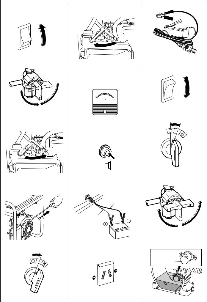
1. STARTING THE GENERATOR
 CAUTION
Check the oil level before each operations as outlined by the article “CHECK ENGINE OIL”
(a)Turn the Engine switch to the position “ | ” (ON). (See Fig.3- )
“ | ” (ON)“ ” (OFF)
(b)Open the fuel valve. (See Fig.3- )
OPEN
CLOSE
(c)Set choke lever to close if the engine is cold. (See Fig.3- )
CHOKE LEVERCLOSE
OPEN
(d)[Recoil starter model]
Pull the starter handle slowly until passing the compression point (resistance will be felt), then return the handle to its original position
and pull briskly. (See Fig.3- )
PULL BRISKLY
If the engine fails to start after several attempts, repeat above procedures with choke lever returned to “OPEN” position.
Do not fully pull out the rope.
After starting, allow the starter handle to return to |
EN |
|||
FR |
||||
its original position while still holding the handle. |
||||
(e) [Electric starter model] |
DE |
|||
Insert the key into the key switch and turn it |
NL |
|||
clockwise to the “ | ” (RUN) position to start the |
||||
engine. |
ES |
|||
Then turn the key further to the “ ” (START) |
||||
IT |
||||
position. |
||||
The engine will be started by starting motor. |
PT |
|||
(See Fig.3- ) |
||||
“ ” (STOP) |
GR |
|||
“ |
| ” (RUN) |
NO |
||
“ |
” (START) |
|||
SE |
||||
|
|
|
||
|
|
|
FI |
|
|
CAUTION |
|
||
|
|
DK |
||
Do not run the starting motor over 5 seconds |
||||
RU |
||||
continuously. |
|
|||
If the engine fails to start, return the key to |
|
|||
the “ | ” (RUN) position and wait about 10 |
|
|||
seconds then start again. |
|
|||
Do not turn the key switch to “  ” (START) position when the engine is running to prevent damage of starting motor.
When starting the engine by recoil starter, set the key switch at the “ | ” (RUN) position and pull the starter handle.
(f)After the engine started, return the choke lever gradually to “OPEN” position.
(See Fig.3- )
CHOKE LEVERCLOSE
OPEN
(g)Warm up the engine without a load for a few minutes.
7

2. USING ELECTRIC POWER
 WARNING
Make sure that the appliance is switched OFF before connecting it to the generator.
Do not move the generator while it is running.
Be sure to ground the generator if the connected appliance is grounded. Failure to ground unit may lead to electrical shock.
CONTROL PANEL
EN FR DE NL ES IT PT GR NO SE FI DK RU
(EG241A, EG321A, EG321AE)
AC receptacle 20A |
Volt meter |
AC circuit breaker
[Electric starter model]
Key switch

Engine switch |
DC circuit |
|
breaker |
Earth (ground) terminal |
DC receptacle |
(EG441A, EG441AE, EG601A, EG601AE, EG671A, EG671AE )
AC receptacle 20A |
Volt meter |
AC circuit |
|
breaker |
|
[Electric starter model]
Key switch

DC circuit
breaker
Engine switch
Earth (ground) terminal |
DC receptacle |
|
8

(1) AC APPLICATION
(a)Check the voltmeter for proper voltage. (See Fig.4- )
This generator is thoroughly tested and adjusted in the factory.
If the generator does not produce the speci ed voltage, consult your nearest Makita factory or authorized service center.
(b)Turn off the switch (es) of the electrical appliance (s) before connecting to the generator.
(c)Insert the plug (s) of the electrical appliance(s) into the receptacle.
Check the amperage of the receptacles, and be sure not to take a current exceeding the speci ed amperage.
Be sure that the total wattage of all appliances dose not exceed the rated output of the generator.
 CAUTION
Do not put foreign objects into the plug receptacle.
 WARNING
Be sure to ground the generator if the connected electrical device is grounded.
NOTE |
|
|
|
When the AC circuit breaker turns off during |
|
|
|
operation, the generator is over loaded or the |
|
|
|
appliance is defective. |
|
|
|
Stop the generator immediately, check the |
|
|
|
EN |
|||
appliance and / or generator for overloading or |
|
||
|
FR |
||
detect and have repaired as necessary by Makita |
|
||
factory or authorized service center. |
|
DE |
|
|
|
||
|
|
||
(d) Check and con rm whether circuit breaker position |
NL |
||
is “ | ” (ON). (See Fig.4- ) |
ES |
||
“ | ” (ON) |
|||
IT |
|||
(e) Turn on the switch of the appliance. |
|||
PT |
|||
|
|
||
(2) DC APPLICATION |
GR |
||
NO |
|||
(Only for charging 12 volt battery) |
|||
DC receptacle (Only for charging 12 volt battery) |
SE |
||
(See Fig.4- ) |
FI |
||
RED CABLE |
|||
DK |
|||
BLACK CABLE |
|||
For charging 12 voltage battery, 12V-8.3A (100W) of |
RU |
||
|
|||
maximum AC power can be taken out from the DC |
|
||
receptacle by means of the exclusive DC cable. |
|
||
(See Fig.4- ) |
|
||
The exclusive DC cable is come with your generator |
|
||
set (included in the package) (See Fig.4- ). |
|
||
DC Circuit Breaker |
|
||
DC circuit breaker is turned off to shut down the DC |
|
||
power, when the DC is over the usage range or the |
|
||
battery is defective. |
|
||
Check the generator and/or battery for overloading or |
|
||
defect, and turn on the DC circuit breaker after no |
|
||
problem and defect are found out. |
|
||
Connection of exclusive DC cable :
Connect positive (red) clip of DC cable to positive
(+) terminal on battery.
Connect negative (black) clip of DC cable to negative (-) terminal on battery.
9

EN
FR DE NL ES IT PT GR NO SE FI DK RU
Battery Charging Procedures :
1)Stop engine.
2)Remove all connections from battery.
3)Insert the plug of exclusive DC cable into DC receptacle.
4)Connect positive (red) clip of DC cable to positive
(+)terminal on battery, and then connect negative (black) clip of DC cable to negative (-) terminal on battery.
5)Take out all plugs at the battery electrolyte uid
ller ports.
6)Check the electrolyte uid level, and re ll the distilled water as necessary.
7)Start engine.
8)Make sure that the pilot lamp is turned on.
9)Make sure that the DC circuit breaker is in the ON position.
10)Battery charging will be started.
 CAUTION
Do not use both AC and DC output at the same time.
Install correct positive (red) or negative (black) cable to the correct polarity on the battery.
Connect and disconnect DC cable with engine stopped.
An explosive hydrogen gas is discharged through vent holes in the battery during the charging process.
Do not allow spark or open ame around the generator or battery during the charging process.
Electrolyte uid contains sulphuric acid, and so the uid can burn eyes and clothing. Be extremely careful to avoid contact.
If injured, wash the affected area immediately with large quantities of water and consult a doctor for treatment.
Charging time is varied according to the kind of battery and discharged level of battery. Measure the specic gravity of electrolyte uid by means of hydrometer every one hour during battery charging.
Make sure if the DC circuit breaker is not turned off.
Battery charging is completed when the specic gravity is in the range of 1.26 to 1.28.
3. STOPPING THE GENERATOR
(a)Turn off the power switch of the electric equipment and unplug the cord from receptacle of the generator.
(b)Allow the engine about 3 minutes to cool down at no-load before stopping.
(c)[Recoil starter model]
Turn the engine switch to the position “ ” (OFF). (See Fig.4- )
“ | ” (ON)“ ” (OFF)
[Electric starter model]
Turn the key switch to the STOP position. (See Fig.4- )
“ ” (STOP)
“ | ” (RUN)“  ” (START)
(d)Close the fuel valve. (See Fig.4- )
OPEN
CLOSE
4.OIL SENSOR (See Fig. 4- )
OIL SENSOR
(a)The oil sensor detects the fall in oil level in the crankcase and automati-cally stops the engine when the oil level falls below a predetermined level.
(b)When engine has stopped automatically, switch off generator’s AC circuit breaker, and check the oil level.
Re ll engine oil to the upper level as instructed on page 5 and restart the engine.
(c)If the engine does not start by usual starting procedures, check the oil level.
10

5. WATTAGE INFORMATION
Some appliances need a “surge” of energy when starting.
This means that the amount of electrical power needed to start the appliance may exceed the amount needed to maintain its use.
Electrical appliances and tools normally come with a label indicating voltage, cycles / Hz, amperage (amps) and electrical power needed to run the appliance or tool.
Check with your nearest dealer or service center with questions regarding power surge of certain appliances or power tools.
Electrical loads such as incandescent lamps and hot plates require the same wattage to start as is needed to maintain use.
Loads such as uorescent lamps require 1.2 to 2 times the indicated wattage during start-up.
Loads for mercury lamps require 2 to 3 times the indicated wattage during start-up.
Electrical motors require a large starting current. Power requirements depend on the type of motor and its use. EN
Once enough “surge” is attained to start the motor,
the appliance will require only 50% to 30% of the wattage to continue running.
Most electrical tools require 1.2 to 3 times their wattage for running under load during use. For example, a 5,000 watt generator can power a 1800 to 4000 watt electrical tool.
Loads such as submersible pumps and air compressors require a very large force to start. They need 3 to 5 times the normal running wattage in order to start.
For example, a 5,000 watt generator would only be able to drive a 1,000 to 1,700 watt pump.
NOTE
The following wattage chart is general guide only. Refer to your speci c appliance for correct wattage.
To determine the total wattage required to run a particular electrical appliance or tool, multiply the voltage gure of the appliance/tool by the amperage (amps) gure of same. The voltage and amperage (amps) information can be found on a name plate which is normally attached to electrical appliances and tools.
|
|
Applicable Wattage(W) |
|
||
Applications |
EG241A |
EG321A |
EG441A |
EG601A |
EG671A |
|
EG321AE |
EG441AE |
EG601AE |
EG671AE |
|
|
|
||||
Incandescent lamp, Heater |
2000 |
2400 |
3600 |
4600 |
5500 |
Fluorescent lamp, Electric tool |
1100 |
1300 |
2000 |
2550 |
3050 |
Mercury lamp |
800 |
950 |
1450 |
1850 |
2200 |
Pump, Compressor |
500 |
600 |
900 |
1150 |
1400 |
FR DE NL ES IT PT GR NO SE FI DK RU
VOLTAGE DROP IN ELECTRIC EXTENSION CORDS
When a long electric extension cord is used to connect an appliance or tool to the generator, a certain amount of voltage drop or loss occurs in the extension cord which reduces the effective voltage available for the appliance or tool. The chart below has been prepared to illustrate the approximate voltage loss when an extension cord of 300 feet (approx. 100 meters) is used to connect an appliance or tool to the generator.
Nominal |
|
Allowable |
No.of strands |
|
|
|
|
|
|
|
|
cross |
A.W.G. |
Resistance |
|
|
Current Amp. |
|
|
||||
current |
/ strands dia. |
|
|
|
|
||||||
section |
|
|
|
|
|
|
|
|
|
|
|
mm2 |
No. |
A |
No./mm |
Ω /100m |
1A |
3A |
5A |
8A |
10A |
12A |
15A |
|
|
|
|
|
|
|
|
|
|
|
|
0.75 |
18 |
7 |
30/0.18 |
2.477 |
2.5V |
8V |
12.5V |
─ |
─ |
─ |
─ |
|
|
|
|
|
|
|
|
|
|
|
|
1.27 |
16 |
12 |
50/0.16 |
1.486 |
1.5V |
5V |
7.5V |
12V |
15V |
18V |
─ |
|
|
|
|
|
|
|
|
|
|
|
|
2.0 |
14 |
17 |
37/0.26 |
0.952 |
1V |
3V |
5V |
8V |
10V |
12V |
15V |
|
|
|
|
|
|
|
|
|
|
|
|
3.5 |
12 to 10 |
23 |
45/0.32 |
0.517 |
─ |
1.5V |
2.5V |
4V |
5V |
6.5V |
7.5V |
|
|
|
|
|
|
|
|
|
|
|
|
5.5 |
10 to 8 |
35 |
70/0.32 |
0.332 |
─ |
1V |
2V |
2.5V |
3.5V |
4V |
5V |
|
|
|
|
|
|
|
|
|
|
|
|
Voltage drop
11
6. SPARK ARRESTER
EN FR DE NL ES IT PT GR NO SE FI DK RU
In a dry or wooded area, it is recommendable to use the product with a spark arrester. Some areas require the use of a spark arrester. Please check your local laws and regulations before operating your product.
The spark arrester must be cleaned regularly to keep it functioning as designed.
A clogged spark arrester :
Prevents the ow of exhaust gasReduces engine outputIncreases fuel consumptionMakes starting dif cult
If the engine has been running, the muf er and the spark arrester will be very hot. Allow the muf er to cool before cleaning the spark arrester.
How to remove the spark arrester
1.Remove the ange bolts from the muf er cover and remove the muf er cover.
2.Remove the special screw from the spark arrester and remove the spark arrester from the muf er.
EG601A, EG601AE
EG671A, EG671AE
 Screw
Screw
Muffler
Spark arrester screen
Clean the spark arrester screen
Use a brush to remove carbon deposits from the spark arrester screen.
Be careful to avoid damaging the screen.
The spark arrester must be free of breaks and holes. Replace the spark arrester if it is damaged.
Install the spark arrester, and muf er protector in the reverse order of disassembly.
EG601A, EG601AE EG671A, EG671AE
Spark arrester screen
12

7. MAINTENANCE SCHEDULE
DAILY |
Check oil level. |
|
Check all components according to “PRE-OPERATION CHECKS.” |
||
|
||
|
|
|
EVERY |
Wash cleaner element. -more often if used in dirty or dusty environments. |
|
50 HOURS |
Check spark plug, clean if necessary. |
|
|
|
|
EVERY |
Change engine oil. *-more often if used in dusty or dirty environments. |
|
100 HOURS |
Clean spark arrester. |
|
|
|
|
EVERY |
Adjust spark plug gap. |
|
200 HOURS |
Clean fuel strainer. |
|
|
|
|
EVERY |
Replace spark plug and cleaner element. |
|
Clean and adjust carburetor,valve clearance, and valve seat along with |
||
500 HOURS |
cylinder head. |
|
|
Check and replace carbon brushes |
|
|
|
|
|
Inspect control panel parts. |
|
EVERY |
Check rotor and starter. |
|
1,000 HOURS |
Replace engine mount rubber. |
|
(24 MONTHS) |
Overhaul engine. |
|
|
Change fuel lines. |
|
|
|
NOTE : (*)
Initial oil change should be performed after rst twenty (20) hours of use. Thereafter change oil every 100 hours.
Before changing the oil, check for a suitable way to dispose of the old oil. Do not pour it down sewage drains, onto garden soil or into open streams.
Your local zoning or environmental regulations will give you more detailed instructions on proper disposal.
EN FR DE NL ES IT PT GR NO SE FI DK RU
13

8. ”HOW-TO” MAINTENANCE
 CAUTION
Make sure the engine is stopped before starting any maintenance, servicing or repair.
NOTE
It is recommended to use ear protection when performing operation, maintenance and repair of the generator set.
EN
FR ENGINE OIL CHANGE (See Fig. 5- )
DE |
Change engine oil every 100 hours. |
|
NL |
(For new engine, change oil after 20 hours.) |
|
(a) Drain oil by removing the drain plug and the oil ller |
||
ES |
||
cap while the engine is warm. |
||
IT |
OIL DRAIN PLUG |
|
PT |
(b) Reinstall the drain plug and ll the engine with oil |
|
GR |
until it reaches the upper level on the oil ller cap. |
|
NO |
Use fresh and high quality lubricating oil to |
|
SE |
the speci ed level as directed on page 5. If |
|
contaminated or deteriorated oil is used or the |
||
FI |
quantity of the engine oil is not suf cient, the |
|
engine damage will result and its life will be greatly |
||
DK |
shortened. |
|
RU |
SERVICING THE AIR CLEANER |
|
|
||
|
(See Fig. 5- thru ) |
|
|
Maintaining an air cleaner in proper condition is very |
|
|
important. |
|
|
Dirt induced through improperly installed, improperly |
|
|
serviced or inadequate elements damages and wears |
|
|
out engines. Keep the element always clean. |
BASE
ELEMENT
AIR CLEANER COVER
BOLT
(a)Remove the bolt of air cleaner cover. (EG601A, EG601AE, EG671A, EG671AE) (See Fig.5- )
Remove the air cleaner cover and cleaner element.
(b)Urethane form : Wash urethane form element in kerosene or diesel fuel.
Then saturate the element in a mixture of 3 parts kerosene or diesel fuel and 1 part engine oil. Squeeze the element to remove the mixture and install it in the air cleaner.
NOTE
Instead of washing oil (kerosene), it is possible to wash the urethane foam element in a solution of mild detergent and warm water.
Then rinse the element thoroughly in clean water. Allow the element to dry thoroughly. Soak the element in clean engine oil and squeeze out excess oil.
CLEANING AND ADJUSTING SPARK PLUG
(See Fig. 5- )
(a)If the plug is contaminated with carbon, remove it using a plug cleaner or wire brush.
(b)Adjust the electrode gap to 0.6 to 0.7 mm.
Spark plug : BR-6HS (NGK)
CLEANING FUEL STRAINER
(See Fig. 5- )
Dirt and water in the fuel are removed by the fuel strainer.
(a)Remove the strainer cup and throw away water and dirt.
(b)Clean the screen and strainer cup with gasoline.
(c)Tightly fasten the cup to main body, making sure to avoid fuel leak.
CHECKING CARBON BRUSH
Brush Maintenance Essentials
(Effective Length)
The brush is the area which touches the slip ring, and its surface must be kept smooth.
If it is not smooth then carbon and other substances will adhere between the brush and slip ring.
This must be buffed with sandpaper or the like because it is hazardous.
The usable length of the brush is 5~11mm, so if the brush is 5mm long or less replace it with a new one. (See Fig.5- )
LENGTH WHEN NEW
EFFECTIVE BRUSH LENGTH
14

This is done because if the length of the brush gets any shorter, its contact pressure with the slip ring will decrease, resulting in a drop in generator ef ciency and the output voltage.
Check the brush every 500 hours to con rm its length.
In addition, check the brush length if the generator malfunctions, such as when it is not generating power or its voltage is low.
Brush Maintenance Essentials
(Disassembly and Assembly) (See Fig. 5- )
BRUSHSLIP RING
BRUSH HOLDERFLANGE BOLTSBRACKET COVERFLANGE BOLTS
Disassembly
1.Remove the two ange bolts (M5 x 20), then remove the bracket cover.
2.Remove the two ange bolts (M5 x 16), then remove the brush.
Assembly
1. While pressing the brush against the slip ring, secure it (1.5~2N•m) by tightening it with the twoange bolts (M5 × 16).
When doing so, con rm that the brush is in the proper position relative to the slip ring.
2.Secure the bracket cover (3~4N•m) by tightening it with the two ange bolts (M5 × 20).
(a)Check the fuel (gasoline), engine oil and air cleaner.
(b)Start engine.
(c)With appliance such as lightings activated, run the engine for over ten minutes.
(d)Check for the following items;
Proper engine running.
Adequate output and the indicator lamp turned on properly.
The engine switch normally operated.
No leakage of engine oil and fuel (gasoline).
10. TRANSPORTING
When transporting the generator, make sure that the fuel (gasoline) should be drained from the tank.
 WARNING
To prevent fuel spillage due to the vibration and impact, never transport the generator with the fuel (gasoline) lled in the tank.
Secure the tank cap thoroughly.
To avoid the risk of the gasoline ammability, never leave the generator in an area exposed to direct sunlight or high temperatures for a long time.
Keep the fuel (gasoline) in the exclusive gasoline storage tank made by steel when transporting.
EN FR DE NL ES IT PT GR NO SE FI DK RU
9.PERIODIC OPERATION AND INSPECTION
When furnishing the generator as emergency electric power source, periodic operation and inspection are needed.
Fuel (gasoline) and engine oil will be deteriorated with time, and this causes that the engine is dif cult to start and as the results improper engine operation and fault.
 CAUTION
Since the fuel (gasoline) will be deteriorated with time, replace fuel (gasoline) with fresh one periodically; once every three (3) months is recommended.
(a)Turn the engine switch to the “STOP” position.
(b)Drain the fuel from the tank.
(c)Secure the tank cap.
 CAUTION
Do not place any heavy objects on the generator.
Select and place the generator in the proper position of the transport vehicle so that the generator not be moved or fallen down.
Fix the generator with rope as necessary.
15

11. PREPARATION FOR STORAGE
(See Fig. 6)
EN
FR DE NL ES IT PT GR NO SE FI DK RU
The following procedures should be followed prior to storage of your generator for periods of 6 months or longer.
Drain fuel from fuel tank carefully by disconnecting the fuel line.
Gasoline left in the fuel tank will eventually deteriorate making engine-starting dif cult.
Remove the carburetor oat chamber and also drain the carburetor. (See Fig.6- )
DRAIN SCREW
Change engine oil.
Check for loose bolts and screws, tighten them if necessary.
Clean generator thoroughly with oiled cloth. Spray with preservative if available.
NEVER USE WATER TO CLEAN GENERATOR !
Pull starter handle until resistance is felt, leaving handle in that position.
Store generator in a well ventilated, low humidity area.
12. TROUBLESHOOTING
When generator engine fails to start after several attempts, or if no electricity is available at the output socket, check the following chart. If your generator still fails to start or generate electricity, contact your nearest Makita factory or authorized service center for further information or corrective procedures.
When Engine Fails to Start:
Check if choke lever is in its proper position.
Check if fuel valve is open.
Check fuel level.
Check if engine switch is in OFF.
Check to make sure generator is not connected to an appliance.
Set the choke lever to “CLOSE” position.
If closed, open fuel valve.
If empty, refill fuel tank making sure not to overfill.
Turn engine switch to ON.
If connected, turn off the power switch on the connected appliance and unplug.
Check spark plug for loose spark plug cap. |
|
|
|
If loose, push spark plug cap back into place. |
|
|
|
||
|
|
|
|
|
Check spark plug for contamination. |
|
|
|
Remove spark plug and clean electrode. |
When No Electricity Is Generated at Receptacle:
Check to make sure AC circuit breaker is in the “ON” position.
Check AC receptacle and DC terminals for loose connection.
Check to see if engine starting was attempted with appliances already connected to generator.
Low power.
After making sure that the total wattage of the electrical appliance is within permissible limits and there are no defects in the appliance, turn the AC circuit breaker to the “ON” position.
If breakers continue to actuate, consult your nearest servicing dealer.
Secure connection if necessary.
Turn off switch on the appliance, and disconnect cable from receptacle. Reconnect after generator has been started properly.
Carbon brushes are excessively worn
16

13. SPECIFICATIONS
MODEL |
EG241A |
EG321A |
EG441A |
EG601A |
EG671A |
|
EG321AE |
EG441AE |
EG601AE |
EG671AE |
|||
|
|
|
|
Type |
|
Brush, self-exciting, 2-poles, single phase |
|
||||||||
|
|
|
|
|
|
|
|
|
|
|
|
|
|
|
|
Voltage regulating system |
|
|
|
|
AVR type |
|
|
|
|||
|
|
|
|
|
|
|
|
|
|
|
|
|
|
|
|
AC Output |
|
|
|
|
|
|
|
|
|
|
|
|
|
|
Rated voltage-Frequency |
V-Hz |
|
|
|
|
230 - 50 |
|
|
|
|
|
|
|
|
|
|
|
|
|
|
|
|
|
|
|
|
|
Rated current |
A |
8.7 |
|
10.4 |
|
15.7 |
|
20.0 |
|
23.9 |
Generator |
|
|
|
|
|
|
|
|
|
|
|
|
|
|
Rated output |
VA (W) |
2000 |
|
2400 |
|
3600 |
|
4600 |
|
5500 |
||
|
|
|
|
|
|
|
|||||||
|
|
|
|
|
|
|
|
|
|
|
|
|
|
|
|
|
Maximum output |
VA (W) |
2400 |
|
3200 |
|
4400 |
|
6000 |
|
6700 |
|
|
|
|
|
|
|
|
|
|
|
|
|
|
|
|
|
Rated power factor |
|
|
|
|
|
1.0 |
|
|
|
|
|
|
|
|
|
|
|
|
|
|
|
|
||
|
|
|
Safety device type |
|
|
|
Fuse-less circuit breaker |
|
|||||
|
|
|
|
|
|
|
|
|
|
|
|
|
|
|
|
DC Output |
|
|
|
|
|
|
|
|
|
|
|
|
|
|
Rated voltage |
V |
|
|
|
|
12 |
|
|
|
|
|
|
|
|
|
|
|
|
|
|
|
|
|
|
|
|
|
Rated current |
A |
|
|
|
|
8.3 |
|
|
|
|
|
|
|
|
|
|
|
|
|
|
|
|
||
|
|
|
Safety device type |
|
|
|
Fuse-less circuit breaker |
|
|||||
|
|
Model |
|
EX17D |
|
EX21D |
|
EX30D |
|
EX35D |
|
EX40D |
|
|
|
|
|
|
|
|
|
|
|
|
|||
|
|
Type |
|
ROBIN, |
Air-cooled, 4-stroke, OHC, Gasoline Engine |
||||||||
|
|
|
|
|
|
|
|
|
|
|
|
|
|
|
|
Displacement |
mL |
169 |
|
211 |
|
287 |
|
404 |
|
||
|
|
|
|
|
|
|
|
|
|
|
|
|
|
|
|
Fuel |
|
|
|
Automotive |
Unleaded Gasoline |
|
|||||
|
|
|
|
|
|
|
|
|
|
|
|
|
|
Engine |
|
Fuel tank capacity |
L |
|
|
12.8 |
|
|
|
22.0 |
|
||
|
|
|
|
|
|
|
|
|
|
|
|
|
|
|
Engine oil capacity |
L |
0.6 |
|
|
1.0 |
|
1.2 |
|
||||
|
|
|
|
|
|
||||||||
|
|
|
|
|
|
|
|
|
|
|
|
|
|
|
|
Rated continuous operation |
H |
10.5 |
|
9.0 |
|
5.6 |
|
7.5 |
|
6.6 |
|
|
|
|
|
|
|
|
|
|
|
|
|
|
|
|
|
Spark plug |
|
|
|
BR-6HS (NGK) |
|
|
|
||||
|
|
|
|
|
|
|
|
|
|
|
|
|
|
|
|
Starting system |
|
Recoil |
|
|
|
Electric starter / Recoil |
|
||||
|
|
|
starter |
|
|
|
|
||||||
|
|
|
|
|
|
|
|
|
|
|
|
|
|
|
|
3/4Load Fuel consumption |
L/H |
1.0 |
|
1.3 |
|
1.9 |
|
2.7 |
|
2.9 |
|
|
|
|
|
|
|
|
|
|
|
|
|
|
|
Direction of rotation |
|
|
|
Counter - clockwise |
|
|
|
||||||
|
|
|
|
|
|
|
|
|
|
|
|
|
|
Dimension |
Length |
mm |
600 |
|
620 |
|
675 |
|
725 |
|
|||
|
(870)*1 |
|
(925)*1 |
|
(975)*1 |
||||||||
|
|
|
|
|
|
|
|||||||
|
|
|
|
|
|
|
|
|
|||||
|
|
Width |
mm |
420 |
|
450 |
|
510 |
|
530 |
|
||
|
|
|
|
|
|
|
|
|
|
|
|
|
|
|
|
Height |
mm |
500 |
|
500 |
|
540 |
|
580 |
|
||
|
|
|
|
|
|
|
|
|
|
|
|
|
|
Dry weight |
kg |
47 |
|
51 |
|
67 |
|
86 |
|
88 |
|||
|
(56)*2 |
|
(77)*2 |
|
(96)*2 |
|
(98)*2 |
||||||
|
|
|
|
|
|
|
|
|
|
||||
Gross weight |
kg |
57 |
|
61 |
|
78 |
|
104 |
|
106 |
|||
Weight according to EPTA procedure 01/2003 |
|
(66)*2 |
|
(88)*2 |
|
(114)*2 |
|
(116)*2 |
|||||
|
|
|
|
|
|
||||||||
|
|
|
|
|
|
|
|
|
|
|
|
|
|
EN
FR DE NL ES IT PT GR NO SE FI DK RU
Specifications are subject to change without notice.
*1: ( ) shows dimensions with Battery frame. *2: ( ) shows weight with Electric starter.
17

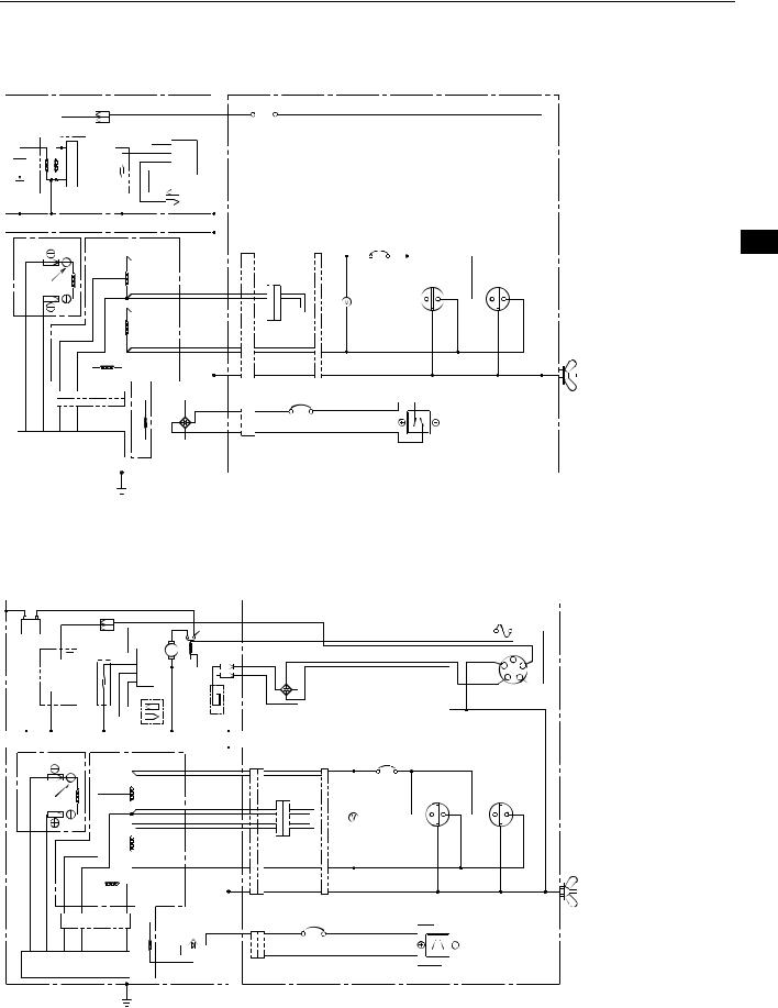
14. WIRING DIAGRAM
EG241A, EG321A (50Hz-230V) [Recoil starter model]
ENGINE |
CONTROL BOX |
|
Blk |
Spark plug |
Ignition coil |
Oil sensor switch
 Org
Org
Blk
Y

Y/R 

Blk  Grn
Grn
Engine switch
Oil sensor unit
EN FR DE NL ES IT PT GR NO SE FI DK RU
GENERATOR
ROTOR |
|
STATOR |
|
R |
R |
Noise filter |
|||
|
|
|
|
|
|
|
|
||
|
Slip |
|
|
|
AC |
|
|
|
|
|
|
|
|
winding 1 |
|
|
Voltmeter |
||
Y |
Blu |
|
|
|
|
|
|||
|
ring |
|
|
|
|
|
Gry |
Gry |
|
|
|
|
|
|
|
|
|
||
|
|
|
|
|
AC |
|
Org |
Gry |
|
|
|
|
|
|
|
|
|
|
|
|
|
|
|
|
winding 2 |
Blu |
Blu |
|
|
|
|
|
|
|
|
|
|
||
|
Brn |
Blu |
Sub coil |
|
|
Grn |
Grn |
|
|
|
Y |
|
Y |
Brn |
DC circuit |
||||
|
|
|
|
|
winding |
|
|
||
|
Brn |
Blu |
Y |
Y |
|
|
breaker |
||
|
Bridge |
W |
W |
||||||
|
|
|
|
|
|
||||
|
|
|
|
|
|
|
|||
|
|
|
|
|
|
diode |
Blk |
Blk |
|
|
|
|
|
|
DC |
|
|
||
|
AVR unit |
|
|
Brn |
|
|
|
||
|
|
|
|
|
|
|
|||
|
|
|
|
|
|
|
|
|
|
 Grn/Y
Grn/Y
EG321AE (50Hz-230V) [Electric starter model]
ENGINE
Blk |
R |
Blk |
|
|
Blk |
|
|
Battery |
Blk |
StarterElectric |
|
Sparkplug |
Ignitioncoil sensorOil switch |
Oilsensorunit |
|
|
|
Org |
|
Y

Y/R 

CONTROL BOX
switch |
|
Blu |
Gry |
|
Grn |
||
|
|
||
Magnetic |
Charge coil |
|
|
Blu |
|
||
|
|
|
AC circuit breaker
R |
|
AC Output |
AC Output |
receptacle |
receptacle |
DC Output
W receptacle


 DC12V
DC12V
R |
Org Fuse |
Org |
|
|
|
Blk |
Grn M- |
ST |
M+
Gry IG 
B
Key switch
Grn
GENERATOR
|
|
|
|
|
|
|
|
|
AC circuit |
|
|
ROTOR |
|
STATOR |
|
|
R |
R Noise filter |
breaker |
R |
|
||
|
Slip |
|
|
|
AC |
|
|
|
|
AC Output |
AC Output |
|
|
|
|
|
|
|
Voltmeter |
receptacle |
receptacle |
||
Y |
ring |
|
|
|
winding 1 |
Gry |
Gry |
|
|
||
Blu |
|
|
|
|
|
|
|
||||
|
|
|
|
|
|
|
|
|
|
||
|
|
|
|
|
AC |
|
Org |
Gry |
|
|
|
|
|
|
|
|
|
|
|
|
|
|
|
|
|
|
|
|
winding 2 |
Blu |
Blu |
|
|
|
|
|
|
|
Sub coil |
|
|
|
|
|
|||
|
Brn |
Blu |
|
|
Grn |
Grn |
|
|
|
||
|
Y |
Y |
|
|
|
|
|||||
|
|
|
|
|
winding |
Brn |
|
DC circuit |
|
DC Output |
|
|
Brn |
Blu |
Y |
Y |
|
W breaker |
|
|
|||
|
Bridge |
W |
W |
DC12V |
|
||||||
|
|
|
|
|
|
receptacle |
|
||||
|
|
|
|
|
|
diode |
Blk |
Blk |
|
|
|
|
|
|
|
|
DC |
|
|
|
|
||
|
AVR unit |
|
Brn |
|
|
|
|
|
|||
|
|
|
|
|
|
|
|
||||
|
|
|
|
|
|
|
|
|
|
|
|
 Grn/Y
Grn/Y
Wiring color code
Blk |
: Black |
Blk/W |
: Black/White |
Blu |
: Blue |
LBlu |
: Light blue |
Brn |
: Brown |
Brn/W : Brown/White |
|
Grn |
: Green |
Grn/W : Green/White |
|
Org |
: Orange |
Gry |
: Gray |
R: Red
W |
: White |
Y |
: Yellow |
W/Blk |
: White/Black |
Grn/Y |
: Green/Yellow |
Pur |
: Purple |
Earth (Ground) terminal
Earth (Ground) terminal
18
EG441A, EG601A, EG671A (50Hz-230V) [Recoil starter model]
ENGINE
|
Blk |
|
Spark plug |
Ignition coil |
Oil sensor switch |
Org  Blk
Blk
Y

Y/R 

Oil sensor unit
GENERATOR
ROTOR |
|
STATOR |
|
R |
||
|
|
|
|
|
|
|
|
Slip |
|
|
AC |
|
|
|
ring |
|
|
winding 1 |
Gry |
|
W |
R |
|
|
AC |
|
Org |
|
|
|
|
|||
|
|
|
|
winding 2 |
Blu |
|
|
|
|
|
|
|
|
|
Grn |
W |
Sub coil |
|
Grn |
|
|
Blu |
Blu |
|
|||
|
Grn |
W |
Blu Blu |
winding |
Brn |
Blk |
|
Bridge |
|||||
|
|
|
|
|
W |
|
|
|
|
|
|
diode |
|
|
AVR unit |
|
DC |
Brn |
|
|
|
|
|
|
Grn/Y |
|
|
CONTROL BOX
Blk  Grn
Grn
Engine switch
|
|
AC circuit |
|
|
R |
Noise filter |
breaker R |
|
|
|
|
AC Output |
AC Output |
|
|
Org |
receptacle |
receptacle |
|
|
Voltmeter |
|
||
|
Gry |
|
|
|
Blu |
|
|
|
|
Grn |
|
|
|
|
|
DC circuit |
DC Output |
|
|
|
breaker |
Earth |
||
W |
receptacle |
|||
W |
||||
|
|
|
(Ground) |
|
Blk |
|
DC12V |
terminal |
|
|
|
|
Wiring color code
Blk |
: Black |
Blk/W |
: Black/White |
Blu |
: Blue |
LBlu |
: Light blue |
Brn |
: Brown |
Brn/W : Brown/White |
|
Grn |
: Green |
Grn/W : Green/White |
|
Org |
: Orange |
Gry |
: Gray |
R: Red
W |
: White |
Y |
: Yellow |
W/Blk |
: White/Black |
Grn/Y |
: Green/Yellow |
Pur |
: Purple |
EG441AE, EG601AE, EG671AE (50Hz-230V) [Electric starter model]
ENGINE
Blk R
Battery plugSpark


Blk |
Blk |
|
Ignitioncoil sensorswitch |
Blk |
Electric |
sensorOil unit |
||
|
Org |
|
Oil |
Y |
|
Y/R |
|
|
|
|
Starter |
Magnetic switch |
Charge coil |
GENERATOR
ROTOR |
|
STATOR |
|
R |
||
|
|
|
|
|
|
|
|
Slip |
|
|
AC |
|
|
|
ring |
|
|
winding 1 |
Gry |
|
|
|
|
|
AC |
|
Org |
W |
R |
|
|
|
|
|
|
|
winding 2 |
Blu |
|||
|
|
|
|
|
|
|
|
Grn |
|
Sub coil |
|
|
Grn |
|
W |
Blu |
Blu |
|
||
|
|
|
||||
|
|
|
|
|
||
|
Grn |
W |
Blu Blu |
winding |
Brn |
Blk |
|
Bridge |
|||||
|
|
|
|
|
W |
|
|
|
|
|
|
diode |
|
|
AVR unit |
|
DC |
Brn |
|
|
|
|
|
|
Grn/Y |
|
|
CONTROL BOX
|
|
R |
Org |
Fuse |
Org |
|
|
|
|
|
|
Blu |
Gry |
Blk |
Grn |
M- |
ST |
Grn |
|
|
|
M+ |
|
|
|
Gry |
IG |
||
|
|
|
B |
||
|
|
|
|
|
|
|
|
|
Grn |
Key switch |
|
Blu |
|
|
|
|
|
|
|
|
|
|
|
|
|
AC circuit |
|
|
|
R |
Noise filter |
breaker R |
|
|
|
|
|
AC Output |
AC Output |
||
|
Gry |
receptacle |
receptacle |
||
|
Voltmeter |
|
|
|
|
|
Org |
|
|
|
|
|
|
|
|
|
|
Blu |
|
|
|
|
|
Grn |
|
|
|
|
|
|
DC circuit |
DC Output |
|
Earth |
|
|
breaker |
|
|||
W |
receptacle |
|
(Ground) |
||
W |
|
||||
|
terminal |
Blk |
DC12V |
|
EN
FR DE NL ES IT PT GR NO SE FI DK RU
19
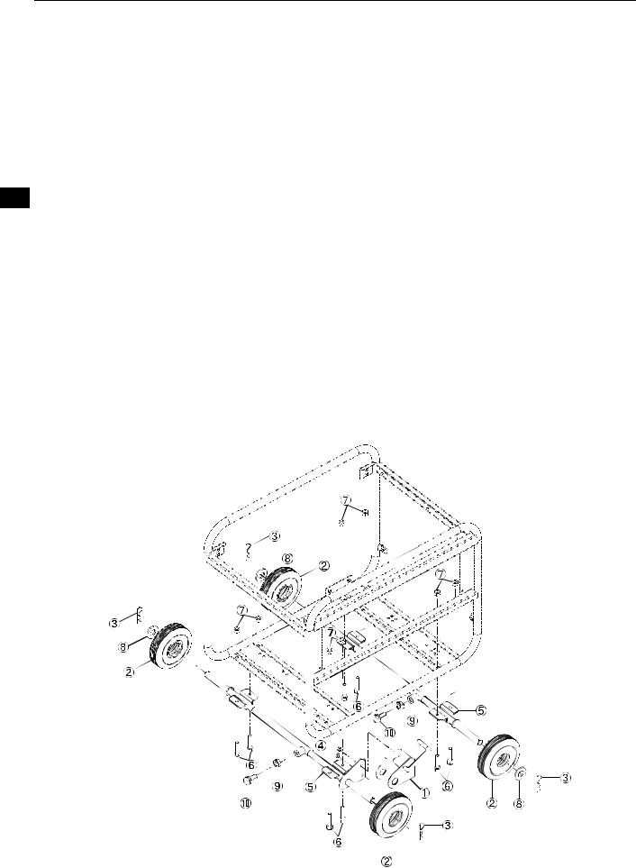
15. OPTIONAL PARTS
EN
FR DE NL ES IT PT GR NO SE FI DK RU
Wheel Kit Installation
(1)Check the supplied accessories
(2)Tool preparation
Crane or square bar (about 100mm by 100mm)
Pliers
2 sets of spanners (12mm)
(3)Installation procedures
A)Raise the generator about 100mm with the crane or square bar.
B)Install the wheel and stopper in the wheel shaft.
<Stopper section>
Install wheel shaft into stopper so that wheel is inserted between them and fasten with pin . Next, tighten wheel shaft and stopper with nut .
<Non-stopper section>
Install wheel and washer onto wheel shaft and fasten with pin .
C)Check that the wheel rotates smoothly.
D)Loosen length adjustment nut for wheel shaft and bolt , then align the position of the hole on the frame with the mounting hole of wheel shaft and tighten bolt and nut to x this in place.
Tightening torque: 20 to 25N-m (2.0 to 2.5kg-m)
E) Tighten length adjustment nut for wheel shaft and bolt to x the length of wheel shaft .
20

AVANT-PROPOS
Nous vous remercions d’avoir acquis un GROUPE ÉLECTROGÈNE MAKITA.
Ce manuel décrit le fonctionnement et l’entretien du GROUPE ÉLECTROGÈNE MAKITA.
Ce GROUPE ÉLECTROGÈNE MAKITA peut être utilisé pour les équipements électriques généraux, appareils électriques, lampes, outils, comme source de courant alternatif. Quant à l’application à C.C., les bornes sont utilisées seulement pour charger la batterie de 12 volts. Ne jamais utiliser ce groupe électrogène pour aucun autre but.
Prenez quelques instants pour vous familiariser avec les procédures de fonctionnement et d’entretien a n d’utiliser ce produit dans les meilleures conditions possibles de sécurité et de performance.
Conservez ce manuel à portée de main pour vous y reporter lorsque cela est nécessaire.
Dans le souci d’une amélioration constante de la qualité de nos produits, nous ous réservons le droit de procéder sans préavis à la modi cation de certains processus et de certaines caractéristiques.
À la commande de pièces de rechange, veuillez toujours nous indiquer le MODÈLE, le NUMÉRO DE PRODUCTION et le NUMÉRO DE SÉRIE de votre produit.
Veuillez compléter les parties en blanc suivantes après véri cation du numéro de production indiqué sur votre produit.
(L’emplacement de l’étiquette varie selon le modèle de produit).
PROD No. |
SER No. |
Nº. DE PROD. / Nº. DE SÉR. (Étiquette)
TABLE DES MATIÈRES |
Page |
1. PRÉCAUTIONS DE SÉCURITÉ . . . . . . . . . . . . . . . . . . . . . . . . . . . . . . . . . . . . . . . . . . 2 2. COMPOSANTS . . . . . . . . . . . . . . . . . . . . . . . . . . . . . . . . . . . . . . . . . . . . . . . . . . . . . . . 5 3. CONTRÔLES PRÉ-OPÉRATOIRES. . . . . . . . . . . . . . . . . . . . . . . . . . . . . . . . . . . . . . . 5 4. MODES OPÉRATOIRES . . . . . . . . . . . . . . . . . . . . . . . . . . . . . . . . . . . . . . . . . . . . . . . 7 5. INFORMATION D’ALIMENTATION EN WATTS. . . . . . . . . . . . . . . . . . . . . . . . . . . . . 11 6. INTERCEPTEUR D’ÉTINCELLE. . . . . . . . . . . . . . . . . . . . . . . . . . . . . . . . . . . . . . . . . 12 7. PROGRAMME D’ENTRETIEN . . . . . . . . . . . . . . . . . . . . . . . . . . . . . . . . . . . . . . . . . . 13 8. ENTRETIEN “COMMENT PROCÉDER”. . . . . . . . . . . . . . . . . . . . . . . . . . . . . . . . . . . 14 9. FONCTIONNEMENT PÉRIODIQUE ET INSPECTION . . . . . . . . . . . . . . . . . . . . . . . 15 10. TRANSPORT . . . . . . . . . . . . . . . . . . . . . . . . . . . . . . . . . . . . . . . . . . . . . . . . . . . . . . 15 11. PRÉPARATION AU MAGASINAGE . . . . . . . . . . . . . . . . . . . . . . . . . . . . . . . . . . . . . 16 12. DÉPANNAGE . . . . . . . . . . . . . . . . . . . . . . . . . . . . . . . . . . . . . . . . . . . . . . . . . . . . . . 16 13. FICHE TECHNIQUE . . . . . . . . . . . . . . . . . . . . . . . . . . . . . . . . . . . . . . . . . . . . . . . . . 17 14. DIAGRAMME DE CÂBLAGE . . . . . . . . . . . . . . . . . . . . . . . . . . . . . . . . . . . . . . . . . . 18 15. PIÈCES EN OPTION. . . . . . . . . . . . . . . . . . . . . . . . . . . . . . . . . . . . . . . . . . . . . . . . . 20
NOTE Voir les illustrations au dos de la page de couverture ou de la dernière page pour les Fig. 1 à 6 spécifiées dans le texte.
FR DE NL ES IT PT GR NO SE FI DK RU
1
 Loading...