


 Loading...
Service Manual
Models
G10-55A
&
G12-55A AccuPlace
31200452
Original
January 20, 2009
An Oshkosh Corporation Company
EFFECTIVITY PAGE
January 20, 2009 - A - Original Issue Of Manual
31200452 |
G10-55A & G12-55A AccuPlace |
i |
EFFECTIVITY PAGE
-ii |
G10-55A & G12-55A AccuPlace |
31200452 |

SECTION CONTENTS
Section Subject Page
Section 1 |
|
|
Safety Practices . . . . . . . . . . . . . . . . . . . . . . . . . . . . . . . . . . . . . . . . . . . . . . . . . . . . . . . |
1.1 |
|
1.1 |
Introduction . . . . . . . . . . . . . . . . . . . . . . . . . . . . . . . . . . . . . . . . . . . . . . . . . . . . . . . . . . |
1.2 |
1.2 |
Disclaimer . . . . . . . . . . . . . . . . . . . . . . . . . . . . . . . . . . . . . . . . . . . . . . . . . . . . . . . . . . . |
1.2 |
1.3 |
Operation & Safety Manual . . . . . . . . . . . . . . . . . . . . . . . . . . . . . . . . . . . . . . . . . . . . . . |
1.2 |
1.4 |
Do Not Operate Tags . . . . . . . . . . . . . . . . . . . . . . . . . . . . . . . . . . . . . . . . . . . . . . . . . . . |
1.2 |
1.5 |
Safety Information . . . . . . . . . . . . . . . . . . . . . . . . . . . . . . . . . . . . . . . . . . . . . . . . . . . . . |
1.3 |
1.6 |
Safety Instructions . . . . . . . . . . . . . . . . . . . . . . . . . . . . . . . . . . . . . . . . . . . . . . . . . . . . . |
1.3 |
1.7 |
Safety Decals . . . . . . . . . . . . . . . . . . . . . . . . . . . . . . . . . . . . . . . . . . . . . . . . . . . . . . . . . |
1.4 |
Section 2 |
|
|
General Information and Specifications . . . . . . . . . . . . . . . . . . . . . . . . . . . . . . . . . . . . |
2.1 |
|
2.1 |
Replacement Parts and Warranty Information . . . . . . . . . . . . . . . . . . . . . . . . . . . . . . . . |
2.2 |
2.2 |
Torques . . . . . . . . . . . . . . . . . . . . . . . . . . . . . . . . . . . . . . . . . . . . . . . . . . . . . . . . . . . . . |
2.3 |
2.3 |
Specifications . . . . . . . . . . . . . . . . . . . . . . . . . . . . . . . . . . . . . . . . . . . . . . . . . . . . . . . . . |
2.6 |
2.4 |
Fluid and Lubricant Capacities. . . . . . . . . . . . . . . . . . . . . . . . . . . . . . . . . . . . . . . . . . . . |
2.8 |
2.5 |
Service and Maintenance Schedules. . . . . . . . . . . . . . . . . . . . . . . . . . . . . . . . . . . . . . . |
2.9 |
2.6 |
Lubrication Schedules . . . . . . . . . . . . . . . . . . . . . . . . . . . . . . . . . . . . . . . . . . . . . . . . . . |
2.11 |
Section 3 |
|
|
Boom . . |
. . . . . . . . . . . . . . . . . . . . . . . . . . . . . . . . . . . . . . . . . . . . . . . . . . . . . . . . . |
3.1 |
3.1 |
Boom System Component Terminology. . . . . . . . . . . . . . . . . . . . . . . . . . . . . . . . . . . . . |
3.2 |
3.2 |
Boom System - Four Section . . . . . . . . . . . . . . . . . . . . . . . . . . . . . . . . . . . . . . . . . . . . . |
3.3 |
3.3 |
Boom Assembly Maintenance . . . . . . . . . . . . . . . . . . . . . . . . . . . . . . . . . . . . . . . . . . . . |
3.3 |
3.4 |
Boom Extend and Retract Chains . . . . . . . . . . . . . . . . . . . . . . . . . . . . . . . . . . . . . . . . . |
3.9 |
3.5 |
Boom Section Separation Adjustment . . . . . . . . . . . . . . . . . . . . . . . . . . . . . . . . . . . . . . |
3.14 |
3.6 |
Hydraulic Sub-Assembly Removal/Installation. . . . . . . . . . . . . . . . . . . . . . . . . . . . . . . . |
3.14 |
3.7 |
Boom Wear Pads . . . . . . . . . . . . . . . . . . . . . . . . . . . . . . . . . . . . . . . . . . . . . . . . . . . . . . |
3.17 |
3.8 |
Quick Switch Assembly . . . . . . . . . . . . . . . . . . . . . . . . . . . . . . . . . . . . . . . . . . . . . . . . . |
3.18 |
3.9 |
Forks . . . . . . . . . . . . . . . . . . . . . . . . . . . . . . . . . . . . . . . . . . . . . . . . . . . . . . . . . . . . . . . |
3.18 |
3.10 |
Troubleshooting . . . . . . . . . . . . . . . . . . . . . . . . . . . . . . . . . . . . . . . . . . . . . . . . . . . . . . . |
3.19 |
Section 4 |
|
|
Cab and Covers . . . . . . . . . . . . . . . . . . . . . . . . . . . . . . . . . . . . . . . . . . . . . . . . . . . . . . . . |
4.1 |
|
4.1 |
Operator’s Cab and Covers Component Terminology . . . . . . . . . . . . . . . . . . . . . . . . . . |
4.2 |
4.2 |
Operator’s Cab . . . . . . . . . . . . . . . . . . . . . . . . . . . . . . . . . . . . . . . . . . . . . . . . . . . . . . . . |
4.3 |
4.3 |
Cab Components . . . . . . . . . . . . . . . . . . . . . . . . . . . . . . . . . . . . . . . . . . . . . . . . . . . . . . |
4.3 |
4.4 |
Cab Removal . . . . . . . . . . . . . . . . . . . . . . . . . . . . . . . . . . . . . . . . . . . . . . . . . . . . . . . . . |
4.7 |
4.5 |
Cab Installation . . . . . . . . . . . . . . . . . . . . . . . . . . . . . . . . . . . . . . . . . . . . . . . . . . . . . . . |
4.9 |
Section 5 |
|
|
Axles, Drive Shafts, Wheels and Tires . . . . . . . . . . . . . . . . . . . . . . . . . . . . . . . . . . . . . |
5.1 |
|
5.1 |
Axle, Drive Shaft and Wheel Component Terminology . . . . . . . . . . . . . . . . . . . . . . . . . |
5.2 |
5.2 |
General Information . . . . . . . . . . . . . . . . . . . . . . . . . . . . . . . . . . . . . . . . . . . . . . . . . . . . |
5.3 |
5.3 |
Axle Assemblies. . . . . . . . . . . . . . . . . . . . . . . . . . . . . . . . . . . . . . . . . . . . . . . . . . . . . . . |
5.3 |
5.4 |
Drive Shafts . . . . . . . . . . . . . . . . . . . . . . . . . . . . . . . . . . . . . . . . . . . . . . . . . . . . . . . . . . |
5.9 |
5.5 |
Wheels and Tires . . . . . . . . . . . . . . . . . . . . . . . . . . . . . . . . . . . . . . . . . . . . . . . . . . . . . . |
5.10 |
5.6 |
Brakes . . . . . . . . . . . . . . . . . . . . . . . . . . . . . . . . . . . . . . . . . . . . . . . . . . . . . . . . . . . . . . |
5.11 |
G10-55A & G12-55A AccuPlace |
i |
Section |
Subject |
Page |
|
|
|
|
|
|
5.7 |
Towing a Disabled machine . . . . . . . . . . . . . . . . . . . . . . . . . . . . . . . . . . . . . . . . . . . . . . |
5.11 |
Section 6 |
|
|
Transmission . |
. . . . . . . . . . . . . . . . . . . . . . . . . . . . . . . . . . . . . . . . . . . . . . . . . . . . . . . . . |
6.1 |
6.1 |
Transmission Assembly Component Terminology . . . . . . . . . . . . . . . . . . . . . . . . . . . . . |
6.2 |
6.2 |
Transmission Description . . . . . . . . . . . . . . . . . . . . . . . . . . . . . . . . . . . . . . . . . . . . . . . . |
6.3 |
6.3 |
Transmission Serial Number . . . . . . . . . . . . . . . . . . . . . . . . . . . . . . . . . . . . . . . . . . . . . |
6.3 |
6.4 |
Transmission Specifications . . . . . . . . . . . . . . . . . . . . . . . . . . . . . . . . . . . . . . . . . . . . . . |
6.3 |
6.5 |
Transmission Replacement . . . . . . . . . . . . . . . . . . . . . . . . . . . . . . . . . . . . . . . . . . . . . . |
6.3 |
6.6 |
Troubleshooting . . . . . . . . . . . . . . . . . . . . . . . . . . . . . . . . . . . . . . . . . . . . . . . . . . . . . . . |
6.7 |
Section 7 |
|
|
Engine . . |
. . . . . . . . . . . . . . . . . . . . . . . . . . . . . . . . . . . . . . . . . . . . . . . . . . . . . . . . . |
7.1 |
7.1 |
Introduction . . . . . . . . . . . . . . . . . . . . . . . . . . . . . . . . . . . . . . . . . . . . . . . . . . . . . . . . . . |
7.2 |
7.2 |
Engine Cooling System . . . . . . . . . . . . . . . . . . . . . . . . . . . . . . . . . . . . . . . . . . . . . . . . . |
7.4 |
7.3 |
Engine Electrical System . . . . . . . . . . . . . . . . . . . . . . . . . . . . . . . . . . . . . . . . . . . . . . . . |
7.6 |
7.4 |
Fuel System . . . . . . . . . . . . . . . . . . . . . . . . . . . . . . . . . . . . . . . . . . . . . . . . . . . . . . . . . . |
7.6 |
7.5 |
Engine Exhaust System . . . . . . . . . . . . . . . . . . . . . . . . . . . . . . . . . . . . . . . . . . . . . . . . . |
7.8 |
7.6 |
Air Cleaner Assembly. . . . . . . . . . . . . . . . . . . . . . . . . . . . . . . . . . . . . . . . . . . . . . . . . . . |
7.9 |
7.7 |
Engine Replacement . . . . . . . . . . . . . . . . . . . . . . . . . . . . . . . . . . . . . . . . . . . . . . . . . . . |
7.9 |
7.8 |
Torque Convertor Diaphragm. . . . . . . . . . . . . . . . . . . . . . . . . . . . . . . . . . . . . . . . . . . . . |
7.11 |
7.9 |
Troubleshooting . . . . . . . . . . . . . . . . . . . . . . . . . . . . . . . . . . . . . . . . . . . . . . . . . . . . . . . |
7.12 |
Section 8 |
|
|
Hydraulic System . . . . . . . . . . . . . . . . . . . . . . . . . . . . . . . . . . . . . . . . . . . . . . . . . . . . . . . |
8.1 |
|
8.1 |
Hydraulic Component Terminology . . . . . . . . . . . . . . . . . . . . . . . . . . . . . . . . . . . . . . . . |
8.2 |
8.2 |
Safety Information . . . . . . . . . . . . . . . . . . . . . . . . . . . . . . . . . . . . . . . . . . . . . . . . . . . . . |
8.3 |
8.3 |
Hydraulic Pressure Diagnosis . . . . . . . . . . . . . . . . . . . . . . . . . . . . . . . . . . . . . . . . . . . . |
8.4 |
8.4 |
Hydraulic Circuits . . . . . . . . . . . . . . . . . . . . . . . . . . . . . . . . . . . . . . . . . . . . . . . . . . . . . . |
8.5 |
8.5 |
Hydraulic System Schematics and Diagrams . . . . . . . . . . . . . . . . . . . . . . . . . . . . . . . . |
8.7 |
8.6 |
Hydraulic Reservoir . . . . . . . . . . . . . . . . . . . . . . . . . . . . . . . . . . . . . . . . . . . . . . . . . . . . |
8.12 |
8.7 |
Engine Implement Pump . . . . . . . . . . . . . . . . . . . . . . . . . . . . . . . . . . . . . . . . . . . . . . . . |
8.13 |
8.8 |
Control Valves . . . . . . . . . . . . . . . . . . . . . . . . . . . . . . . . . . . . . . . . . . . . . . . . . . . . . . . . |
8.14 |
8.9 |
Hydraulic Piston Accumulator . . . . . . . . . . . . . . . . . . . . . . . . . . . . . . . . . . . . . . . . . . . . |
8.22 |
8.10 |
Hydraulic Cylinders . . . . . . . . . . . . . . . . . . . . . . . . . . . . . . . . . . . . . . . . . . . . . . . . . . . . |
8.24 |
Section 9 |
|
|
Electrical System . . . . . . . . . . . . . . . . . . . . . . . . . . . . . . . . . . . . . . . . . . . . . . . . . . . . . . . |
9.1 |
|
9.1 |
Electrical Component Terminology. . . . . . . . . . . . . . . . . . . . . . . . . . . . . . . . . . . . . . . . . |
9.3 |
9.2 |
Specifications . . . . . . . . . . . . . . . . . . . . . . . . . . . . . . . . . . . . . . . . . . . . . . . . . . . . . . . . . |
9.4 |
9.3 |
Safety Information . . . . . . . . . . . . . . . . . . . . . . . . . . . . . . . . . . . . . . . . . . . . . . . . . . . . . |
9.4 |
9.4 |
Fuses and Relays . . . . . . . . . . . . . . . . . . . . . . . . . . . . . . . . . . . . . . . . . . . . . . . . . . . . . |
9.4 |
9.5 |
Control Modules . . . . . . . . . . . . . . . . . . . . . . . . . . . . . . . . . . . . . . . . . . . . . . . . . . . . . . . |
9.7 |
9.6 |
Electrical System Schematics And Diagrams . . . . . . . . . . . . . . . . . . . . . . . . . . . . . . . . |
9.15 |
9.7 |
Engine Start Circuit . . . . . . . . . . . . . . . . . . . . . . . . . . . . . . . . . . . . . . . . . . . . . . . . . . . . |
9.23 |
9.8 |
Charging Circuit . . . . . . . . . . . . . . . . . . . . . . . . . . . . . . . . . . . . . . . . . . . . . . . . . . . . . . . |
9.24 |
9.9 |
Window Wiper/Washer Windshield Wiper Motor . . . . . . . . . . . . . . . . . . . . . . . . . . . . . . |
9.25 |
9.10 |
Cab Heater and Fan. . . . . . . . . . . . . . . . . . . . . . . . . . . . . . . . . . . . . . . . . . . . . . . . . . . . |
9.26 |
9.11 |
Solenoids, Senders and Sensors. . . . . . . . . . . . . . . . . . . . . . . . . . . . . . . . . . . . . . . . . . |
9.27 |
9.12 |
Display Monitor and Gauges . . . . . . . . . . . . . . . . . . . . . . . . . . . . . . . . . . . . . . . . . . . . . |
9.35 |
9.13 |
Dash Switches . . . . . . . . . . . . . . . . . . . . . . . . . . . . . . . . . . . . . . . . . . . . . . . . . . . . . . . . |
9.36 |
9.14 |
Engine Indicator Lamps . . . . . . . . . . . . . . . . . . . . . . . . . . . . . . . . . . . . . . . . . . . . . . . . . |
9.38 |
9.15 |
Hand Held Analyzer . . . . . . . . . . . . . . . . . . . . . . . . . . . . . . . . . . . . . . . . . . . . . . . . . . . . |
9.39 |
ii |
G10-55A & G12-55A AccuPlace |

Section 1
Safety Practices
Contents
PARAGRAPH |
TITLE |
PAGE |
|
1.1 |
Introduction . . . . . . . . . . . . . . . . . . . . . . . . . . . . . . . . . . . . . . . . . . . . . . . . . . . . . . . |
1.2 |
|
1.3 |
Operation & Safety Manual. . . . . . . . . . . . . . . . . . . . . . . . . . . . . . . . . . . . . . . . . . . |
1.2 |
|
1.4 |
Do Not Operate Tags. . . . . . . . . . . . . . . . . . . . . . . . . . . . . . . . . . . . . . . . . . . . . . . . |
1.2 |
|
1.5 |
Safety Information. . . . . . . . . . . . . . . . . . . . . . . . . . . . . . . . . . . . . . . . . . . . . . . . . . |
1.3 |
|
|
1.5.1 |
Safety Alert System and Signal Words . . . . . . . . . . . . . . . . . . . . . . . . . . . |
1.3 |
1.6 |
Safety Instructions . . . . . . . . . . . . . . . . . . . . . . . . . . . . . . . . . . . . . . . . . . . . . . . . . |
1.3 |
|
|
1.6.1 |
Personal Hazards . . . . . . . . . . . . . . . . . . . . . . . . . . . . . . . . . . . . . . . . . . . |
1.3 |
|
1.6.2 |
Equipment Hazards. . . . . . . . . . . . . . . . . . . . . . . . . . . . . . . . . . . . . . . . . . |
1.3 |
|
1.6.3 |
General Hazards . . . . . . . . . . . . . . . . . . . . . . . . . . . . . . . . . . . . . . . . . . . . |
1.4 |
|
1.6.4 |
Operational Hazards . . . . . . . . . . . . . . . . . . . . . . . . . . . . . . . . . . . . . . . . . |
1.4 |
1.7 |
Safety Decals . . . . . . . . . . . . . . . . . . . . . . . . . . . . . . . . . . . . . . . . . . . . . . . . . . . . . . |
1.4 |
|
G10-55A & G12-55A AccuPlace |
1.1 |

Safety Practices
1.1INTRODUCTION
This service manual provides general directions for accomplishing service and repair procedures. Following the procedures in this manual will help assure safety and equipment reliability.
Read, understand and follow the information in this manual, and obey all locally approved safety practices, procedures, rules, codes, regulations and laws.
These instructions cannot cover all details or variations in the equipment, procedures, or processes described, nor provide directions for meeting every possible contingency during operation, maintenance, or testing. When additional information is desired consult the local JLG distributor.
Many factors contribute to unsafe conditions: carelessness, fatigue, overload, inattentiveness, unfamiliarity, even drugs and alcohol, among others. For optimal safety, encourage everyone to think, and to act, safely.
Appropriate service methods and proper repair procedures are essential for the safety of the individual doing the work, for the safety of the operator, and for the safe, reliable operation of the machine. All references to the right side, left side, front and rear are given from the operator’s seat looking in a forward direction.
Supplementary information is available from JLG in the form of Service Bulletins, Service Campaigns, Service Training Schools, the JLG website, other literature, and through updates to the manual itself.
1.2
1.2DISCLAIMER
All information in this manual is based on the latest product information available at the time of publication. JLG reserves the right to make changes and improvements to its products, and to discontinue the manufacture of any product, at its discretion at any time without public notice or obligation.
1.3OPERATION & SAFETY MANUAL
The mechanic must not operate the machine until the Operation & Safety Manual has been read & understood, training has been accomplished and operation of the machine has been completed under the supervision of an experienced and qualified operator.
An Operation & Safety Manual is supplied with each machine and must be kept in the manual holder located in the cab. In the event that the Operation & Safety Manual is missing, consult the local JLG distributor before proceeding.
1.4DO NOT OPERATE TAGS
Place Do Not Operate Tags on the ignition key switch and the steering wheel before attempting to perform any service or maintenance. Remove key and disconnect battery leads.
G10-55A & G12-55A AccuPlace

Safety Practices
1.5SAFETY INFORMATION
To avoid possible death or injury, carefully read, understand and comply with all safety messages.
In the event of an accident, know where to obtain medical assistance and how to use a first-aid kit and fire extinguisher/fire suppression system. Keep emergency telephone numbers (fire department, ambulance, rescue squad/paramedics, police department, etc.) nearby. If working alone, check with another person routinely to help assure personal safety.
1.5.1Safety Alert System and Signal Words
 DANGER
DANGER indicates an imminently hazardous situation which, if not avoided, will result in death or serious injury.
 WARNING
WARNING indicates a potentially hazardous situation which, if not avoided, could result in death or serious injury.
 CAUTION
CAUTION indicates a potentially hazardous situation which, if not avoided, may result in minor or moderate injury.
G10-55A & G12-55A AccuPlace
1.6SAFETY INSTRUCTIONS
Following are general safety statements to consider before performing maintenance procedures on the telehandler. Additional statements related to specific tasks and procedures are located throughout this manual and are listed prior to any work instructions to provide safety information before the potential of a hazard occurs.
For all safety messages, carefully read, understand and follow the instructions before proceeding.
1.6.1Personal Hazards
PERSONAL SAFETY GEAR: Wear all the protective clothing and personal safety gear necessary to perform the job safely. This might include heavy gloves, safety glasses or goggles, filter mask or respirator, safety shoes or a hard hat.
LIFTING: NEVER lift a heavy object without the help of at least one assistant or a suitable sling and hoist.
1.6.2Equipment Hazards
LIFTING OF EQUIPMENT: Before using any lifting equipment (chains, slings, brackets, hooks, etc.), verify that it is of the proper capacity, in good working order, and is properly attached.
NEVER stand or otherwise become positioned under a suspended load or under raised equipment. The load or equipment could fall or tip.
DO NOT use a hoist, jack or jack stands only to support equipment. Always support equipment with the proper capacity blocks or stands properly rated for the load.
HAND TOOLS: Always use the proper tool for the job; keep tools clean and in good working order, and use special service tools only as recommended.
1.3

Safety Practices
1.6.3General Hazards
SOLVENTS: Only use approved solvents that are known to be safe for use.
HOUSEKEEPING: Keep the work area and operator’s cab clean, and remove all hazards (debris, oil, tools, etc.).
FIRST AID: Immediately clean, dress and report all injuries (cuts, abrasions, burns, etc.), no matter how minor the injury may seem. Know the location of a First Aid Kit, and know how to use it.
CLEANLINESS: Wear eye protection, and clean all components with a high-pressure or steam cleaner before attempting service.
When removing hydraulic components, plug hose ends and connections to prevent excess leakage and contamination. Place a suitable catch basin beneath the machine to capture fluid run-off.
Check and obey all Federal, State and/or Local regulations regarding waste storage, disposal and recycling.
1.6.4Operational Hazards
ENGINE: Stop the engine before performing any service unless specifically instructed otherwise.
VENTILATION: Avoid prolonged engine operation in enclosed areas without adequate ventilation.
SOFT SURFACES AND SLOPES: NEVER work on a machine that is parked on a soft surface or slope. The machine must be on a hard level surface, with the wheels blocked before performing any service.
FLUID TEMPERATURE: NEVER work on a machine when the engine, cooling or hydraulic systems are hot. Hot components and fluids can cause severe burns. Allow systems to cool before proceeding.
FLUID PRESSURE: Before loosening any hydraulic or diesel fuel component, hose or tube, turn the engine OFF. Wear heavy, protective gloves and eye protection. NEVER check for leaks using any part of your body; use a piece of cardboard or wood instead. If injured, seek medical attention immediately. Diesel fluid leaking under pressure can explode. Hydraulic fluid and diesel fuel leaking under pressure can penetrate the skin, cause infection, gangrene and other serious personal injury.
Relieve all pressure before disconnecting any component, part, line or hose. Slowly loosen parts and allow release of residual pressure before removing any part or component. Before starting the engine or applying pressure, use components, parts, hoses and pipes that are in good condition, connected properly and are tightened to the proper torque. Capture fluid in an
appropriate container and dispose of in accordance with prevailing environmental regulations.
RADIATOR CAP: The cooling system is under pressure, and escaping coolant can cause severe burns and eye injury. To prevent personal injury, NEVER remove the radiator cap while the cooling system is hot. Wear safety glasses. Turn the radiator cap to the first stop and allow pressure to escape before removing the cap completely. Failure to follow the safety practices could result in death or serious injury.
FLUID FLAMABILTITY: DO NOT service the fuel or hydraulic systems near an open flame, sparks or smoking materials.
NEVER drain or store fluids in an open container. Engine fuel and hydraulic fluid are flammable and can cause a fire and/or explosion.
DO NOT mix gasoline or alcohol with diesel fuel. The mixture can cause an explosion.
PRESSURE TESTING: When conducting any test, only use test equipment that is correctly calibrated and in good condition. Use the correct equipment in the proper manner, and make changes or repairs as indicated by the test procedure to achieve the desired result.
LEAVING MACHINE: Lower the forks or attachment to the ground before leaving the machine.
TIRES: Always keep tires inflated to the proper pressure to help prevent tipover. DO NOT over-inflate tires.
NEVER use mismatched tire types, sizes or ply ratings. Always use matched sets according to machine specifications.
MAJOR COMPONENTS: Never alter, remove, or substitute any items such as counterweights, tires, batteries or other items that may reduce or affect the overall weight or stability of the machine.
BATTERY: DO NOT charge a frozen battery.Charging a frozen battery may cause it to explode. Allow the battery to thaw before jump-starting or connecting a battery charger.
1.7SAFETY DECALS
Check that all safety decals are present and readable on the machine. Refer to the Operation & Safety Manual supplied with machine for information.
1.4 |
G10-55A & G12-55A AccuPlace |
Section 2
General Information and Specifications
Contents
PARAGRAPH |
TITLE |
PAGE |
|
2.1 |
Replacement Parts and Warranty Information . . . . . . . . . . . . . . . . . . . . . . . . . . . |
2.2 |
|
2.2 |
Torques |
. . . . . . . . . . . . . . . . . . . . . . . . . . . . . . . . . . . . . . . . . . . . . . . . . . . . . . . . . . |
2.3 |
|
2.2.1 |
ASTM Fastener Torque Chart (English) . . . . . . . . . . . . . . . . . . . . . . . . . . |
2.3 |
|
2.2.2 |
ASTM Fastener Torque Chart (Metric) . . . . . . . . . . . . . . . . . . . . . . . . . . . |
2.4 |
|
2.2.3 |
Metric Fastener Torque Chart . . . . . . . . . . . . . . . . . . . . . . . . . . . . . . . . . . |
2.5 |
2.3 |
Specifications . . . . . . . . . . . . . . . . . . . . . . . . . . . . . . . . . . . . . . . . . . . . . . . . . . . . . |
2.6 |
|
|
2.3.1 |
Travel Speeds . . . . . . . . . . . . . . . . . . . . . . . . . . . . . . . . . . . . . . . . . . . . . . |
2.6 |
|
2.3.2 |
Electrical System . . . . . . . . . . . . . . . . . . . . . . . . . . . . . . . . . . . . . . . . . . . |
2.6 |
|
2.3.3 |
Engine Performance Specifications . . . . . . . . . . . . . . . . . . . . . . . . . . . . . |
2.6 |
|
2.3.4 |
Tires . . . . . . . . . . . . . . . . . . . . . . . . . . . . . . . . . . . . . . . . . . . . . . . . . . . . . |
2.7 |
2.4 |
Fluid and Lubricant Capacities . . . . . . . . . . . . . . . . . . . . . . . . . . . . . . . . . . . . . . . |
2.8 |
|
2.5 |
Service and Maintenance Schedules . . . . . . . . . . . . . . . . . . . . . . . . . . . . . . . . . . |
2.9 |
|
|
2.5.1 |
10, 1st 100 & 50 Hour . . . . . . . . . . . . . . . . . . . . . . . . . . . . . . . . . . . . . . . . |
2.9 |
|
2.5.2 |
250, 500, 1000 & 1500 Hour. . . . . . . . . . . . . . . . . . . . . . . . . . . . . . . . . . . |
2.10 |
2.6 |
Lubrication Schedules . . . . . . . . . . . . . . . . . . . . . . . . . . . . . . . . . . . . . . . . . . . . . . |
2.11 |
|
G10-55A & G12-55A AccuPlace |
2.1 |
General Information and Specifications
2.1REPLACEMENT PARTS AND WARRANTY INFORMATION
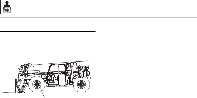
Before ordering parts or initiating service inquiries, make note of the machine serial number. The machine serial number plate (1) is located as indicated in the figure.
MY1000
1
Note: The replacement of any part on this machine with any other than JLG authorized replacement parts can adversely affect the performance, durability, or safety of the machine, and will void the warranty. JLG disclaims liability for any claims or damages, whether regarding property damage, personal injury or death arising out of the use of unauthorized replacement parts.
A warranty registration form must be filled out by the JLG distributor, signed by the purchaser and returned to JLG when the machine is sold and/or put into use.
Registration activates the warranty period and helps to assure that warranty claims are promptly processed. To guarantee full warranty service, verify that the distributor has returned the business reply card of the warranty registration form to JLG.
2.2
G10-55A & G12-55A AccuPlace

55A-G10 |
|
|
|
|
|
|
|
|
|
|
|
|
|
|
|
|
|
1.2.2 |
2.2 |
|
|
|
|
|
|
|
VALUES FOR ZINC PLATED / YELLOW CHROMATE FASTENERS ONLY |
|
UNPLATED CAP SCREWS |
|
|
|
|||||||||||||
AccuPlace55A-G12& |
|
|
|
|
|
|
TORQUES |
|
|
|||||||||||||
|
|
|
|
|
|
|
|
|
|
|
|
|
|
|
|
|
FastenerASTM |
|
||||
40 |
|
0.00604 |
380 |
8 |
6 |
|
— |
— |
540 |
12 |
9 |
— |
— |
— |
— |
— |
|
|
||||
|
|
|
|
|
|
SAE GRADE 5 BOLTS & |
|
SAE GRADE 8 BOLTS & GRADE 8 NUTS |
UNBRAKO 1960 SERIES |
|
|
|
|
|||||||||
|
|
|
|
|
|
GRADE 2 NUTS |
|
|
& SOCKET HEAD CAP SCREWS |
SOCKET HEAD |
|
|
|
|
||||||||
|
|
|
|
|
|
|
|
|
|
|
|
|
|
|
|
|
|
|
|
|
|
|
|
|
|
BOLT |
TENSILE |
CLAMP |
|
TORQUE |
|
CLAMP |
|
TORQUE |
|
CLAMP |
TORQUE |
|
|
|
|
||||
|
|
THDS. |
DRY OR |
|
|
LOCTITE |
LOCTITE |
DRY OR |
|
LOCTITE |
LOCTITE |
WITHOUT |
WITH |
|
|
|
|
|||||
|
SIZE |
PER |
DIA. |
STRESS |
LOAD |
LOCTITE |
LUB |
|
242 OR |
LOAD |
LOCTITE |
LUB |
242 OR |
LOAD |
LOC-WEL |
LOC-WEL |
|
|
|
|
||
|
AREA |
|
262 |
262 |
|
|
|
|
||||||||||||||
|
|
INCH |
|
|
263 |
|
|
271 |
|
263 |
|
271 |
|
PATCH |
PATCH |
|
|
|
|
|||
|
|
|
|
|
|
|
|
|
|
|
|
|
|
|
|
|||||||
|
|
|
IN |
SQ. IN. |
LB. |
IN-LB |
IN-LB |
|
IN-LB |
IN-LB |
LB. |
IN-LB. |
IN-LB |
IN-LB |
IN-LB |
LB. |
IN-LB |
IN-LB |
|
|
|
|
|
4 |
|
0.1120 |
|
|
|
|
|
|
|
|
|
|
|
|
|
|
|
|
|
|
|
|
48 |
0.00661 |
420 |
9 |
7 |
|
— |
— |
600 |
13 |
10 |
— |
— |
— |
— |
— |
Torque |
|
|
|
||
|
|
|
|
|
|
|
||||||||||||||||
|
8 |
32 |
0.1640 |
0.00909 |
580 |
16 |
12 |
|
— |
— |
820 |
23 |
17 |
— |
— |
— |
— |
— |
|
|
|
|
|
6 |
40 |
0.1380 |
0.01015 |
610 |
18 |
13 |
|
— |
— |
920 |
25 |
19 |
— |
— |
— |
— |
— |
|
|
|
|
|
|
32 |
|
0.01400 |
900 |
30 |
22 |
|
— |
— |
1260 |
41 |
31 |
— |
— |
— |
— |
— |
|
|
|
|
|
|
36 |
|
0.01474 |
940 |
31 |
23 |
|
— |
— |
1320 |
43 |
32 |
— |
— |
— |
— |
— |
Chart |
|
|
|
|
|
20 |
|
0.0318 |
2020 |
96 |
75 |
|
— |
105 |
2860 |
144 |
108 |
— |
160 |
3180 |
160 |
168 |
|
|
|
|
|
10 |
24 |
0.1900 |
0.01750 |
1120 |
43 |
32 |
|
— |
— |
1580 |
60 |
45 |
— |
— |
— |
— |
— |
|
|
|
|
|
32 |
0.02000 |
1285 |
49 |
36 |
|
— |
— |
1800 |
68 |
51 |
— |
— |
— |
— |
— |
|
|
|
|
||
|
|
|
|
|
|
|
|
|||||||||||||||
|
1/4 |
|
0.2500 |
|
|
|
|
|
|
|
|
|
|
|
|
|
|
|
(English) |
|
|
|
|
28 |
0.0364 |
2320 |
120 |
86 |
|
— |
135 |
3280 |
168 |
120 |
— |
185 |
3640 |
168 |
178 |
|
|
|
|||
|
|
|
|
|
|
|
||||||||||||||||
|
|
|
IN |
SQ. IN. |
LB. |
FT-LB |
FT-LB |
|
FT-LB |
FT-LB |
LB. |
FT-LB |
FT-LB |
FT-LB |
FT-LB |
LB. |
FT-LB |
FT-LB |
|
|
|
|
|
|
|
|
|
|
|
|
|||||||||||||||
|
5/16 |
18 |
0.3125 |
0.0524 |
3340 |
17 |
13 |
|
16 |
19 |
4720 |
25 |
18 |
22 |
30 |
5240 |
25 |
28 |
|
|
|
|
|
24 |
0.0580 |
3700 |
19 |
14 |
|
17 |
21 |
5220 |
25 |
20 |
25 |
30 |
5800 |
27 |
30 |
|
|
|
|
||
|
|
|
|
|
|
|
|
|||||||||||||||
|
3/8 |
16 |
0.3750 |
0.0775 |
4940 |
30 |
23 |
|
28 |
35 |
7000 |
45 |
35 |
40 |
50 |
7750 |
45 |
50 |
|
|
|
|
|
24 |
0.0878 |
5600 |
35 |
25 |
|
32 |
40 |
7900 |
50 |
35 |
45 |
55 |
8780 |
50 |
55 |
|
|
|
|
||
|
|
|
|
|
|
|
|
|||||||||||||||
|
7/16 |
14 |
0.4375 |
0.1063 |
6800 |
50 |
35 |
|
45 |
55 |
9550 |
70 |
55 |
63 |
80 |
10630 |
70 |
77 |
|
|
|
General |
|
20 |
0.1187 |
7550 |
55 |
40 |
|
50 |
60 |
10700 |
80 |
60 |
70 |
90 |
11870 |
75 |
82 |
|
|
|
|||
|
|
|
|
|
|
|
||||||||||||||||
|
|
|
|
|
|
|
|
|||||||||||||||
|
1/2 |
13 |
0.5000 |
0.1419 |
9050 |
75 |
55 |
|
68 |
85 |
12750 |
110 |
80 |
96 |
120 |
14190 |
110 |
120 |
|
|
|
|
|
20 |
0.1599 |
10700 |
90 |
65 |
|
80 |
100 |
14400 |
120 |
90 |
108 |
130 |
15990 |
115 |
127 |
|
|
|
|
||
|
|
|
|
|
|
|
|
|||||||||||||||
|
9/16 |
12 |
0.5625 |
0.1820 |
11600 |
110 |
80 |
|
98 |
120 |
16400 |
150 |
110 |
139 |
165 |
18200 |
155 |
170 |
|
|
|
|
|
18 |
0.2030 |
12950 |
120 |
90 |
|
109 |
135 |
18250 |
170 |
130 |
154 |
190 |
20300 |
165 |
182 |
|
|
|
Information |
||
|
|
|
|
|
|
|
||||||||||||||||
|
5/8 |
11 |
0.6250 |
0.2260 |
14400 |
150 |
110 |
|
135 |
165 |
20350 |
220 |
170 |
180 |
240 |
22600 |
210 |
231 |
|
|
|
|
|
|
|
|
|
|
|||||||||||||||||
|
18 |
0.2560 |
16300 |
170 |
130 |
|
153 |
190 |
23000 |
240 |
180 |
204 |
265 |
25600 |
220 |
242 |
|
|
|
|
||
|
|
|
|
|
|
|
|
|||||||||||||||
|
3/4 |
10 |
0.7500 |
0.3340 |
21300 |
260 |
200 |
|
240 |
285 |
30100 |
380 |
280 |
301 |
420 |
33400 |
365 |
400 |
|
|
|
|
|
16 |
0.3730 |
23800 |
300 |
220 |
|
268 |
330 |
33600 |
420 |
320 |
336 |
465 |
37300 |
400 |
440 |
|
|
|
|
||
|
|
|
|
|
|
|
|
|||||||||||||||
|
7/8 |
9 |
0.8750 |
0.4620 |
29400 |
430 |
320 |
|
386 |
475 |
41600 |
600 |
460 |
485 |
660 |
46200 |
585 |
645 |
|
|
|
|
|
14 |
0.5090 |
32400 |
470 |
350 |
|
425 |
520 |
45800 |
660 |
500 |
534 |
725 |
50900 |
635 |
700 |
|
|
|
|
||
|
|
|
|
|
|
|
|
|||||||||||||||
|
1 |
8 |
1.0000 |
0.6060 |
38600 |
640 |
480 |
|
579 |
675 |
51500 |
900 |
680 |
687 |
990 |
60600 |
865 |
950 |
|
|
|
and |
|
12 |
0.6630 |
42200 |
700 |
530 |
|
633 |
735 |
59700 |
1000 |
740 |
796 |
1100 |
66300 |
915 |
1000 |
|
|
|
|||
|
|
|
|
|
|
|
||||||||||||||||
|
|
|
|
|
|
|
|
|||||||||||||||
|
1-1/8 |
7 |
1.1250 |
0.7630 |
42300 |
800 |
600 |
|
714 |
840 |
68700 |
1280 |
960 |
1030 |
1400 |
76300 |
1240 |
1365 |
|
|
|
|
|
12 |
0.8560 |
47500 |
880 |
660 |
|
802 |
925 |
77000 |
1440 |
1080 |
1155 |
1575 |
85600 |
1380 |
1520 |
|
|
|
Specifications |
||
|
|
|
|
|
|
|
||||||||||||||||
|
Note: |
These torque values |
do not apply to cadmium plated |
fasteners. |
|
1009 |
1175 |
87200 |
1820 |
1360 |
1453 |
2000 |
96900 |
1750 |
1925 |
|
|
|
||||
|
1-1/4 |
7 |
1.2500 |
0.9690 |
53800 |
1120 |
840 |
|
|
|
|
|
||||||||||
|
|
12 |
|
1.0730 |
59600 |
1240 |
920 |
|
1118 |
1300 |
96600 |
2000 |
1500 |
1610 |
2200 |
107300 |
1880 |
2070 |
|
|
|
|
|
1-3/8 |
6 |
1.3750 |
1.1550 |
64100 |
1460 |
1100 |
|
1322 |
1525 |
104000 |
2380 |
1780 |
1907 |
2625 |
115500 |
2320 |
2550 |
|
|
|
|
|
|
12 |
|
1.3150 |
73000 |
1680 |
1260 |
|
1506 |
1750 |
118100 |
2720 |
2040 |
2165 |
3000 |
131500 |
2440 |
2685 |
|
|
|
|
|
1-1/2 |
6 |
1.5000 |
1.4050 |
78000 |
1940 |
1460 |
|
1755 |
2025 |
126500 |
3160 |
2360 |
2530 |
3475 |
140500 |
3040 |
3345 |
|
|
|
|
|
12 |
1.5800 |
87700 |
2200 |
1640 |
|
1974 |
2300 |
142200 |
3560 |
2660 |
2844 |
3925 |
158000 |
3270 |
3600 |
|
|
|
|
||
|
|
|
|
|
|
|
|
|||||||||||||||
3.2 |
|
|
|
|
|
|
|
|
|
|
|
|
|
|
|
|
|
|
|
|
|
|
|
|
|
|
|
|
|
|
|
|
|
|
|
|
|
|
|
|
|
|
|
|
|
|
|
|
|
|
|
|
|
|
|
|
|
|
|
|
|
|
|
|
|
|
|
|

4.2 |
|
|
|
|
|
|
|
|
|
|
|
|
|
|
|
|
|
|
|
2.2 |
|
|
|
|
|
|
|
|
|
|
|
|
|
|
|
|
|
|
|
|
|
|
2. |
|
|
|
|
|
|
|
|
|
|
VALUES FOR ZINC PLATED / YELLOW CHROMATE FASTENERS ONLY |
|
|
UNPLATED CAP SCREWS |
|
|
|||||||||
|
|
|
|
|
|
|
|
|
|
|
|
|
||||||||||
|
|
|
|
|
|
|
SAE GRADE 5 BOLTS & |
|
SAE GRADE 8 BOLTS & GRADE 8 NUTS |
UNBRAKO 1960 SERIES |
|
|
|
|||||||||
|
|
|
|
|
|
|
|
|
|
|
||||||||||||
|
|
|
|
|
|
|
GRADE 2 NUTS |
|
|
& SOCKET HEAD CAP SCREWS |
SOCKET HEAD |
(Metric)ChartTorqueFastenerASTM |
|
SpecificationsandInformationGeneral |
||||||||
|
|
|
|
|
TENSILE |
|
|
TORQUE |
|
|
|
TORQUE |
|
|
TORQUE |
|
||||||
|
|
|
THDS. |
BOLT |
CLAMP |
DRY OR |
|
|
|
LOCTITE |
CLAMP |
DRY OR |
|
|
LOCTITE |
CLAMP |
WITHOUT |
WITH |
|
|||
|
|
|
STRESS |
|
|
LOCTITE |
|
LOCTITE |
|
|||||||||||||
|
|
SIZE |
PER |
DIA. |
LOAD |
LOCTITE |
LUB |
|
242 OR |
LOAD |
LOCTITE |
LUB |
242 OR |
LOAD |
LOC-WEL |
LOC-WEL |
|
|||||
|
|
AREA |
|
262 |
262 |
|
||||||||||||||||
|
|
|
INCH |
|
|
263 |
|
|
271 |
|
263 |
|
271 |
|
PATCH |
PATCH |
|
|||||
|
|
|
|
|
|
|
|
|
|
|
|
|
|
|||||||||
|
|
|
|
IN |
SQ. IN. |
LB. |
N, m |
N, m |
|
N, m |
N, m |
LB. |
N, m |
N, m |
N, m |
N, m |
LB. |
N, m |
N, m |
|
|
|
|
|
4 |
40 |
0.1120 |
0.00604 |
380 |
.8 |
.8 |
|
— |
— |
540 |
1.4 |
1.0 |
— |
— |
— |
— |
— |
|
|
|
|
|
48 |
0.00661 |
420 |
1.0 |
.8 |
|
— |
— |
600 |
1.5 |
1.0 |
— |
— |
— |
— |
— |
|
|
|
||
|
|
|
|
|
|
|
|
|||||||||||||||
|
|
6 |
32 |
0.1380 |
0.00909 |
580 |
1.8 |
1.4 |
|
— |
— |
820 |
2.6 |
2.0 |
— |
— |
— |
— |
— |
|
|
|
|
|
40 |
0.01015 |
610 |
2.0 |
1.6 |
|
— |
— |
920 |
2.8 |
2.2 |
— |
— |
— |
— |
— |
|
|
|
||
|
|
|
|
|
|
|
|
|||||||||||||||
|
|
8 |
32 |
0.1640 |
0.01400 |
900 |
3.4 |
2.4 |
|
— |
— |
1260 |
4.6 |
3.4 |
— |
— |
— |
— |
— |
|
|
|
|
|
36 |
0.01474 |
940 |
3.4 |
2.6 |
|
— |
— |
1320 |
5 |
3.6 |
— |
— |
— |
— |
— |
|
|
|
||
|
|
|
|
|
|
|
|
|||||||||||||||
|
|
10 |
24 |
0.1900 |
0.01750 |
1120 |
5 |
3.6 |
|
— |
— |
1580 |
7 |
5 |
— |
— |
— |
— |
— |
|
|
|
|
|
32 |
0.02000 |
1285 |
6 |
4 |
|
— |
— |
1800 |
8 |
6 |
— |
— |
— |
— |
— |
|
|
|
||
|
|
|
|
|
|
|
|
|||||||||||||||
|
|
1/4 |
20 |
0.2500 |
0.0318 |
2020 |
11 |
8 |
|
— |
12 |
2860 |
16 |
12 |
— |
18 |
3180 |
18 |
19 |
|
|
|
|
|
28 |
0.0364 |
2320 |
14 |
10 |
|
— |
15 |
3280 |
19 |
14 |
— |
21 |
3640 |
19 |
20 |
|
|
|
||
|
|
|
|
|
|
|
|
|||||||||||||||
|
|
|
|
IN |
SQ. IN. |
LB. |
N, m |
N, m |
|
N, m |
N, m |
LB. |
N, m |
N, m |
N, m |
N, m |
LB. |
N, m |
N, m |
|
|
|
|
|
5/16 |
18 |
0.3125 |
0.0524 |
3340 |
23 |
18 |
|
22 |
26 |
4720 |
34 |
24 |
30 |
41 |
5240 |
34 |
38 |
|
|
|
|
|
24 |
0.0580 |
3700 |
26 |
19 |
|
23 |
28 |
5220 |
34 |
27 |
34 |
41 |
5800 |
37 |
41 |
|
|
|
||
|
|
|
|
|
|
|
|
|||||||||||||||
|
|
3/8 |
16 |
0.3750 |
0.0775 |
4940 |
41 |
31 |
|
38 |
47 |
7000 |
61 |
47 |
54 |
68 |
7750 |
61 |
68 |
|
|
|
|
|
24 |
0.0878 |
5600 |
47 |
34 |
|
43 |
54 |
7900 |
68 |
47 |
61 |
75 |
8780 |
68 |
75 |
|
|
|
||
|
|
|
|
|
|
|
|
|||||||||||||||
|
|
7/16 |
14 |
0.4375 |
0.1063 |
6800 |
68 |
47 |
|
61 |
75 |
9550 |
95 |
75 |
85 |
108 |
10630 |
95 |
104 |
|
|
|
|
|
20 |
0.1187 |
7550 |
75 |
54 |
|
68 |
81 |
10700 |
108 |
81 |
95 |
122 |
11870 |
102 |
111 |
|
|
|
||
|
|
|
|
|
|
|
|
|||||||||||||||
|
|
1/2 |
13 |
0.5000 |
0.1419 |
9050 |
102 |
75 |
|
92 |
115 |
12750 |
149 |
108 |
130 |
163 |
14190 |
149 |
163 |
|
|
|
|
|
20 |
0.1599 |
10700 |
122 |
88 |
|
108 |
136 |
14400 |
163 |
122 |
146 |
183 |
15990 |
156 |
172 |
|
|
|
||
|
|
|
|
|
|
|
|
|||||||||||||||
|
|
9/16 |
12 |
0.5625 |
0.1820 |
11600 |
149 |
108 |
|
133 |
163 |
16400 |
203 |
149 |
188 |
224 |
18200 |
210 |
230 |
|
|
|
|
|
18 |
0.2030 |
12950 |
163 |
122 |
|
148 |
183 |
18250 |
230 |
176 |
209 |
258 |
20300 |
224 |
247 |
|
|
|
||
|
|
|
|
|
|
|
|
|||||||||||||||
|
|
5/8 |
11 |
0.6250 |
0.2260 |
14400 |
203 |
149 |
|
183 |
224 |
20350 |
298 |
230 |
244 |
325 |
22600 |
285 |
313 |
|
|
|
|
|
18 |
0.2560 |
16300 |
230 |
176 |
|
207 |
258 |
23000 |
325 |
244 |
277 |
359 |
25600 |
298 |
328 |
|
|
|
||
|
|
|
|
|
|
|
|
|||||||||||||||
|
|
3/4 |
10 |
0.7500 |
0.3340 |
21300 |
353 |
271 |
|
325 |
386 |
30100 |
515 |
380 |
408 |
569 |
33400 |
495 |
542 |
|
|
|
|
|
16 |
0.3730 |
23800 |
407 |
298 |
|
363 |
447 |
33600 |
569 |
434 |
456 |
630 |
37300 |
542 |
597 |
|
|
|
||
|
|
|
|
|
|
|
|
|||||||||||||||
|
|
7/8 |
9 |
0.8750 |
0.4620 |
29400 |
583 |
434 |
|
523 |
644 |
41600 |
813 |
624 |
658 |
895 |
46200 |
793 |
874 |
|
|
|
|
|
14 |
0.5090 |
32400 |
637 |
475 |
|
576 |
705 |
45800 |
895 |
678 |
724 |
983 |
50900 |
861 |
949 |
|
|
|
||
|
|
|
|
|
|
|
|
|||||||||||||||
|
|
1 |
8 |
1.0000 |
0.6060 |
38600 |
868 |
651 |
|
785 |
915 |
51500 |
1220 |
922 |
931 |
1342 |
60600 |
1173 |
1288 |
|
|
|
|
|
12 |
0.6630 |
42200 |
949 |
719 |
|
858 |
997 |
59700 |
1356 |
1003 |
1079 |
1491 |
66300 |
1241 |
1356 |
|
|
|
||
|
|
|
|
|
|
|
|
|||||||||||||||
|
|
1-1/8 |
7 |
1.1250 |
0.7630 |
42300 |
1085 |
813 |
|
968 |
1139 |
68700 |
1735 |
1302 |
1396 |
1898 |
76300 |
1681 |
1851 |
|
|
|
|
|
12 |
0.8560 |
47500 |
1193 |
895 |
|
1087 |
1254 |
77000 |
1952 |
1464 |
1566 |
2135 |
85600 |
1871 |
2061 |
|
|
|
||
|
|
|
|
|
|
|
|
|||||||||||||||
|
|
1-1/4 |
7 |
1.2500 |
0.9690 |
53800 |
1518 |
1139 |
|
1368 |
1593 |
87200 |
2468 |
1844 |
1970 |
2712 |
96900 |
2373 |
2610 |
|
|
|
|
|
12 |
1.0730 |
59600 |
1681 |
1247 |
|
1516 |
1763 |
96600 |
2712 |
2034 |
2183 |
2983 |
107300 |
2549 |
2807 |
|
|
|
||
|
|
|
|
|
|
|
|
|||||||||||||||
-G10 |
|
1-3/8 |
6 |
1.3750 |
1.1550 |
64100 |
1979 |
1491 |
|
1792 |
2068 |
104000 |
3227 |
2413 |
2586 |
3559 |
115500 |
3145 |
3457 |
|
|
|
12 |
1.3150 |
73000 |
2278 |
1708 |
|
2042 |
2373 |
118100 |
3688 |
2766 |
2935 |
4067 |
131500 |
3308 |
3640 |
|
|
|
||||
|
|
|
|
|
|
|||||||||||||||||
55A |
1-1/2 |
6 |
1.5000 |
1.4050 |
78000 |
2630 |
1979 |
|
2379 |
2745 |
126500 |
4284 |
3200 |
3430 |
4711 |
140500 |
4122 |
4535 |
|
|
|
|
12 |
1.5800 |
87700 |
2983 |
2224 |
|
2676 |
3118 |
142200 |
4827 |
3606 |
3856 |
5322 |
158000 |
4433 |
4881 |
|
|
|
||||
& |
|
|
|
|
|
|
|
|||||||||||||||
|
|
|
|
|
|
|
|
|
|
|
|
|
|
|
|
|
|
|
|
|
|
|
AccuPlace 55A-G12 |
|
Note: These torque values do not apply to cadmium plated fasteners. |
|
|
|
|
|
|
|
|
|
|
|
|
|
|||||||
|
|
|
|
|
|
|
|
|
|
|
|
|
|
|
|
|
|
|
|
|
|
|
|
|
|
|
|
|
|
|
|
|
|
|
|
|
|
|
|
|
|
|
|
|
|
General Information and Specifications
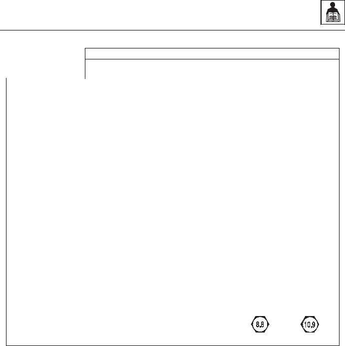
2.2.3Metric Fastener Torque Chart
VALUES FOR ZINC PLATED / YELLOW CHROMATE FASTENERS ONLY
|
|
|
|
CLASS 8.8 METRIC BOLTS & |
|
|
CLASS 10.9 METRIC BOLTS & |
|
|||||
|
|
|
|
CLASS 8 METRIC NUTS |
|
|
CLASS 10 METRIC NUTS |
|
|||||
|
|
|
|
|
|
|
|
|
|
|
|
|
|
|
|
TENSILE |
|
|
TORQUE |
|
|
|
TORQUE |
|
|||
|
|
CLAMP |
DRY OR |
|
|
LOCTITE |
CLAMP |
DRY OR |
|
|
|
LOCTITE |
|
|
|
STRESS |
|
LOCTITE |
|
LOCTITE |
|
||||||
SIZE |
PITCH |
LOAD |
|
LOAD |
|
|
|||||||
AREA |
LOCTITE |
LUB |
242 OR |
LOCTITE |
LUB |
|
242 OR |
||||||
262 |
262 |
|
|||||||||||
|
|
|
263 |
|
271 |
|
263 |
|
|
271 |
|||
|
|
|
|
|
|
|
|
|
|
||||
|
|
sq. mm |
KN |
N, m |
N, m |
N, m |
N, m |
KN |
N, m |
N, m |
N, m |
|
N, m |
3 |
.5 |
5.03 |
2.19 |
1.3 |
1.0 |
1.2 |
1.4 |
3.13 |
1.9 |
1.4 |
1.5 |
|
2.1 |
|
|
|
|
|
|
|
|
|
|
|
|
|
|
3.5 |
.6 |
6.78 |
2.95 |
2.1 |
1.6 |
1.9 |
2.3 |
4.22 |
3.0 |
2.2 |
2.4 |
|
3.3 |
|
|
|
|
|
|
|
|
|
|
|
|
|
|
4 |
.7 |
8.78 |
3.82 |
3.1 |
2.3 |
2.8 |
3.4 |
5.47 |
4.4 |
3.3 |
3.5 |
|
4.8 |
|
|
|
|
|
|
|
|
|
|
|
|
|
|
5 |
.8 |
14.2 |
6.18 |
6.2 |
4.6 |
5.6 |
6.8 |
8.85 |
8.9 |
6.6 |
7.1 |
|
9.7 |
|
|
|
|
|
|
|
|
|
|
|
|
|
|
6 |
1 |
20.1 |
8.74 |
11 |
7.9 |
9.4 |
12 |
12.5 |
15 |
11 |
12 |
|
17 |
|
|
|
|
|
|
|
|
|
|
|
|
|
|
7 |
1 |
28.9 |
12.6 |
18 |
13 |
16 |
19 |
18 |
25 |
19 |
20 |
|
28 |
|
|
|
|
|
|
|
|
|
|
|
|
|
|
8 |
1.25 |
36.6 |
15.9 |
25 |
19 |
23 |
28 |
22.8 |
37 |
27 |
29 |
|
40 |
|
|
|
|
|
|
|
|
|
|
|
|
|
|
10 |
1.5 |
58.0 |
25.2 |
50 |
38 |
45 |
55 |
36.1 |
72 |
54 |
58 |
|
79 |
|
|
|
|
|
|
|
|
|
|
|
|
|
|
12 |
1.75 |
84.3 |
36.7 |
88 |
66 |
79 |
97 |
52.5 |
126 |
95 |
101 |
|
139 |
|
|
|
|
|
|
|
|
|
|
|
|
|
|
14 |
2 |
115 |
50.0 |
140 |
105 |
126 |
154 |
71.6 |
200 |
150 |
160 |
|
220 |
|
|
|
|
|
|
|
|
|
|
|
|
|
|
16 |
2 |
157 |
68.3 |
219 |
164 |
197 |
241 |
97.8 |
313 |
235 |
250 |
|
344 |
|
|
|
|
|
|
|
|
|
|
|
|
|
|
18 |
2.5 |
192 |
83.5 |
301 |
226 |
271 |
331 |
119.5 |
430 |
323 |
344 |
|
473 |
|
|
|
|
|
|
|
|
|
|
|
|
|
|
20 |
2.5 |
245 |
106.5 |
426 |
320 |
383 |
469 |
152.5 |
610 |
458 |
488 |
|
671 |
|
|
|
|
|
|
|
|
|
|
|
|
|
|
22 |
2.5 |
303 |
132.0 |
581 |
436 |
523 |
639 |
189.0 |
832 |
624 |
665 |
|
915 |
|
|
|
|
|
|
|
|
|
|
|
|
|
|
24 |
3 |
353 |
153.5 |
737 |
553 |
663 |
811 |
220.0 |
1060 |
792 |
845 |
|
1170 |
|
|
|
|
|
|
|
|
|
|
|
|
|
|
27 |
3 |
459 |
199.5 |
1080 |
810 |
970 |
1130 |
286.0 |
1540 |
1160 |
1240 |
|
1690 |
|
|
|
|
|
|
|
|
|
|
|
|
|
|
30 |
3.5 |
561 |
244.0 |
1460 |
1100 |
1320 |
1530 |
349.5 |
2100 |
1570 |
1680 |
|
2310 |
|
|
|
|
|
|
|
|
|
|
|
|
|
|
33 |
3.5 |
694 |
302.0 |
1990 |
1490 |
1790 |
2090 |
432.5 |
2600 |
2140 |
2280 |
|
2860 |
|
|
|
|
|
|
|
|
|
|
|
|
|
|
36 |
4 |
817 |
355.0 |
2560 |
1920 |
2300 |
2690 |
509.0 |
3660 |
2750 |
2930 |
|
4020 |
|
|
|
|
|
|
|
|
|
|
|
|
|
|
42 |
4.5 |
1120 |
487.0 |
4090 |
3070 |
3680 |
4290 |
698.0 |
5860 |
4400 |
4690 |
|
6440 |
|
|
|
|
|
|
|
|
|
|
|
|
|
|
Note: These torque values do not apply to cadmium plated fasteners.
METRIC CLASS 8.8 METRIC CLASS 10.9
G10-55A & G12-55A AccuPlace |
2.5 |

General Information and Specifications
2.3SPECIFICATIONS
2.3.1Travel Speeds
|
G10-55A |
G12-55A |
|
|
|
First Gear |
3.4 mph (5,4 km/h) |
3.5 mph (5,6 km/h) |
|
|
|
Second Gear |
6.1 mph (9,8 km/h) |
6.3 mph (10,1 km/h) |
|
|
|
Third Gear |
13.8 mph (22,2 km/h) |
14.1 mph (22,7 km/h) |
|
|
|
Fourth Gear |
20.0 mph (32,2 km/h) |
20.4 mph (32,8 km/h) |
|
|
|
2.3.2Electrical System
Battery:
Type, Rating |
12 BCI, Negative (-) Ground, Maintenance Free |
|
|
Quantity |
1 |
|
|
Reserve Capacity |
1,000 Cold Cranking Amps @ 0° F (-18° C) |
|
|
Group/Series |
Group 31 |
|
|
Alternator |
12V, 95 Amps |
|
|
2.3.3Engine Performance Specifications
Description |
G10-55A |
G12-55A |
|
|
|
Engine Make/Model |
Perkins 1104D - 125HP |
Perkins 1104D - 142 HP |
|
|
|
Displacement |
269 in³ (4,4 liters) |
269 in³ (4,4 liters) |
|
|
|
Low Idle |
1000 rpm |
900 rpm |
|
|
|
High Idle |
2,400 to 2,650 rpm |
2,400 to 2,650 rpm |
|
|
|
Horsepower |
125 HP (93 kW) @ 2400 rpm |
142 HP (104 kW) @ 2400 rpm |
|
|
|
Peak Torque |
Not Available at Publication |
410 lb-ft (556 Nm) @ 1400 rpm |
|
|
|
Fuel Delivery |
Fuel Injection |
Fuel Injection |
|
|
|
Air Cleaner |
Dry Type, Replaceable Primary and |
Dry Type, Replaceable Primary and |
|
Safety Elements |
Safety Elements |
|
|
|
2.6 |
G10-55A & G12-55A AccuPlace |

General Information and Specifications
2.3.4Tires
Note: Standard wheel lug nut torque is 350-400 lb-ft (475-542 Nm).
a. G10-55A |
|
|
|
|
|
|
|
|
|
Size |
Tire Type |
Minimum Ply/ |
Fill Type |
Pressure |
|
|
Star Rating |
|
|
|
|
|
|
|
14.00 x 24 |
G-2/L-2 Bias Ply Traction |
12 Ply |
Pneumatic |
65 psi (4,5 bar) |
|
|
|
|
|
|
|
|
approx. 720 lb foam |
|
|
|
|
|
|
14.00 x 24 |
G-3/L-3 Bias Ply Rock |
12 Ply |
Pneumatic |
65 psi (4,5 bar) |
|
|
|
|
|
|
|
|
approx. 720 lb foam |
|
|
|
|
|
|
14.00 x 24 |
G-2/L-2 Radial |
1 Star |
Pneumatic |
70 psi (4,8 bar) |
|
|
|
|
|
|
|
|
approx. 720 lb foam |
|
|
|
|
|
|
14.00 x 24 |
Solid |
N/A |
Solid Rubber |
N/A |
|
|
|
|
|
17.50 x 25 |
G-2/L-2 Bias Ply Traction |
12 Ply |
Pneumatic |
65 psi (4,5 bar) |
|
|
|
|
|
|
|
|
approx. 785 lb foam |
|
|
|
|
|
|
17.50 x 25 |
G-3/L-3 Bias Ply Rock |
12 Ply |
Pneumatic |
65 psi (4,5 bar) |
|
|
|
|
|
|
|
|
approx. 785 lb foam |
|
|
|
|
|
|
17.50 x 25 |
G-2/L-2 Radial |
1 Star |
Pneumatic |
70 psi (4,8 bar) |
|
|
|
|
|
|
|
|
approx. 785 lb foam |
|
|
|
|
|
|
b. G12-55A
Size |
Tire Type |
Minimum Ply/ |
Fill Type |
Pressure |
|
|
Star Rating |
|
|
|
|
|
|
|
14.00 x 24 |
Solid |
N/A |
Solid Rubber |
N/A |
|
|
|
|
|
17.50 x 25 |
G-2/L-2 Bias Ply Traction |
12 Ply |
Pneumatic |
65 psi (4,5 bar) |
|
|
|
|
|
|
|
|
approx. 785 lb foam |
|
|
|
|
|
|
17.50 x 25 |
G-3/L-3 Bias Ply Rock |
12 Ply |
Pneumatic |
65 psi (4,5 bar) |
|
|
|
|
|
|
|
|
approx. 785 lb foam |
|
|
|
|
|
|
17.50 x 25 |
G-2/L-2 Radial |
1 Star |
Pneumatic |
70 psi (4,8 bar) |
|
|
|
|
|
|
|
|
approx. 785 lb foam |
|
|
|
|
|
|
G10-55A & G12-55A AccuPlace |
2.7 |

General Information and Specifications
2.4FLUID AND LUBRICANT CAPACITIES
Engine Crankcase Oil
Capacity with Filter Change - Perkins |
7 quarts (6,5 liters) |
|
|
Oil Type |
15W-40 CE |
|
|
Fuel Tank |
|
|
|
Capacity |
38 gallons (144 liters) |
|
|
Type of Fuel |
Low Sulfur Diesel #2 |
|
|
Cooling System |
|
|
|
System Capacity - Perkins |
20.5 quarts (19,4 liters) |
|
|
Overflow Bottle Capacity |
3 quarts (2,8 liters) |
|
|
Type of Fluid |
50/50 ethylene glycol & water |
|
|
Coolant Conditioner (refer engine manual) |
0.5 quarts (0,47 liters) |
|
|
Transmission |
|
|
|
Capacity with Filter Change |
4.23 gallons (16 liters) |
|
|
Type of Fluid |
Mobilfluid® 424 Tractor Hydraulic Fluid (ISO 46) |
Transfer Case |
|
|
|
Capacity |
1.5 quarts (1,4 liters) |
|
|
Type of Fluid |
Mobilfluid® 424 Tractor Hydraulic Fluid (ISO 46) |
Axles |
|
|
|
Differential Housing Capacity |
Front Axle - 15.8 quarts (15 liters) |
|
Rear Axle - 16.9 quarts (16 liters) |
|
|
Wheel End Capacity |
2 quarts (1,9 liters) |
|
|
Type of Fluid |
Mobilfluid® 424 Tractor Hydraulic Fluid (ISO 46) |
Hydraulic System |
|
|
|
System Capacity |
G10-55A - 63 gallons (238 liters) |
|
G12-55A - 65 gallons (246 liters) |
|
|
Reservoir Capacity |
38 gallons (144 liters) |
|
|
Auxiliary Hydraulic Circuit Max Flow |
16 gpm (72,7 lpm) |
|
|
Type of Fluid |
Mobilfluid® 424 Tractor Hydraulic Fluid |
2.8 |
G10-55A & G12-55A AccuPlace |
General Information and Specifications
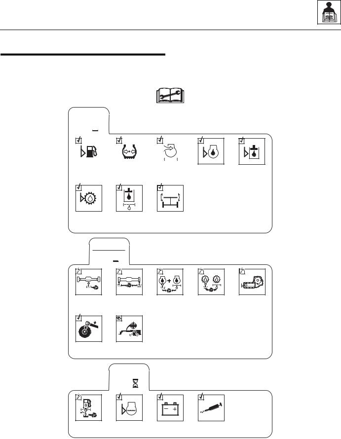
2.5SERVICE AND MAINTENANCE SCHEDULES
2.5.110, 1st 100 & 50 Hour
EVERY
10 
|
|
|
|
|
|
|
|
|
|
|
|
|
|
|
|
|
|
|
|
|
|
|
|
|
|
|
|
|
|
|
|
|
|
|
|
|
|
|
|
|
|
|
|
|
|
|
|
|
|
|
|
|
|
|
|
|
|
|
|
|
|
|
|
|
|
|
|
|
|
|
|
Check Fuel |
|
Check Tire |
|
Air Filter |
|||||||
|
Level |
|
Pressure |
Restriction |
|||||||
|
|
|
|
|
|
|
|
Indicator |
|||
|
|
A |
Check |
Check Hydraulic |
Check Auto- |
Transmission |
Return Filter |
Sway Function |
Oil Level |
Indicator |
|
Check Engine |
Check Hydraulic |
Oil Level |
Oil Level |
1st
100 
Change |
Axle Oil |
LB |
/FT ( |
Nm) |
Check Wheel
Lug Nut
Torque
Change Wheel |
End Oil |
Check Boom |
Chain Tension |
|
EVERY |
|
50 |
Drain Fuel/ |
Check Engine |
Water |
Coolant Level |
Separator |
|
Change Engine |
Oil & Filter |
Check |
Battery |
Change |
Transmission |
Oil & Filter |
Lubrication |
Schedule |
Change |
Transfer |
Case Oil |
MY1731
G10-55A & G12-55A AccuPlace |
2.9 |
General Information and Specifications
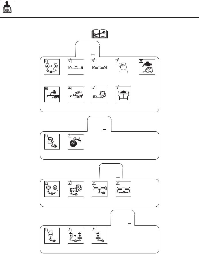
2.5.2250, 500, 1000 & 1500 Hour
Change Engine |
Oil and |
Filter* |
Check Boom |
Chain |
Tension |
EVERY
250 
Check Axle
Oil Level
Check Boom |
Bearing |
Pads |
|
|
|
|
|
|
|
|
|
|
|
|
|
|
|
|
|
|
|
|
|
|
|
|
|
|
|
|
|
|
|
|
|
Check Wheel |
|
Air Filter |
||||
End Oil Levels |
Vacuator |
||||||
|
|
|
|
|
|
Valve |
|
Check Transfer |
Check Rear Axle |
Case Oil Level |
Stabilization |
|
(if equipped) |
Check |
Fan Belt |
Change Fuel |
Filter |
EVERY
500 
LB |
/FT ( |
Nm) |
Check Wheel |
Lug Nut |
Torque |
Change |
Transmission |
Oil & Filter |
Change |
Transfer Case |
Oil |
EVERY
1000 
Change |
Change Wheel |
Axle Oil |
End Oil |
EVERY
1500 
Change |
Change |
Change |
Engine Coolant |
Hydraulic |
Hydraulic Tank |
|
Fluid & Filters |
Breather |
MY0090
Note: Engine oil & filter service interval can be extended. See Engine Manual for details.
2.10 |
G10-55A & G12-55A AccuPlace |

General Information and Specifications
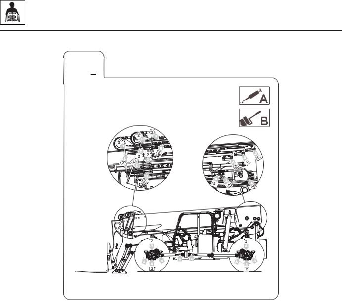
2.6LUBRICATION SCHEDULES
a. 50 Hour
EVERY
50 
OY1630
G10-55A & G12-55A AccuPlace |
2.11 |
General Information and Specifications
b. 250 Hour
EVERY
250 
OW1210
2.12 |
G10-55A & G12-55A AccuPlace |

Section 3
Boom
Contents
PARAGRAPH |
TITLE |
PAGE |
|
3.1 |
Boom System Component Terminology . . . . . . . . . . . . . . . . . . . . . . . . . . . . . . . . |
3.2 |
|
3.2 |
Boom System - Four Section . . . . . . . . . . . . . . . . . . . . . . . . . . . . . . . . . . . . . . . . . |
3.3 |
|
|
3.2.1 |
Boom System Operation . . . . . . . . . . . . . . . . . . . . . . . . . . . . . . . . . . . . . . |
3.3 |
3.3 |
Boom Assembly Maintenance . . . . . . . . . . . . . . . . . . . . . . . . . . . . . . . . . . . . . . . . |
3.3 |
|
|
3.3.1 |
Boom Removal . . . . . . . . . . . . . . . . . . . . . . . . . . . . . . . . . . . . . . . . . . . . . |
3.3 |
|
3.3.2 |
Second, Third & Fourth Boom Section Removal . . . . . . . . . . . . . . . . . . . |
3.4 |
|
3.3.3 |
Third & Fourth Boom Section Removal. . . . . . . . . . . . . . . . . . . . . . . . . . . |
3.4 |
|
3.3.4 |
Fourth Boom Section Removal . . . . . . . . . . . . . . . . . . . . . . . . . . . . . . . . . |
3.5 |
|
3.3.5 |
Fourth Boom Section Installation . . . . . . . . . . . . . . . . . . . . . . . . . . . . . . . |
3.5 |
|
3.3.6 |
Third & Fourth Boom Section Installation . . . . . . . . . . . . . . . . . . . . . . . . . |
3.6 |
|
3.3.7 |
Second Boom Section Installation . . . . . . . . . . . . . . . . . . . . . . . . . . . . . . |
3.7 |
|
3.3.8 |
Boom Installation. . . . . . . . . . . . . . . . . . . . . . . . . . . . . . . . . . . . . . . . . . . . |
3.8 |
3.4 |
Boom Extend and Retract Chains . . . . . . . . . . . . . . . . . . . . . . . . . . . . . . . . . . . . . |
3.9 |
|
|
3.4.1 |
Boom Chain Inspection . . . . . . . . . . . . . . . . . . . . . . . . . . . . . . . . . . . . . . . |
3.9 |
|
3.4.2 |
Inspection Guidelines . . . . . . . . . . . . . . . . . . . . . . . . . . . . . . . . . . . . . . . . |
3.9 |
|
3.4.3 |
Expose Chains for Inspection . . . . . . . . . . . . . . . . . . . . . . . . . . . . . . . . . . |
3.11 |
|
3.4.4 |
Chain Lubrication . . . . . . . . . . . . . . . . . . . . . . . . . . . . . . . . . . . . . . . . . . . |
3.12 |
|
3.4.5 |
Retract Chain Removal . . . . . . . . . . . . . . . . . . . . . . . . . . . . . . . . . . . . . . . |
3.12 |
|
3.4.6 |
Retract Chain Installation . . . . . . . . . . . . . . . . . . . . . . . . . . . . . . . . . . . . . |
3.13 |
|
3.4.7 |
Extend Chain Removal . . . . . . . . . . . . . . . . . . . . . . . . . . . . . . . . . . . . . . . |
3.13 |
|
3.4.8 |
Extend Chain Installation . . . . . . . . . . . . . . . . . . . . . . . . . . . . . . . . . . . . . |
3.13 |
3.5 |
Boom Section Separation Adjustment . . . . . . . . . . . . . . . . . . . . . . . . . . . . . . . . . |
3.14 |
|
3.6 |
Hydraulic Sub-Assembly Removal/Installation . . . . . . . . . . . . . . . . . . . . . . . . . . |
3.14 |
|
|
3.6.1 |
Hydraulic Sub-Assembly Removal . . . . . . . . . . . . . . . . . . . . . . . . . . . . . . |
3.14 |
|
3.6.2 |
Assembling the Hydraulic Sub-Assembly . . . . . . . . . . . . . . . . . . . . . . . . . |
3.16 |
|
3.6.3 |
Hydraulic Sub-Assembly Installation. . . . . . . . . . . . . . . . . . . . . . . . . . . . . |
3.16 |
3.7 |
Boom Wear Pads . . . . . . . . . . . . . . . . . . . . . . . . . . . . . . . . . . . . . . . . . . . . . . . . . . . |
3.17 |
|
|
3.7.1 |
Wear Pad Inspection . . . . . . . . . . . . . . . . . . . . . . . . . . . . . . . . . . . . . . . . . |
3.17 |
|
3.7.2 |
Boom Wear Pad Replacement . . . . . . . . . . . . . . . . . . . . . . . . . . . . . . . . . |
3.17 |
|
3.7.3 |
Boom Wear Pad Lubrication . . . . . . . . . . . . . . . . . . . . . . . . . . . . . . . . . . . |
3.17 |
3.8 |
Quick Switch Assembly . . . . . . . . . . . . . . . . . . . . . . . . . . . . . . . . . . . . . . . . . . . . . |
3.18 |
|
|
3.8.1 |
Quick Switch Removal . . . . . . . . . . . . . . . . . . . . . . . . . . . . . . . . . . . . . . . |
3.18 |
|
3.8.2 |
Quick Switch Installation . . . . . . . . . . . . . . . . . . . . . . . . . . . . . . . . . . . . . . |
3.18 |
3.9 |
Forks . . |
. . . . . . . . . . . . . . . . . . . . . . . . . . . . . . . . . . . . . . . . . . . . . . . . . . . . . . . . . . |
3.18 |
3.10 |
Troubleshooting . . . . . . . . . . . . . . . . . . . . . . . . . . . . . . . . . . . . . . . . . . . . . . . . . . . |
3.19 |
|
G10-55A & G12-55A AccuPlace |
3.1 |
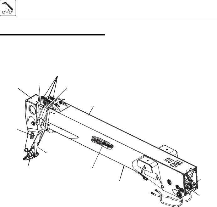
Boom
3.1BOOM SYSTEM COMPONENT TERMINOLOGY
The following illustrations identify the components that are referred to throughout this section.
|
|
EXTEND |
|
|
CHAINS |
|
THIRD BOOM |
SECOND BOOM |
FOURTH BOOM |
SECTION |
|
SECTION |
|
SECTION |
FIRST
BOOM
SECTION
ELECTRICAL
CONNECTION
|
ATTACHMENT |
|
TILT CYLINDER |
ATTACHMENT |
BOOM HYDRAULIC |
QUICK SWITCH |
ASSEMBLY |
|
(Inside Boom) |
EXTEND/RETRACT
CYLINDER
(Underside Of Boom)
3.2
RETRACT
CHAINS
 HOSE
HOSE
SHEAVES
MAP0500
G10-55A & G12-55A AccuPlace

Boom
3.2BOOM SYSTEM - FOUR SECTION
3.2.1Boom System Operation
The four section boom consists of the first, second, third and fourth assemblies with double third and fourth section extend chains, a double third section retract chain and a single fourth section retract chain.
As the extend/retract cylinder, which is anchored at the front of the second boom section, and the rear of the first boom section begins to extend, it forces the second boom section out of the first boom section.
The boom sections are connected by extend and retract chains. These chains are routed around sheaves on the second and third boom sections. As the second section is forced out hydraulically, the third and fourth boom sections are pulled out by the extend chains.
As hydraulic pressure is applied to the retract port on the extend/retract cylinder, the second boom section is pulled back into the first boom section, and the retract chain pulls the third and fourth boom sections back into the second boom section.
This mechanical linkage formed by the chains and supporting hardware, extends and retracts the third and fourth boom sections at the same rate.
The boom section lifts and lowers via action of the lift/ lower cylinder.
3.3BOOM ASSEMBLY MAINTENANCE
These instructions must be completed in sequence. The second, third and fourth boom sections are removed from the first boom section. The third and fourth boom sections are removed from the second boom section. The fourth boom section is removed from the third boom section.
Before beginning, conduct a visual inspection of the machine and work area, and review the task about to be undertaken. Read, understand and follow these instructions.
3.3.1Boom Removal
1.Remove any attachment from the quick switch assembly.
Note: If replacing the fourth section boom, remove the quick switch from the fourth section. Refer to Section 3.8.1, “Quick Switch Removal.”
2.Park the machine on a hard, level surface, level the machine, fully retract the boom, raise the boom, place the transmission control lever in
(N) NEUTRAL, engage the park brake and shut the engine OFF.
3.Place a Do Not Operate Tag on both the ignition key switch and the steering wheel, stating that the machine should not be operated.
4.Open the engine cover. Allow the system fluids to cool.
5.Remove the battery negative (-) cable from the battery negative (-) terminal.
6.Support the front of the boom by placing a sling behind the boom head.
7.Label, disconnect and cap all hydraulic hoses for the extend/retract and tilt circuits. Cap all fittings and openings to keep dirt & debris from entering the hydraulic system.
8.Support the lift cylinder on the left side of the machine. Remove the lock bolt and rod end pin. Lower the lift cylinder onto the frame rails. Repeat this step for the right side lift cylinder.
9.Lower the boom to a level position and place a suitable support under the boom head. Reposition the slings to each end of the boom.
10.Remove the boom angle sensors from both the left and right side of the boom. Refer to Section 9.11.12, “Boom Angle Sensors.”
11.Remove the bolt securing the boom pivot pin. Pull out the boom pivot pin.
12.Lift the complete boom off machine and set on level ground or supports.
 WARNING
NEVER weld or drill the boom unless approved in writing by JLG. The structural integrity of the boom will be impaired if subjected to any repair involving welding or drilling. Failure to comply can result in death or severe personal injury.
G10-55A & G12-55A AccuPlace |
3.3 |
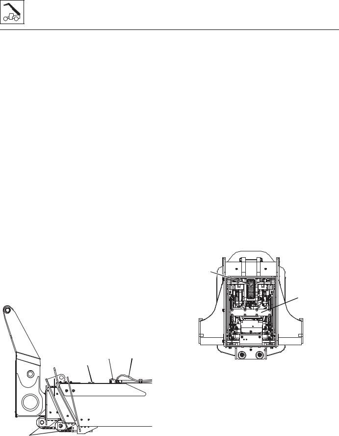
Boom
3.3.2Second, Third & Fourth Boom Section Removal
1.Set the complete boom on level ground and by repositioning the slings, turn boom over on to the top side. Set the complete boom on suitable stands to begin tear down.
Note: With the complete boom setting upside down, the removal and replacing of each boom section, hoses, extend and retract chains and hose carrier are made much easier.
2.Remove the extend/retract cylinder support from the front of the boom.
3.Support the extend/retract cylinder with a suitable sling. Remove the lock bolt and pin from both ends of the cylinder. Remove the cylinder.
4.Unhook the latch on the Boom Length Sensor cable from the third boom section. Refer to Section 9.11.13, “Boom Length Sensor.”
5.At the boom head, attach a sling through the rod end of the tilt cylinder. Remove both hoses from the tilt cylinder. Plug the hose ends and cap the tilt cylinder fittings to prevent dirt and debris from entering the hydraulic system. Remove the pin from the barrel end of the tilt cylinder and remove the cylinder from the boom head.
6.Loosen and remove the bottom rear wear pads and rear side bearing pads from the second boom section. Tag each pad, backing plate, shim and bolts from each location.
7.Release tension from the hoses on the hose take-up weldment (1).
hose ends and tube ends to prevent dirt and debris from entering the hydraulic system.
9.Disconnect the top front chains (3) from the chain clevis on the first and second boom section.
10.Release the chain tension from the front top chains.
11.Remove the front top chain rollers from the second and third boom sections.
12.Remove the chain adjustment block (4) from the first boom section.
13.Remove all wear pads from the front of the first boom section. Tag each pad, backing plate, shim and bolts from each location.
14.Carefully pull the second, third and fourth boom sections together from the first boom section and place on suitable support for further separation.
3.3.3Third & Fourth Boom Section Removal
1.Loosen and remove the bottom rear and side wear pads from the third boom section. Tag each pad, backing plate, shim and bolts from each location.
2.Remove the standard and optional hose sheaves from the rear of the second boom section.
3.Remove the chain and chain clevis (5) from the rear of the second boom section.
5
 6
6
1 2
4
3 |
MAP0660 |
8.Loosen the hydraulic hoses (2) and electrical cables if equipped on the hose take-up weldment. Plug the
MAP0670
4.Remove the hydraulic sub-assembly bracket (6) and hardware from the rear of the third boom section.
5.Pull the hydraulic sub-assembly partially out through the rear of the boom to access the hoses.
6.Loosen and remove the hoses from the rear of the hydraulic sub-assembly.
7.Release the tension on the clevis before proceeding.
8.Loosen and remove the chain adjustment block from the bottom of the boom.
3.4 |
G10-55A & G12-55A AccuPlace |
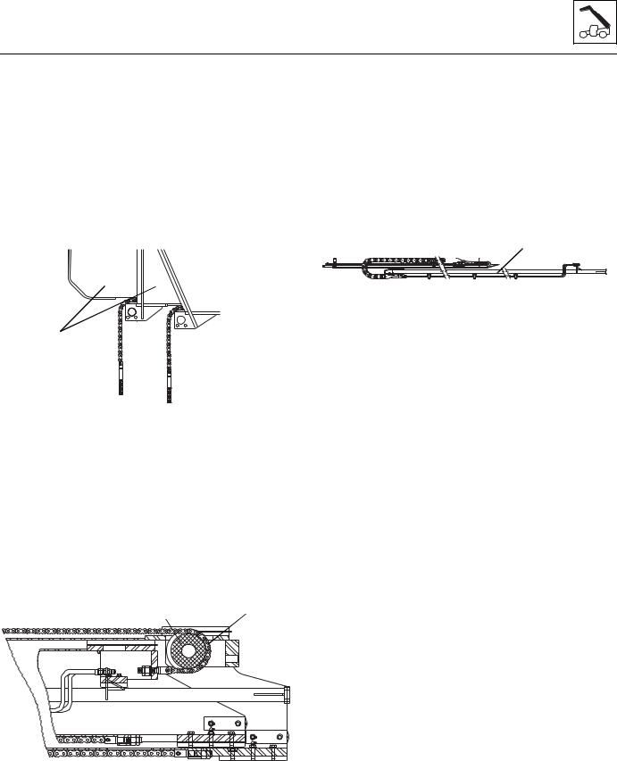
Boom
9.Loosen and remove all the wear pads from the front of the second boom section. Tag each pad, backing plate, shim and bolts from each location.
10.Place a sling around the third boom section, lift and slowly pull the third and fourth boom sections (7) approximately half way out of the second boom section. Lower the third and fourth boom sections onto a suitable support.
11.Relocate the sling or using two slings for better stability, balance the two boom sections and slowly pull them out of the second boom section being careful not to damage any surrounding components.
7
 8
8
MY1690
12.Remove the chain (8) from the second boom section to the third boom section after the boom sections are free from each other.
13.Lower the third and fourth boom sections onto a suitable support.
3.3.4Fourth Boom Section Removal
1.Remove the bottom rear and side bearing pads from the fourth boom section. Tag each pad, backing plate, shim and bolts from each location.
2.Loosen and remove the 3/4 in. chain (9) through the rear of the fourth boom section.
10 |
9 |
MX0380
3.Loosen and remove the retract chain roller (10) at the rear of the third boom section.
G10-55A & G12-55A AccuPlace
4.Loosen and remove the front wear pads and supports from the third boom section. Tag each pad, backing plate, shim and bolts from each location.
5.Carefully pull the fourth boom section out of the third boom section, taking care to protect the chains.
6.Disconnect the chains when the boom sections are free from each other.
7.Place the fourth boom section onto suitable supports.
If the hydraulic sub-assembly (11) is going to be removed:
11
MX0390
8.Remove the guide bracket from the front of the hydraulic sub-assembly.
9.Remove the hardware securing the hydraulic subassembly to the front of the boom.
10.Install a sling on the hydraulic sub-assembly at the rear of the boom. Slowly pull it loose from the bottom bracket located on the bottom plate of the fourth boom section.
11.When the sub-assembly is approximately 25% free of the boom, fasten the two hose carriers together (using nylon tie-wraps or nylon straps) to prevent them from separating.
Note: Do not wrap the hose carrier since it will not prevent the two hydraulic carriers from moving apart sideways.
12.Continue to withdraw the sub-assembly, fastening the hydraulic carriers together as they are removed.
13.When the hydraulic carrier is approximately 75% tied together, pull the assembly free of the boom.
3.3.5Fourth Boom Section Installation
1.Clean and lubricate the inside of the boom sections where the hydraulic sub-assembly rides
(if removed).
2.Using a sling, lift the balanced hydraulic subassembly and slowly insert it into the fourth boom section.
3.As the first tie wrap nears the boom, remove the tie wrap and continue inserting the sub-assembly and removing each tie wrap until the sub-assembly is fully inserted.
3.5
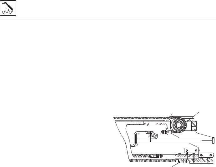
Boom
Note: Be certain the hydraulic sub-assembly locks into place on the pin bracket at the bottom of the fourth boom section.
4.Reconnect the hydraulic hoses and any optional circuits.
5.Install the guide bracket and hardware to secure the hydraulic sub-assembly to the front of the boom.
6.Reinstall the hose take-up compression spring. Torque the jam nut to 100 lb-ft. There should be a 1 in. (25 mm) gap from the back of the jam nut to the end of the threads on the hose take-up weldment.
7.Install the wear pads, backing plates and shims to the top, bottom and sides of the fourth boom section. Do not shim or tighten the bolts at this time.
8.Attach the chain clevis and the keeper plate to the inside rear of the boom.
9.Install the grease fitting extensions for the bottom rear wear pads.
10.Lubricate the extend chain completely. Make sure the chain is inspected and is in good working condition. See Section 3.4.4, “Chain Lubrication.”
11.Attach the chain to the chain clevis.
12.Attach the chain clevis to the top of the fourth boom section.
13.Grease the inside of the third boom section on areas where the fourth boom section wear pads will slide.
14.Using a suitable sling, balance the fourth boom section and carefully slide 3-4 ft (1-1,5 m) into the front of the third boom section. Set the fourth boom section head onto suitable supports and reset sling under the boom head. Carefully slide the fourth boom section into the third boom section. Leave 6-8 in (15-20 cm) of the fourth boom section out to be able to install wear pads on the front of the third boom section.
15.With the boom head still supported, install the top wear pads, washers and bolts in the front of the third boom section. Remove the boom head from supports and install the remaining wear pads inside the third boom section. Do not shim or tighten the bolts at this time.
16.Install the grease fittings for the wear pad and chain roller assembly.
3.3.6Third & Fourth Boom Section Installation
1.Install the top, bottom and side rear wear pads onto the third boom section. Do not shim or tighten the bolts at this time.
3.6
2.Grease the inside of the second boom section on areas where the third section wear pads will slide.
3.Install the grease fittings for the wear pad and chain roller assembly.
4.Install the chain clevis to the rear of the third boom section.
5.Install the chain roller (1) at the bottom rear of the boom.
6.Install the chain roller at the top front of the boom.
7.Lay out and lubricate the retract chain. Make sure the chain has been inspected and meets the adjustment parameters in Section 3.4.1, “Boom Chain Inspection.”
8.Connect the retract chain (2) to the clevis at the rear of the fourth boom section.
1 |
2 |
MX0380
3
9.Connect the chain to the chain clevis and the clevis to the chain adjustment block. Adjust the nut until the gap between the nut and the washer is 1/8 in.
(3,175 mm). Torque the locknut to 100 lb-ft (135 Nm).
10.Lay out and lubricate the two extend chains. Make sure the chains have been inspected and meets the adjustment parameters in Section 3.4.1, “Boom Chain Inspection.”
11.Attach the rear chain clevis to the chain.
12.Using a suitable sling, balance the fourth and third boom sections and carefully slide 3-4 ft (1-1,5 m) into the front of the second boom section. Set the fourth and third boom sections onto suitable supports and reset the sling under the boom head. Carefully slide the fourth and third boom sections into the second boom section. Leave 6-8 in
(15-20 cm) of the third boom section out to be able to install the wear pads on the front of the second section.
13.With the boom still supported, install the top wear pads in the front of the second boom section.
G10-55A & G12-55A AccuPlace
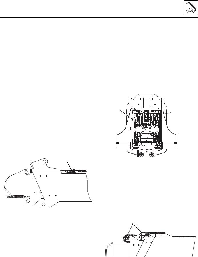
Boom
Remove the boom from supports and install the remaining wear pads to the second boom section. Do not shim or tighten bolts at this time.
14.Install the grease fittings for the wear pad and chain roller assembly.
3.3.7Second Boom Section Installation
1.Install the top, bottom and side rear wear pads onto the second boom section. Do not shim or tighten the bolts and this time.
2.Lubricate the inside of the first boom section on areas where the second boom section wear pads will slide.
3.Attach the chain clevis (3) to the rear of the third boom section.
4.Using a suitable sling, balance the second, third and fourth boom sections and carefully slide 3-4 ft into the front of the first boom section. Set the second, third and fourth boom sections on a suitable support and reset the sling under the boom head of the fourth boom section. Carefully slide the three boom sections into the first boom section. Leave 6-8 in of the two boom sections out to be able to install the wear pad block and the wear pads in the front of the first boom section.
5.Install the chain adjustment block (4) to the bottom of the boom.
4
MX0440
6.With the boom still supported, install the top wear pads in the front of the first boom section. Remove the boom from supports and install the remaining wear pads to the first boom section. Do not shim or tighten bolts at this time.
7.Lubricate the retract chain on the bottom of the second boom section.
8.Install the lube fittings to the wear pad and chain roller assembly.
G10-55A & G12-55A AccuPlace
9.Connect the chain clevis (5) to the second boom section.
10.Assemble the rear bottom chain roller to the second boom section.
11.Shim all wear pads needed to obtain the minimum gap of 1/16 in (1,6 mm). Tighten all wear pad bolts to the correct values. Refer to Section 3.7, “Boom Wear Pads.”
12.Install the hose sheave to the second boom section.
13.Attach the hoses, and optional auxiliary hoses and electrical cable to the hose carrier at the rear of the boom.
14.At the rear of the boom, install the bracket (6) to the back of the hose carrier.
6


 5
5
MAP0670
15.Install the hose guide bracket for the electric and hydraulic options at the rear of the boom.
16.Attach the chain clevis to the chain.
17.Install the hoses to the hose carrier at the rear of the boom.
18.Install the hose guide bracket to the rear of the second boom section.
19.Install the optional hydraulics and electrical cables if equipped.
20.Connect the hose assembly to the take-up weldment.
7
MY1720
3.7
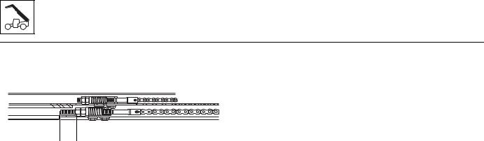
Boom
21.Install the top front chain roller (7) to the second and third boom sections.
MAP0740
8
22.Install the cushion clamps around the hoses on the first boom section.
23.Connect the top front chain clevises to the chains, then connect the chains to the first and second boom sections.
24.Adjust the retract chain (8) at the bottom front of the first boom section to 2 7/8 in. (73 mm) for the initial setup.
25.Install the auxiliary hydraulic hoses and electrical cables to the boomhead of the fourth boom section.
26.Using a suitable sling, install the tilt cylinder to the front of the boom.
27.Using a suitable sling, install the extend/retract cylinder and support to the second and first boom section.
28.Reconnect the latch on the Boom Length Sensor cable to the third boom section. Refer to Section 9.11.13, “Boom Length Sensor.”
3.3.8Boom Installation
1.Park the machine on a hard, level surface, place the transmission control lever in (N) NEUTRAL, engage the park brake, chock the wheels and shut the engine OFF.
2.Using suitable slings, balance the boom assembly, lift and carefully guide the boom into place. Align the frame pivot bore with the boom assembly pivot bore. Install the boom pivot pin.
3.With the sling still in place, install the compensation cylinder, pins and bolts.
4.With the sling still in place, install the rod end of the left lift/lower cylinder, pin and lock bolt. Repeat for the right side lift/lower cylinder.
Note: Raising the boom up or down with the sling may be necessary so the boom, compensation and lift/lower cylinder bores can be aligned for easier pin installation.
Note: Grease the boom pivot bore, compensation cylinder rod ends, lift/lower cylinder rod end and pins before installing.
5.Uncap and reconnect the previously labeled hydraulic hoses to the extend/retract cylinder.
6.Uncap and connect any remaining hydraulic fittings to their appropriate locations.
7.Recheck the wear pad gaps to ensure they meet the minimum gap requirement. Shim if necessary.
8.Ensure that the boom chains are properly adjusted. Refer to Section 3.5, “Boom Section Separation Adjustment.”
9.Install and reconnect the boom angle sensors to both the left and right side of the boom. Refer to Section 9.11.12, “Boom Angle Sensors.”
10.Connect the battery negative (-) cable to the battery negative (-) terminal.
11.Start the engine and operate all boom functions several times. Check for leaks, and check the hydraulic fluid level in the reservoir; add fluid if required.
12.Clean up all debris, hydraulic fluid, etc., in, on, near and around the machine.
13.Close and secure the engine cover.
3.8 |
G10-55A & G12-55A AccuPlace |
Loading...