


Operation & Safety
An Oshkosh Corporation Company
Manual
Original Instructions
Keep this manual with machine at all times.
Models
G10-55A
G12-55A
Before S/N 0160045636 excluding
0160045082, 0160045094,
0160045209, 0160045295,
0160045296, 0160045449
3126018
Revised
May 3, 2012

CALIFORNIA PROPOSITION 65
BATTERY WARNING
Battery posts,
terminals and related
accessories contain
lead and lead compounds,
chemical known to the
State of California
to cause cancer and
reproductive harm.
WASH HANDS
AFTER HANDLING!
CALIFORNIA PROPOSITION 65
EXHAUST WARNING
Diesel Engine exhaust and
some of its constituents
are known to the State of
California to cause cancer,
birth defects and other
reproductive harm.

Revision Log
Revision Log
July 9, 2004 - A - Original Issue of Manual
August 8, 2007 - B - Revised manual and added Tier III information.
November 13, 2008 - C - Revised manual.
January 5, 2010 - D - Revised covers and pages b, 1-5, 1-6, 2-1, 2-6, 3-6, 3-14, 4-1,
4-3, 4-5, 4-7, 5-3, 5-4, 5-5, 5-19, 5-20, 5-22, 5-24, 5-26, 5-28, 5-30 thru 5-33, 5-36,
5-38, 5-39, 5-40, 5-42, 7-2, 7-3, 7-5, 7-16, 7-19, 7-21, 8-1, 9-1, 9-2 & 9-4.
July 19, 2010 - E - Revised pages 1-9, 2-3, 2-4, 2-7, 2-9, 3-1, 3-2, 3-4, 3-5, 4-1 thru
4-4, 4-10, 4-11, 5-40, 6-1, 7-2 thru 7-5, 7-7, 7-8, 7-10 thru 7-15, 7-18 thru 7-22, 9-1,
9-5 & 9-6.
December 21, 2010 - F - Revised pages 7-16, 9-3 & 9-6.
August 5, 2011 - G - Revised pages 2-3 thru 2-11 & 7-2.
May 3, 2012 - H - Revised covers and pages 5-5, 5-24, 5-24 thru 5-27 & 7-1.
REVISION LOG
a3126018

Read This First
Read This First
This manual is a very important tool! Keep it with the machine at all times.
The purpose of this manual is to provide owners, users, operators, lessors, and
lessees with the precautions and operating procedures essential for the safe and
proper machine operation for its intended purpose.
Due to continuous product improvements, JLG Industries, Inc. reserves the right to
make specification changes without prior notification. Contact JLG Industries, Inc.
for updated information.
Operator Qualifications
The operator of the machine must not operate the machine until this manual has
been read, training is accomplished and operation of the machine has been
completed under the supervision of an experienced and qualified operator.
Operation within the U.S.A. requires training per OSHA 1910.178.
Operators of this equipment must possess a valid, applicable driver’s license, be in
good physical and mental condition, have normal reflexes and reaction time, good
vision and depth perception and normal hearing. Operator must not be using
medication which could impair abilities nor be under the influence of alcohol or any
other intoxicant during the work shift.
In addition, the operator must read, understand and comply with instructions
contained in the following material furnished with the telehandler:
• This Operation & Safety Manual
• Telehandler Safety Manual (ANSI only)
• All instructional decals and plates
• Any optional equipment instructions furnished
The operator must also read, understand and comply with all applicable Employer,
Industry and Governmental rules, standards and regulations.
Modifications
Any modification to this machine must be approved by JLG.
b 3126018

Read This First
This product must comply with all safety related bulletins. Contact JLG Industries,
Inc. or the local authorized JLG representative for information regarding safetyrelated bulletins which may have been issued for this product.
JLG Industries, Inc. sends safety related bulletins to the owner of record of this
machine. Contact JLG Industries, Inc. to ensure that the current owner records are
updated and accurate.
JLG Industries, Inc. must be notified immediately in all instances where JLG
products have been involved in an accident involving bodily injury or death of
personnel or when damage has occurred to personal property or the JLG product.
FOR:
• Accident Reporting and Product Safety Publications
• Current Owner Updates
• Questions Regarding Product Applications and Safety
• Standards and Regulations Compliance Information
• Questions Regarding Product Modifications
CONTACT:
Product Safety and Reliability Department
JLG Industries, Inc.
13224 Fountainhead Plaza
Hagerstown, MD 21742
USA
or Your Local JLG Office
(Addresses on back cover)
In USA:
Toll Free: 1-877-JLG-SAFE (1-877-554-7233)
Outside USA:
Phone: +1-717-485-6591
E-mail:
ProductSafety@JLG.com
c3126018

Read This First
Other Publications Available
Service Manual............................................................................................3126019
Illustrated Parts Manual...............................................................................3126020
Note: The following standards may be referenced in this manual:
ANSI is compliant to ANSI/ITSDF B56.6
AUS is compliant to AS 1418.19
CE is compliant to EN1459
Refer to the machine Serial Number Plate to identify the applicable compliance
standard.
d 3126018

Table of Contents
TABLE OF CONTENTS
Revision Log
Read This First
Operator Qualifications ...................................................... b
Modifications ...................................................................... b
Other Publications Available .............................................. d
Table of Contents
Section 1 - General Safety Practices
1.1 Hazard Classification System ..............................................1-1
Safety Alert System and Safety Signal Words................1-1
1.2 General Precautions ............................................................1-1
1.3 Operation Safety ..................................................................1-2
Electrical Hazards ...........................................................1-2
Tip Over Hazard..............................................................1-3
Travel Hazard ................................................................. 1-6
Load Falling Hazard ........................................................1-7
Lifting Personnel .............................................................1-8
Driving Hazards on Slopes .............................................1-9
Pinch Points and Crush Hazards ..................................1-10
Fall Hazard....................................................................1-12
Chemical Hazards.........................................................1-13
Table of Contents
Section 2 - Pre-Operation and Inspection
2.1 Pre-Operation Check and Inspection...................................2-1
2.2 Safety Decals .......................................................................2-3
ANSI................................................................................2-3
ISO (S/N 0160040120 & After, If Equipped) ...................2-9
2.3 Walk-Around Inspection.....................................................2-12
2.4 Warm-Up and Operational Checks ....................................2-14
Warm-Up Check ...........................................................2-14
Operational Check ........................................................2-14
2.5 Operator Cab .....................................................................2-15
2.6 Windows ............................................................................2-16
Cab Door Window (if equipped)....................................2-16
Section 3 - Controls and Indicators
3.1 General ................................................................................3-1
3.2 Controls ...............................................................................3-2
Dash Controls and Indicators..........................................3-4
Ignition ............................................................................3-6
Park Brake ......................................................................3-7
Parking Procedure ..........................................................3-7
i3126018

Table of Contents
Transmission Control Lever............................................ 3-8
Boom Joystick .............................................................. 3-10
Frame Level Joystick.................................................... 3-11
Auxiliary Hydraulic Joystick (if equipped) ..................... 3-12
Outrigger Joysticks ....................................................... 3-13
Right Hand Panel ......................................................... 3-14
Accessory Control Lever (if equipped) ......................... 3-15
3.3 Steer Modes ...................................................................... 3-16
Steer Mode Change ..................................................... 3-16
3.4 Operator Seat.................................................................... 3-17
Adjustments.................................................................. 3-17
Seat Belt ....................................................................... 3-18
3.5 Boom Angle and Extension Indicators .............................. 3-19
Section 4 - Operation
4.1 Engine ................................................................................. 4-1
Starting the Engine ......................................................... 4-1
Cold Weather Starting Aids ............................................ 4-2
Extreme Cold Weather Starting (if equipped) ................. 4-3
Battery Boosted Starting................................................. 4-4
Normal Engine Operation ............................................... 4-5
Shut-Down Procedure .................................................... 4-5
4.2 Operating with a Non-Suspended Load .............................. 4-6
Lift Load Safely............................................................... 4-6
Picking Up a Load .......................................................... 4-6
Transporting a Load ....................................................... 4-7
Leveling Procedure......................................................... 4-7
Placing a Load................................................................ 4-8
Disengaging a Load........................................................ 4-8
4.3 Operating with a Suspended Load ...................................... 4-9
Lift Load Safely............................................................... 4-9
Picking Up a Suspended Load ....................................... 4-9
Transporting a Suspended Load .................................. 4-10
Leveling Procedure....................................................... 4-10
Placing a Suspended Load........................................... 4-11
Disengaging a Suspended Load .................................. 4-11
4.4 Loading and Securing for Transport .................................. 4-12
Tiedown ........................................................................ 4-12
Lifting ............................................................................ 4-13
ii 3126018

Section 5 - Attachments
5.1 Approved Attachments ........................................................ 5-1
5.2 Unapproved Attachments ....................................................5-2
5.3 JLG Supplied Attachments .................................................. 5-3
Before S/N 0160037689 .................................................5-3
S/N 0160037689 & After .................................................5-5
5.4 Telehandler/Attachment/Fork Capacity................................ 5-6
5.5 Use of the Capacity Chart....................................................5-7
Capacity Indicator Locations ...........................................5-7
Sample Capacity Chart ...................................................5-8
Example ........................................................................5-12
5.6 Attachment Installation ......................................................5-13
Hydraulic Operated Attachment ....................................5-16
5.7 Adjusting/Moving Forks......................................................5-17
5.8 Attachment Operation ........................................................5-18
Carriage w/Forks...........................................................5-19
Side Tilt Carriage .......................................................... 5-20
Swing Carriage .............................................................5-22
Dual Fork Positioning Carriage .....................................5-24
Fork Extension ..............................................................5-26
Mast Carriage ...............................................................5-28
Mast Carriage w/Swing and Side Shift
(Before S/N 0160037689) .............................................5-30
Mast Carriage w/Side Tilt
(S/N 0160037689 & After).............................................5-32
Fork Mounted Hook ......................................................5-34
Truss Boom...................................................................5-36
Bucket ...........................................................................5-38
Grapple Bucket .............................................................5-40
Personnel Work Platform - Quick Switch Mounted
(Before S/N 0160037689) .............................................5-42
Personnel Work Platform - Fork Mounted.....................5-44
Boom Head-Mounted Winch
(Before S/N 0160037689) .............................................5-46
Table of Contents
Section 6 - Emergency Procedures
6.1 Towing a Disabled Product ..................................................6-1
Moving Short Distances ..................................................6-1
Moving Longer Distances ............................................... 6-1
6.2 Emergency Lowering of Boom.............................................6-2
6.3 Emergency Exit from Enclosed Cab ....................................6-2
iii3126018

Table of Contents
Section 7 - Lubrication and Maintenance
7.1 Introduction.......................................................................... 7-1
Clothing and Safety Gear ............................................... 7-1
7.2 General Maintenance Instructions....................................... 7-2
7.3 Service and Maintenance Schedule .................................... 7-3
10 & 1st 50 and 50 Hour Maintenance Schedule........... 7-3
1st 250, 250 & 500 Hour Maintenance Schedule........... 7-4
1000 & 1500 Hour Maintenance Schedule..................... 7-5
7.4 Lubrication Schedules ......................................................... 7-6
50 Hour Lubrication Schedule ........................................ 7-6
250 Hour Lubrication Schedule ...................................... 7-7
1000 Hour Lubrication Schedule .................................... 7-8
7.5 Operator Maintenance Instructions ................................... 7-10
Fuel System.................................................................. 7-10
Air Intake System ......................................................... 7-12
Engine Oil ..................................................................... 7-14
Hydraulic Oil ................................................................. 7-15
Tires.............................................................................. 7-16
Transmission Oil........................................................... 7-19
Hydraulic Return Filter (Before S/N 0160039451
excluding 0160039394 & 0160039397)........................ 7-20
Engine Cooling System ................................................ 7-21
Battery .......................................................................... 7-22
Windshield Washer System (if equipped)..................... 7-23
Section 8 - Additional Checks
8.1 Auto-Frame Level System (Before S/N 0160038592)......... 8-1
Section 9 - Specifications
9.1 Product Specifications......................................................... 9-1
Capacities....................................................................... 9-1
Tires................................................................................ 9-3
Performance ................................................................... 9-4
Dimensions..................................................................... 9-5
Index
Inspection, Maintenance and Repair Log
iv 3126018
Section 1 - General Safety Practices
DANGER
OW0010
WARNING
OW0021
CAUTION
OW0031
SECTION 1 - GENERAL SAFETY PRACTICES
1.1 HAZARD CLASSIFICATION SYSTEM
Safety Alert System and Safety Signal Words
DANGER indicates an imminently hazardous situation which, if not avoided, will
result in death or serious injury.
WARNIN G indicates a potentially hazardous situation which, if not avoided, could
result in death or serious injury.
CAUTION indicates a potentiality hazardous situation which, if not avoided, may
result in minor or moderate injury.
1.2 GENERAL PRECAUTIONS
WARNING
Before operation, read and understand this manual. Failure to comply with the
safety precautions listed in this manual could result in machine damage, property
damage, personal injury or death.
1-13126018
Section 1 - General Safety Practices
OW0040
10 FT
(3 M)
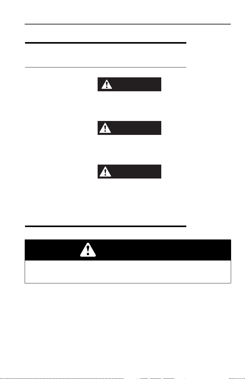
1.3 OPERATION SAFETY
Electrical Hazards
• This machine is not insulated and does not provide protection from contact or
being near electrical current.
• NEVER operate the telehandler in an area where overhead power lines,
overhead or underground cables, or other power sources may exist without
ensuring the appropriate power or utility company de-energizes the lines.
• Always check for power lines before raising the boom.
• Follow employer, local and governmental regulations for clearance from
powerlines.
1-2 3126018
Section 1 - General Safety Practices
OW0050
OW0080
OW0100
4 FT
(1,2 M)
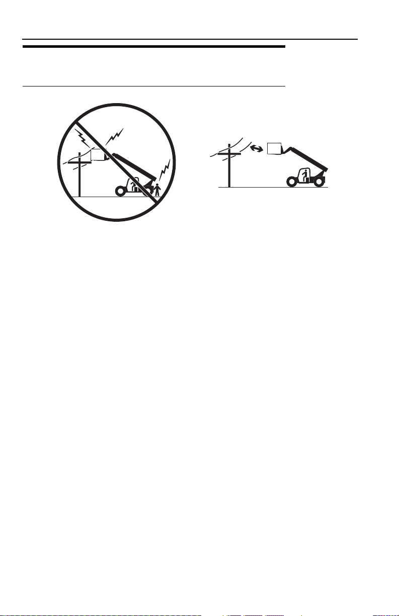
Tip Over Hazard
General
• For additional load requirements, refer to the appropriate capacity chart.
• Never use an attachment without the appropriate JLG approved capacity chart
installed on the telehandler.
• Understand how to properly use the capacity charts located in cab.
• DO NOT exceed rated lift capacity.
• Be sure that the ground conditions are able to support the machine.
• DO NOT raise boom unless frame is level (0 degrees), unless otherwise noted
on capacity chart.
• DO NOT level machine with boom/attachment above 4 ft (1,2 m).
(AUS - DO NOT level machine with load more than 11.8 in (300 mm) above
ground surface.)
1-33126018

Section 1 - General Safety Practices
OH2291
OH
20911
OH2221
• MAINTAIN proper tire pressure at all times. If proper tire pressures are not
maintained, this machine could tip over.
• Refer to manufacturer’s specifications for proper fill ratio and pressure
requirements for tires equipped with ballast.
• Always wear the seat belt.
• Keep head, arms, hands, legs and all other body parts inside operator’s cab at all
times.
If the telehandler starts to tip over:
• DO NOT JUMP
• BRACE YOURSELF and STAY WITH THE MACHINE
• KEEP YOUR SEAT BELT FASTENED
• HOLD ON FIRMLY
• LEAN AWAY FROM THE POINT OF IMPACT
1-4 3126018
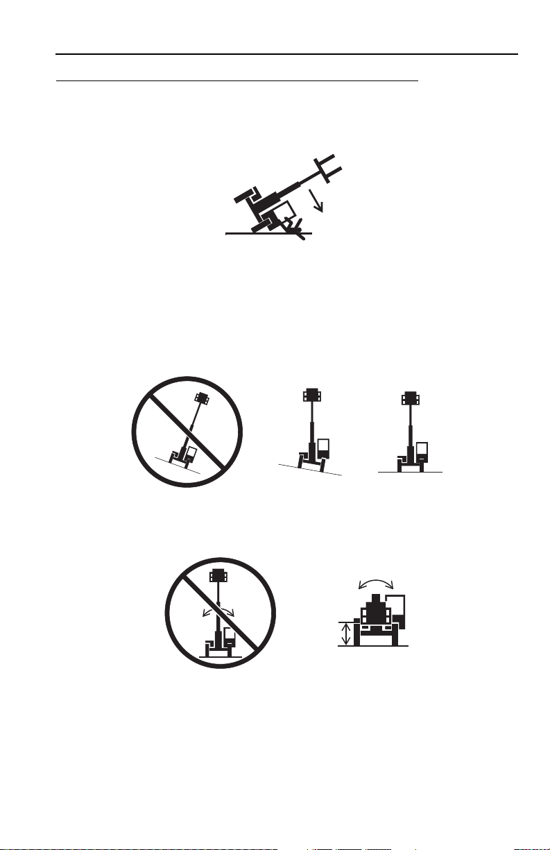
Non-Suspended Load
OW0060
OW0150
• DO NOT drive with boom raised.
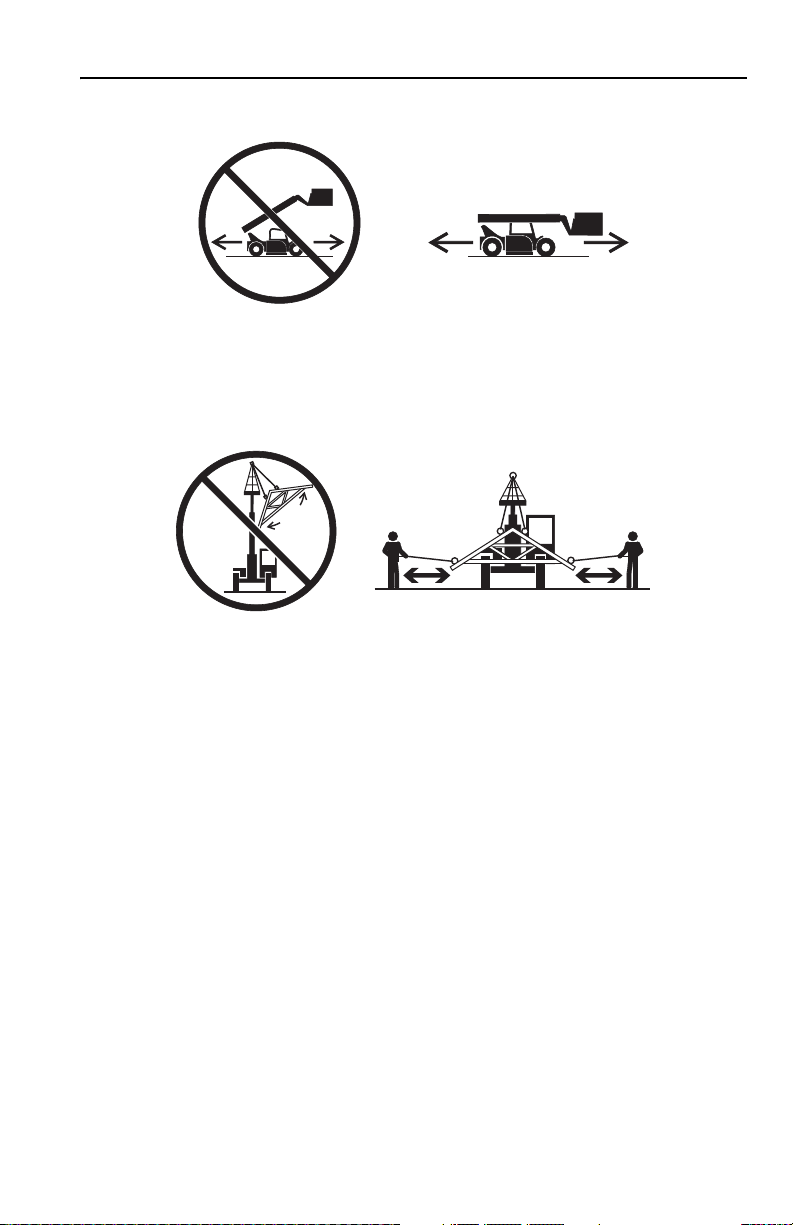
Suspended Load
Section 1 - General Safety Practices
• Tether suspended loads to restrict movement.
• Weight of all rigging (slings, etc.) must be included as part of load.
• Beware of wind. Wind can cause a suspended load to swing and cause
dangerous side loads - even with tag lines.
• DO NOT attempt to use telehandler frame-leveling to compensate for load swing.
• Keep heavy part of load closest to attachment.
• Never drag the load; lift vertically.
When driving with a suspended load:
• Start, travel, turn and stop slowly to prevent load from swinging.
• DO NOT extend boom.
• DO NOT raise the load more than 11.8 in (300 mm) above ground surface or
the boom more than 45°.
• DO NOT exceed walking speed.
1-53126018

Section 1 - General Safety Practices
OAL2030
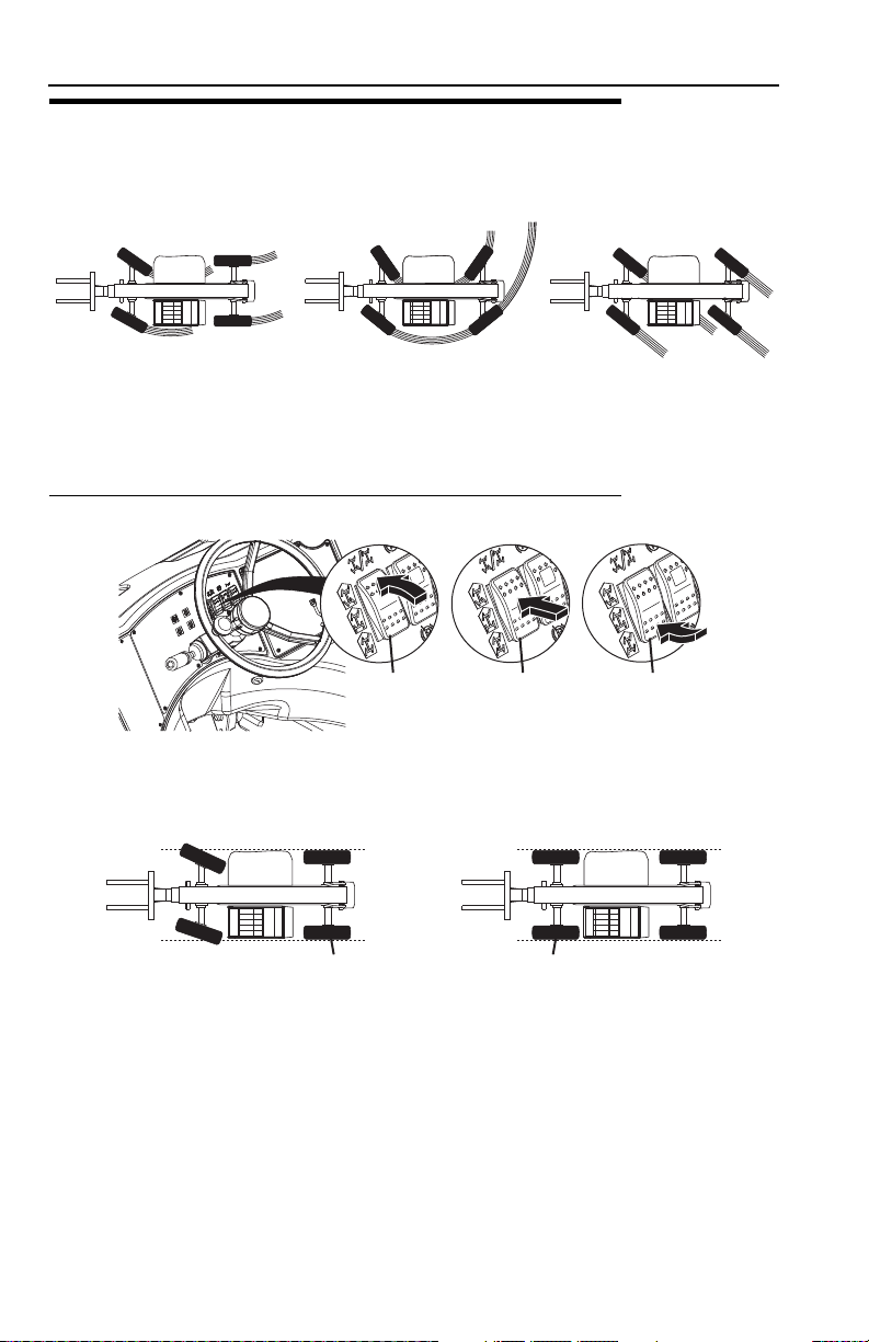
2-Wheel Front Steer 4-Wheel Circle Steer 4-Wheel Crab Steer
Travel Hazard
• Steering characteristics differ between steer modes. Identify the steer mode
settings of the telehandler being operated.
• DO NOT change steer modes while traveling. Steer modes must be changed
while telehandler is stationary.
• Visually verify proper wheel alignment after each steer mode change.
• Ensure that adequate clearance is provided for both rear tail swing and front fork
swing.
• Look out for and avoid other personnel, machinery and vehicles in the area. Use
a spotter if you DO NOT have a clear view.
• Before moving be sure of a clear path and sound horn.
• When driving, retract boom and keep boom/attachment as low as possible while
maintaining visibility of mirrors and maximum visibility of path of travel.
• Always look in the direction of travel.
• Always check boom clearances carefully before driving underneath overhead
obstructions. Position attachment/load to clear obstacles.
• When driving in high speed, use only front wheel steer (if steering modes are
selectable).
1-6 3126018

Section 1 - General Safety Practices
OW0130
Load Falling Hazard
• Never suspend load from forks or other parts of carriage.
• DO NOT burn or drill holes in fork(s).
• Forks must be centered under load and spaced apart as far as possible.
1-73126018

Section 1 - General Safety Practices
OW0170
OW0190
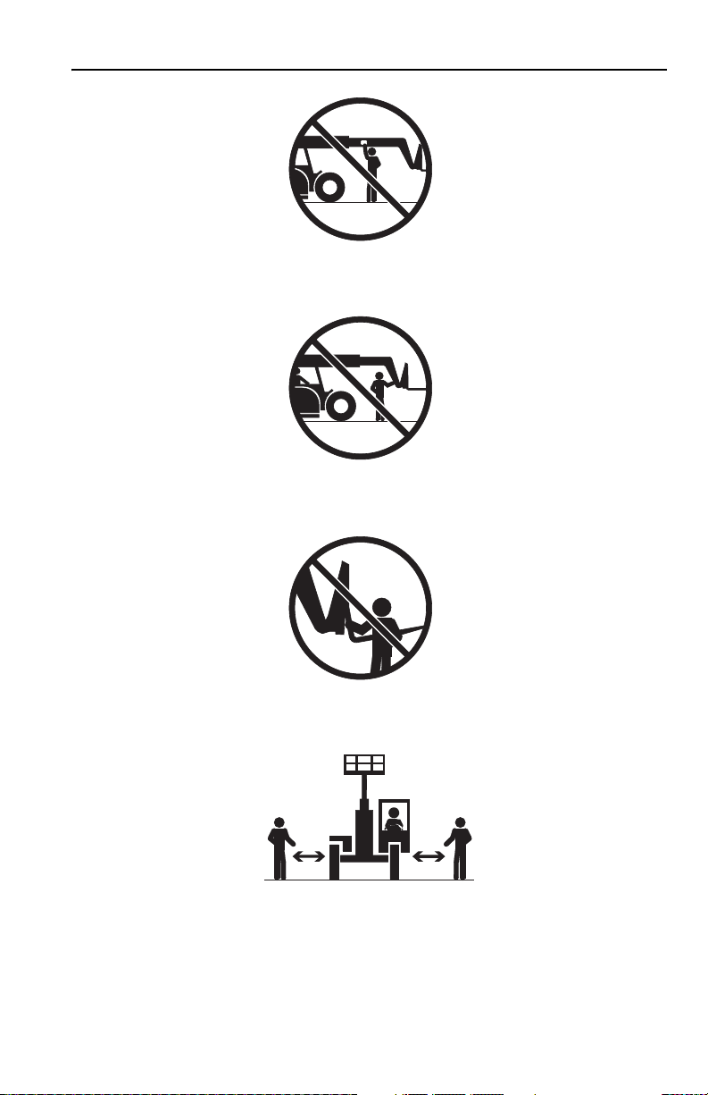
Lifting Personnel
• When lifting personnel, USE ONLY a JLG approved personnel work platform,
with proper capacity chart displayed in the cab.
• DO NOT drive machine from cab when personnel are in platform.
1-8 3126018

Section 1 - General Safety Practices
OW0200
Driving Hazards on Slopes
To maintain sufficient traction and braking capabilities, travel on slopes as follows:
• When unloaded, drive with forks pointed downhill.
• When loaded, drive with the forks pointed uphill.
• For additional travel requirements, refer to the appropriate capacity chart.
• To avoid overspeeding the engine and drivetrain when driving down slopes,
downshift to a lower gear and use the service brake as necessary to maintain a
slow speed. DO NOT shift into neutral and coast downhill.
• Avoid excessively steep slopes or unstable surfaces. To avoid tip over DO NOT
drive across excessively steep slopes under any circumstances.
• Avoid turning on a slope. Never engage “inching” or shift to “Neutral” when going
downhill.
• DO NOT park on a slope.
1-93126018
Section 1 - General Safety Practices
OW0210
OW0220
OW0230
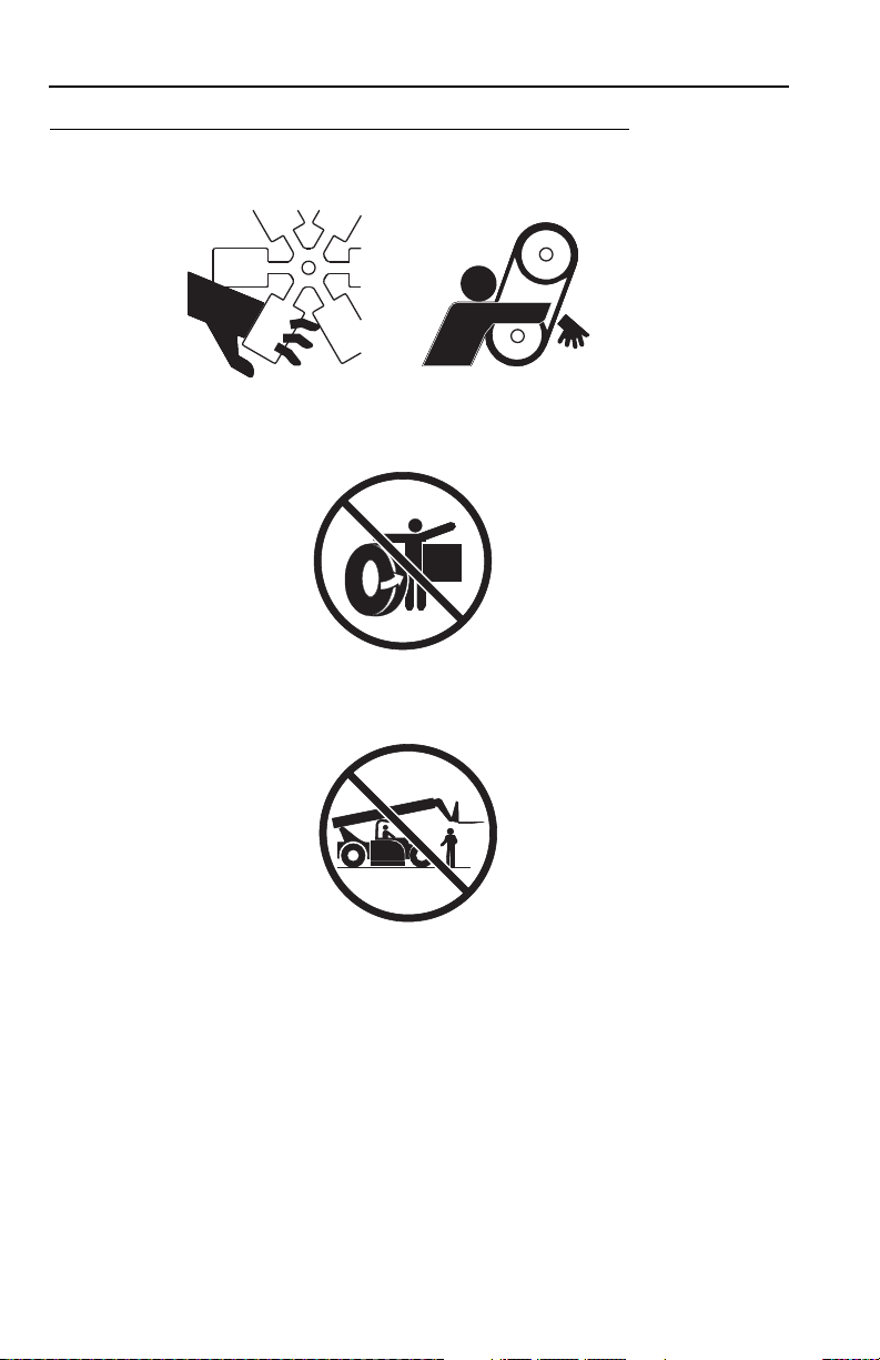
Pinch Points and Crush Hazards
Stay clear of pinch points and rotating parts on the telehandler.
• Stay clear of moving parts while engine is running.
• Keep clear of steering tires and frame or other objects.
• Keep clear from under boom.
1-10 3126018
Section 1 - General Safety Practices
OW0240
OW0250
OW0260
OW0960
• Keep clear of boom holes.
• Keep arms and hands clear of attachment tilt cylinder.
• Keep hands and fingers clear of carriage and forks.
• Keep others away while operating.
1-113126018

Section 1 - General Safety Practices
OW0280
OW0290
Fall Hazard
• Enter using the proper hand holds and steps provided. Always maintain 3-point
contact when mounting or dismounting. Never grab control levers or steering
wheel when mounting or dismounting the machine.
• DO NOT get off the machine until the shutdown procedure on page 4-5 has been
performed.
• DO NOT carry riders. Riders could fall off machine causing death or serious
injury.
1-12 3126018

Section 1 - General Safety Practices
OW0300
OW0950
Chemical Hazards
Exhaust Fumes
• DO NOT operate machine in an enclosed area without proper ventilation.
• DO NOT operate the machine in hazardous environments unless approved for
that purpose by JLG and site owner. Sparks from the electrical system and the
engine exhaust can cause an explosion.
• If spark arrestors are required, ensure they are in place and in good working
order.
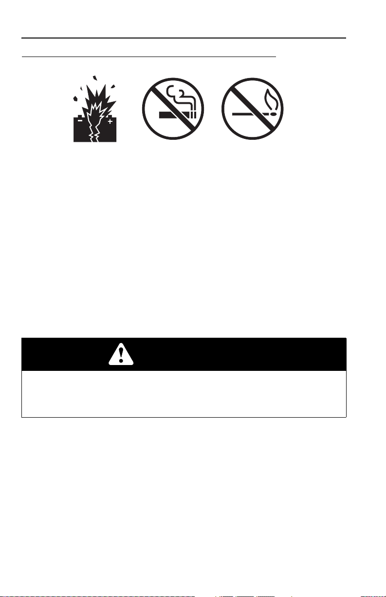
Flammable Fuel
• DO NOT fill the fuel tank or service the fuel system near an open flame, sparks
or smoking materials. Engine fuel is flammable and can cause a fire and/or
explosion.
Hydraulic Fluid
• DO NOT attempt to repair or tighten any hydraulic hoses or fittings while the
engine is running or when the hydraulic system is under pressure.
• Stop engine and relieve trapped pressure. Fluid in the hydraulic system is under
enough pressure that it can penetrate the skin.
• DO NOT use your hand to check for leaks. Use a piece of cardboard or paper to
search for leaks. Wear gloves to protect hands from spraying fluid.
1-133126018

Section 1 - General Safety Practices
This Page Intentionally Left Blank
1-14 3126018
Section 2 - Pre-Operation and Inspection
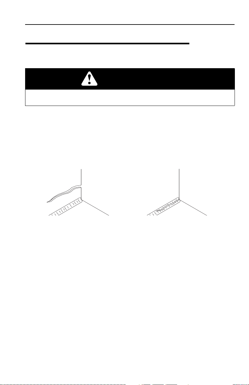
OAH1000
PARENT METAL CRACK WELD CRACK
SECTION 2 - PRE-OPERATION AND INSPECTION
2.1 PRE-OPERATION CHECK AND INSPECTION
Note: Complete all required maintenance before operating unit.
WARNING
FALL HAZARD. Use extreme caution when checking items beyond your normal
reach. Use an approved ladder.
The pre-operation check and inspection, performed at beginning of each work shift
or at each change of operator, should include the following:
1. Cleanliness - Check all surfaces for leakage (oil, fuel or battery fluid) or foreign
objects. Report any leakage to the proper maintenance personnel.
2. Structure - Inspect the machine structure for dents, damage, weld or parent
metal cracks or other discrepancies.
3. Safety Decals - Ensure all safety decals are legible and in place. Clean or
replace as required. See page 2-3 for details.
4. Operation and Safety Manuals - Operation & Safety Manual and AEM Safety
Manual (ANSI only) are located in cab manual holder.
5. Walk-Around Inspection - See page 2-12 for details.
6. Fluid Levels - Check fluids, including fuel, hydraulic oil, engine oil, transmission
fluid and coolant. When adding fluids, refer to Section 7 - Lubrication and
Maintenance and Section 9 - Specifications to determine proper type and
intervals. Before removing filler caps or fill plugs, wipe all dirt and grease away
from the ports. If dirt enters these ports, it can severely reduce component life.
7. Attachments/Accessories - Ensure correct capacity charts are installed on the
telehandler. If provided, reference the Operation & Safety Manual of each
attachment or accessory installed for specific inspection, operation and
maintenance instructions.
2-13126018

Section 2 - Pre-Operation and Inspection
8. Operational Check - Once the walk-around inspection is complete, perform a
warm-up and operational check (see page 2-14) of all systems in an area free
of overhead and ground level obstructions. See Section 3 - Controls and
Indicators for more specific operating instructions.
WARNING
If telehandler does not operate properly, immediately bring machine to a stop,
lower boom and attachment to ground and stop the engine. Determine cause and
correct before continued use.
2-2 3126018
OW0334
91503108
9150-3108 REV -
MOVING PARTS could
crush causing death
or serious injury.
Keep clear of wheels and
moving parts while engine
is running.
1705881
91503112
9150-3112 REV -
91503109
9150-3109 REV -
NO RIDERS. Riders could FALL OFF
machine causing death or serious injury.
91513208
9151-3208 REV -
When lifting personnel, USE ONLY a Gradall manufactured
personnel work platform, with proper personnel work
platform CAPACITY CHART DISPLAYED in cab.
READ AND UNDERSTAND personnel work platform Owner/Operator
manual before lifting personnel.
DO NOT DRIVE machine from cab when personnel are on platform.
All personnel on platform must WEAR A FULL BODY HARNESS,
with lanyard attached to a designated anchorage point.
When personnel are on platform, the OPERATOR MUST REMAIN
SEATED in cab with personnel in direct line of sight.
OPERATE CONTROLS CAUTIOUSLY and lightly when lifting or
positioning personnel.
Failure to comply could result in death or serious injury.
1701505
(BEFORE
S/N 0160016100)
1
2
3
4
GEAR
9156-3246 REV A
Down-shift to a lower gear when descending.
Overspeeding of drivetrain could result in
equipment damage or personal injury.
91563246
9150-3108 REV -
MOVING PARTS could
crush causing death
or serious injury.
Keep clear of wheels and
moving parts while engine
is running.
91503108
DO NOT use Ether or
other high energy
starting aids.
Engine equipped with
Pre-heating system.
ENGINE EXPLOSION
could result in death
or serious injury.
1706300C
1706300
(PERKINS ENGINE ONLY -
BEFORE S/N 0160039451
EXCLUDING 0160039394
& 0160039397)
91503098
9150-3098 REV. A
For safe operation of machine, and to minimize risk of
serious injury, READ AND OBSERVE the following:
6. Keep others away from machine when operating. Do not
allow others to stand under boom or load. Always look in
direction of travel.
7. Use extreme care when handling long, high or wide loads.
Do not handle unstable or loosely stacked loads.
8. Forks must be centered under load, and spaced apart as far
as possible.
9. Level machine before lifting any load above 4 feet (1.2m).
10. Improper use of machine could result in machine tipping
over. If machine starts to tip over, do not leave operator's
seat. Lean away from tip, and brace yourself.
11. Keep mirror(s) clean and properly adjusted. Objects in
mirror(s) are closer than they appear.
5. On inclines, travel with load up-grade.
1. Only trained and authorized personnel may operate this
machine.
2. Before operating, read and understand all capacity charts,
operator manual and safety manuals.
3. Operator must be seated with seat belt fastened. Assure all
controls are in neutral before ignition switch is turned on.
4. Do not travel with boom raised. When traveling, fully
retract boom and place forks in carry position, which is
approximately 4 feet (1.2 m) above ground. Tilt carriage
back slightly to cradle load. Use extreme caution when
turning.
91503110
CONTACTING ELECTRIC POWER
LINES will result in death
or serious injury.
Do not place machine or load
within 10 feet (3m) of electric
9150-3110 REV - A
power lines.
10 FT.
(3 M)
91513201
9151-3201 REV. (-)
91413061
91163028
4
A
A
A
A
1000
A
A
A
A
A
A
B
1001121126
10
D
50
250
50
1001121125A
LB
FT
(
N
m)
1001121125
S/N 0160039451 THRU 0160040119
INCLUDING 0160039394 & 0160039397
VIEW OF CAB DASH
CAPACITY
CHARTS
Section 2 - Pre-Operation and Inspection
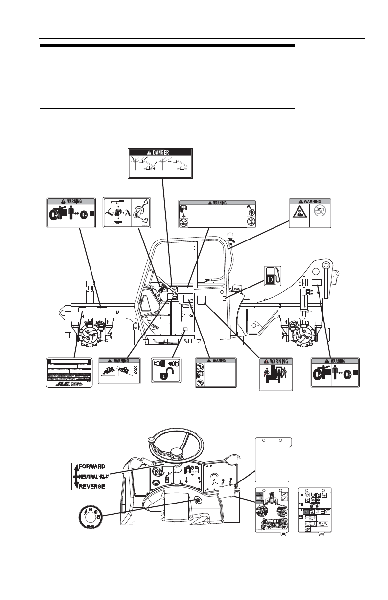
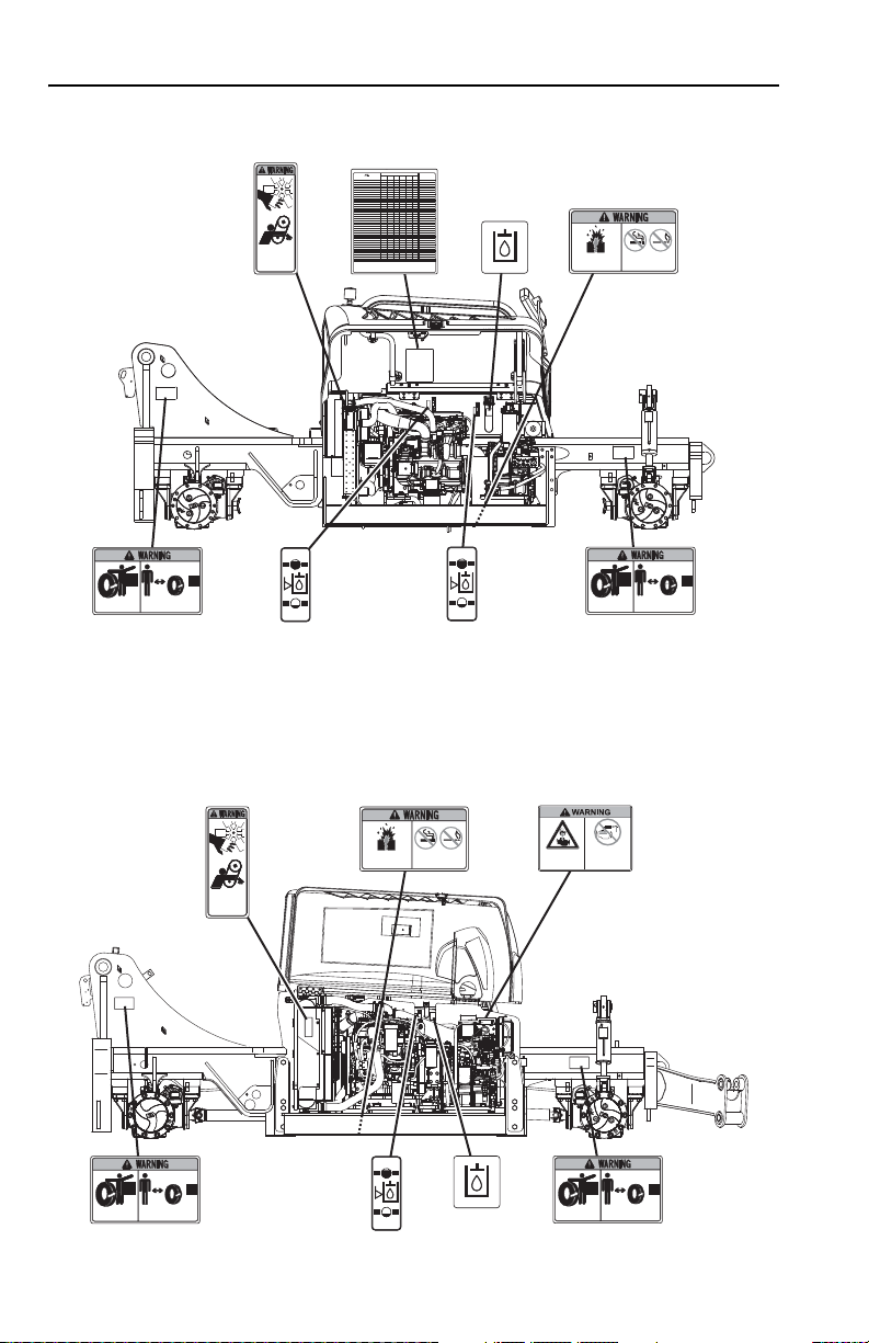
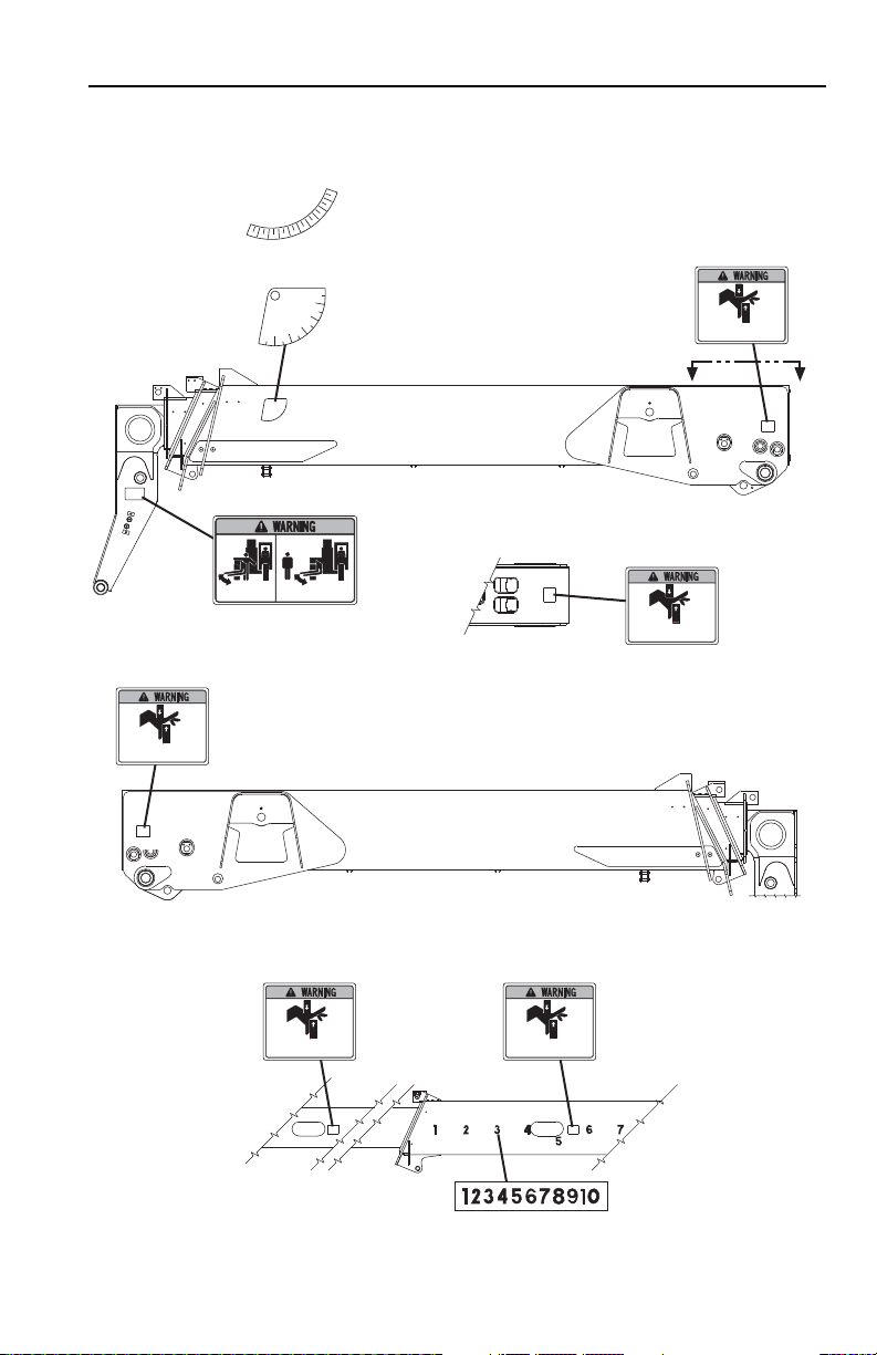
2.2 SAFETY DECALS
Ensure all DANGER, WARNING, CAUTION and instructional decals and proper
capacity charts are legible and in place. Clean and replace as required.
ANSI
Before S/N 0160040120
2-33126018
Section 2 - Pre-Operation and Inspection
OY2011
9150-3097 REV. -
MOVING PARTS can
cut or entangle. Keep
clear while engine is
running.
91503097
Diesel Engine
SERVICE INTERVALS
LUBRICATION AND MAINTENANCE
MATERIAL HANDLER
9156-3227 REV(A)
Air Cleaner Element
Fuel Filter
Engine Oil Filter
Engine Oil
Coolant
Diesel Fuel
Transmission
Lubricant
Filter
Transfer Case
Lubricant
Center Section
Axle Lubricant
Planetary Hubs
Filter
Lubricant
Hydraulic System
Breather/Filter
Grease Fittings
Axles (6 Pts. Ea.)
Boom Head Pivot (2 Pts.)
Boom Pivot (2 Pts.)
Extend Chain Sheave (1 Pt.)
Drive Shafts (1 Pt. Ea.)
Cylinder Pins(13 Pts.)
Quick Switch Pin (1 Pt.)
Retract Chain Sheave (1 Pt.)
Boom
Front Bottom Bearing Pads
All Other Bearing Pads
Extend/Retract Chains
Options And Attachments
Stabilizer Cylinder (3 Pts.)
Attachment Pivots And Pins
Tires
14.00R24 12 Radial
17.5-25 12 Ply
17.5R25 Radial
Lug Nut Torque
Torque
Check
Check
Check
Check
Check
Check
Check
Check
Check
Check
Check
Check
Check
Check
Grease
Grease
Grease
Grease
Grease
Grease
Grease
Grease
Grease
Grease
Grease
Grease
Change
Change
Change
Change
Change
Change
Change
Change
Change
Change
Change
Change
SAE 15W-40 CE Oil
Etheylene Glycol
No. 2 Diesel Fuel
Mobil 424
Mobil 424
Mobil 424
Mobil 424
Mobil 424
Mystik Tetrimoly
Mystik Tetrimoly
Mystik Tetrimoly
Mystik Tetrimoly
Mystik Tetrimoly
Mystik Tetrimoly
Mystik Tetrimoly
Mystik Tetrimoly
Mystik Tetrimoly
Mystik Tetrimoly
Mystik Tetrimoly
Mystik Tetrimoly
See Manual
70 PSI (483 kPa)
51 PSI (352 kPa)
73 PSI (503 kPa)
350-400 Lb-Ft (475-540 Nm)
Fill
Use this chart in conjunction with the "Lubrication & Maintenance" and "Recommended
Lubricants & Capacities" sections of the Owner/Operator Manual.
Service intervals may need to be more frequent than those shown depending upon
application severity. Consult your Gradall dealer for recommendations.
It is recommended that engine oil and filter, transmission lubricant and filter,
transfer case lubricant and axle lubricant be changed after first 100 hours on
new, or rebuilt units.
LUBRICANT TYPE
OR
SPECIFICATION
YEARLY
OR
1500 HRS
6 MO.
OR
1000 HRS
3 MO.
OR
500 HRS
EVERY 5
WKS OR
250 HRS
WEEKLY
OR
50 HRS
DAILY
OR
10 HRS
91563227
9150-3108 REV -
MOVING PARTS could
crush causing death
or serious injury.
Keep clear of wheels and
moving parts while engine
is running.
91503108
9150-3108 REV -
MOVING PARTS could
crush causing death
or serious injury.
Keep clear of wheels and
moving parts while engine
is running.
91503108
91513209
9151-3209 REV -
9156-3220 REV A
91563220
(S/N 0160031867 THRU
0160039450 EXCLUDING
0160039394 & 0160039397)
9156-3220 REV A
91563220
(Before S/N
0160031867)
91503099
9150-3099 REV -
Keep sparks, flames and lighted
materials away from batteries.
Batteries produce EXPLOSIVE
GASES. EXPLOSION could
result in serious injury.
9156-3220 REV A
91563220
91503099
9150-3099 REV -
Keep sparks, flames and lighted
materials away from batteries.
Batteries produce EXPLOSIVE
GASES. EXPLOSION could
result in serious injury.
9150-3108 REV -
MOVING PARTS could
crush causing death
or serious injury.
Keep clear of wheels and
moving parts while engine
is running.
91503108
9150-3108 REV -
MOVING PARTS could
crush causing death
or serious injury.
Keep clear of wheels and
moving parts while engine
is running.
91503108
91513209
9151-3209 REV -
9150-3097 REV. -
MOVING PARTS can
cut or entangle. Keep
clear while engine is
running.
91503097
DO NOT use Ether or
other high energy
starting aids.
Engine equipped with
Pre-heating system.
ENGINE EXPLOSION
could result in death
or serious injury.
1706300C
1706300
S/N 0160039451 THRU 0160040119 INCLUDING 0160039394 & 0160039397
BEFORE S/N 0160039451 EXCLUDING 0160039394 & 0160039397
2-4 3126018
OW0353
91513210
MOVING PARTS could cut or crush causing
death or serious injury. Keep clear of
moving parts while engine is running.
9151-3210 REV -
91513210
MOVING PARTS could cut or crush causing
death or serious injury. Keep clear of
moving parts while engine is running.
9151-3210 REV -
91553072
91513210
MOVING PARTS could cut or crush causing
death or serious injury. Keep clear of
moving parts while engine is running.
9151-3210 REV -
91513210
MOVING PARTS could cut or crush causing
death or serious injury. Keep clear of
moving parts while engine is running.
9151-3210 REV -
4105262
(S/N 0160012584 thru 0160040119)
-10
0
10
20
30
40
50
60
7
0
8
0
91513210
MOVING PARTS could cut or crush causing
death or serious injury. Keep clear of
moving parts while engine is running.
9151-3210 REV -
91563157
9156-3157 REV C
MOVING PARTS could
crush causing death
or serious injury.
Keep clear of swing attachments and moving parts while
engine is running.
20
°
1
0
°
0°
-10°
-20°
30°
40°
50°
60°
70°
91003031
(Before S/N 0160012584)
VIEW A-A
AA
Section 2 - Pre-Operation and Inspection
2-53126018
Section 2 - Pre-Operation and Inspection
OY2640
1706850A
CRUSHING HAZARD
Keepothers
awaywhile
operating.
Loweringboom or falling load could
causedeath or serious injury.
WARNING
1706850
1706306A
1706306
1706299A
CONTACTING
POWERLINES
willresult in death
orserious injury.
1706299
91503112
9150-3112 REV -
1706768
(ENCLOSED CAB)
1706768
(OPEN CAB)
1705881
1701640
1701640
VIEW A-A
A
A
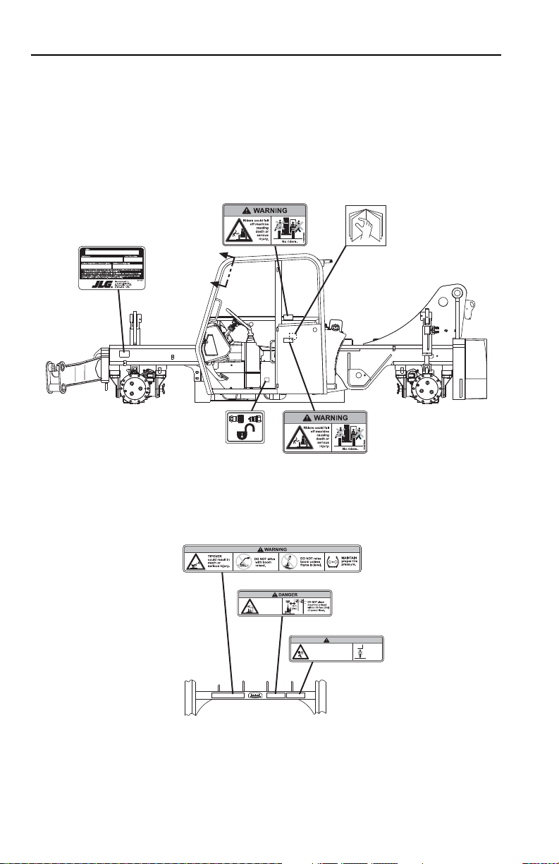
S/N 0160040120 & After, If Equipped
2-6 3126018

OY2650
4109801
4109801
4109801
4109801
1706296
1706304A
RUN-OVER
HAZARD
couldcause
deathor
serious
injury.
1706304
1706767A
1706767
1706851A
1706851
Fasten
seat
belt.
1706303A
Operatormust be trained and
mustread and understand
allcapacity charts, operator
andsafety manuals.
1706303
9
1
1
6
3
0
2
8
R
E
V
.B
F
N
R
91163028
1001121126
1001092897A
10
D
50
L
BF
T
(
N
m
)
50
1001092896A
1001121125
91413061
91413061
1001131745A
1001131745
91563220
9156-3220 REV A
4100181
4100181
DO NOT use Ether or
other high energy
starting aids.
Engine equipped with
Pre-heating system.
ENGINE EXPLOSION
could result in death
or serious injury.
1706300C
1706300
1706301A
1706301
1001109053
2.5 GPM
9.5 lpm
MAX
1001109053 REV A
VIEW B-B VIEW C-C VIEW D-D
B
B
D D
C
C
CAPACITY
CHARTS
Section 2 - Pre-Operation and Inspection
2-73126018
Section 2 - Pre-Operation and Inspection
OY2660
1706302
17063021706302
1706298A
1706298
1706302
1
0
°
1
0
°
0°
1
0
°
1
0
°
2
0
°
2
0
°
3
0
°
3
0
°
4
0
°
4
0
°
5
0
°
5
0
°
6
0
°
6
0
°
7
0
°
7
0
°
8
0
°
8
0
°
1706302
-10
0
10
20
30
40
50
60
7
0
8
0
4105262
17063021706302
91553072
VIEW E-E
E
VIEW F-F
E
FF
2-8 3126018

Section 2 - Pre-Operation and Inspection
OY2670
1706288
1706284
1001092877
91503112
9150-3112 REV -
1705881
1701640
1701640
1001092878
(OPEN CAB)
1001092878
(ENCLOSED CAB)
VIEW A-A
A
A
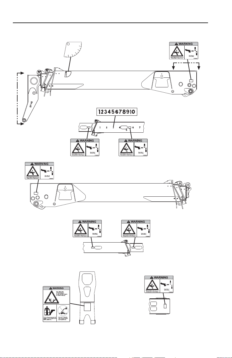
ISO (S/N 0160040120 & After, If Equipped)
2-93126018

Section 2 - Pre-Operation and Inspection
OY2680
4109801
4109801
4109801
4109801
9
1
1
6
3
0
2
8
R
E
V
.B
F
N
R
91163028
1001121126
1001092897A
10
D
50
LB
-F
T
(
N
m
)
50
1001092896
A
1001121125
1706283
1706287
1706289
1706293
91413061
91413061
1001131745A
1001131745
1706281
91563220
9156-3220 REV A
4100181
4100181
1001109053
2.5 GPM
9.5 lpm
MAX
1001109053 REV A
1706098
1706098B
1706285
VIEW B-B VIEW C-C VIEW D-D
B
B
D D
C
C
CAPACITY
CHARTS
2-10 3126018

Section 2 - Pre-Operation and Inspection
OY2690
1706282
1706292 1706292
91553072
1706292
17062921706292
1706292
1
0
°
1
0
°
0°
1
0
°
1
0
°
20°2
0°
3
0
°
3
0
°
4
0
°
4
0
°
5
0
°
5
0
°
6
0
°
6
0
°
7
0
°
7
0
°
8
0
°
8
0
°
-10
0
10
20
30
40
50
60
7
0
8
0
4105262
1706292
VIEW E-E
E
VIEW F-F
E
FF
2-113126018
Section 2 - Pre-Operation and Inspection
OW0322
15
5
5
1
2
3
4
6
7
8
9
10
11
12
13
14
16
17
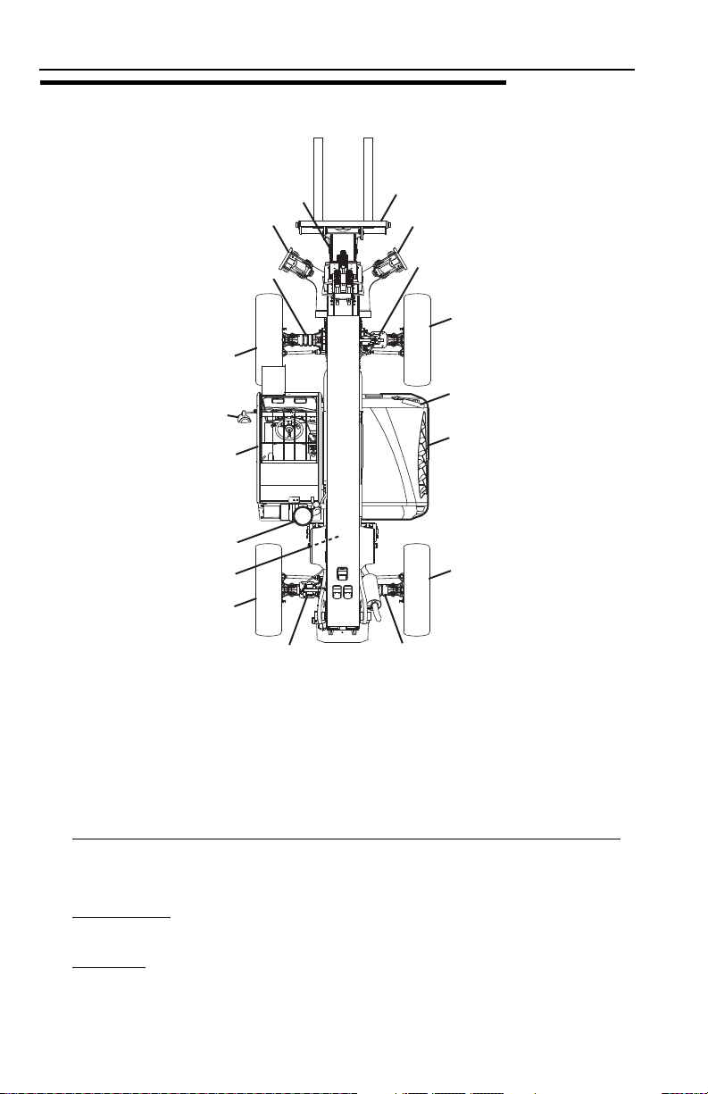
2.3 WALK-AROUND INSPECTION
Begin your walk-around inspection at item 1, as noted below. Continue to your right
(counterclockwise when viewed from top) checking each item in sequence.
INSPECTION NOTE: On all components, make sure there are no loose or missing
parts, that they are securely fastened and no visible leaks or excessive wear exists
in addition to any other criteria mentioned. Inspect all structural members including
attachment for cracks, excessive corrosion and other damage.
1. Boom Sections and Lift, Tilt, Extend/Retract, Compensating (Slave) Cylinders
• Check front, top, side and rear wear pads for presence of grease.
• Pivot pins secure; hydraulic hoses undamaged, not leaking.
2. Left Outrigger
leaking.
3. Front Axle
hydraulic hoses undamaged, not leaking.
2-12 3126018
- Pins secure; hydraulic hoses and cylinder undamaged, not
- Steer cylinders undamaged, not leaking; pivot pins secure;
-

Section 2 - Pre-Operation and Inspection
4. Wheel/Tire Assembly - Properly inflated and secured; no loose or missing lug
nuts. Inspect for worn tread, cuts, tears or other discrepancies.
5. Mirrors
6. Cab and Electrical
7. Air Cleaner
8. Main Control Valve
9. Wheel/Tire Assembly
10. Stabilizer Cylinder
11. Rear Axle
12. Wheel/Tire Assembly
13. Engine Compartment
14. Wheel/Tire Assembly
15. Frame Level Cylinder
16. Right Outrigger
17. Attachment
- Clean and undamaged.
-
• General appearance; no visible damage.
• Frame level indicator and window glass undamaged and clean.
• Gauges, switches, joysticks, foot controls and horn operational.
• Emergency escape hammer in place (enclosed cab only).
• Check seat belt for damage, replace belt if frayed or cut webbing, damaged
buckles or loose mounting hardware.
(Before S/N 0160039451 excluding 0160039394 & 0160039397) Air cleaner element condition indicator, check for clogged condition. Replace
element as required.
- See Inspection Note.
- Properly inflated and secured; no loose or missing lug
nuts. Inspect for worn tread, cuts, tears or other discrepancies.
- Pins secure; hydraulic hoses undamaged, not leaking.
- Steer cylinders undamaged, not leaking; pivot pins secure;
hydraulic hoses undamaged, not leaking.
- Properly inflated and secured; no loose or missing lug
nuts. Inspect for worn tread, cuts, tears or other discrepancies.
-
• Drive belts, check condition and replace as required.
• Engine mounts - See inspection note.
• Air cleaner element condition indicator (S/N 0160039451 & After including
0160039394 & 0160039397), check for clogged condition. Replace element
as required.
• Battery cables tight, no visible damage or corrosion.
• Engine cover properly secured.
- Properly inflated and secured; no loose or missing lug
nuts. Inspect for worn tread, cuts, tears or other discrepancies.
- Pins secure; hydraulic hoses undamaged, not leaking.
- Pins secure; hydraulic hoses and cylinder undamaged, not
leaking.
- Properly installed, see See “Attachment Installation” on
page 5-13.
2-133126018

Section 2 - Pre-Operation and Inspection
2.4 WARM-UP AND OPERATIONAL CHECKS
Warm-Up Check
During warm-up period, check:
1. Heater, defroster and windshield wiper (if equipped).
2. Check all lighting systems (if equipped) for proper operation.
3. Voltmeter should show 13.5 to 14 volts.
4. Adjust mirror(s) for maximum visibility.
WARNING
CUT/CRUSH/BURN HAZARD. Keep engine cover closed while engine is
running except when checking transmission oil level and hydraulic filter condition
indicator.
Operational Check
When engine warms, perform an operational check:
1. Service brake and parking brake operation.
2. Forward and reverse travel.
3. Each gear.
4. Steering in both directions with engine at low idle (steering lock to lock will not
be reached). Check in each steering mode.
5. Horn and back-up alarm. Must be audible from inside operators cab with engine
running.
6. All joystick functions - operate smoothly and correctly.
7. Perform any additional checks described in Section 8.
8. Hydraulic filter condition indicator.
2-14 3126018

Section 2 - Pre-Operation and Inspection
2.5 OPERATOR CAB
The telehandler is equipped with an open or enclosed ROPS/FOPS cab.
WARNING
Never operate telehandler unless the overhead guard, cab structure and right
side glass or screen are in good condition. Any modification to this machine must
be approved by JLG to assure compliance with ROPS/FOPS certification for this
cab/machine configuration. If the overhead guard or cab structure is damaged,
the CAB CANNOT BE REPAIRED. It must be REPLACED.
2-153126018

Section 2 - Pre-Operation and Inspection
OAL0011
1
2
3
4
2.6 WINDOWS
Keep all windows and mirrors clean and unobstructed.
Cab Door Window (if equipped)
• Cab door (1) must be closed during operation.
• During operation the cab door window (2) must either be latched open or closed.
• Open the cab door window and secure it in the latch (3).
• Press latch release button inside the cab or pull on lever (4) outside the cab to
unlatch the window.
2-16 3126018

Section 3 - Controls and Indicators
SECTION 3 - CONTROLS AND INDICATORS
3.1 GENERAL
This section provides the necessary information needed to understand control
functions.
Note: The manufacturer has no direct control over machine application and
operation. The user and operator are responsible for conforming with good safety
practices.
NOTICE
EQUIPMENT DAMAGE. When a red light illuminates (except park brake),
immediately bring machine to a stop, lower boom and attachment to ground and
stop the engine. Determine cause and correct before continued use.
3-13126018

Section 3 - Controls and Indicators
OW0363
8
11
5
1
4
2
3
6
7
9
10
12
13
14
3.2 CONTROLS
1. Transmission Control Lever: See page 3-8.
2. Instrument Panel
3. Steering Wheel
machine in the corresponding direction. Three steering modes are available.
See “Steer Modes” on page 3-16.
4. Frame Level Indicato
condition of the telehandler.
5. Accessory Control Lever
6. Right Hand Panel
7. Boom Joystick
8. Frame Level Joystick
9. Auxiliary Hydraulic Joystick
10. Outrigger Joysticks
3-2 3126018
: See page 3-4.
: Turning the steering wheel to the left or right steers the
r: Enables the operator to determine the left to right level
: See page 3-14.
: See page 3-10.
: See page 3-11.
: See page 3-13.
(if equipped): See page 3-15.
(if equipped): See page 3-12.

Section 3 - Controls and Indicators
11. Decompression Valve: Depress button to relieve pressure in auxiliary hydraulic
circuit.
12. Accelerator Pedal
speed.
13. Service Brake Pedal
speed.
14. Ignition Switch
: Pressing down the pedal increases engine and hydraulic
: Key activated. See page 3-6.
: The further the pedal is depressed, the slower the travel
3-33126018
Section 3 - Controls and Indicators
OW0433
8910
12
11
7
64
432
1
4
12 35
8910
11
64
12
8910
11
7
8910
12
11
7
64
432
1
PERKINS
(BEFORE S/N 0160037186)
JOHN DEERE
PERKINS
(S/N 0160037186 THRU 0160039451
EXCLUDING 0160039394 & 0160039397)
CUMMINS
(S/N 0160039451 & AFTER INCLUDING
0160039394 & 0160039397)
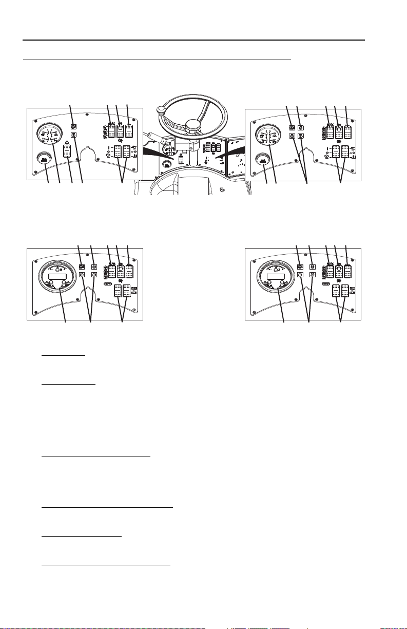
Dash Controls and Indicators
1. Hourmeter: Indicates total time of engine operation in hours and tenths of
hours.
2. 4-in-1 Gauge
a. Engine Coolant Temperature Gauge
:
b. Engine Oil Pressure Gauge
c. Fuel Gauge
d. Voltmeter indicates alternator output and battery condition.
3. Shutdown Override Switch
(John Deere Only): Delays engine shutdown for 30
seconds when depressed. The switch resets the shutdown timer to 30 seconds
and may be used repeatedly. However, continuously holding the switch will not
reset the 30 second timer.
4. Transmission Temperature Light: Illuminates when transmission temperature is
too high.
5. Check Engine Light
(John Deere Only): Illuminates for 30 seconds before
engine shuts down when a “Shutdown” fault is detected.
6. Engine Pre-Heat Indicator Light
ignition key in the “RUN” position. Light goes out when start temperature is
reached. At temperatures below 32°F (0°C), do not start until light goes out.
(Perkins and Cummins Only): Illuminates with
3-4 3126018

Section 3 - Controls and Indicators
7. Warning and Check Engine Lights (Perkins and Cummins Only): Any
combination of illumination indicates an engine fault and/or a parameter that is
outside of acceptable range. Engine may derate or shutdown.
8. Steer Select Switch
and 2-wheel steer. See page 3-16 for details.
: Three positions: 4-wheel circle steer, 4-wheel crab steer
9. Park Brake Switch
10. Horn Button
11. Auxiliary Electrics Switches
require auxiliary electrics. See Section 5 - Attachments for approved
attachments and control instructions.
12. 3-in-1 Gauge & Display
excluding 0160039394 & 0160039397):
a. Engine Coolant Temperature Gauge
b. Engine Oil Pressure Gauge
c. Fuel Gauge
d. Display - Displays engine operating hours, battery voltage and engine rpm.
Engine fault codes displayed when detected. See Service Manual for
details.
: See page 3-7 for details.
: Depress button to sound horn.
(if equipped): Enables functions of attachments that
(Cummins) (Perkins S/N 0160037186 thru 0160039451
3-53126018

Section 3 - Controls and Indicators
OW0391
ACC
RUN
START
OFF
9141-3061
Ignition
• In "ACC" or "RUN" position, voltage is available for all electrical functions.
• Full clockwise rotation to "START" engages starter motor.
• Counter-clockwise rotation to "OFF" stops engine and removes voltage from all
electrical functions.
3-6 3126018

Section 3 - Controls and Indicators
OAL0471
2
1
Park Brake
Park brake switch controls the application and release of the park brake. Indicator
light on switch illuminates to indicate brake is applied.
• With the engine running and the park brake switch in "OFF" position (1), park
brakes are disengaged.
• With switch in "ON" position (2), park brake is engaged and transmission will not
engage forward or reverse.
WARNING
MACHINE ROLL-AWAY HAZARD. Always move park brake switch to "ON"
position, lower boom to ground and stop engine before leaving cab.
WARNING
CRUSH HAZARD. Turning engine off applies the park brake. Applying park
brake or turning engine off while traveling will cause unit to stop abruptly and
could cause load loss. Either may be used in an emergency situation.
Parking Procedure
1. Using service brake, stop telehandler in an appropriate parking area.
2. Follow “Shut-Down Procedure” on page 4-5.
3-73126018
Section 3 - Controls and Indicators
OAL0481
N
F
R
1
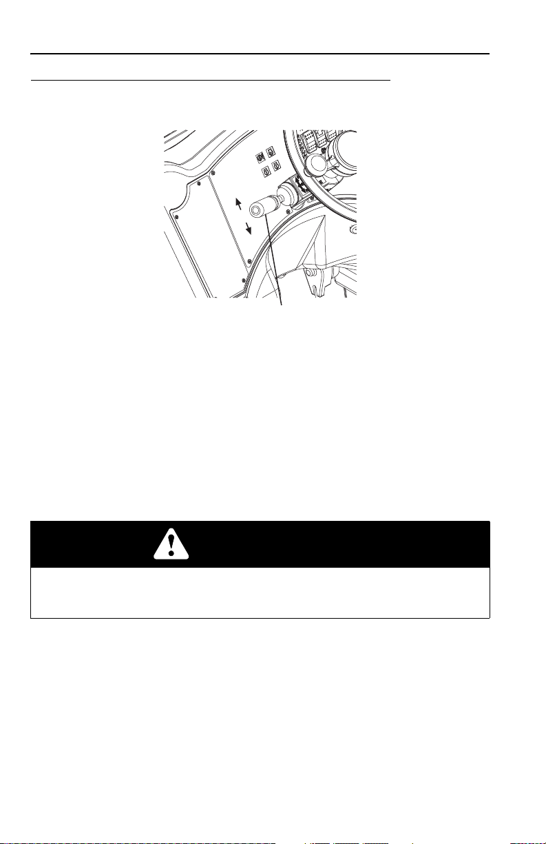
Transmission Control Lever
Direction of Travel Selection
Transmission control lever (1) engages forward or reverse travel.
• Lift and push lever forward for forward travel; lift and pull lever rearward for
reverse travel. Move lever to centered position for neutral.
• Forward or reverse travel can be selected while in any gear.
• When traveling in reverse, the back-up alarm will automatically sound.
• Drive in reverse and turn only at slow rates of speed.
• Do not increase engine speed with the transmission in forward or reverse and
the service brake depressed in an attempt to get quicker hydraulic performances.
This could cause unexpected machine movement.
WARNING
TIP OVER/CRUSH HAZARD. Bring telehandler to a complete stop before
shifting transmission control lever. A sudden change in direction of travel could
reduce stability and/or cause load to shift or fall.
3-8 3126018

Section 3 - Controls and Indicators
OAL0491
1st
2nd
3rd
4th
2
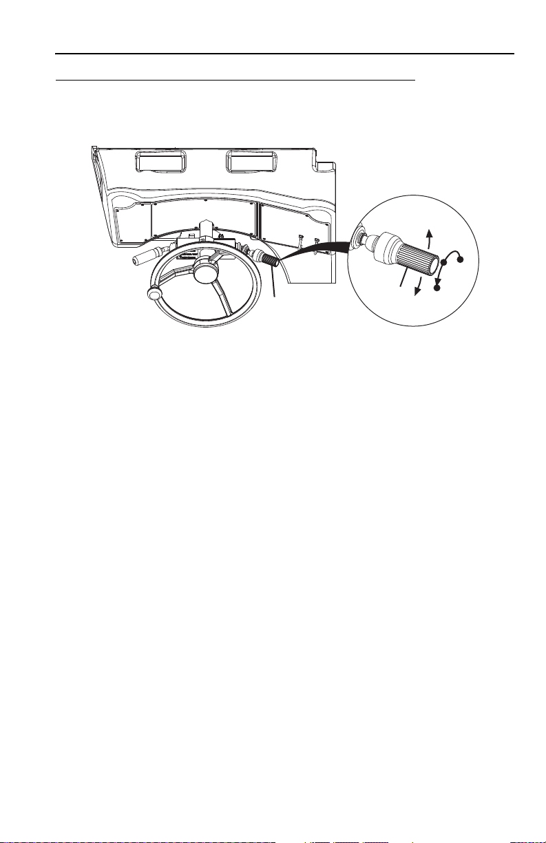
Gear Selection
Gear selection is located on the twist grip handle (2) of transmission control lever.
• Twist hand grip to select gear.
• Select the appropriate gear for the task being performed. Use a lower gear
when transporting a load. Use a higher gear only when driving unloaded for
longer distances.
• Slow down prior to downshifting. Do not downshift more than one gear at a
time.
3-93126018

Section 3 - Controls and Indicators
OAL0500
1
3
2
Boom Joystick
The boom joystick (1) controls the boom and attachment tilt functions.
Boom Functions
• Move the joystick back to lift boom; move joystick forward to lower boom; move
joystick right to extend boom; move joystick left to retract boom.
• The speed of boom functions depends upon the amount of joystick travel in
corresponding direction. Increasing engine speed will also increase function
speed.
• For two simultaneous boom functions, move the joystick between quadrants. For
example; moving the joystick forward and to the left will lower and retract boom
simultaneously.
Attachment Function
Tilt control is actuated by the switch (2).
• Depress the left side of the switch to tilt up; depress the right side of switch to tilt
down.
• Use rotary switch (3) to regulate the speed of the tilt. Rotate knob counterclockwise to increase speed; rotate knob clockwise to decrease speed.
WARNING
TIP OVER/CRUSH HAZARD. Rapid, jerky operation of controls will cause rapid,
jerky movement of the load. Such movements could cause the load to shift or fall
or could cause the machine to tip over.
3-10 3126018

Section 3 - Controls and Indicators
OAL0510
4
Frame Level Joystick
The frame level joystick (4) controls the left to right frame level.
• Move the joystick left to rotate frame left, move the joystick right to rotate frame
right.
• A level indicator is located above the front cab window to permit operator to
determine whether the telehandler frame is level.
WARNING
TIP OVER HAZARD. Always move boom as low as possible while allowing for
best visibility of right hand mirror before leveling frame. Attempting to level
machine with boom raised could cause it to tip over.
3-113126018

Section 3 - Controls and Indicators
OW0521
1
Auxiliary Hydraulic Joystick (if equipped)
The auxiliary hydraulic joystick (1) controls function of attachments that require
hydraulic supply for operation. See Section 5 - Attachments for approved
attachments and control instructions.
3-12 3126018

Section 3 - Controls and Indicators
OAL0530
2
Outrigger Joysticks
The rear joysticks (2) control the outriggers.
• The left joystick controls the left outrigger and the right joystick controls the right
outrigger.
• Push joysticks forward to lower outriggers; push joysticks back to raise
outriggers.
• Use outriggers to increase stability and/or load capacity and in leveling the
telehandler. Study capacity charts to determine maximum load capacities, with
and without outriggers.
WARNING
TIP OVER HAZARD. Outriggers increase stability and load capacity only if they
are used properly. Using outriggers on soft surfaces could cause telehandler to
tip over. Always ensure surface can support telehandler and load.
3-133126018

Section 3 - Controls and Indicators
OAL0541
2
1
1
2
10
11
6
5
4
12
13
9
2
3
8
7
Right Hand Panel
Heater and Air Conditioning Controls (if equipped)
1. Air Vent
2. Air Louver
3. Defroster Fan
switch up for fast speed. Return switch to middle position to turn off.
4. Temperature Control Switch
5. Fan Speed
6. Air Conditioning Switch
7. Air Louver
8. Recirculation Vent
heat. Close louvers when operating air conditioning.
Other Controls (if equipped)
9. Work Light Switch
10. Beacon Light Switch
11. Hazard Light Switch
12. Windshield Wiper and Washer Switch
activate washer. Return to first position to turn off wiper.
13. Attachment Tilt Speed Switch
: Two individually adjustable round vents.
: Three individually adjustable air louvers.
: Two speed fan. Press fan switch down for slow speed; press
: Adjustable rotary switch
: Four-position rotary switch.
: On/Off switch.
(S/N 0160038377 & After): Two individually adjustable air louvers.
(S/N 0160038377 & After): Open louvers when operating
: On/Off switch.
: On/Off switch.
: On/Off switch.
: Two speed rotary switch. Depress to
: See “Boom Joystick” on page 3-10.
3-14 3126018
Section 3 - Controls and Indicators
OY1350
2
3
7
5
6
4
1
Accessory Control Lever (if equipped)
The accessory control lever (1) operates the turn signals, parking lights and
headlights.
Tur n S ignals
• Push the lever forward (2) to activate the left turn signal.
• Pull the lever back (3) to activate the right turn signal.
• The lever must be manually returned to the center position to deactivate either
turn signal. The lever will not cancel automatically after a turn.
Parking Lights and Headlights
• Turn the twist grip (4) of the lever counterclockwise to the first position (5) to turn
on the parking lights.
• Turn the twist grip to the second position (6) to turn on the headlights.
• Raise/lower the lever to switch between low and high beam.
• Turn the twist grip clockwise to the OFF position (7) to turn all lights off.
3-153126018
Section 3 - Controls and Indicators
OAL2030
2-Wheel Front Steer 4-Wheel Circle Steer 4-Wheel Crab Steer
OY1490
123
OAM2400
4 5
3.3 STEER MODES
Three steer modes are available for operator use.
Note: 2-Wheel Front Steer mode is required for travel on public roads.
Steer Mode Change
1. Bring machine to a stop using service brake while either circle steer mode (1) or
crab steer mode (3) is selected.
2. Turn the steering wheel until the left rear wheel (4) is aligned with the side of the
machine.
3. Select front steer mode (2).
4. Turn the steering wheel until the left front wheel (5) is aligned with the side of
the machine.
5. Wheels are now aligned. Select desired steer mode.
3-16 3126018

Section 3 - Controls and Indicators
1
2
3
4
OW0480
3.4 OPERATOR SEAT
Adjustments
Prior to starting engine adjust seat for position and comfort.
1. Suspension: Use knob to adjust suspension to the appropriate setting. Turn
clockwise to increase stiffness. Turn counterclockwise to reduce stiffness.
2. Fore/Aft
3. Arm Rest
: Pull up on handle to move seat fore and aft.
: Arm rest can be moved up or down for comfort.
4. Seat Belt
seat belt is available.
: Always fasten seat belt during operation. If required, a 3 in (76 mm)
3-173126018

Section 3 - Controls and Indicators
OH20912
Seat Belt
Fasten seat belt as follows:
1. Grasp both free ends of the belt making certain that belt webbing is not twisted
or entangled.
2. With back straight in the seat, couple the retractable end (male end) of the belt
into the receptacle (buckle) end of the belt.
3. With belt buckle positioned as low on the body as possible, pull the retractable
end of the belt away from the buckle until it is tight across the lap.
4. To release belt latch, depress red button on the buckle and pull free end from
buckle.
3-18 3126018

Section 3 - Controls and Indicators
OW1220
1
2
-10
10
20
30
40
50
6
0
70
80
3.5 BOOM ANGLE AND EXTENSION INDICATORS
• The boom angle indicator (1) is located on the left side of the boom. Use this
indicator to determine the boom angle when using the capacity chart (see “Use
of the Capacity Chart” on page 5-7).
• The boom extension indicators (2) are located on the left side of the boom. Use
these indicators to determine boom extension when using the capacity chart (see
“Use of the Capacity Chart” on page 5-7).
3-193126018

Section 3 - Controls and Indicators
This Page Intentionally Left Blank
3-20 3126018

Section 4 - Operation
SECTION 4 - OPERATION
4.1 ENGINE
Starting the Engine
This machine can be operated under normal conditions in temperatures of 0°F to
104°F (-20°C to 40°C). Consult JLG for operation outside this range or under
abnormal conditions.
If equipped for extreme cold weather, -40°F to 0°F (-40°C to -20°C), see page 4-3
for starting procedure.
1. Make sure all controls are in “Neutral” and all electrical components (lights,
heater, defroster, etc.) are turned off. Apply parking brake.
2. If equipped with Perkins or Cummins engine and the temperature is below 32°F
(0°C), turn the ignition switch to “RUN”. Wait until the preheat indicator light
goes out.
3. Turn ignition switch to “START” to engage starting motor. Release key
immediately when engine starts. If engine fails to start within 20 seconds,
release key and allow starting motor to cool for a few minutes before trying
again.
4. After engine starts, observe oil pressure gauge. If gauge remains on zero for
more than ten seconds, stop engine and determine cause before restarting
engine. Reference engine manual for minimum pressure at operating
temperature.
5. Warm up engine at approximately 1/2 throttle.
Note: Engine will not start unless transmission control lever is in “Neutral” and park
brake switch is applied.
WARNING
UNEXPECTED MOVEMENT HAZARD. Always ensure that transmission control
lever is in neutral and the service brake is applied before releasing park brake.
Releasing park brake in either forward or reverse could cause the machine to
move abruptly.
4-13126018

Section 4 - Operation
Cold Weather Starting Aids
John Deere Engine
JLG approved starting aids employ ether. If your telehandler is equipped with an
ether starting aid, the following applies:
• Injection of ether is triggered by temperature sensor located on engine.
• At start-up, temperature sensor on engine will detect if ether is needed. Follow
normal start-up procedure.
• Ether will be automatically injected if needed, to keep engine running.
• A second battery is added for additional cold-cranking capacity.
WARNING
ENGINE EXPLOSION. If your telehandler is equipped with a cold start aid, do not
spray additional ether into air cleaner. If machine is not equipped with cold start
aid, follow instructions listed in the engine manual supplied with the telehandler.
Perkins or Cummins Engine
Perkins and Cummins engines are equipped with preheat for cold weather starting.
Refer to “Starting the Engine” on page 4-1 for cold weather starting procedure.
WARNING
ENGINE EXPLOSION. Do not use ether for cold weather starting.
4-2 3126018

Section 4 - Operation
OY1971
3
1
1
2
Extreme Cold Weather Starting (if equipped)
If equipped with extreme cold weather components, machine can be operated in
temperatures of -40°F to 0°F (-40° C to -20° C).
1. Machine must be equipped with heating components and extreme cold weather
fluids. See Section 9 - Specifications for fluid details.
2. Locate two yellow heating component extension cords stored behind batteries
in engine compartment. Connect each to separate A/C power supplies with a
minimum rating of 15 Amps each.
3. Allow heating components to operate a minimum of 12 hours prior to machine
operation.
4. Locate recirculation hoses stored behind seat in cab.
5. Connect recirculation hose (1) to tilt circuit quick disconnects (2). Connect the
other recirculation hose (1) to auxiliary hydraulic quick disconnects (3).
6. Follow start-up procedure on page 4-1 and allow engine to idle 20 minutes.
7. Operate tilt and auxiliary hydraulic functions continuously for five minutes to
circulate the warm hydraulic fluid.
8. Operate all boom functions continuously for another five minutes.
9. Perform “Shut-Down Procedure” on page 4-5.
10. Disconnect recirculation hoses and A/C power supplies and place back in
storage locations.
11. Machine is ready for operation.
4-33126018
Section 4 - Operation
OW0530
Battery Boosted Starting
If battery-boost starting (jump-start) is necessary, proceed as follows:
• Never allow vehicles to touch.
• Ensure boosting vehicle engine is running.
• Connect the positive (+) jumper cable to positive (+) post of discharged battery.
• Connect the opposite end of positive (+) jumper cable to positive (+) post of
booster battery.
• Connect the negative (-) jumper cable to negative (-) post on booster battery.
• Connect opposite end of negative (-) jumper cable to ground point on machine
away from discharged battery.
• Follow standard starting procedures.
• Remove cables in reverse order after machine has started.
WARNING
BATTERY EXPLOSION HAZARD. Never jump start or charge a frozen battery
as it could explode. Keep sparks, flames and lighted smoking materials away
from the battery. Lead acid batteries generate explosive gases when charging.
Wear safety glasses.
4-4 3126018

Section 4 - Operation
Normal Engine Operation
• Observe instrument panel frequently to be sure all systems are functioning
properly.
• Be alert for unusual noises or vibration. When an unusual condition is
noticed, park machine in safe position and perform shut-down procedure. Report
condition to your supervisor or maintenance personnel.
• Avoid prolonged idling. If the engine is not being used, turn it off.
Shut-Down Procedure
When parking the telehandler, park in a safe location on flat level ground and away
from other equipment and/or traffic lanes.
1. Apply the park brake.
2. Shift the transmission to “Neutral.”
3. Lower forks or attachment to the ground.
4. Operate engine at low idle for 3 to 5 minutes. DO NOT over rev engine.
5. Shut off engine and remove ignition key.
6. Exit telehandler properly.
7. Block wheels (if necessary).
4-53126018

Section 4 - Operation
4.2 OPERATING WITH A NON-SUSPENDED LOAD
Lift Load Safely
• You must know the weight and load center of every load you lift. If you are not
sure of the weight and load center, check with your supervisor or with the
supplier of the material.
WARNING
TIP OVER HAZARD. Exceeding lift capacity of the telehandler could damage the
equipment and/or cause tip over.
• Know the rated load capacities (see Section 5) of the telehandler to determine
the operating range in which you can safely lift, transport and place a load.
Picking Up a Load
• Note the conditions of the terrain. Adjust travel speed and reduce amount of load
if conditions warrant.
• Avoid lifting double-tiered loads.
• Make sure load is clear of any adjacent obstacles.
• Adjust spacing of forks so they engage the pallet or load at maximum width. See
“Adjusting/Moving Forks” on page 5-17.
• Approach load slowly and squarely with fork tips straight and level. NEVER
attempt to lift a load with just one fork.
• NEVER operate telehandler without a proper and legible capacity chart in the
operator cab for the telehandler/attachment combination you are using.
4-6 3126018

Section 4 - Operation
OW0540
Transporting a Load
After engaging the load and resting it against the backrest, tilt the load back to
position it for travel. Travel in accordance with the requirements set forth in Section
1 - General Safety Practices and Section 5 - Attachments.
Leveling Procedure
1. Position machine in best location to lift or place load.
2. Apply parking brake and move transmission control lever to NEUTRAL.
3. Observe level indicator to determine whether machine must be leveled prior to
lifting load. Level machine with frame level joystick (see page 3-11) or outrigger
joysticks (see page 3-13).
4. Move boom/attachment to 4 ft (1,2 m) off ground.
(AUS - Move boom so forks are no more than 11.8 in (300 mm) above ground
surface.)
Important things to remember:
• Never raise the boom/attachment more than 4 ft (1,2 m) above ground unless
telehandler is level.
(AUS - Never raise the forks more than 11.8 in (300 mm) above ground surface
unless telehandler is level.)
• The combination of frame leveling and load could cause the telehandler to tip
over.
4-73126018

Section 4 - Operation
Placing a Load
Before placing any load be sure that:
• The landing point can safely support the weight of the load.
• The landing point is level; front to back and side to side.
• Use the capacity chart to determine safe boom extension range. See “Use of the
Capacity Chart” on page 5-7.
• Align forks at the level load is to be placed, then extend boom slowly until load is
just above area where it is to be placed.
• Lower the boom until the load rests in position and the forks are free to retract.
Disengaging a Load
Once the load has been placed safely at the landing point, proceed as follows:
1. With the forks free from the weight of the load, the boom can be retracted
and/or the telehandler can be backed away from under the load if surface will
not change level condition of telehandler.
2. Lower the carriage.
3. The telehandler can now be driven from the landing location to continue work.
4-8 3126018

Section 4 - Operation
4.3 OPERATING WITH A SUSPENDED LOAD
Lift Load Safely
• You must know the weight and load center of every load you lift. If you are not
sure of the weight and load center, check with your supervisor or with the
supplier of the material.
WARNING
TIP OVER HAZARD. Exceeding lift capacity of the telehandler could damage the
equipment and/or cause tip over.
• Know the rated load capacities (refer to Section 5) of the telehandler to
determine the operating range in which you can safely lift, transport and place a
load.
Picking Up a Suspended Load
• Note the conditions of the terrain. Adjust travel speed and reduce amount of load
if conditions warrant.
• Avoid lifting double-tiered loads.
• Make sure load is clear of any adjacent obstacles.
• NEVER operate telehandler without a proper and legible capacity chart in the
operator cab for the telehandler/attachment combination you are using.
• Only use approved lifting devices rated for the lifting of the load.
• Identify the proper lifting points of the load, taking into consideration the center of
gravity and load stability.
• Ensure to always properly tether loads to restrict movement.
• Refer to See “Use of the Capacity Chart” on page 5-7. for proper lifting guidelines
in addition to the appropriate capacity chart in the operator cab.
4-93126018

Section 4 - Operation
OW0130
OZ3160
Transporting a Suspended Load
• Travel in accordance with the requirements set forth in Section 1 - General
Safety Practices and Section 5 - Attachments.
• For additional requirements, refer to the appropriate capacity chart in the
operator cab.
Important things to remember:
• Ensure the boom is fully retracted.
• Never raise the load more than 11.8 in (300 mm) above ground surface or the
boom more than 45°.
• The combination of frame leveling and load could cause the telehandler to tip
over.
• The guide persons and operator must remain in constant communication (verbal
or hand) and be in visual contact with the operator at all times.
• Never place the guide persons between the suspended load and the telehandler.
• Only transport the load at walking speed, 0.9 mph (0,4 m/s), or less.
Leveling Procedure
1. Position machine in best location to lift or place load.
2. Apply parking brake and move transmission control lever to NEUTRAL.
3. Observe level indicator to determine whether machine must be leveled prior to
lifting load. Level machine with frame level joystick (see page 3-11) or outrigger
joysticks (see page 3-13).
4. Move boom so load is no more than 11.8 in (300 mm) above ground surface
and boom/or boom is raised no more than 45°.
4-10 3126018

Section 4 - Operation
Placing a Suspended Load
Before placing any load be sure that:
• The landing point can safely support the weight of the load.
• The landing point is level; front to back and side to side.
• Use the capacity chart to determine safe boom extension range. See “Use of the
Capacity Chart” on page 5-7.
• Align load at the level load is to be placed, then position boom slowly until load is
just above area where it is to be placed.
• Ensure that the guide persons and operator remain in constant communication
(verbal or hand) when placing the load.
Disengaging a Suspended Load
• Never place the guide persons between the suspended load and the telehandler.
• Once at the destination of the load, ensure to bring the telehandler to a complete
stop and apply the park brake prior to disengagement of the lifting devices and
tethers.
4-113126018

Section 4 - Operation
OAL0591
4.4 LOADING AND SECURING FOR TRANSPORT
Tiedown
1. Level the telehandler prior to loading.
2. Using a spotter, load the telehandler with boom as low as possible.
3. Once loaded, apply parking brake and lower boom until boom or attachment is
resting on deck. Move all controls to “Neutral,” stop engine and remove ignition
key.
4. Secure machine to deck by passing chains through the designated tie down
points as shown in the figure.
5. Do not tie down front of boom.
Note: The user assumes all responsibility for choosing the proper method of
transportation and tie-down devices, making sure the equipment used is capable of
supporting the weight of the vehicle being transported and that all manufacturer’s
instructions and warnings, regulations and safety rules of their employer, the
Department of Transportation and/or any other local, state or federal/provincial laws
are followed.
WARNING
TELEHANDLER SLIDE HAZARD. Before loading telehandler for transport,
make sure deck, ramps and telehandler wheels are free of mud, snow and ice.
Failure to do so could cause telehandler to slide.
4-12 3126018

Section 4 - Operation
Lifting
• When lifting machine, it is very important that the lifting device and equipment is
attached only to designated lifting points. If machine is not equipped with lifting
lugs contact JLG Product Safety for information.
• Make adjustments to the lifting device and equipment to ensure the machine will
be level when elevated. The machine must remain level at all times while being
lifted.
• Ensure that the lifting device and equipment is adequately rated and suitable for
the intended purpose. See Section 9 - Specifications for machine weight.
• Remove all loose items from machine prior to lifting.
• Lift machine with smooth, even motion. Set machine down gently. Avoid quick or
sudden motions that could cause shock loads to machine and/or lifting devices.
4-133126018

Section 4 - Operation
This Page Intentionally Left Blank
4-14 3126018

Section 5 - Attachments
SECTION 5 - ATTACHMENTS
5.1 APPROVED ATTACHMENTS
To determine if an attachment is approved for use on the specific telehandler you
are using, perform the following prior to installation.
Before S/N 0160037689
• The attachment model/option number on the attachment identification plate must
match the attachment number on a capacity chart located in the operator cab.
• The model on the capacity chart must match the model telehandler being used.
• The load center of the fork (if equipped) must match the load center as indicated
on the capacity chart.
• Hydraulically powered attachments must only be used on machines equipped
with auxiliary hydraulics.
• Hydraulically powered attachments that require auxiliary electrics must only be
used on machines equipped with auxiliary hydraulics and electrics.
S/N 0160037689 & After
• The attachment type, weight, dimensions and load center must be equal to or
less than the data shown on a capacity chart located in the operator cab.
• The model on the capacity chart must match the model telehandler being used.
• Hydraulically powered attachments must only be used on machines equipped
with auxiliary hydraulics.
• Hydraulically powered attachments that require auxiliary electrics must only be
used on machines equipped with auxiliary hydraulics and electrics.
If any of the above conditions are not met, do not use the attachment. The
telehandler may not be equipped with the proper capacity chart or the attachment
may not be approved for the model telehandler being used. Contact JLG or a local
distributor for further information.
5-13126018

Section 5 - Attachments
5.2 UNAPPROVED ATTACHMENTS
Do not use unapproved attachments for the following reasons:
• Range and capacity limitations for “will fit,” homemade, altered, or other
non-approved attachments cannot be established.
• An overextended or overloaded telehandler can tip over with little or no warning
and cause serious injury or death to the operator and/or those working nearby.
• The ability of a non-approved attachment to perform its intended function safely
cannot be assured.
WARNING
Use only approved attachments. Attachments which have not been approved for
use with your telehandler could cause machine damage or an accident.
5-2 3126018

5.3 JLG SUPPLIED ATTACHMENTS
Before S/N 0160037689
Section 5 - Attachments
Attachment Part Number
Carriage, 48 in (1220 mm) 91405073 X X
Carriage, 50 in (1270 mm) 1170019 X X
Carriage, 60 in (1524 mm) 1170022 X X
Carriage, 72 in (1829 mm) 91405074 X X
Carriage, 72 in (1829 mm) 1170025 X X
Carriage, Drywall 72 in (1829 mm) 91405077 X X
Side Tilt Carriage, 48 in (1220 mm) 91405101 X X
Side Tilt Carriage, 72 in (1829 mm) 91405079 X X
100° Swing Carriage, 72 in (1829 mm) 91405075 X X
100° Drywall Swing Carriage, 72 in (1829 mm) 91405078 X X
180° Swing Carriage, 72 in (1829 mm) 91563146 X X
6 ft Mast Carriage, 48 in (1220 mm) 91405060 X X
6 ft Mast Carriage, 72 in (1829 mm) 91405061 X X
6 ft Mast Carriage, 100°, 72 in (1829 mm) 91405070 X X
Fork, Pallet 1.75x4x48 in (44x101x1220 mm) 91403364 X X
6 ft Mast Carriage, 100°, 60 in (1524 mm) 91415026 X X
Fork, Pallet 2x6x60 in (50x152x1524 mm) 91403580 X X
8 ft Mast Carriage with Side Tilt, 72 in (1830 mm) 1001108669 X X
Fork, Pallet 2.25x4x48 in (57x101x1220 mm) 91513206 X X
Fork, Pallet 2.36x4x48 in (60x101x1220 mm) 2340045 X X
Fork, Pallet 2.25x5x48 in (57x127x1220 mm) 91563141 X X
Fork, Pallet 2.36x5x48 in (60x127x1220 mm) 2340038 X X
Fork, Pallet 2x6x48 in (50x152x1220 mm) 91403363 X X
Fork, Pallet 2x6x60 in (50x152x1524 mm) 91403360 X X
Fork, Pallet 2x6x60 in (50x152x1524 mm) 91403365 X X
Fork, Lumber 2.25x6x60 in (57x152x1524 mm) 91563142 X X
Fork, Dual Taper 1.75x7x60 in (44x178x1524 mm) 2340046 X X
Fork, Dual Taper 2.36x6x60 in (60x152x1524 mm) 2340039 X X
Fork, Dual Taper 2x6x72 in (50x152x1830 mm) 1001092391 X X
Fork, Lumber 2.25x6x72 in (57x152x1830 mm) 91563143 X X
Fork, Cubing 2x2x48 in (50x50x1220 mm) 91403359 X X
Fork, Block 2x2x48 in (50x50x1220 mm) 2340037 X X
Fork, Drywall 1.75x4x48 in (50x101x1220 mm) 91403366 X X
Bucket, 60 in - 0.75 yd
Bucket, 74 in - 1.25 yd
Bucket, 102 in -1.25 yd
3
3
3
91405054 X X
91405055 X X
91405071 X X
Applicable Model
G10-55A G12-55A
5-33126018

Section 5 - Attachments
Attachment Part Number
Grapple Bucket, 96 in -1.75 yd
Hook, Fork Mounted 90553036 X X
Hook, Fork Mounted 91565094 X X
Truss Boom, 10 ft (3048 mm) 91405083 X X
Truss Boom w/ Winch, 10 ft (3048 mm) 91405081 X X
Truss Boom, 15 ft (4572 mm) 91405082 X X
Truss Boom w/ Winch, 15 ft (4572 mm) 91405080 X X
Winch, Boom Head-Mounted
Platform, Quick Switch Mounted 91415025 X X
Platform, Fork Mounted (ASME)
Platform, Fork Mounted (ASME - French)
Platform, Fork Mounted (ISO)
3
0930021 X X
91565037 X X
1001097944 X X
1001092280 X X
1001103637 X X
1001097072 X X
1001103736 X X
1001096306 X X
1001103730 X X
Applicable Model
G10-55A G12-55A
5-4 3126018

S/N 0160037689 & After
Section 5 - Attachments
Attachment Part Number
Carriage, 50 in (1270 mm) 1170021 X X
Carriage, 60 in (1524 mm) 1170024 X X
Carriage, 72 in (1829 mm)
Side Tilt Carriage, 50 in (1270 mm) 1170054 X X
Side Tilt Carriage, 60 in (1524 mm) 1001101956 X X
Side Tilt Carriage, 72 in (1829 mm) 1170057 X X
90° Swing Carriage, 72 in (1829 mm) 1001095418 X X
180° Swing Carriage, 72 in (1829 mm) 1001104992 X X
Dual Fork Positioning Carriage, 50 in (1270 mm) 7301295 X X
8 ft Mast Carriage, 50 in (1270 mm) 1001108668 X X
8 ft Mast Carriage w/ Side Tilt, 50 in (1270 mm) 1001108669 X X
Fork, Pallet 2.36x4x48 in (60x100x1220 mm) 2340045 X X
Fork, Pallet 2.36x5x48 in (60x127x1220 mm) 2340038 X X
Fork, Dual Taper 1.75x7x60 in (44x178x1524 mm) 2340046 X X
Fork, Dual Taper 2.36x6x60 in (60x152x1524 mm) 2340039 X X
Fork, Dual Taper 2x6x72 in (50x152x1830 mm) 1001092391 X X
Fork, Block 2x2x48 in (50x50x1220 mm) 2340037 X X
Fork Extension, 90 in (2286 mm) 1001137512 X X
Bucket, 72 in - 1.0 yd
Bucket, 96 in - 1.5 yd
Bucket, 102 in - 2.0 yd
Grapple Bucket, 96 in - 1.75 yd
Hook, Fork Mounted 91565094 X X
Truss Boom, 12 ft (3658 mm) 1001099902 X X
Truss Boom w/ Winch, 12 ft (3658 mm) 1001099351 X X
Truss Boom, 15 ft (4572 mm) 1001099901 X X
Platform, Fork Mounted (ASME)
Platform, Fork Mounted (ASME - French)
Platform, Fork Mounted (ISO)
3
3
3
3
1170027 X X
1001132514 X X
1001100822 X X
1001100823 X X
1001100824 X X
0930020 X X
1001092280 X X
1001103637 X X
1001097072 X X
1001103736 X X
1001096306 X X
1001103730 X X
Applicable Model
G10-55A G12-55A
5-53126018

Section 5 - Attachments
OW0550
3
2
1
5.4 TELEHANDLER/ATTACHMENT/FORK CAPACITY
Prior to installing the attachment verify it is approved and the telehandler is equipped
with the proper capacity chart. See “Approved Attachments” on page 5-1.
To determine the maximum capacity of the telehandler and attachment, use the
smallest of the following capacities:
• Capacity stamped on the attachment identification plate (1).
• Fork capacities and load centers are stamped on the side of each fork (2)
(if equipped). This rating specifies the maximum load capacity that the individual
fork can safely carry at the maximum load center (3). Total attachment capacity is
multiplied by the number of forks on the attachment (if equipped), up to the
maximum capacity of the attachment.
• Maximum capacity as indicated on the proper capacity chart. See “Approved
Attachments” on page 5-1.
• When the load rating of the telehandler differs from the capacity of the forks or
attachment, the lower value becomes the overall load capacity.
Use the proper capacity chart to determine maximum capacity at various machine
configurations. Lifting and placing a load may require use of more than one capacity
chart based on machine configuration.
Other than block forks, all forks should be used in matched pairs, block forks used in
matched sets.
Never use an attachment without the appropriate JLG approved capacity chart
installed on the telehandler.
5-6 3126018
WARNING
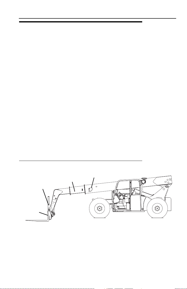
Section 5 - Attachments
OY1510
-10
1
0
20
30
40
5
0
60
70
80
DO NOT GO NEAR LEAKS
C
10814B
* High pressure oil easily punctures skin causing serious injury, gangrene or death.
* If injured, seek emergency medical help. Immediate surgery is required to remove oil.
* Do not use finger or skin to check for leaks.
* Lower load or relieve hydraulic pressure before loosening fittings.
BOOM
EXTENSION
INDICATOR
BOOM ANGLE
INDICATOR
ATTACHMENT
IDENTIFICATION
PLATE
FORK
WEIGHT
STAMP
5.5 USE OF THE CAPACITY CHART
To properly use the capacity chart (see page 5-8), the operator must first determine
and/or have the following:
1. An approved attachment. See “Approved Attachments” on page 5-1.
2. The proper Capacity Chart(s).
3. Weight of the load being lifted.
4. Load placement information:
a. HEIGHT where the load is to be placed.
b. DISTANCE from the front tires of the telehandler where the load is to be
placed.
5. On the capacity chart, find the line for the height and follow it over to the
distance.
6. The number in the load zone where the two cross is the maximum capacity for
this lift. If the two cross at a division between zones, the smaller number must
be used.
The number in the load zone must be equal to or greater than the weight of the load
to be lifted. Determine the limits of the load zone on the capacity chart and keep
within these limits.
Capacity Indicator Locations
5-73126018

Section 5 - Attachments
XXXX-XXXX
48" & 72"
CARRIAGES
MODEL
XXXXX
USE WITH:
1234-5678 48" CARRIAGE
8765-4321 72" CARRIAGE
RATED CAPACITY @ 2 FT. LOAD CENTER
48'
44'
40'
36'
32'
28'
24'
20'
16'
12'
8'
4'
0'
-4'
-8'
1
2
3
4
5
6
69°
60°
50°
40°
30°
20°
10°
0°
-6°
9000 LBS
7000 LBS
6000 LBS
5000 LBS
4000 LBS
3000 LBS
2000 LBS
1100 LBS
DEDUCT 350 LBS
FROM ALL CAPACITIES
WHEN MACHINE IS
EQUIPPED WITH WINCH
36'
0'4'8'
12'16'20'24'28'32'
OWO650
This Capacity Chart may be
used with this model ONLY.
The model of your
telehandler is indicated on
the boom or chassis.
Model XXXXX is used for
demonstration purposes only.
Boom Extension
Indicator (arc)
Load zones indicate
the maximum weight
that may be safely lifted.
These numbers must match the
model/option number stamped
on the attachment ID Plate.
Boom Angle
Sample Capacity Chart
Before S/N 0160037689
Note: This is a sample capacity chart only! DO NOT use this chart, use the one
located in your operator cab.
TIP OVER HAZARD. All loads shown on rated capacity chart are based on
machine being on firm ground with frame level (see page 4-7); the forks being
positioned evenly on carriage; the load being centered on forks; proper size tires
being properly inflated; and the telehandler being in good operating condition.
WARNING
5-8 3126018

Section 5 - Attachments
OAL1090
OAL1100
To identify the proper capacity chart on telehandlers equipped with outriggers, refer
to the following icons which may be located on the capacity chart.
• Use when lifting a load with outriggers up.
• Use when lifting a load with outriggers down.
5-93126018

Section 5 - Attachments
OY1520
XX
XX
XXXXXX
30°
50°
XXXXXXXXXX X
ANSI/ITSDF B56.6-2005
XXXX
LBS
XXXX
LBS
L
XXXX
BS
L
XXXX
BS
XXXX
BLS
XXXX
SLB
°
-4
0°
10°
20°
40°
60°
71°
1
2
3
4
5
6
7
8
9
10
+
=XXXX XX MAX
< = XX
XX
XXXX XX MAX
XXXXXXXXXXXXXXXXXXXXXXXX
XX
XX
XX
XX
XX
XX
XX
XX
XX
XX
XX
XX
XX
XX
XX
XX
This Capacity Chart may be used with this model ONLY.
The telehandler model is indicated on the boom or chassis.
Model XXXX is used for demonstration purposes only.
Boom Extension
Indicator (arc)
Boom Angle
Load zones indicate the
maximum weight that
may be safely lifted.
Load center must
be equal to or less
than value shown.
Attachment type,
weight and
dimensions must
be equal to or less
than the data
shown.
S/N 0160037689 & After
Note: This is a sample capacity chart only! DO NOT use this chart, use the one
located in your operator cab.
TIP OVER HAZARD. All loads shown on rated capacity chart are based on
machine being on firm ground with frame level (see page 4-7); the forks being
positioned evenly on carriage; the load being centered on forks; proper size tires
being properly inflated; and the telehandler being in good operating condition.
WARNING
5-10 3126018

Section 5 - Attachments
OAL1090
OAL1100
To identify the proper load chart on telehandlers equipped with outriggers, refer to
the following icons which may be located on the load chart.
• Use when lifting a load with outriggers up.
• Use when lifting a load with outriggers down.
5-113126018

Section 5 - Attachments
OY1710
0'
4'
8'
12'
16'
20'
24'
28'
32'
36'
40'
44'
-4'
0'
4'
8'
12'
16'
20'
24'
28'
32'
36'
40'
44'
48'
52'
56'
60'
48
30°
50°
4000 LBS
10000 LBS
L8000 BS
L6000 BS
5000 BLS
3000 SLB
°
-4
0°
10°
20°
40°
60°
71°
1
2
3
4
5
6
7
8
9
10
XX
Example 1
Example 2
Example 3
Example 4
Example
A contractor owns a model xxxxx telehandler with a fork carriage. He knows this
attachment may be used with his model since:
Before S/N 0160037689
• The attachment model/option number matches the attachment number on the
capacity chart.
• The capacity chart is clearly marked for model xxxxx and corresponds with
machine configuration being used.
S/N 0160037689 & After
• The attachment style, weight, dimensions and load center match the attachment
data on the capacity chart.
• The capacity chart is clearly marked for model xxxxx and corresponds with
machine configuration being used.
Below are examples with various conditions the contractor may encounter and
whether or not the load may be lifted.
Load Weight Distance Height OK to Lift
1 6000 lb (2722 kg) 18 ft (5,5 m) 12 ft (3,7 m) Yes
2 4000 lb (1814 kg) 30 ft (9,1 m) 26 ft (7,9 m) NO
3 7500 lb (3402 kg) 8 ft (2,4 m) 24 ft (7,3 m) Yes
4 5750 lb (2608 kg) 12 ft (3,7 m) 44 ft (13,4 m) NO
Note: This is a sample capacity chart only! DO NOT use this chart, use the one
located in your operator cab.
5-12 3126018

5.6 ATTACHMENT INSTALLATION
OY1830
1
2
6
4
5
3
4
5
6
1
2
3
BEFORE S/N 0160037689 S/N 0160037689 & AFTER
1. Attachment
Section 5 - Attachments
2. Attachment Pin Recess
3. Attachment Pin
4. Lock Pin
5. Retaining Pin
6. Quick Switch
(attachment tilt control in cab, see page 3-10)
WARNING
CRUSH HAZARD. Always be certain that carriage or attachment is properly
positioned on boom and is secured by lock pin and retainer pin. Failure to ensure
proper installation could permit carriage/attachment/load to disengage.
5-133126018
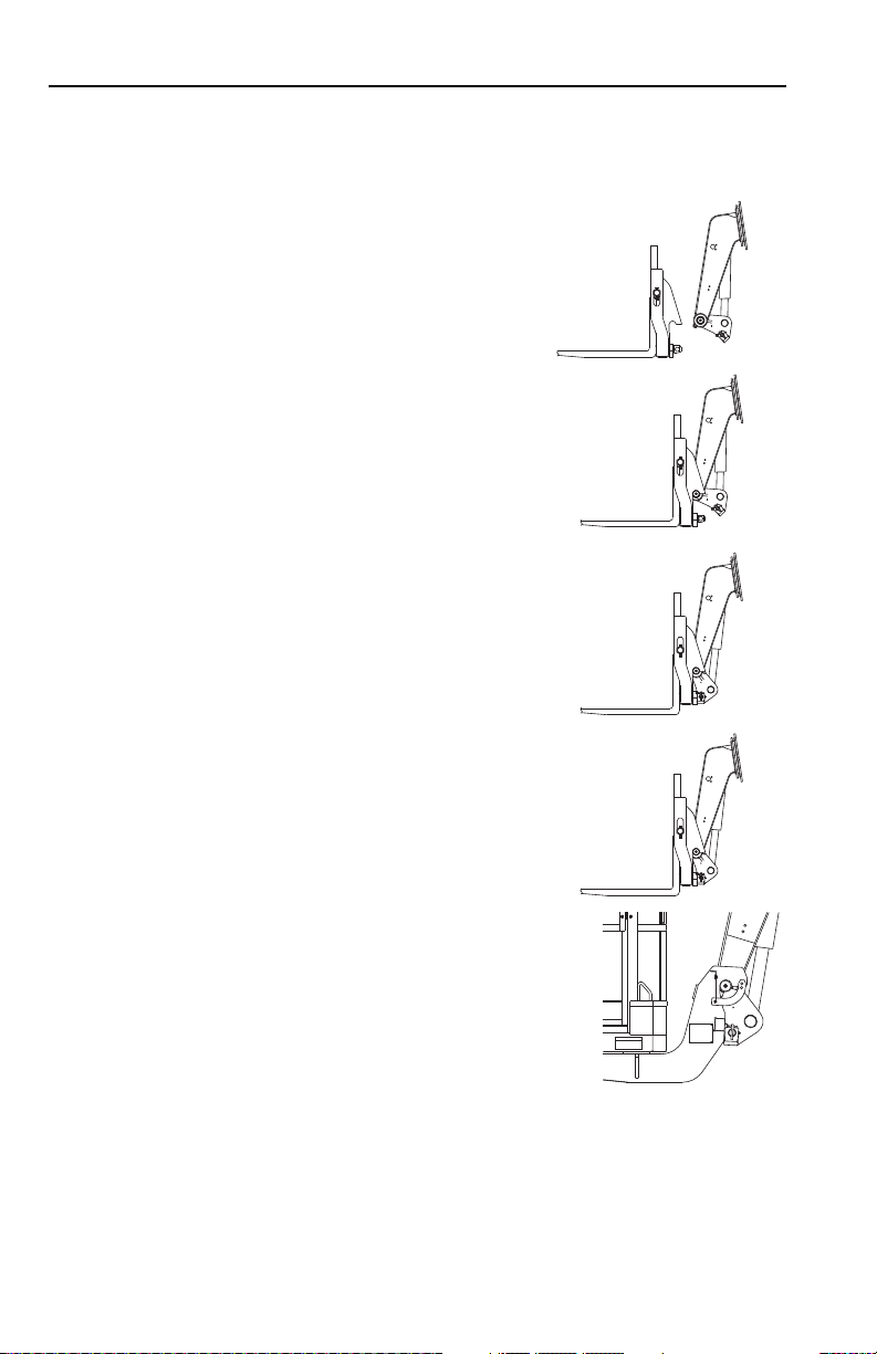
Section 5 - Attachments
OY1840
OY1850
OY1860
OY1860
OY0601
Before S/N 0160037689
This installation procedure is designed for one-person operation. Prior to exiting cab,
perform “Shut-Down Procedure” on page 4-5.
1. Tilt quick switch back to provide clearance. Check
to be sure lock pin is secured in out position with
retainer pin.
2. Align attachment pin with recess in attachment.
Raise boom slightly to engage attachment pin in
recess.
3. Tilt quick switch forward to engage attachment.
4. Remove retainer pin and slide lock pin in fully.
Secure lock pin in locked position using retainer
pin.
5. If equipped, swing attachment saddles down and
pin in place.
6. If equipped, connect auxiliary hydraulic hoses. See “Hydraulic Operated
Attachment” on page 5-16.
7. If equipped, connect auxiliary electric harness.
5-14 3126018
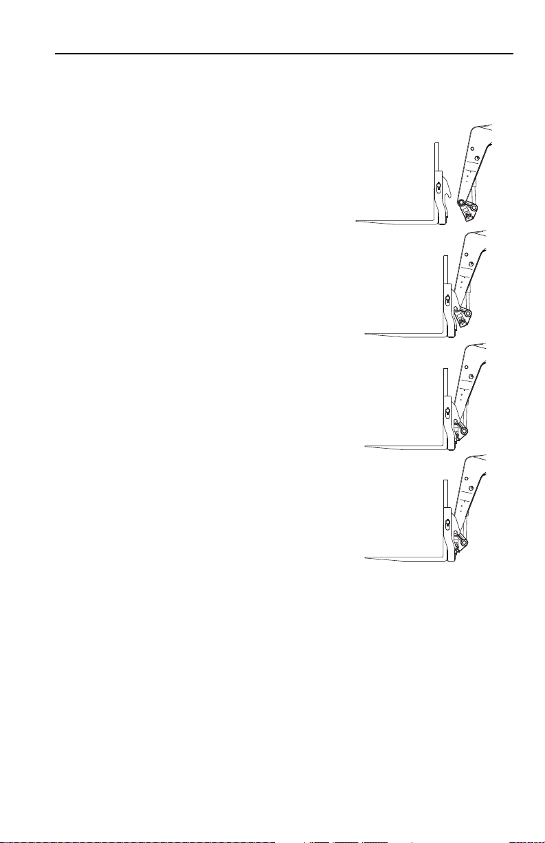
Section 5 - Attachments
OY1550
O
Y1560
OY1570
OY1580
S/N 0160037689 & After
This installation procedure is designed for one-person operation. Prior to exiting cab,
perform “Shut-Down Procedure” on page 4-5.
1. Tilt quick switch back to provide clearance.
Check to be sure lock pin is removed.
2. Align attachment pin with recess in attachment.
Raise boom slightly to engage attachment pin in
recess.
3. Tilt quick switch forward to engage attachment.
4. Lift retainer pin and insert lock pin completely
through quick switch. Release retainer pin and
ensure lock pin is secured.
5. If equipped, connect auxiliary hydraulic hoses. See “Hydraulic Operated
Attachment” on page 5-16.
6. If equipped, connect auxiliary electric harness.
5-153126018

Section 5 - Attachments
OW1240
1
OW1230
2
OY1720
2
S/N 0160037689 & AFTERBEFORE S/N 0160037689
Hydraulic Operated Attachment
1. Install attachment (see page 5-13).
2. Lower attachment to ground and perform “Shut-Down Procedure” on page 4-5.
3. Press the decompression valve button (1) to relieve auxiliary hydraulic
pressure.
4. Connect attachment hoses to both auxiliary fittings (2).
5-16 3126018

Section 5 - Attachments
5.7 ADJUSTING/MOVING FORKS
Carriages may have different locations where forks can be positioned. Two different
methods can be used for repositioning, depending upon the carriage structure.
Note: Apply a light coating of appropriate lubricant to ease sliding of forks or fork
bar.
To slide forks:
1. Ensure attachment is properly installed. See “Attachment Installation” on
page 5-13.
2. Elevate attachment to approximately 5 ft (1,5 m) and tilt carriage forward until
fork heel is free from attachment.
3. Stand at the side of the carriage. To slide fork toward the center of the carriage,
push the fork near the fork eye. To slide fork toward the edge of the carriage,
pull the fork near the fork eye. To avoid pinching, do not place fingers or thumb
between the fork and carriage structure.
If removing fork bar is necessary:
1. Rest forks on ground.
2. Remove fork bar.
3. Reposition forks.
4. Reinstall the fork bar and fork bar retaining mechanism(s).
5-173126018

Section 5 - Attachments
5.8 ATTACHMENT OPERATION
• Capacities and range limits for the telehandler change depending on the
attachment in use.
• Separate attachment instructions must be kept in manual holder in cab with this
Operation & Safety Manual. An additional copy must be kept with the attachment
if it is equipped with a manual holder.
NOTICE
EQUIPMENT DAMAGE. Some attachments may contact the front tires or
machine structure when the boom is retracted and the attachment is rotated.
Improper use of attachment may result in attachment or machine structural
damage.
NOTICE
EQUIPMENT DAMAGE. Avoid contact with any structure or object when lifting a
load. Maintain clearance around boom structure and load. Failure to maintain
clearance may result in attachment or machine structural damage.
5-18 3126018

Carriage w/Forks
OY0690
OAL0662
2
1
Use Carriage Attachment Capacity Chart
To determine maximum capacity, refer to “Telehandler/
Attachment/Fork Capacity” on page 5-6.
Section 5 - Attachments
The joystick (1) controls lift/lower and extend/retract movement of the boom.
The tilt switch (2) controls fork tilt.
• Press left side of switch to tilt up.
• Press right side of switch to tilt down.
Installation Procedure:
• Refer to “Attachment Installation” on page 5-13.
Equipment Damage Precautions:
• Do not use forks as a lever to pry material. Excessive prying forces could
damage forks or machine structure.
• Do not attempt to lift loads that are attached or connected to another object.
5-193126018

Section 5 - Attachments
OAL1550
OAL0731
2
1
3
Side Tilt Carriage
Use Side Tilt Carriage Capacity Chart
To determine maximum capacity, refer to “Telehandler/
Attachment/Fork Capacity” on page 5-6.
The joystick (1) controls lift/lower and extend/retract movement of the boom.
The tilt switch (2) controls fork tilt.
• Press left side of switch to tilt up.
• Press right side of switch to tilt down.
To Side Tilt:
The auxiliary hydraulic joystick (3) controls the carriage side tilt.
• Move joystick left to (side) tilt left.
• Move joystick right to (side) tilt right.
Installation Procedure:
• Refer to “Attachment Installation” on page 5-13.
5-20 3126018

Section 5 - Attachments
WARNING
CRUSH HAZARD. Do not use side tilt to push or pull objects or load. Failure to
comply could cause object or load to fall.
Operation:
• Approach load with forks centered on load and stop telehandler.
• Level telehandler before side tilting carriage to engage load.
• Side tilt carriage to left or right to align forks with load and engage load.
• Raise load slightly and level carriage side to side.
• Travel in accordance with the requirements set forth in Section 1 - General
Safety Practices.
Equipment Damage Precautions:
• Do not use forks as a lever to pry material. Excessive prying forces could
damage forks or machine structure.
• Do not attempt to lift loads that are attached or connected to another object.
5-213126018
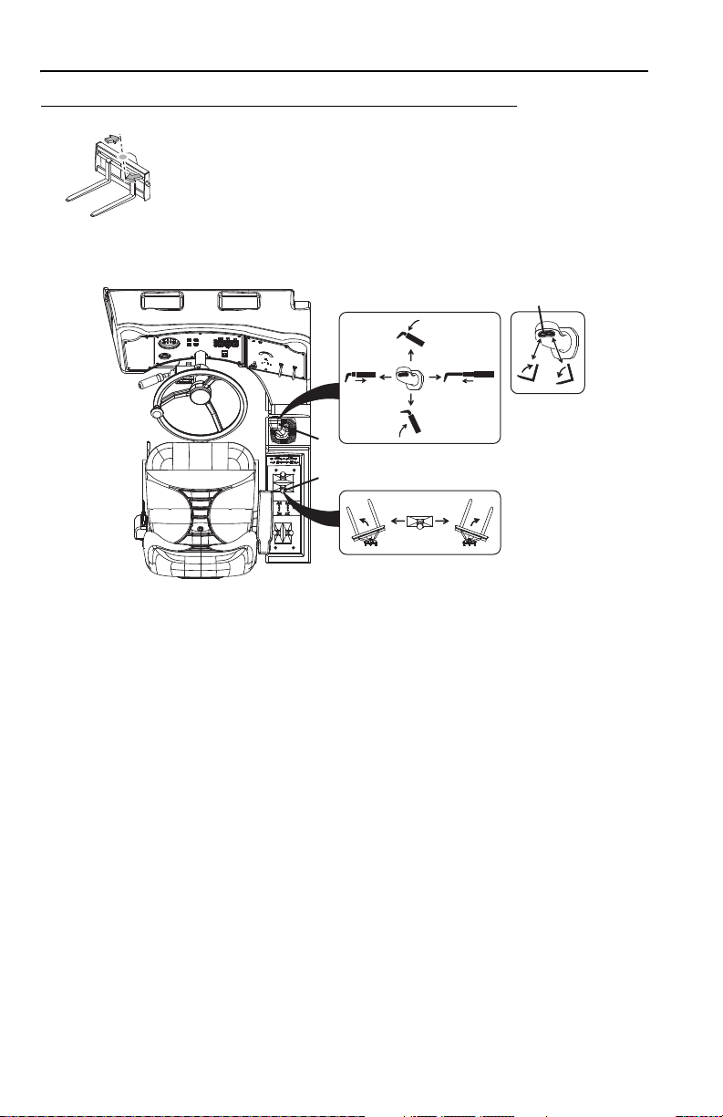
Section 5 - Attachments
OU2150
OAL1591
2
1
3
Swing Carriage
Use Swing Carriage Capacity Chart
To determine maximum capacity, refer to “Telehandler/
Attachment/Fork Capacity” on page 5-6.
The joystick (1) controls lift/lower and extend/retract movement of the boom.
The tilt switch (2) controls fork tilt.
• Press left side of switch to tilt up.
• Press right side of switch to tilt down.
To Swing:
The auxiliary hydraulic joystick (3) controls the swing function.
• Move joystick left to swing left.
• Move joystick right to swing right.
Installation Procedure:
• Refer to “Attachment Installation” on page 5-13.
5-22 3126018

Section 5 - Attachments
WARNING
CRUSH HAZARD. Always level forks (horizontally) and telehandler frame before
swinging load to side. Swinging unlevel forks could cause load to slide off forks.
WARNING
CRUSH HAZARD. Do not use swing carriage to push or pull objects or load.
Failure to comply could cause object or load to fall.
WARNING
CRUSH HAZARD. Use retaining pin (if equipped) for locking swing frame to fixed
frame when carrying loads greater than 5000 lb. Failure to comply could cause
object or load to fall.
Operation:
• To drive with a load, keep forks pointed forward and travel in accordance with the
requirements set forth in Section 1 - General Safety Practices.
Equipment Damage Precautions:
• Do not use forks as a lever to pry material. Excessive prying forces could
damage forks or machine structure.
• Do not attempt to lift loads that are attached or connected to another object.
5-233126018
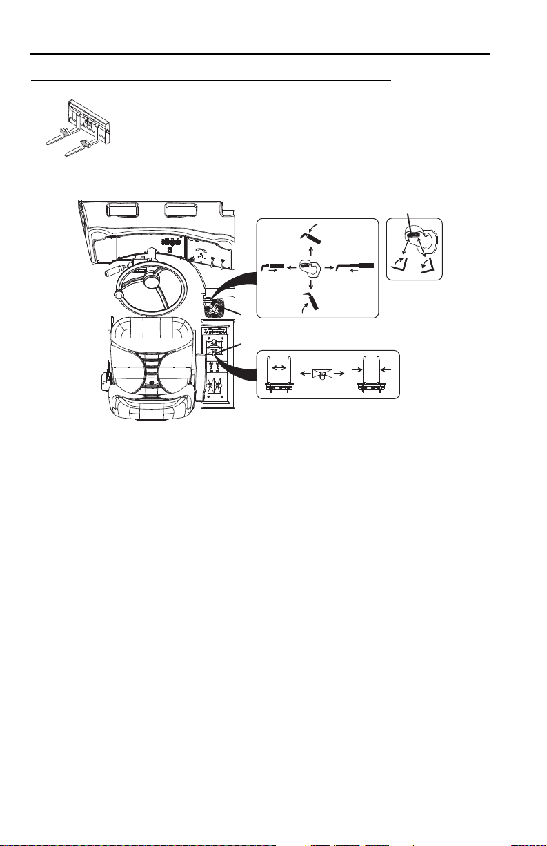
Section 5 - Attachments
OZ3670
OY3120
2
1
3
Dual Fork Positioning Carriage
Use Carriage Load Chart
To determine maximum capacity, refer to “Telehandler/
Attachment/Fork Capacity” on page 5-6.
The joystick (1) controls lift/lower and extend/retract movement of the boom.
The tilt switch (2) controls fork tilt.
• Press left side of switch to tilt up.
• Press right side of switch to tilt down.
To Fork Position:
The auxiliary hydraulic joystick (3) controls fork position.
• Move joystick left to shift forks in.
• Move joystick right to shift forks out.
Installation Procedure:
• Refer to “Attachment Installation” on page 5-13.
5-24 3126018

Section 5 - Attachments
WARNING
CRUSH HAZARD. Do not use fork positioning to push or pull objects or load.
Failure to comply could cause object or load to fall.
Operation:
• Travel in accordance with the requirements set forth in Section 1 - General
Safety Practices.
Equipment Damage Precautions:
• Do not use forks as a lever to pry material. Excessive prying forces could
damage forks or machine structure.
• Do not attempt to lift loads that are attached or connected to another object.
5-253126018
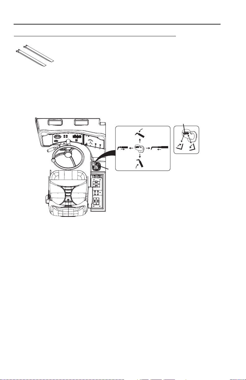
Section 5 - Attachments
OZ0750
OAL0662
2
1
Fork Extension
Use Appropriate Carriage Attachment Capacity Chart
To determine maximum capacity, refer to “Telehandler/Attachment/Fork Capacity” on
page 5-6. The maximum capacity of the carriage when equipped with fork
extensions may be reduced to the capacity indicated on the fork extensions. If the
load exceeds the capacity of the fork extension contact JLG to obtain forks and/or
fork extensions of the proper load rating and length.
The joystick (1) controls lift/lower and extend/retract movement of the boom.
The tilt switch (2) controls fork tilt.
• Press left side of switch to tilt up.
• Press right side of switch to tilt down.
Installation Procedure:
• Ensure carriage is properly installed. Refer to “Attachment Installation” on
page 5-13.
• Ensure length and cross section of the parent fork arm is equal to or exceeds the
parent fork arm blade length stamped into the fork extension.
• Secure the fork extensions to the forks by sliding the fork extensions onto the
parent forks and install the retaining pin behind the vertical shank of the fork.
5-26 3126018
 Loading...