


 Loading...
3121632 |
800S/860SJ |
3 |
4 |
800S/860SJ |
3121632 |

3121632 |
800S/860SJ |
5 |
|
|
TABLE OF CONTENTS |
SECTION 1 - FRAME........................................................................................................................................................................... |
|
9 |
FIGURE 1-1. AXLE AND STEERING INSTALLATION WITHOUT TOW PACKAGE ..................................................................... |
10 |
|
FIGURE 1-2. AXLE AND STEERING INSTALLATION WITH TOW PACKAGE ............................................................................. |
14 |
|
FIGURE 1-3. TIRE AND WHEEL DRIVE INSTALLATIONS |
........................................................................................................... |
16 |
FIGURE 1-4. DRIVE HUB/BRAKE ASSEMBLY ............................................................................................................................. |
|
20 |
FIGURE 1-5. DRIVE MOTOR ASSEMBLY .................................................................................................................................... |
|
24 |
FIGURE 1-6. FRAME VALVES AND SHIELDS INSTALLATIONS ................................................................................................. |
28 |
|
FIGURE 1-7. TOW PACKAGE INSTALLATION ............................................................................................................................. |
|
30 |
SECTION 2 - TURNTABLE................................................................................................................................................................ |
|
33 |
FIGURE 2-1. CONTROL VALVES AND AUXILIARY PUMP INSTALLATIONS ............................................................................. |
34 |
|
FIGURE 2-2. MAIN CONTROL VALVE ASSEMBLY (SN 0300182743 through 0300190436)....................................................... |
38 |
|
FIGURE 2-3. MAIN CONTROL VALVE ASSEMBLY (SN 0300190437 to Present) ....................................................................... |
40 |
|
FIGURE 2-4. TURNTABLE BEARING AND SWING DRIVE INSTALLATION................................................................................ |
42 |
|
FIGURE 2-5. SWING MOTOR/HUB ASSEMBLY........................................................................................................................... |
|
44 |
FIGURE 2-6. DEUTZ D2011 ENGINE INSTALLATION ................................................................................................................. |
|
48 |
FIGURE 2-7. DEUTZ TD2.9L4 ENGINE INSTALLATION .............................................................................................................. |
|
58 |
FIGURE 2-8. GM ENGINE INSTALLATION ................................................................................................................................... |
|
68 |
FIGURE 2-9. HYDROSTATIC PUMP ASSEMBLY......................................................................................................................... |
|
74 |
FIGURE 2-10. VARIABLE PUMP ASSEMBLY ............................................................................................................................... |
|
78 |
FIGURE 2-11. TANK INSTALLATIONS.......................................................................................................................................... |
|
82 |
FIGURE 2-12. LP TANK INSTALLATIONS (GM ENGINE MACHINES ONLY) .............................................................................. |
86 |
|
FIGURE 2-13. ROTARY COUPLING INSTALLATION ................................................................................................................... |
|
88 |
FIGURE 2-14. GROUND CONTROL BOX ASSEMBLY................................................................................................................. |
|
90 |
FIGURE 2-15. LIMIT SWITCHES, LIGHTS AND ALARM INSTALLATIONS ................................................................................. |
94 |
|
FIGURE 2-16. HOODS INSTALLATION (ABS) .............................................................................................................................. |
|
98 |
FIGURE 2-17. HOODS (STEEL) AND LIFTING PLATE INSTALLATIONS .................................................................................. |
104 |
|
FIGURE 2-18. ENGINE TRAY JACK INSTALLATION (OPTIONAL)............................................................................................ |
110 |
|
FIGURE 2-19. 7500W SKYPOWER GENERATOR INSTALLATION - DEUTZ ENGINES........................................................... |
112 |
|
FIGURE 2-20. 7500W SKYPOWER GENERATOR INSTALLATION - GM ENGINES ................................................................. |
118 |
|
SECTION 3 - BOOM ........................................................................................................................................................................ |
|
123 |
FIGURE 3-1. TOWER BOOM, UPRIGHT AND CYLINDERS INSTALLATION ............................................................................ |
124 |
|
FIGURE 3-2. MAIN BOOM INSTALLATION - 800S ..................................................................................................................... |
|
126 |
FIGURE 3-3. MAIN BOOM INSTALLATION - 860SJ ................................................................................................................... |
|
130 |
FIGURE 3-4. MAIN BOOM ASSEMBLIES ................................................................................................................................... |
|
134 |
FIGURE 3-5. ROTATOR ASSEMBLY .......................................................................................................................................... |
|
138 |
FIGURE 3-6. PLATFORM SUPPORT AND CONTROL VALVES INSTALLATIONS.................................................................... |
142 |
|
FIGURE 3-7. PLATFORM VALVE ASSEMBLIES (SN 0300182743 through 0300190436) ......................................................... |
146 |
|
FIGURE 3-8. PLATFORM VALVE ASSEMBLIES (SN 0300190437 to Present) .......................................................................... |
148 |
|
FIGURE 3-9. BOOM CABLE CLAMPS INSTALLATIONS ............................................................................................................ |
|
150 |
SECTION 4 - PLATFORM................................................................................................................................................................ |
|
153 |
FIGURE 4-1. PLATFORM ASSEMBLIES..................................................................................................................................... |
|
154 |
FIGURE 4-2. PLATFORM COMPONENTS INSTALLATION (FALL ARRREST PLATFORM) ..................................................... |
158 |
|
FIGURE 4-3. PLATFORM CONSOLE ASSEMBLY...................................................................................................................... |
|
160 |
FIGURE 4-4. CONTROLLER ASSEMBLY (LIFT AND SWING) ................................................................................................... |
164 |
|
FIGURE 4-5. CONTROLLER ASSEMBLY (DRIVE AND STEER)................................................................................................ |
166 |
|
FIGURE 4-6. SOFT TOUCH SYSTEM INSTALLATION (OPTIONAL) ......................................................................................... |
168 |
|
FIGURE 4-7. PLATFORM BUMPER PADDING INSTALLATION (OPTIONAL) ........................................................................... |
170 |
|
SECTION 5 - CYLINDER ................................................................................................................................................................. |
|
173 |
FIGURE 5-1. AXLE LOCKOUT CYLINDER ASSEMBLY ............................................................................................................. |
|
174 |
FIGURE 5-2. LIFT CYLINDER ASSEMBLY - JIB (860SJ ONLY)................................................................................................. |
176 |
|
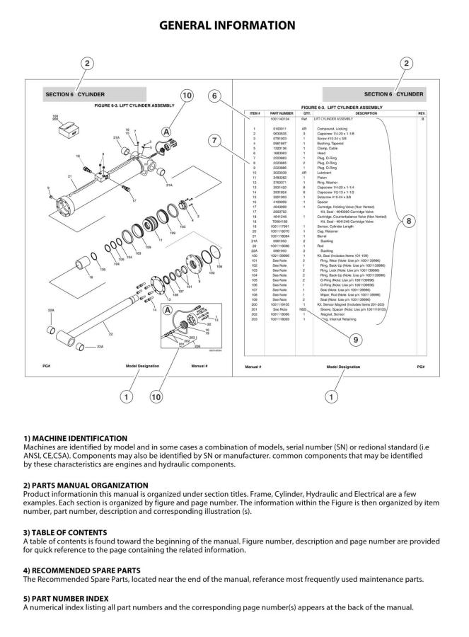
FIGURE 5-3. LIFT CYLINDER ASSEMBLY - MAIN BOOM |
......................................................................................................... |
178 |
FIGURE 5-4. PLATFORM LEVEL (SLAVE) CYLINDER ASSEMBLY .......................................................................................... |
182 |
|
FIGURE 5-5. STEER CYLINDER ASSEMBLY............................................................................................................................. |
|
184 |
FIGURE 5-6. TELESCOPE CYLINDER ASSEMBLY ................................................................................................................... |
|
186 |
SECTION 6 - HYDRAULIC .............................................................................................................................................................. |
|
189 |
3121632 |
800S/860SJ |
7 |
TABLE OF CONTENTS |
|
FIGURE 6-1. AXLE LOCKOUT HYDRAULIC DIAGRAM.............................................................................................................. |
190 |
FIGURE 6-2. DRIVE HYDRAULIC DIAGRAM - 2WD ................................................................................................................... |
192 |
FIGURE 6-3. DRIVE HYDRAULIC DIAGRAM - 4WD ................................................................................................................... |
196 |
FIGURE 6-4. MANUAL DESCENT HYDRAULIC DIAGRAM ( OPTIONAL) .................................................................................. |
200 |
FIGURE 6-5. STANDARD HYDRAULIC DIAGRAM (SN 0300182743 through 0300190436) ...................................................... |
202 |
FIGURE 6-6. STANDARD HYDRAULIC DIAGRAM (SN 0300190437 to Present) ....................................................................... |
206 |
FIGURE 6-7. HYDRAULIC DIAGRAM LIST.................................................................................................................................. |
210 |
SECTION 7 - ELECTRICAL.............................................................................................................................................................. |
211 |
FIGURE 7-1. ELECTRICAL DIAGRAM LIST ................................................................................................................................ |
212 |
FIGURE 7-2. HARNESS COMPONENTS INSTALLATION .......................................................................................................... |
214 |
SECTION 8 - DECALS ..................................................................................................................................................................... |
233 |
FIGURE 8-1. DECAL INSTALLATION (ANSI SPEC).................................................................................................................... |
234 |
FIGURE 8-2. DECAL INSTALLATION (COUNTRY SPEC) .......................................................................................................... |
238 |
FIGURE 8-3. DECAL INSTALLATION (AUSTRALIAN AND CE SPEC) ....................................................................................... |
244 |
SECTION 9 - RECOMMENDED SERVICE PARTS STOCK ............................................................................................................ |
247 |
FIGURE 9-1. MODEL 800S/860SJ STANDARD PARTS.............................................................................................................. |
248 |
FIGURE 9-2. MODEL 800S/860SJ VARIABLE PARTS ................................................................................................................ |
250 |
SECTION 10 - SPECIAL OPTIONS ................................................................................................................................................. |
251 |
FIGURE 10-1. SPECIAL OPTIONS .............................................................................................................................................. |
252 |
PART NUMBER INDEX.................................................................................................................................................................... |
257 |
8 |
800S/860SJ |
3121632 |
SECTION 1 - FRAME
SECTION 1 - FRAME
3121632 |
800S/860SJ |
9 |

SECTION 1 - FRAME
FIGURE 1-1. AXLE AND STEERING INSTALLATION WITHOUT TOW PACKAGE
10 |
800S/860SJ |
3121632 |
|
|
|
|
|
SECTION 1 - FRAME |
||
|
|
FIGURE 1-1. AXLE AND STEERING INSTALLATION WITHOUT TOW PACKAGE |
|
|
|||
|
|
|
|
|
|
|
|
|
ITEM |
|
PART NUMBER |
QTY |
DESCRIPTION |
REV |
|
|
|
|
|
|
|
|
|
|
|
|
1001151037 |
Ref |
FIXED AXLE INSTALLATION |
B |
|
|
1 |
|
0100011 |
AR |
Compound, Locking |
|
|
|
2 |
|
0641818 |
2 |
Bolt 1/2in-13NC x 2-1/4in |
|
|
|
3 |
|
0642212 |
1 |
Bolt 3/4in-10NC x 1-1/2in |
|
|
|
4 |
|
0681608 |
4 |
Bolt 3/8in-16NC x 1in Grade 8 |
|
|
|
5 |
|
0962102 |
2 |
Bushing, Garmax |
|
|
|
6 |
|
3020039 |
AR |
Lubricant |
|
|
|
7 |
|
3538047 |
AR |
Shim, Wear |
|
|
|
8 |
|
3539877 |
2 |
Plate, Stop |
|
|
|
9 |
|
3841287 |
1 |
Keeper, Pin |
|
|
|
10 |
|
4070878 |
AR |
Shim 1/16in |
|
|
|
11 |
|
4070879 |
AR |
Shim 1/8in |
|
|
|
12 |
|
4070944 |
AR |
Shim 1/16in |
|
|
|
13 |
|
4070945 |
AR |
Shim 1/4in |
|
|
|
14 |
|
4711600 |
4 |
Flatwasher 3/8in Thin |
|
|
|
15 |
|
4740472 |
1 |
Washer, Special |
|
|
|
16 |
|
1001152719 |
1 |
Axle |
|
|
|
17 |
|
1001156710 |
1 |
Pin |
|
|
|
|
|
1001154584 |
Ref |
OSCILLATING AXLE INSTALLATION |
B |
|
|
101 |
|
0100011 |
AR |
Compound, Locking |
|
|
|
102 |
|
0642212 |
1 |
Bolt 3/4in-10NC x 1-1/2in |
|
|
|
103 |
|
0681608 |
4 |
Bolt 3/8in-16NC x1in Grade 8 |
|
|
|
104 |
|
0682236 |
8 |
Bolt 3/4in-10NC x 4-1/2in Grade 8 |
|
|
|
105 |
|
0962102 |
2 |
Bushing, Garmax |
|
|
|
106 |
|
3020039 |
AR |
Lubricant |
|
|
|
107 |
|
3538047 |
AR |
Shim, Axle Wear |
|
|
|
108 |
|
3841287 |
1 |
Shaft, Keeper 3/8in Dia x 6in |
|
|
|
109 |
|
4070878 |
AR |
Shim, Axle Wear |
|
|
|
110 |
|
4070879 |
AR |
Shim, Axle Wear |
|
|
|
111 |
|
4711600 |
4 |
Flatwasher 3/8in Thin |
|
|
|
112 |
|
4740472 |
1 |
Washer, Special |
|
|
|
113 |
|
4892200 |
8 |
Flatwasher 3/4in Hardened |
|
|
|
114 |
|
1001152719 |
1 |
Axle |
|
|
|
115 |
|
1001154258 |
2 |
Axle Lockout Cylinder Assembly (See CYLINDER SECTION for |
|
|
|
|
|
|
|
Breakdown) |
|
|
|
116 |
|
1001156710 |
1 |
Pin |
|
|
|
|
|
1001151034 |
Ref |
STEERING INSTALLATIONS (2WS) |
E |
|
|
201 |
|
0100011 |
AR |
Compound, Locking |
|
|
|
202 |
|
0641607 |
4 |
Bolt 3/8in-16NC x 7/8in |
|
|
|
203 |
|
0641810 |
16 |
Bolt 1/2in-13NC x 1-1/4in |
|
|
|
204 |
|
3020029 |
AR |
Lubricant |
|
|
|
205 |
|
3422417 |
2 |
Pin |
|
|
|
206 |
|
3422790 |
2 |
Pin |
|
|
|
207 |
|
3841520 |
4 |
Keeper, Pin |
|
|
|
208 |
|
4740256 |
AR |
Thrustwasher |
|
|
|
209 |
|
4740473 |
2 |
Washer, Special |
|
|
|
210 |
|
1001103810 |
AR |
Thrustwasher |
|
|
|
211 |
|
1001165657 |
4 |
Bearing |
|
|
|
212 |
|
1001150372 |
2 |
Spindle |
|
|
|
213 |
|
1001150539 |
2 |
Steer Cylinder Assembly (See CYLINDER SECTION for |
|
|
3121632 |
|
|
|
800S/860SJ |
11 |
||
SECTION 1 - FRAME
ITEM |
PART NUMBER |
QTY |
DESCRIPTION |
REV |
|
|
|
|
|
|
|
|
Breakdown) |
|
214 |
1001161355 |
4 |
Kingpin |
|
215 |
1001150937 |
4 |
Plate |
|
216 |
1001151980 |
1 |
Tie-Rod |
|
217 |
1001161399 |
2 |
Thrustwasher |
|
218 |
4740463 |
AR |
Thrustwasher |
|
12 |
800S/860SJ |
3121632 |
SECTION 1 - FRAME
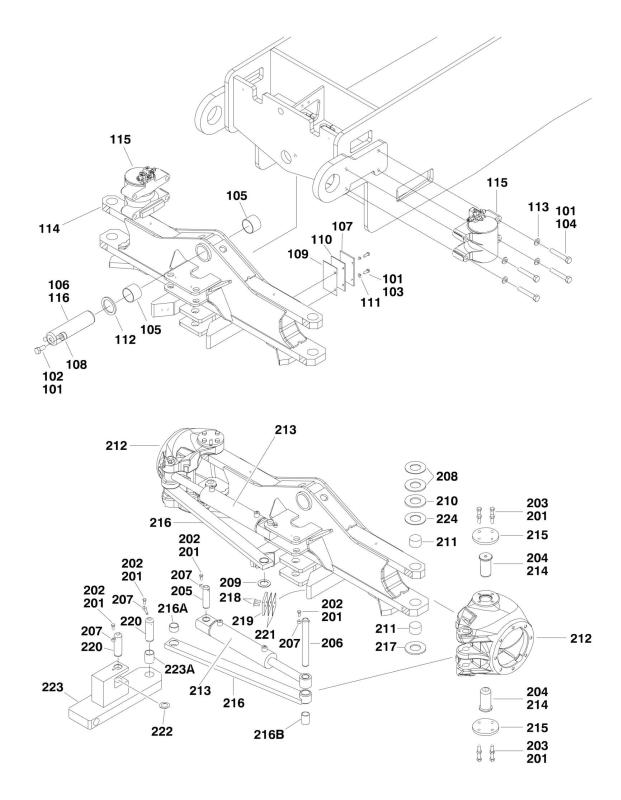
FIGURE 1-2. AXLE AND STEERING INSTALLATION WITH TOW PACKAGE
14 |
800S/860SJ |
3121632 |
|
|
|
SECTION 1 - FRAME |
||
|
FIGURE 1-2. AXLE AND STEERING INSTALLATION WITH TOW PACKAGE |
|
|
||
|
|
|
|
|
|
ITEM |
PART NUMBER |
QTY |
DESCRIPTION |
REV |
|
|
|
|
|
|
|
|
1001155194 |
Ref |
OSCILLATING AXLE INSTALLATION |
B |
|
101 |
0100011 |
AR |
Compound, Locking |
|
|
102 |
0642212 |
1 |
Bolt 3/4in-10NC x 1-1/2in |
|
|
103 |
0681608 |
4 |
Bolt 3/8in-16NC x1in Grade 8 |
|
|
104 |
0682236 |
8 |
Bolt 3/4in-10NC x 4-1/2in Grade 8 |
|
|
105 |
0962102 |
2 |
Bushing, Garmax |
|
|
106 |
3020039 |
AR |
Lubricant |
|
|
107 |
3538047 |
AR |
Shim, Axle Wear |
|
|
108 |
3841287 |
1 |
Shaft, Keeper 3/8in Dia x 6in |
|
|
109 |
4070878 |
AR |
Shim, Axle Wear |
|
|
110 |
4070879 |
AR |
Shim, Axle Wear |
|
|
111 |
4711600 |
4 |
Flatwasher 3/8in Thin |
|
|
112 |
4740472 |
1 |
Washer, Special |
|
|
113 |
4892200 |
8 |
Flatwasher 3/4in Hardened |
|
|
114 |
1001154875 |
1 |
Axle |
|
|
115 |
1001154258 |
2 |
Axle Lockout Cylinder Assembly (See CYLINDER SECTION for |
|
|
|
|
|
Breakdown) |
|
|
116 |
1001156710 |
1 |
Pin |
|
|
|
1001155192 |
Ref |
STEERING INSTALLATION |
D |
|
201 |
0100011 |
AR |
Compound, Locking |
|
|
202 |
0641607 |
6 |
Bolt 3/8in-16NC x 7/8in |
|
|
203 |
0641810 |
16 |
Bolt 1/2in-13NC x 1-1/4in |
|
|
204 |
3020029 |
AR |
Lubricant |
|
|
205 |
3422417 |
2 |
Pin |
|
|
206 |
3422790 |
2 |
Pin |
|
|
207 |
3841520 |
6 |
Keeper, Pin |
|
|
208 |
4740256 |
AR |
Thrustwasher |
|
|
209 |
4740473 |
2 |
Washer, Special |
|
|
210 |
1001103810 |
AR |
Thrustwasher |
|
|
211 |
1001165657 |
4 |
Bearing |
|
|
212 |
1001150372 |
2 |
Spindle |
|
|
213 |
1001150539 |
2 |
Steer Cylinder Assembly (See CYLINDER SECTION for |
|
|
|
|
|
Breakdown) |
|
|
214 |
1001161355 |
4 |
Kingpin |
|
|
215 |
1001150937 |
4 |
Plate |
|
|
216 |
1001154931 |
2 |
Tie-Rod |
|
|
216A |
0962181 |
1 |
Bushing |
|
|
216B |
0962152 |
1 |
Bushing |
|
|
217 |
1001161399 |
2 |
Thrustwasher |
|
|
218 |
0741609 |
4 |
Screw 3/8in-16NC x 1-1/8in |
|
|
219 |
3340966 |
2 |
Pad, Stop |
|
|
220 |
3422848 |
2 |
Pin, Hitch |
|
|
221 |
4071059 |
AR |
Shim |
|
|
222 |
4740155 |
3 |
Thrustwasher |
|
|
223 |
1001155035 |
1 |
Link |
|
|
223A |
0962348 |
1 |
Bushing |
|
|
224 |
4740463 |
AR |
Thrustwasher |
|
|
3121632 |
800S/860SJ |
15 |

SECTION 1 - FRAME
FIGURE 1-3. TIRE AND WHEEL DRIVE INSTALLATIONS
16 |
800S/860SJ |
3121632 |
|
|
|
|
SECTION 1 - FRAME |
||
|
|
FIGURE 1-3. TIRE AND WHEEL DRIVE INSTALLATIONS |
|
|
||
|
|
|
|
|
|
|
|
ITEM |
PART NUMBER |
QTY |
DESCRIPTION |
REV |
|
|
|
|
|
|
|
|
|
|
|
Ref |
WHEEL DRIVE INSTALLATION |
|
|
|
|
1001157015 |
Ref |
2WD |
A |
|
|
|
1001157016 |
Ref |
4WD |
A |
|
|
|
|
Ref |
Note: 2WD Qty Shown. For 4WD, Double Qty Shown. |
|
|
|
1 |
0100011 |
AR |
Compound, Locking |
|
|
|
3 |
3311801 |
4 |
Nut 1/2in-13 NC |
|
|
|
4 |
0682016 |
16 |
Bolt 5/8in-11NC x 2in Grade 8 |
|
|
|
5 |
2300016 |
AR |
Fluid, Hydraulic (Not Shown) |
|
|
|
6 |
2780272 |
2 |
Drive Hub Assembly (See DRIVE HUB ASSEMBLY for |
|
|
|
|
|
|
Breakdown) |
|
|
|
7 |
3020008 |
AR |
Lubricant (Not Shown) |
|
|
|
8 |
|
Ref |
Drive Motor Assembly Options (See DRIVE MOTOR |
|
|
|
|
|
|
ASSEMBLY for Breakdown): |
|
|
|
8 |
3160347 |
2 |
2WD Rear |
|
|
|
8 |
3160348 |
4 |
4WD Front and Rear |
|
|
|
9 |
3300007 |
20 |
Nut, Wheel |
|
|
|
13 |
4891800 |
4 |
Flatwasher, 1/2in Hardened |
|
|
|
14 |
4892000 |
16 |
Flatwasher 5/8in Hardened |
|
|
|
|
1001157015 |
Ref |
HUB INSTALLATION (2WD ONLY) |
A |
|
|
101 |
0100011 |
AR |
Compound, Locking |
|
|
|
104 |
0682016 |
16 |
Bolt 5/8in-16NC x 2in Grade 8 |
|
|
|
106 |
2780229 |
2 |
Hub Assembly (See Items 201-212 for Breakdown) |
|
|
|
110 |
3300007 |
20 |
Lugnut |
|
|
|
115 |
4892000 |
16 |
Flatwasher 5/8in Hardened |
|
|
|
|
2780229 |
Ref |
HUB ASSEMBLY (2WD ONLY) |
A |
|
|
201 |
7017052 |
2 |
Spindle (1 per Assembly) |
|
|
|
202 |
7017053 |
2 |
Housing (1 per Assembly) |
|
|
|
203 |
7010404 |
2 |
Cup, Bearing - Inner (1 per Assembly) |
|
|
|
204 |
7010405 |
2 |
Cone, Bearing - Inner (1 per Assembly) |
|
|
|
205 |
7017056 |
2 |
Cup, Bearing - Outer (1 per Assembly) |
|
|
|
206 |
7017055 |
2 |
Cone, Bearing - Outer (1 per Assembly) |
|
|
|
207 |
7010406 |
2 |
Seal, Lip (1 per Assembly) |
|
|
|
208 |
7000265 |
20 |
Stud (10 per Assembly) |
|
|
|
209 |
7017054 |
2 |
Dust Cap (1 per Assembly) |
|
|
|
210 |
7017051 |
2 |
Washer, Special (1 per Assembly) |
|
|
|
211 |
7017057 |
2 |
Washer, Tanged (1 per Assembly) |
|
|
|
212 |
7017058 |
2 |
Nut, Bearing (1 per Assembly) |
|
|
|
|
|
Ref |
TIRE AND WHEEL INSTALLATIONS |
|
|
|
|
0270885 |
Ref |
15-625 NHS Pneumatic (Available on All Specs Except |
C |
|
|
|
|
|
Australian and CE Specs) |
|
|
|
|
0272322 |
Ref |
15-625 NHS Pneumatic W/Sealant (Available on ANSI Specs |
C |
|
|
|
|
|
Only) |
|
|
|
|
0270886 |
Ref |
15-625 NHS Foam-Filled (Available on All Specs) |
C |
|
|
|
0270888 |
Ref |
18-625 NHS Foam-Filled (Available on All Specs) |
C |
|
|
|
0271083 |
2 |
15-625 NHS Pneumatic Left Side |
|
|
|
|
0271084 |
2 |
15-625 NHS Pneumatic Right Side |
|
|
|
|
0272334 |
2 |
15-625 NHS Pneumatic W/Sealant Left Side |
|
|
|
|
0272333 |
2 |
15-625 NHS Pneumatic W/Sealant Right Side |
|
|
|
|
0271085 |
2 |
15-625 NHS Foam-Filled Left Side |
|
|
|
|
0271086 |
2 |
15-625 NHS Foam-Filled Right Side |
|
|
3121632 |
|
|
800S/860SJ |
17 |
||
SECTION 1 - FRAME
ITEM |
PART NUMBER |
QTY |
DESCRIPTION |
REV |
|
|
|
|
|
|
0271090 |
2 |
18-625 NHS Foam-Filled Left Side |
|
|
0271091 |
2 |
18-625 NHS Foam-Filled Right Side |
|
|
|
Ref |
Note: Assemblies may require ballast/foam filling to |
|
|
|
|
manufacturer's specifications prior to installing on a |
|
|
|
|
machine. Refer to Operation and Safety or Service and |
|
|
|
|
Maintenance Manuals. Purchase individual tire and/or rim |
|
|
|
|
only if able to foam fill tire and wheel assembly, otherwise, |
|
|
|
|
purchase complete assembly. |
|
301 |
1702701 |
1 |
Decal - 95psi/6.5 Bar (15-625 Tires) (Pneumatic Only) |
|
302 |
|
Ref |
Tire Options: |
|
302 |
4520252 |
1 |
15-625 Tire |
|
302 |
4520253 |
1 |
18-625 Tire |
|
303 |
4640113 |
1 |
Valve, Air |
|
304 |
|
Ref |
Rim, Wheel Options: |
|
304 |
4860224 |
1 |
13 x 24.5 Rim (Use with 15-625 Tires) |
|
304 |
4860225 |
1 |
15 x 24.5 Rim (Use with 18-625 Tires) |
|
305 |
1705364 |
AR |
Decal - Tire Sealant (W/Sealant Only) |
|
306 |
1300019 |
AR |
Chemical, Tire Sealant (Green) (W/Sealant Only) |
|
307 |
1120552 |
AR |
Cap, Valve Stem (Green) (W/Sealant Only) |
|
18 |
800S/860SJ |
3121632 |

SECTION 1 - FRAME
FIGURE 1-4. DRIVE HUB/BRAKE ASSEMBLY
20 |
800S/860SJ |
3121632 |
|
|
|
|
|
SECTION 1 - FRAME |
||
|
|
|
FIGURE 1-4. DRIVE HUB/BRAKE ASSEMBLY |
|
|
||
|
|
|
|
|
|
|
|
|
ITEM |
PART NUMBER |
|
QTY |
DESCRIPTION |
REV |
|
|
|
|
|
|
|
|
|
|
|
2780272 |
|
Ref |
DRIVE HUB/BRAKE ASSEMBLY |
B |
|
|
|
2780227 |
|
Ref |
Hub Assembly |
B |
|
|
1 |
See Note |
|
1 |
Spindle/Housing Assembly (Note: Not Available - Purchase |
|
|
|
|
|
|
|
Individual Components.) |
|
|
|
1A |
7010464 |
|
1 |
Spindle |
|
|
|
1B |
7000236 |
|
1 |
Seal |
|
|
|
1C |
7000273 |
|
1 |
Cone, Bearing |
|
|
|
1D |
7000272 |
|
1 |
Cup, Bearing |
|
|
|
1E |
7000275 |
|
1 |
Cone, Bearing |
|
|
|
1F |
7000274 |
|
1 |
Cup, Bearing |
|
|
|
1G |
7017033 |
|
1 |
Housing |
|
|
|
1H |
7000239 |
|
1 |
Thrustwasher |
|
|
|
1I |
7000240 |
|
1 |
Ring, Retaining |
|
|
|
1J |
7001928 |
|
1 |
Plug, Pipe |
|
|
|
1N |
7000265 |
|
10 |
Stud, Wheel |
|
|
|
2 |
7024782 |
|
1 |
Gear, Ring |
|
|
|
3 |
See Note |
|
1 |
Carrier Assembly (Note: Not Available - Purchase Individual |
|
|
|
|
|
|
|
Components.) |
|
|
|
3A |
7024147 |
|
1 |
Carrier |
|
|
|
3B |
7001901 |
|
6 |
Thrustwasher, Tanged |
|
|
|
3C |
7001902 |
|
96 |
Bearing, Needle |
|
|
|
3D |
7001903 |
|
3 |
Spacer, Thrust |
|
|
|
3E |
7024146 |
|
3 |
Shaft, Planet |
|
|
|
3F |
7024148 |
|
3 |
Gear, Cluster |
|
|
|
3G |
7001906 |
|
3 |
Rollpin |
|
|
|
4 |
7024151 |
|
1 |
Gear, Internal |
|
|
|
5 |
7000224 |
|
1 |
O-Ring |
|
|
|
6 |
See Note |
|
1 |
Cover Assembly (Note: Not Available - Purchase Individual |
|
|
|
|
|
|
|
Components.) |
|
|
|
6A |
7024155 |
|
1 |
Cover |
|
|
|
6B |
7024783 |
|
1 |
Cap |
|
|
|
6C |
7000220 |
|
4 |
Bolt 1/4in-20NC x 3/4in |
|
|
|
6D |
7000231 |
|
1 |
Cap, Disengage |
|
|
|
6E |
7000235 |
|
1 |
Rod, Disengage |
|
|
|
6F |
7000213 |
|
1 |
O-Ring |
|
|
|
6G |
7000238 |
|
1 |
O-Ring |
|
|
|
6H |
7017048 |
|
1 |
Plug, Pipe |
|
|
|
7 |
7000282 |
|
2 |
Thrustwasher |
|
|
|
8 |
7000283 |
|
1 |
O-Ring |
|
|
|
9 |
7000284 |
|
1 |
Ring, Retaining |
|
|
|
10 |
7000285 |
|
1 |
Ring, Retaining |
|
|
|
11 |
7024781 |
|
1 |
Shaft, Input |
|
|
|
12 |
7024154 |
|
1 |
Spacer, Input |
|
|
|
13 |
7024149 |
|
1 |
Gear, Sun |
|
|
|
15 |
7000287 |
|
4 |
Thrustwasher |
|
|
|
16 |
7000288 |
|
2 |
Thrustwasher |
|
|
|
17 |
7000289 |
|
12 |
Bolt 3/8in-16NC x 2-1/2in (Grade 8) |
|
|
|
19 |
7000290 |
|
1 |
Coupling |
|
|
|
20 |
7017047 |
|
2 |
Pin, Dowel |
|
|
|
21 |
7017050 |
|
1 |
Thrustwasher |
|
|
3121632 |
|
|
|
800S/860SJ |
21 |
||
SECTION 1 - FRAME
ITEM |
PART NUMBER |
QTY |
DESCRIPTION |
REV |
|
|
|
|
|
26 |
7024182 |
1 |
Brake Assembly (Includes Items 101-123) |
|
27 |
7024763 |
2 |
O-Ring |
|
28 |
7024717 |
2 |
Stud 1/2in-13NC x 4-5/8in |
|
29 |
7024718 |
2 |
Nut 1/2in-13NC |
|
31 |
7000731 |
1 |
Gasket |
|
|
7024182 |
Ref |
BRAKE ASSEMBLY |
|
101 |
7024189 |
1 |
Shaft |
|
102 |
See Note |
1 |
Housing (Note: Not Available - Purchase Complete Assy.) |
|
103 |
7024193 |
2 |
Plate, Friction |
|
104 |
7024193 |
1 |
Plate, Pressure |
|
105 |
7000731 |
1 |
Gasket |
|
106 |
7024193 |
2 |
Plate, Outer |
|
107 |
See Note |
1 |
Gasket (Note: Use Items 200B, 201C or 201D) |
|
108 |
7024191 |
1 |
Cylinder |
|
109 |
7024192 |
1 |
Piston |
|
110 |
7024197 |
1 |
Bearing, Ball |
|
111 |
7024197 |
1 |
Ring, Retaining |
|
112 |
7024197 |
1 |
Seal, Shaft |
|
113 |
See Note |
6 |
Capscrew (Note: Not Available for Purchase.) |
|
114 |
See Note |
6 |
Lockwasher (Note: Not Available for Purchase.) |
|
115 |
7024194 |
1 |
O-Ring |
|
116 |
7024194 |
1 |
Ring, Back-up |
|
117 |
7024194 |
1 |
O-Ring |
|
118 |
7024194 |
1 |
Ring, Back-up |
|
119 |
7024190 |
2 |
Pin, Dowel |
|
120 |
See Note |
1 |
Plug (Note: Not Available for Purchase.) |
|
121 |
See Note |
2 |
Plug (Note: Not Available for Purchase.) |
|
122 |
7024196 |
10 |
Spring Kit (Natural) |
|
123 |
7024196 |
2 |
Spring Kit (Blue) |
|
|
|
Ref |
KIT OPTIONS: |
|
200 |
|
Ref |
Seal Kit Options: |
|
200A |
7017068 |
1 |
Seal Kit - Hub (Includes Items 1B,1I, 5, 6F, 6G, 15 & 16) |
|
200B |
7024194 |
1 |
Seal Kit - 7024182 Brake (Includes Items 105, 107 & 215-218) |
|
201 |
|
Ref |
Repair Kit Options: |
|
201A |
7024196 |
1 |
Spring Kit - 7024182 Brake (Includes 12 Natural Colored |
|
|
|
|
Springs) (was p/n 7024195) (Note: Spring Kit no Longer |
|
|
|
|
Available, Purchase Kit p/n 7024196.) |
|
201B |
7024196 |
1 |
Spring Kit - 7024182 Brake (Includes 12 Natural and 2 Blue |
|
|
|
|
Colored Springs) |
|
201C |
7024193 |
1 |
Friction Disc Kit - 7024182 Brake (Includes Items 103, 104, 106 |
|
|
|
|
& 107) |
|
201D |
7024197 |
1 |
Bearing Kit - 7024182 Brake (Includes Items 107 & 110-112) |
|
22 |
800S/860SJ |
3121632 |

SECTION 1 - FRAME
FIGURE 1-5. DRIVE MOTOR ASSEMBLY
24 |
800S/860SJ |
3121632 |
|
|
|
|
SECTION 1 - FRAME |
||
|
|
|
FIGURE 1-5. DRIVE MOTOR ASSEMBLY |
|
|
|
|
|
|
|
|
|
|
|
ITEM |
PART NUMBER |
QTY |
DESCRIPTION |
REV |
|
|
|
|
|
|
|
|
|
|
|
Ref |
DRIVE MOTOR ASSEMBLIES: |
|
|
|
|
3160347 |
Ref |
2WD |
B |
|
|
|
3160348 |
Ref |
4WD |
B |
|
|
1 |
7022302 |
2 |
Bearing, Journal |
|
|
|
2 |
7007446 |
1 |
Pin |
|
|
|
3 |
7007438 |
2 |
Ring, Retaining |
|
|
|
4 |
|
Ref |
Swashplate Options: |
|
|
|
4 |
70000794 |
1 |
2WD |
|
|
|
4 |
7022305 |
1 |
4WD |
|
|
|
5 |
See Note |
2 |
Pin (Note: Not Available for Purchase.) |
|
|
|
6 |
7022328 |
1 |
Gasket |
|
|
|
7 |
|
Ref |
Cylinder Block Kit (Includes Items 7A & 9-17) |
|
|
|
7 |
7027740 |
1 |
2WD |
|
|
|
7 |
7023907 |
1 |
4WD |
|
|
|
7A |
See Note |
1 |
Block, Cylinder (Note: Not Available - Purchase Complete |
|
|
|
|
|
|
Cylinder Block Kit.) |
|
|
|
8 |
|
Ref |
Plate, Valve Options: |
|
|
|
8 |
7024862 |
1 |
2WD |
|
|
|
8 |
7023908 |
1 |
4WD |
|
|
|
9 |
|
Ref |
Guide, Slipper Retainer Options: |
|
|
|
9 |
See Note |
1 |
2WD (Note: Not Available for Purchase.) |
|
|
|
9 |
7021277 |
1 |
4WD |
|
|
|
10 |
7021275 |
3 |
Pin, Slipper Hold Down |
|
|
|
11 |
See Note |
9 |
Piston Assembly (Note: Not Available - Purchase Complete |
|
|
|
|
|
|
Assy.) |
|
|
|
12 |
|
Ref |
Retainer, Slipper Options: |
|
|
|
12 |
See Note |
1 |
2WD (Note: Not Available for Purchase.) |
|
|
|
12 |
7022310 |
1 |
4WD |
|
|
|
13 |
|
Ref |
Retainer, Hold Down Pin Options: |
|
|
|
13 |
Not Required |
0 |
2WD |
|
|
|
13 |
7021276 |
1 |
4WD |
|
|
|
14 |
7022311 |
1 |
Ring, Retaining |
|
|
|
15 |
|
Ref |
Spring Options: |
|
|
|
15 |
7024867 |
1 |
2WD |
|
|
|
15 |
7022312 |
1 |
4WD |
|
|
|
16 |
|
Ref |
Washer Options: |
|
|
|
16 |
7022313 |
1 |
2WD |
|
|
|
16 |
7024868 |
1 |
4WD |
|
|
|
17 |
7022314 |
1 |
Retainer, Spring |
|
|
|
18 |
7023910 |
1 |
Shaft |
|
|
|
19 |
7007439 |
1 |
Ring, Retaining |
|
|
|
20 |
|
Ref |
Cap, End - Axial Options: |
|
|
|
20 |
70000795 |
1 |
2WD |
|
|
|
20 |
70000797 |
1 |
4WD |
|
|
|
21 |
7022368 |
5 |
Screw |
|
|
|
22 |
7021249 |
1 |
Bearing, Needle |
|
|
|
23 |
2220886 |
1 |
Plug (Includes Item 24) |
|
|
|
24 |
7022328 |
1 |
O-Ring |
|
|
|
25 |
2220883 |
1 |
Plug (Includes Item 26) |
|
|
|
26 |
7022328 |
1 |
O-Ring |
|
|
3121632 |
|
|
800S/860SJ |
25 |
||
SECTION 1 - FRAME
ITEM |
PART NUMBER |
QTY |
DESCRIPTION |
REV |
|
|
|
|
|
27 |
2220888 |
2 |
Plug (Includes Item 28) |
|
28 |
7022328 |
2 |
O-Ring |
|
29 |
|
Ref |
Seat, Spring Options: |
|
29 |
7027741 |
1 |
2WD |
|
29 |
7022372 |
1 |
4WD |
|
30 |
See Note |
1 |
Housing (Note: Not Available - Purchase Complete Assy.) |
|
31 |
2220883 |
2 |
Plug (Items Item 32) |
|
32 |
7022328 |
2 |
O-Ring |
|
33 |
2220886 |
1 |
Plug (Items Item 34) |
|
34 |
7022328 |
1 |
O-Ring |
|
35 |
7022328 |
1 |
O-Ring |
|
36 |
7022328 |
1 |
Ring, Seal |
|
37 |
|
Ref |
Piston, Servo Options (Includes Items 35 & 36): |
|
37 |
7024871 |
1 |
2WD |
|
37 |
7024854 |
1 |
4WD |
|
38 |
7007437 |
1 |
Bearing |
|
39 |
7022326 |
1 |
Spring |
|
40 |
7022328 |
1 |
Seal, Lip |
|
41 |
7022371 |
1 |
Washer, Support |
|
|
|
Ref |
KIT OPTIONS: |
|
100 |
7022328 |
1 |
Seal Kit (Includes Items 6, 24, 26, 28, 32, 34, 35, 36 & 40) |
|
26 |
800S/860SJ |
3121632 |

SECTION 1 - FRAME
FIGURE 1-6. FRAME VALVES AND SHIELDS INSTALLATIONS
28 |
800S/860SJ |
3121632 |
|
|
|
|
SECTION 1 - FRAME |
||
|
FIGURE 1-6. FRAME VALVES AND SHIELDS INSTALLATIONS |
|||||
|
|
|
|
|
|
|
ITEM |
PART NUMBER |
QTY |
DESCRIPTION |
|
REV |
|
|
|
|
|
|
|
|
|
1001157015 |
Ref |
DRIVE VALVES INSTALLATION - 2WD |
|
A |
|
2 |
0641542 |
2 |
Bolt 5/16in-18NC x 5-1/4in |
|
|
|
11 |
3311505 |
2 |
Locknut 5/16in-18NC |
|
|
|
12 |
1001099870 |
1 |
Flow Divider Valve Assembly |
|
A |
|
12A |
7023933 |
1 |
Cartridge, Flow Divider |
|
|
|
12A |
7021625 |
1 |
Seal Kit - 7023933 Cartridge |
|
|
|
12A |
70000781 |
1 |
Lockdown Kit |
|
|
|
12B |
7022397 |
2 |
Cartridge, Check |
|
|
|
12B |
7022399 |
2 |
Seal Kit - 7022397 Cartridge |
|
|
|
12C |
70002390 |
2 |
Cartridge, Check |
|
|
|
12C |
7022399 |
2 |
Seal Kit - 70002390 Cartridge |
|
|
|
12D |
7024881 |
1 |
Piston, Pilot |
|
|
|
12E |
7017406 |
1 |
Plug |
|
|
|
12F |
7024844 |
1 |
Plug |
|
|
|
12F |
7017492 |
1 |
Orifice |
|
|
|
13 |
4711500 |
4 |
Flatwasher 5/16in Thin |
|
|
|
|
1001157016 |
Ref |
DRIVE VALVES INSTALLATION - 4WD |
|
A |
|
102 |
0641560 |
3 |
Bolt 5/16in-18NC x 7-1/2in |
|
|
|
110 |
3311505 |
3 |
Locknut 5/16in-18NC |
|
|
|
111 |
4641303 |
1 |
Flow Divider Valve Assembly |
|
|
|
111A |
7023933 |
1 |
Cartridge, Flow Divider |
|
|
|
111A |
7021625 |
1 |
Seal Kit - 7023933 Cartridge |
|
|
|
111B |
7022397 |
6 |
Cartridge, Check |
|
|
|
111B |
7022399 |
6 |
Seal Kit - 7022397 Cartridge |
|
|
|
111C |
7021639 |
2 |
Cartridge, Check Valves |
|
|
|
111C |
2900756 |
2 |
Seal Kit - 7022398 Cartridge |
|
|
|
111D |
7024881 |
1 |
Piston, Pilot |
|
|
|
111E |
7023917 |
2 |
Cartridge, Flow Divider |
|
|
|
111E |
7021625 |
2 |
Seal Kit - 7023917 Cartridge |
|
|
|
111F |
70003935 |
2 |
Orifice |
|
|
|
111G |
70003936 |
1 |
Orifice |
|
|
|
112 |
4711500 |
6 |
Flatwasher 5/16in Thin |
|
|
|
|
1001158203 |
Ref |
FRAME SHIELDS INSTALLATIONS (2WS) |
|
D |
|
|
1001158204 |
Ref |
FRAME SHIELDS INSTALLATIONS (4WS) |
|
C |
|
201 |
0100011 |
AR |
Compound, Locking |
|
|
|
202 |
0641606 |
2 |
Bolt, 3/8in - 16NC x 3/4in |
|
|
|
203 |
4751600 |
2 |
Flatwasher 3/8in Regular |
|
|
|
204 |
1001158187 |
1 |
Cover |
|
|
|
205 |
4280296 |
27 |
Trim |
|
|
|
|
|
in/68cm |
|
|
|
|
206 |
1001158188 |
1 |
Cover (2WS Only) |
|
|
|
209 |
8580420 |
2 |
Nut, Well (2WS Only) |
|
|
|
210 |
0641410 |
2 |
Bolt 1/4in-20NC x 1-1/4in (2WS Only) |
|
|
|
211 |
4751400 |
2 |
Flatwasher 1/4in Regular (2WS Only) |
|
|
|
3121632 |
800S/860SJ |
29 |

SECTION 1 - FRAME
FIGURE 1-7. TOW PACKAGE INSTALLATION
30 |
800S/860SJ |
3121632 |
Loading...