


 Loading...
Dell EqualLogic PS4210 Storage Arrays
HardwareOwner's Manual
Version 1.0
© Copyright 2014 Dell Inc. All rights reserved.
Dell™ and EqualLogic® are trademarks of Dell Inc. All trademarks and registered trademarks mentioned herein are the property of their respective owners.
Information in this document is subject to change without notice.
Reproduction of this material in any manner whatsoever without the written permission of Dell is strictly forbidden.
Published: November 2014
Part Number: 110-6215-EN-A01

Table of Contents
Preface |
v |
|
1 |
Basic Storage Array Information |
1 |
|
About the PS4210 Array |
1 |
|
Recommended Tools |
1 |
|
Protecting Hardware |
1 |
|
Back-Panel Features and Indicators |
4 |
|
Shutting Down and Restarting an Array |
4 |
2 |
Maintaining Drives |
7 |
|
About Drive Types |
7 |
|
Identifying Failed Drives |
7 |
|
Interpreting Drive LEDs |
7 |
|
Array Behavior When a Drive Fails |
8 |
|
Drive Handling Requirements |
9 |
|
Drive Installation Guidelines and Restrictions |
9 |
3 |
Maintaining Control Modules |
15 |
|
Control Module Features |
15 |
|
Replacing a Control Module |
20 |
|
Replacing the MicroSD Card |
24 |
|
Battery Replacement |
26 |
|
Shipping Requirements |
27 |
|
Advanced Networking Options |
29 |
4 |
Maintaining Power Supply and Cooling Modules |
31 |
|
About Power Supplies |
31 |
|
Identifying Power Supply Failures |
31 |
5 |
Troubleshooting Your Array |
35 |
Index |
37 |
|
iii
Table of Contents
iv

Preface
This manual describes how to install Dell™ EqualLogic® PS4210 storage array hardware, configure the software, and start using the iSCSI SAN array.
With one or more PS Series storage arrays, you can create a PS Series group—a self-managing, iSCSI storage area network (SAN) that is affordable and easy to use, regardless of scale.
Audience
The information in this guide is intended for the administrators responsible for installing array hardware. Administrators are not required to have extensive network or storage system experience. However, it is helpful to understand:
•Basic networking concepts
•Current network environment
•User disk storage requirements
•RAID configurations
•Disk storage management
Although this manual provides examples of using PS Series arrays in some common network configurations, detailed information about setting up a network is beyond its scope.
Related Documentation
For detailed information about FS Series appliances, PS Series arrays, groups, volumes, array software, and host software, log in to the Documentation page at the customer support site (eqlsupport.dell.com).
Dell EqualLogic Storage Solutions
To learn more about Dell EqualLogic products and new releases, visit the Dell EqualLogic Tech Center site: delltechcenter.com/page/EqualLogic. Here you can also see articles, demos, online discussions, and more details about the benefits of our product family.
Contacting Dell
Dell provides several online and telephone-based support and service options. Availability varies by country and product, and some services might not be available in your area.
To contact Dell EqualLogic Technical Support by phone, if you are located in the United States, call 800-945- 3355. For a listing of International Dell EqualLogic support numbers, visit dell.com/support/home. From this website, select your country from the drop-down list in the upper-left corner of the screen. If you do not have access to an Internet connection, contact information is printed on your invoice, packing slip, bill, or Dell product catalog.
Use the following procedure to register for an EqualLogic customer support account, to log cases via the web, and to obtain software updates, further documentation, and resources.
1.Visit eqlsupport.dell.com or the Dell support URL specified in information provided with the Dell product.
2.Select the required service. Click the Contact Us link, or select the Dell support service from the list of services provided.
3.Choose your preferred method of contacting Dell support, such as email or telephone.
v

Preface
Online Services
You can learn about Dell products and services by visiting dell.com (or the URL specified in any Dell product information).
Warranty Information
The PS4210 array warranty is included in the shipping box. For information about registering a warranty, visit onlineregister.com/dell.
Note, Caution, and Warning Symbols
A NOTE symbol indicates important information that helps you make better use of your hardware or software.
 A CAUTION symbol indicates potential damage to hardware or loss of data if instructions are not followed.
  A WARNING symbol indicates a potential for property damage, personal injury, or death.
vi
1 Basic Storage Array Information
This chapter includes information about the location and basic operation of the replaceable components in a storage array, tools and equipment you will need, protecting hardware from electrostatic discharge, and power on and off operations.
About the PS4210 Array
The PS4210 is a PS4x10 10GbE class EqualLogic® PS Series array that continues the focus by Dell™ on industry-standard features and capabilities for the midrange iSCSI SAN market.
PS4210 Features
The PS4210 array is available in a 2U chassis with up to 24 2.5-inch drives, or 12 3.5-inch drives.
Features of the PS4210 array include:
•Two hot-swappable Type 19 control modules, which contain increased memory (8GB per controller) and a more powerful processor than previous generation controllers
•Ethernet ports:
–Two pairs of 10Gb/s dual-media interfaces (10GBASE-T/SFP+)
–Ability to auto-negotiate down to 1Gb/s interface (10GBASE-T ports only)
•Support for ReadyRails™ II
Recommended Tools
You will need the following items to perform the procedures in this section:
•Bezel key
•Wrist grounding strap
Protecting Hardware
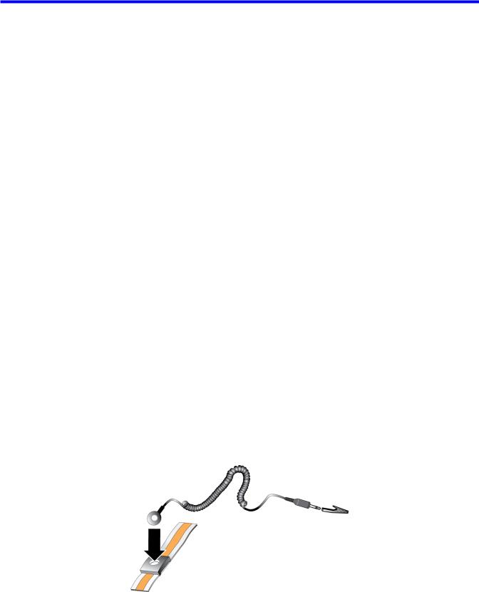
Protect your PS Series array from electrostatic discharge. When handling array hardware, use an electrostatic wrist strap or a similar form of protection. To use a wrist strap:
1. Connect the steel snap on the coil cord to the stud on the elastic band. See Figure 1.
Figure 1: Using an Electrostatic Wrist Strap
1
PS4210 Hardware Owner's Manual |
1 Basic Storage Array Information |
2.Fit the band tightly around your wrist.
3.Connect the band to ground. You can either plug the banana connector into a matching grounded receptacle, or attach it to the matching alligator clip and connect the clip to a grounded device. Examples of an appropriate ground would be an ESD mat or the metal frame of a grounded piece of equipment.
Array Bezel
The bezel is an optional trim panel that attaches to the front of the array to ensure the physical security of the array. You must remove the bezel to access and maintain the drives.
The bezel has a label that identifies the array model number.
Removing the Bezel
The steps for removing the bezel are the same for all array models:
1.Using the bezel key, unlock the bezel.
2.Holding the bezel, lift the latch on the left side of the bezel and swing the left side away from the array.
3.Lift the right side of the bezel off the right side of the array.
4.Set the bezel aside.
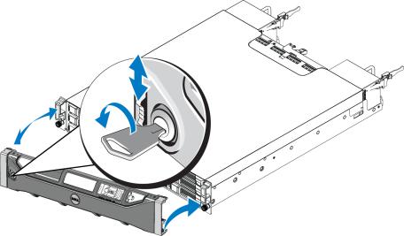
Installing the Bezel
The steps for installing the bezel are the same for all array models:
1.Hook the right end of the bezel onto the right side of the chassis.
2.Swing the left end of the bezel toward the left side of the chassis.
3.Press the bezel into place until the release latch closes.
4.Using the key provided, lock the bezel and store the key in a safe place as shown in Figure 2.
Figure 2: Installing the Bezel
2

PS4210 Hardware Owner's Manual |
1 Basic Storage Array Information |
Front-Panel Features and Indicators
The front of a PS4210, without the bezel, is shown in Figure 3.
Table 1 describes the front-panel features.
Figure 3: Front-Panel Features and Indicators (3.5-inch Drives)
Figure 4: Front Panel Features and Indicators (2.5-inch Drives)
|
|
|
|
Table 1: Front-Panel Feature Descriptions |
Item |
Indicator |
Icon |
Description |
|
|
|
|
The array status LED lights when the array power is on. |
|
|
|
|
• |
Off—No power. |
|
Array status |
|
• Steady blue—Array status is OK. |
|
1 |
|
• |
Slow blinking blue—Array status is Standby mode. |
|
LED |
|
• |
Blinking blue—Administrator request to identify the array (see the Group Manager |
|
|
|
|||
|
|
|
|
online help). |
|
|
|
• |
Steady amber—Critical status. |
|
|
|
• |
Blinking amber—Warning. |
|
|
|
The power LED is ON when at least one power supply is supplying power to the array. |
|
2 |
Power LED |
|
• Off—No power, or the array is in Standby mode. |
|
|
• Steady green—Array has at least one power supply providing power, and array is |
|||
|
|
|
||
|
|
|
|
not in Standby mode. |
3 |
Drive release |
None |
Enables you to remove a drive from the array. |
|
|
latch |
|
|
|
The LEDs are part of a built-in chassis control panel that is not hot-swappable and can be replaced only by support personnel. During the array power-up sequence, these LEDs will cycle through different states until the array is fully started and the active control module has been determined.
3
PS4210 Hardware Owner's Manual |
1 Basic Storage Array Information |
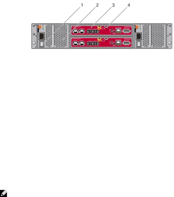
Back-Panel Features and Indicators
The back of a PS4210 is shown in Figure 5.
Table 2 describes the back-panel features.
Figure 5: Back-Panel Features
Table 2: Array Back-Panel Features
Item |
Feature |
Identifier |
Description |
|
|
|
|
|
|
1 |
Power switch |
None |
The power switch controls the power supply output to the array. One |
|
switch on each power supply. |
||||
|
|
|
||
|
|
|
|
|
2 |
Power supply unit |
PSU0 (left) |
Power supply and cooling fan module for array. |
|
(PSU) |
PSU1 (right) |
|||
|
|
|||
|
|
|
|
|
|
|
CM0 (top) |
The control module provides: |
|
3 |
Control module |
• Connection to a data path between the array and the applications |
||
CM1 (bottom) |
using the storage |
|||
|
|
|||
|
|
|
• Array management functions for your array |
|
4 |
Control module |
None |
Enables you to remove the control module from the array. |
|
release lever |
|
|||
|
|
|
||
|
|
|
|
Shutting Down and Restarting an Array
A PS Series array includes redundant, hot-swappable drives, power supplies, and control modules (in a dual control module array). You can remove a redundant component without affecting operation if a functioning component is available. Otherwise, Dell recommends that you cleanly shut down the array and turn off power before removing a component.
When an array is shut down, any volumes with data on the array will be set offline until the array is successfully restarted. Being offline affects initiators that are connected to the volumes.
Array shutdown procedure
1. Connect to the array in one of the following ways:
4
PS4210 Hardware Owner's Manual |
1 Basic Storage Array Information |
•Use telnet or SSH to connect to a functioning IP address assigned to a network interface on the array. Do not connect to the group IP address.
•Use the null modem cable, shipped with the array, to connect the serial port on the active control module (ACT LED is green) to a console or a computer running a terminal emulator.
Make sure the serial line characteristics are as follows:
•9600 baud
•One STOP bit
•No parity
•8 data bits
•No flow control
2.Log in to an account with read-write access, such as the grpadmin account.
3.Enter the shutdown command, as follows:
login: grpadmin
Password:
Welcome to Group Manager
Copyright 2001-2014 Dell Inc.
group1> shutdown
If you are using a serial connection to shut down an array, it is safe to turn off power when the “press any key” message appears. (Pressing any key will restart both control modules.)
If you are using a network connection, the session will be disconnected before the array is fully shut down. Confirm that the ACT LED on each control module is off (not lit) before turning off power to the array.
After performing array maintenance, you can turn on power to the array. When the array restart completes, the member and volumes will be set online.
5
PS4210 Hardware Owner's Manual |
1 Basic Storage Array Information |
6

2 Maintaining Drives
You can replace a failed drive while the array remains running.
About Drive Types
Depending on your configuration, your array supports up to 24 2.5-inch SAS and SSD drives or up to 12 3.5-inch SAS or NL-SAS drives in internal drive bays.
Drives are connected to a backplane through drive carriers and are hot-swappable.
Drives are supplied in a carrier that is keyed to fit into specific array models, and cannot be installed in other Dell arrays, or arrays not from Dell Inc.
Dell uses specially qualified and tested hard drives for its EqualLogic storage systems, and manages hard drive quality and firmware only for those drives. As a result, only Dell-provided hard drives are supported by PS Series arrays. Attempts to use other, unapproved hard drives in the PS4210 array will not be successful.
Identifying Failed Drives
A drive failure is indicated by:
•LEDs on the drive.
•A message on the console, in the event log, or in the Group Manager Alarms panel.
•Indications in the Group Manager Member Disks window or the CLI member select show disks command output.
Behind the bezel, arrays have a label showing the drive numbering for that specific array model:
•In arrays with 2.5-inch drives (installed vertically in a row), the drives are numbered 0–23, left to right.
•In arrays with 3.5-inch drives (installed horizontally), the drives are numbered from left to right and top to bottom, starting with 0 on the upper left side. Table 3 shows the drive order for the 3.5-inch drives.
Table 3: 3.5-inch Drive Numbering
0 |
1 |
2 |
3 |
4 |
5 |
6 |
7 |
8 |
9 |
10 |
11 |
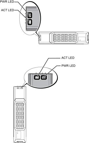
Interpreting Drive LEDs
The LEDs on a 3.5-inch drive are shown in Figure 6. The LEDs on a 2.5-inch drive are shown in Figure 7. Drive LED states are described in Table 4.
7
PS4210 Hardware Owner's Manual |
2 Maintaining Drives |
Figure 6: LEDs on 3.5-inch Drives
Figure 7: LEDs on 2.5-inch Drives
|
Table 4: Drive LED States |
|
Description |
|
Indicator States |
|
|
|
|
|
Blinking green: Drive is busy |
Drive activity indicator (ACT LED) |
|
Steady green: No drive activity |
|
|
Off: Drive is a spare, and spun down |
|
|
|
|
|
Green: Drive OK |
Drive status indicator (PWR LED) |
|
Amber: Drive failed |
|
|
Off: No power to drive |
|
|
|
Array Behavior When a Drive Fails
In firmware version 5.2.5 and later, Dell implemented a copy-to-spare operation to replace failing drives. This operation can, in many cases, improve the performance of the drive replacement process by avoiding a full RAID rebuild and as a result can provide better reliability.
 If a drive fails, replace it. Do not reinstall it in the array.
8
Loading...