


 Loading...
Installing Avaya Ethernet Routing Switch
3500 Series
Release 5.3.2
NN47203-304
Issue 01.02
September 2016
© 2015-2016, Avaya, Inc.
All Rights Reserved.
Notice
While reasonable efforts have been made to ensure that the information in this document is complete and accurate at the time of printing, Avaya assumes no liability for any errors. Avaya reserves the right to make changes and corrections to the information in this document without the obligation to notify any person or organization of such changes.
Documentation disclaimer
“Documentation” means information published in varying mediums which may include product information, operating instructions and performance specifications that are generally made available to users of products. Documentation does not include marketing materials. Avaya shall not be responsible for any modifications, additions, or deletions to the original published version of Documentation unless such modifications, additions, or deletions were performed by or on the express behalf of Avaya. End User agrees to indemnify and hold harmless Avaya, Avaya's agents, servants and employees against all claims, lawsuits, demands and judgments arising out of, or in connection with, subsequent modifications, additions or deletions to this documentation, to the extent made by End User.
Link disclaimer
Avaya is not responsible for the contents or reliability of any linked websites referenced within this site or Documentation provided by Avaya. Avaya is not responsible for the accuracy of any information, statement or content provided on these sites and does not necessarily endorse the products, services, or information described or offered within them. Avaya does not guarantee that these links will work all the time and has no control over the availability of the linked pages.
Warranty
Avaya provides a limited warranty on Avaya hardware and software. Refer to your sales agreement to establish the terms of the limited warranty. In addition, Avaya’s standard warranty language, as well as information regarding support for this product while under warranty is available to Avaya customers and other parties through the Avaya Support website: https://support.avaya.com/helpcenter/ getGenericDetails?detailId=C20091120112456651010 under the link “Warranty & Product Lifecycle” or such successor site as designated by Avaya. Please note that if You acquired the product(s) from an authorized Avaya Channel Partner outside of the United States and Canada, the warranty is provided to You by said Avaya Channel Partner and not by Avaya.
Licenses
THE SOFTWARE LICENSE TERMS AVAILABLE ON THE AVAYA
WEBSITE, HTTPS://SUPPORT.AVAYA.COM/LICENSEINFO, UNDER THE LINK “AVAYA SOFTWARE LICENSE TERMS (Avaya Products)” OR SUCH SUCCESSOR SITE AS DESIGNATED BY AVAYA, ARE APPLICABLE TO ANYONE WHO DOWNLOADS,
USES AND/OR INSTALLS AVAYA SOFTWARE, PURCHASED FROM AVAYA INC., ANY AVAYA AFFILIATE, OR AN AVAYA
CHANNEL PARTNER (AS APPLICABLE) UNDER A COMMERCIAL AGREEMENT WITH AVAYA OR AN AVAYA CHANNEL PARTNER. UNLESS OTHERWISE AGREED TO BY AVAYA IN WRITING, AVAYA DOES NOT EXTEND THIS LICENSE IF THE SOFTWARE WAS OBTAINED FROM ANYONE OTHER THAN AVAYA, AN AVAYA AFFILIATE OR AN AVAYA CHANNEL PARTNER; AVAYA RESERVES THE RIGHT TO TAKE LEGAL ACTION AGAINST YOU
AND ANYONE ELSE USING OR SELLING THE SOFTWARE WITHOUT A LICENSE. BY INSTALLING, DOWNLOADING OR USING THE SOFTWARE, OR AUTHORIZING OTHERS TO DO SO, YOU, ON BEHALF OF YOURSELF AND THE ENTITY FOR WHOM YOU ARE INSTALLING, DOWNLOADING OR USING THE SOFTWARE (HEREINAFTER REFERRED TO INTERCHANGEABLY AS “YOU” AND “END USER”), AGREE TO THESE TERMS AND CONDITIONS AND CREATE A BINDING CONTRACT BETWEEN YOU AND AVAYA INC. OR THE
APPLICABLE AVAYA AFFILIATE (“AVAYA”).
Avaya grants You a license within the scope of the license types described below, with the exception of Heritage Nortel Software, for which the scope of the license is detailed below. Where the order
documentation does not expressly identify a license type, the applicable license will be a Designated System License. The applicable number of licenses and units of capacity for which the license is granted will be one (1), unless a different number of licenses or units of capacity is specified in the documentation or other materials available to You. “Software” means computer programs in object code, provided by Avaya or an Avaya Channel Partner, whether as stand-alone products, pre-installed on hardware products, and any upgrades, updates, patches, bug fixes, or modified versions thereto. “Designated Processor” means a single stand-alone computing device. “Server” means a Designated Processor that hosts a software application to be accessed by multiple users. “Instance” means a single copy of the Software executing at a particular time: (i) on one physical machine; or (ii) on one deployed software virtual machine (“VM”) or similar deployment.
Licence types
Designated System(s) License (DS). End User may install and use each copy or an Instance of the Software only on a number of Designated Processors up to the number indicated in the order. Avaya may require the Designated Processor(s) to be identified in the order by type, serial number, feature key, Instance, location or other specific designation, or to be provided by End User to Avaya through electronic means established by Avaya specifically for this purpose.
Heritage Nortel Software
“Heritage Nortel Software” means the software that was acquired by Avaya as part of its purchase of the Nortel Enterprise Solutions Business in December 2009. The Heritage Nortel Software is the software contained within the list of Heritage Nortel Products located at https://support.avaya.com/LicenseInfo under the link “Heritage Nortel Products” or such successor site as designated by Avaya. For Heritage Nortel Software, Avaya grants Customer a license to use Heritage Nortel Software provided hereunder solely to the extent of the authorized activation or authorized usage level, solely for the purpose specified in the Documentation, and solely as embedded in, for execution on, or for communication with Avaya equipment. Charges for Heritage Nortel Software may be based on extent of activation or use authorized as specified in an order or invoice.
Copyright
Except where expressly stated otherwise, no use should be made of materials on this site, the Documentation, Software, Hosted Service, or hardware provided by Avaya. All content on this site, the documentation, Hosted Service, and the product provided by Avaya including the selection, arrangement and design of the content is owned either by Avaya or its licensors and is protected by copyright and other intellectual property laws including the sui generis rights relating to the protection of databases. You may not modify, copy, reproduce, republish, upload, post, transmit or distribute in any way any content, in whole or in part, including any code and software unless expressly authorized by Avaya. Unauthorized reproduction, transmission, dissemination, storage, and or use without the express written consent of Avaya can be a criminal, as well as a civil offense under the applicable law.
Third Party Components
“Third Party Components” mean certain software programs or portions thereof included in the Software or Hosted Service may contain software (including open source software) distributed under third party agreements (“Third Party Components”), which contain terms regarding the rights to use certain portions of the Software (“Third Party Terms”). As required, information regarding distributed Linux OS source code (for those products that have distributed Linux OS source code) and identifying the copyright holders of the Third
Party Components and the Third Party Terms that apply is available in the products, Documentation or on Avaya’s website at: https:// support.avaya.com/Copyright or such successor site as designated by Avaya. The open source software license terms provided as Third Party Terms are consistent with the license rights granted in these
Software License Terms, and may contain additional rights benefiting You, such as modification and distribution of the open source software. The Third Party Terms shall take precedence over these Software License Terms, solely with respect to the applicable Third Party Components to the extent that these Software License Terms impose greater restrictions on You than the applicable Third Party Terms.
Preventing Toll Fraud
“Toll Fraud” is the unauthorized use of your telecommunications system by an unauthorized party (for example, a person who is not a corporate employee, agent, subcontractor, or is not working on your company's behalf). Be aware that there can be a risk of Toll Fraud associated with your system and that, if Toll Fraud occurs, it can result in substantial additional charges for your telecommunications services.
Avaya Toll Fraud intervention
If You suspect that You are being victimized by Toll Fraud and You need technical assistance or support, call Technical Service Center Toll Fraud Intervention Hotline at +1-800-643-2353 for the United States and Canada. For additional support telephone numbers, see the Avaya Support website: https://support.avaya.com or such successor site as designated by Avaya.
Downloading Documentation
For the most current versions of Documentation, see the Avaya Support website: https://support.avaya.com, or such successor site as designated by Avaya.
Contact Avaya Support
See the Avaya Support website: https://support.avaya.com for product or Hosted Service notices and articles, or to report a problem with your Avaya product or Hosted Service. For a list of support telephone numbers and contact addresses, go to the Avaya Support website: https://support.avaya.com (or such successor site as designated by Avaya), scroll to the bottom of the page, and select Contact Avaya Support.
Trademarks
The trademarks, logos and service marks (“Marks”) displayed in this site, the Documentation, Hosted Service(s), and product(s) provided by Avaya are the registered or unregistered Marks of Avaya, its affiliates, its licensors, its suppliers, or other third parties. Users are not permitted to use such Marks without prior written consent from Avaya or such third party which may own the Mark. Nothing contained in this site, the Documentation, Hosted Service(s) and product(s) should be construed as granting, by implication, estoppel, or otherwise, any license or right in and to the Marks without the express written permission of Avaya or the applicable third party.
Avaya is a registered trademark of Avaya Inc.
All non-Avaya trademarks are the property of their respective owners.
Linux® is the registered trademark of Linus Torvalds in the U.S. and other countries.
Contents
Chapter 1: Introduction............................................................................................................ |
5 |
Purpose.................................................................................................................................. |
5 |
Chapter 2: New in this document............................................................................................ |
6 |
Chapter 3: Hardware compatibility for ERS 3500 Series....................................................... |
7 |
Switch models......................................................................................................................... |
7 |
Chapter 4: Preinstallation checklist...................................................................................... |
10 |
Chapter 5: Installing the Avaya Ethernet Routing Switch 3500 Series.............................. |
12 |
Installation checklist............................................................................................................... |
12 |
Installation fundamentals....................................................................................................... |
13 |
Front panel view.............................................................................................................. |
13 |
Electrostatic discharge........................................................................................................... |
15 |
Technical specifications......................................................................................................... |
16 |
Equipment requirement.......................................................................................................... |
19 |
Package contents............................................................................................................ |
19 |
Cable requirements......................................................................................................... |
22 |
Switch installation.................................................................................................................. |
22 |
Installing an ERS 3500 series switch in an equipment rack................................................. |
23 |
Installing an ERS 3510GT or ERS 3510GT-PWR+............................................................. |
24 |
Installation and removal of transceivers................................................................................... |
33 |
Installing an SFP............................................................................................................. |
33 |
Removing an SFP........................................................................................................... |
35 |
Stacking switches.................................................................................................................. |
35 |
Stacking capabilities........................................................................................................ |
36 |
Connecting switches in a stack......................................................................................... |
38 |
Connecting the AC power cord to the switch............................................................................ |
42 |
AC power specifications................................................................................................... |
43 |
Console port pin assignments................................................................................................ |
44 |
LED state definitions.............................................................................................................. |
45 |
Switch front panel LED views........................................................................................... |
45 |
Status LEDs.................................................................................................................... |
47 |
Chapter 6: Related Resources............................................................................................... |
49 |
Support................................................................................................................................ |
49 |
Documentation...................................................................................................................... |
49 |
Searching a documentation collection..................................................................................... |
50 |
Subscribing to e-notifications.................................................................................................. |
51 |
September 2016 |
Installing Avaya Ethernet Routing Switch 3500 Series |
4 |
Comments on this document? infodev@avaya.com

Chapter 1: Introduction
Purpose
This document provides conceptual information and installation procedures for the switch hardware.
September 2016 |
Installing Avaya Ethernet Routing Switch 3500 Series |
5 |
Comments on this document? infodev@avaya.com
Chapter 2: New in this document
Installing Avaya Ethernet Routing Switch 3500 Series, NN47203–304 is a new document.
September 2016 |
Installing Avaya Ethernet Routing Switch 3500 Series |
6 |
Comments on this document? infodev@avaya.com
Chapter 3: Hardware compatibility for ERS 3500 Series
This chapter lists the ERS 3500 Series hardware.
Switch models
The following table describes the ERS 3500 series models.
All switch models support autopolarity.
|
Model |
Part Number |
Description |
|
ERS 3510GT |
AL3500?04– |
10 port Ethernet Switch configured as: |
|
|
E6 |
• 8 ports of 10/100/1000BASE-T with 2 |
|
|
|
|
|
|
|
SFP ports |
|
|
|
• Fanless operation |
|
|
|
• Standalone |
|
|
|
|
|
ERS 3510GT-PWR+ |
AL3500?14– |
10 port Ethernet Switch configured as: |
|
|
E6 |
• 8 ports of 10/100/1000BASE-T |
|
|
|
|
|
|
|
(support for IEEE 802.3af PoE or IEEE |
|
|
|
802.3at PoE+) with 2 SFP ports |
|
|
|
• Dual power modes - fanless operation |
|
|
|
in Low Power Budget mode at 60W |
|
|
|
max PoE budget, or normal fan |
|
|
|
operation in High Power Budget mode |
|
|
|
at 170W max PoE budget |
|
|
|
• Standalone |
|
ERS 3524GT |
AL3500?05– |
24 port Ethernet Switch configured as: |
|
|
E6 |
• 24 ports of 10/100/1000BASE-T with 4 |
|
|
|
|
|
|
|
shared SFP ports (combo with ports |
|
|
|
21-24) |
|
|
|
• 2 rear SFP ports can be used as |
|
|
|
additional ports in Standalone Mode or |
|
|
|
Table continues… |
September 2016 |
Installing Avaya Ethernet Routing Switch 3500 Series |
7 |
Comments on this document? infodev@avaya.com

Hardware compatibility for ERS 3500 Series
|
Model |
Part Number |
Description |
|
|
|
2 rear HiStack ports delivering up to |
|
|
|
10Gbps Full Duplex (FDX) of |
|
|
|
Stackable Chassis throughput per |
|
|
|
switch in Stacking Mode |
|
|
|
|
|
ERS 3524GT-PWR+ |
AL3500?15– |
24 port Ethernet Switch configured as: |
|
|
E6 |
• 24 ports of 10/100/1000BASE-T |
|
|
|
|
|
|
|
(support for IEEE 802.3af PoE or IEEE |
|
|
|
802.3at PoE+) with 4 shared SFP |
|
|
|
ports (combo with ports 21-24) |
|
|
|
• 2 rear SFP ports can be used as |
|
|
|
additional ports in Standalone Mode or |
|
|
|
as 2 rear HiStack ports delivering up to |
|
|
|
10Gbps (FDX) of Stackable Chassis |
|
|
|
throughput per switch in Stacking |
|
|
|
Mode |
|
ERS 3526T |
AL3500?01– |
26 port Ethernet Switch can be |
|
|
E6 |
configured as: |
|
|
|
• 24 ports of 10/100Base-TX, plus 2 |
|
|
|
combo 10/100/1000BASE-T or SFP |
|
|
|
ports |
|
|
|
• 2 rear SFP ports can be used as |
|
|
|
additional ports in Standalone Mode or |
|
|
|
2 rear HiStack ports delivering up to |
|
|
|
10Gbps (FDX) of Stackable Chassis |
|
|
|
throughput per switch in Stacking |
|
|
|
Mode |
|
|
|
• Fanless operation |
|
|
|
|
|
ERS 3526T-PWR+ |
AL3500?11– |
26 port Ethernet Switch can be |
|
|
E6 |
configured as: |
|
|
|
• 24 ports of 10/100BASE-TX (support |
|
|
|
for IEEE 802.3af PoE or IEEE 802.3at |
|
|
|
PoE+), plus 2 combo |
|
|
|
10/100/1000BASE-T or SFP ports |
|
|
|
• Rear SFP ports can be used as |
|
|
|
additional ports in Standalone Mode or |
|
|
|
2 rear HiStack ports delivering up to |
|
|
|
10Gbps (FDX) of Stackable Chassis |
|
|
|
throughput per switch in Stacking |
|
|
|
Mode |
|
ERS 3549GTS |
AL3500?06-E6 |
49 port Ethernet Switch configured as: |
|
|
|
• 48 ports of 10/100/1000BASE-T with 2 |
|
|
|
shared SFP ports (combo with ports |
|
|
|
47-48) |
|
|
|
Table continues… |
September 2016 |
Installing Avaya Ethernet Routing Switch 3500 Series |
8 |
Comments on this document? infodev@avaya.com

Switch models
Model |
Part Number |
Description |
|
|
• 1 SFP+ (1Gig or 10Gig) uplink port |
|
|
• 2 rear SFP ports can be used as |
|
|
additional ports in Standalone Mode or |
|
|
2 rear HiStack ports delivering up to |
|
|
10Gbps (FDX) of Stackable Chassis |
|
|
throughput per switch in Stacking |
|
|
Mode |
|
|
|
ERS 3549GTS-PWR+ |
AL3500?16-E6 |
49 port Ethernet Switch configured as: |
|
|
• 48 ports of 10/100/1000BASE-T |
|
|
(support for IEEE 802.3af PoE or IEEE |
|
|
802.3at PoE+) with 2 shared SFP |
|
|
ports (combo with ports 47-48) |
|
|
• 1 SFP+ (1Gig or 10Gig) uplink port |
|
|
• 2 rear SFP ports can be used as |
|
|
additional ports in Standalone Mode or |
|
|
2 rear HiStack ports delivering up to |
|
|
10Gbps (FDX) of Stackable Chassis |
|
|
throughput per switch in Stacking |
|
|
Mode |
ERS 3550T |
AL3500?07-E6 |
• 48 ports of 10/100 Ethernet |
|
|
• 2 ports of combo 10/100/1000/SFP |
|
|
• 2 ports of rear dual mode / stacking |
|
|
|
ERS 3550T-PWR+ |
AL3500?17-E6 |
• 48 ports of 10/100 Ethernet 802.3at |
|
|
PoE+ |
|
|
• 2 ports of combo 10/100/1000/SFP |
|
|
• 2 ports of rear dual mode / stacking |
|
|
|
Question marks (?) in the table above signify power cord types; substitute the following regional variants:
•A — no power cord
•B — EU power cord
•C — UK / Ireland power cord
•D — Japan power cord
•E — North American power cord
•F — Australia / New Zealand / China power cord
September 2016 |
Installing Avaya Ethernet Routing Switch 3500 Series |
9 |
Comments on this document? infodev@avaya.com

Chapter 4: Preinstallation checklist
Before you install the Avaya Ethernet Routing Switch 3500 Series, make sure that you complete the tasks in the preinstallation checklist.
|
No. |
Task |
Description |
|
|
|
|
|
|
|
1. |
Review the technical specification for |
For the physical, electrical, and |
|
|
|
the switch. Make sure that the area |
environmental specifications, see |
|
|
|
where you install the switch and |
Technical specifications on page 16. |
|
|
|
where it will operate meet the |
|
|
|
|
requirements. |
|
|
|
|
|
|
|
|
2. |
Verify the AC power specifications. |
See AC power specifications on |
|
|
|
Optionally order a redundant Power |
page 43. |
|
|
|
Supply Unit (PSU) to provide |
|
|
|
|
redundancy and load sharing. |
|
|
|
3. |
Make sure that you have the |
See Cable requirements on page 22. |
|
|
|
following tools and cables: |
|
|
|
|
• Phillips #2 screwdriver RJ-45 |
|
|
|
|
console port cable |
|
|
|
|
• ESD cable |
|
|
|
|
|
|
|
|
4. |
Unpack the equipment. |
Observe ESD precautions when you |
|
|
|
|
unpack the equipment. See Electrostatic |
|
|
|
|
discharge on page 15. |
|
|
5. |
Verify the contents of the shipped |
See Package contents on page 19 for |
|
|
|
package. |
a description of the components that are |
|
|
|
|
provided with the switch. |
|
|
|
|
|
|
|
6. |
Make sure that the power cord has |
See AC power cord specifications on |
|
|
|
the correct country-specific |
page 43. |
|
|
|
termination. |
|
|
|
7. |
Depending on the switch model, |
If the switch model is ERS 3510GT or |
|
|
|
prepare the shelf or table or prepare |
ERS 3510 GT PWR+, prepare shelf or |
|
|
|
the equipment rack. |
table and ensure the surface supports |
|
|
|
|
the combined weight of the switch and |
|
|
|
|
attached cables from 15 and 20 pounds |
|
|
|
|
(7 to 9 kilograms). |
|
|
|
|
Table continues… |
|
September 2016 |
Installing Avaya Ethernet Routing Switch 3500 Series |
10 |
Comments on this document? infodev@avaya.com
No. |
Task |
Description |
|
|
|
|
|
|
|
See Installing ERS 3510GT or ERS |
|
|
|
3510GT PWR+ on a table or shelf on |
|
|
|
page 25. |
|
|
|
Optionally, prepare the rack. See |
|
|
|
Installing a single ERS 3510GT or ERS |
|
|
|
3510GT-PWR+ switch in an equipment |
|
|
|
rack on page 27 or Installing two ERS |
|
|
|
3510GT or ERS 3510GT-PWR+ |
|
|
|
switches in an equipment rack on |
|
|
|
page 29. |
|
|
|
|
|
|
|
For the other switch models in ERS |
|
|
|
3500 series, prepare the equipment rack |
|
|
|
and ensure that there is enough rack |
|
|
|
space of 1.75 inches (4.45 centimeters). |
|
|
|
See Installing ERS 3500 in an |
|
|
|
equipment rack on page 23. |
|
|
|
|
|
September 2016 |
Installing Avaya Ethernet Routing Switch 3500 Series |
11 |
Comments on this document? infodev@avaya.com

Chapter 5: Installing the Avaya Ethernet
Routing Switch 3500 Series
This chapter provides the information and procedures to install the Avaya Ethernet Routing Switch 3500 Series.
Installation checklist
Use this checklist to install the Avaya Ethernet Routing Switch.
Table 1: Installation checklist
No. |
Task |
Description |
|
|
|
|
|
|
|
1. |
Install the switch. |
Do any one of the following: |
|
|
|
Installation depends on the switch |
• Installing ERS 3500 in an equipment |
|
|
|
model. ERS 3510T or ERS 3510GT- |
|
rack on page 23 |
|
|
PWR+ can be mounted on a wall, |
• |
Installing ERS 3510GT or ERS |
|
|
table, or shelf. Optionally, it can also |
|
||
|
|
3510GT PWR+ on a table or shelf on |
|
|
|
be mounted in an equipment rack. |
|
|
|
|
|
page 25 |
|
|
|
All the other switches in the ERS |
|
|
|
|
• |
Installing a single ERS 3510GT or |
|
|
|
3500 Series are installed in an |
|
||
|
|
ERS 3510GT-PWR+ switch in an |
|
|
|
equipment rack. |
|
|
|
|
|
equipment rack on page 27 |
|
|
|
|
|
|
|
|
|
• |
Installing two ERS 3510GT or ERS |
|
|
|
|
3510GT-PWR+ switches in an |
|
|
|
|
equipment rack on page 29 |
|
|
|
|
|
|
2. |
Connect the AC power cord to the |
See, Connecting the AC power cord to |
|
|
|
switch. |
the switch on page 42. |
|
|
3. |
Check LEDs to verify the installation. |
See, LED state definitions on page 45. |
|
|
|
|
|
|
|
4. |
(Optional) Connect the switches in a |
See, Connecting the switches in a |
|
|
|
stack. |
stack on page 38. |
|
|
|
|
|
|
|
September 2016 |
Installing Avaya Ethernet Routing Switch 3500 Series |
12 |
Comments on this document? infodev@avaya.com

Installation fundamentals
Installation fundamentals
This section provides information about the switches and their front panel view.
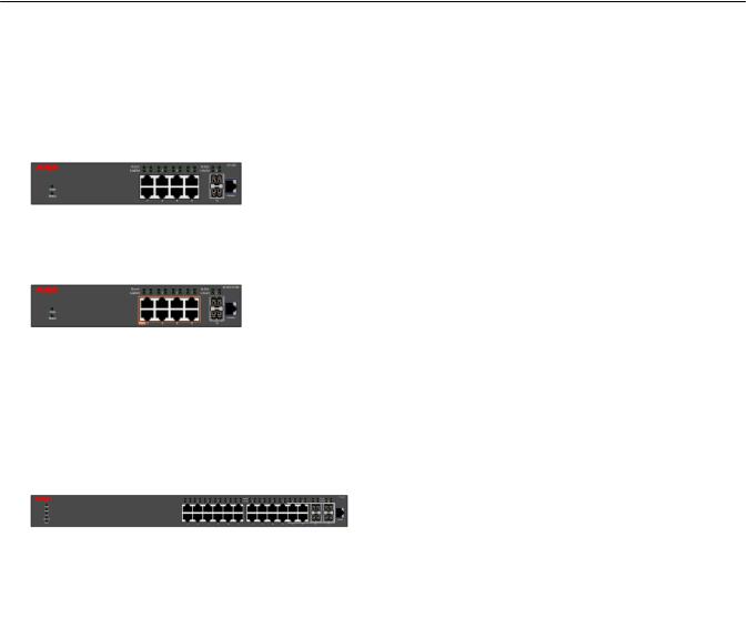
Front panel view
The following figures illustrate the front panel ports for the switch series.
September 2016 |
Installing Avaya Ethernet Routing Switch 3500 Series |
13 |
Comments on this document? infodev@avaya.com

Installing the Avaya Ethernet Routing Switch 3500 Series
Figure 1: ERS 3500 series front panel port illustrations
September 2016 |
Installing Avaya Ethernet Routing Switch 3500 Series |
14 |
Comments on this document? infodev@avaya.com

Electrostatic discharge
Table 2: Key
Item |
Description |
1 |
Console RJ45 port |
|
|
2 |
1000Base-X SFP ports |
3 |
10/100 RJ45 ports |
|
|
4 |
10/100 RJ45 PoE+ ports |
5 |
10/100/1000 RJ45 ports |
|
|
6 |
10/100/1000 RJ45 PoE+ ports |
7 |
SFP+ for SFP+ port |
|
|
Electrostatic discharge
This section provides information and procedures to prevent electrostatic discharge during installation.
Preventing electrostatic discharge damage
Electrostatic discharge (ESD) is a discharge of stored static electricity that can damage equipment and impair electrical circuitry. Electrostatic voltages can result from friction including, pulling cabling through conduits, walking across carpeted areas, and building static charge in clothing. When you improperly handle electronic components, ESD damage occurs and can result in complete or intermittent failures. While networking equipment is commonly designed and tested to withstand common mode ESD events, voltage can sometimes discharge to some connector pins, which can potentially damage the networking equipment.
 Caution:
To protect the switch against ESD damage, take the following measures before you connect data cables to the device:
•Always use antistatic wrist straps. Make sure you adjust the strap to provide good skin contact.
•Ensure that you properly ground work surfaces and equipment racks for protection against electrostatic discharge. You must connect the common point to the building ground wire. In a properly wired building, the nearest reliable ground is typically at the electrical outlet.
•Avoid contact between equipment and clothing. The wrist or ankle strap protects only the equipment from ESD voltages on the body; ESD voltages on clothing can still cause damage.
•Avoid touching any connector pins.
•Do not remove the wrist or ankle strap until the installation is complete.
September 2016 |
Installing Avaya Ethernet Routing Switch 3500 Series |
15 |
Comments on this document? infodev@avaya.com
Installing the Avaya Ethernet Routing Switch 3500 Series
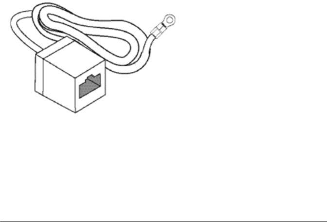
Preventing electrostatic damage in new cable installations
With new cable installations, Avaya recommends that you use an ESD discharge cable to reduce the potential for damage from static, that can build up in cables. The following figure illustrates an ESD cable.
Figure 2: ESD discharge cable
To install the ESD discharge cable, perform this procedure.
1.Connect the ground lug on the ESD discharge cable to a safe and suitable earth ground.
2.Connect all RJ-45 cable connectors to the female RJ-45 connector of the ESD discharge cable for at least 5 seconds, and then connect each RJ-45 cable connector to the switch.
3.Leave cables connected to the networking equipment. After you connect cables to networking equipment, the cables do not build up charge.
Technical specifications
The following table provides the technical specifications for the individual switches in the Avaya Ethernet Routing Switch 3500 Series. Ensure that the area where you install the switch and where it operates meets these requirements.
 Warning:
To avoid bodily injury from hazardous electrical shock and current, never remove the top of the device. No user-serviceable components are inside.
September 2016 |
Installing Avaya Ethernet Routing Switch 3500 Series |
16 |
Comments on this document? infodev@avaya.com

|
|
|
Technical specifications |
|
Table 3: Physical specifications |
|
|
|
|
|
|
|
|
Switch |
Specification |
|
Height |
ERS 3526T, ERS 3526T-PWR+, |
1U or 44.5mm / 1.75" |
|
|
ERS 3510GT, ERS 3510GT-PWR |
|
|
|
+, ERS 3524GT, ERS 3524GT- |
|
|
|
PWR+, ERS 3549GTS, and ERS |
|
|
|
3549GTS-PWR+ |
|
|
|
|
|
|
Width |
ERS 3526T, ERS 3526T-PWR+, |
440mm / 17.5" |
|
|
ERS 3524GT, ERS 3524GT-PWR |
|
|
|
+, ERS 3549GTS ERS and |
|
|
|
3549GTS-PWR+ |
|
|
|
ERS 3510GT, ERS 3510GT-PWR |
220mm / 8.75" |
|
|
+ |
|
|
|
|
|
|
|
ERS 3526T, ERS 3526T-PWR+, |
280mm / 11" |
|
|
ERS 3510GT-PWR+, ERS |
|
|
|
3524GT, and ERS 3524GT-PWR+ |
|
|
|
ERS 3510GT |
200mm / 8" |
|
|
|
|
|
|
ERS 3549GTS and ERS |
405mm / 15.75" |
|
|
3549GTS-PWR+ |
|
|
Weight |
ERS 3526T |
3.60kg / 8lb |
|
|
|
|
|
|
ERS 3526T-PWR+ |
4.50kg / 10lb |
|
|
ERS 3510GT |
1.75kg / 3.9lb |
|
|
|
|
|
|
ERS 3510GT-PWR+ |
2.70kg / 6lb |
|
|
ERS 3524GT |
3.55kg / 7.8lb |
|
|
|
|
|
|
ERS 3524GT-PWR+ |
4.61kg / 10.2lb |
|
|
ERS 3549GTS and ERS |
6.15kg / 13.55lb |
|
|
3549GTS-PWR+ |
|
|
|
|
|
|
|
ERS 3510GT |
1.75 kg / 3.85 lb |
|
|
ERS 3510GT-PWR+ |
2.70 kg / 5.9 lb |
|
|
|
|
|
Table 4: Electrical specifications |
|
|
|
|
|
|
|
Electrical component |
Switch details |
Specification |
|
Power consumption |
ERS 3526T |
28.5 Watts max |
|
|
|
|
|
|
ERS 3526T-PWR+ |
500 Watts max |
|
|
ERS 3510GT |
18 Watts max |
|
|
|
|
|
|
ERS 3510GT-PWR+ |
210 Watts |
|
|
ERS 3524GT |
28.5 Watts max |
|
|
|
|
|
|
ERS 3524GT-PWR+ |
500 Watts max |
|
|
ERS 3549GTS |
65 Watts max |
|
|
|
|
|
|
|
Table continues… |
September 2016 |
Installing Avaya Ethernet Routing Switch 3500 Series |
17 |
Comments on this document? infodev@avaya.com
Loading...