


White Electronic Designs WSF128K32-27H2I, WSF128K32-27H2CA, WSF128K32-27H2C, WSF128K32-22H2MA, WSF128K32-22H2M Datasheet
...White Electronic Designs |
|
WSF128K32-XH2X |
128KX32 SRAM/FLASH MODULE PRELIMINARY* |
|
|
FEATURES
■Access Times of 25ns (SRAM) and 70, 90 and 120ns (FLASH)
■Packaging:
•66-pin, PGAType, 1.385 inch square HIP, Hermetic Ceramic HIP (Package 402)
■128Kx32 SRAM
■128Kx32 5V Flash
■Organized as 128Kx32 of SRAM and 128Kx32 of Flash Memory with common Data Bus
■Low Power CMOS
■Commercial,IndustrialandMilitaryTemperatureRanges
■TTL Compatible Inputs and Outputs
■Built-in Decoupling Caps and Multiple Ground Pins for Low Noise Operation
■Weight - 13 grams typical
FLASH MEMORY FEATURES
■10,000 Erase/Program Cycles
■Sector Architecture
•8 equal size sectors of 16K bytes each
•Any combination of sectors can be concurrently erased. Also supports full chip erase
■5 Volt Programming; 5V ± 10% Supply
■Embedded Erase and Program Algorithms
■Hardware Write Protection
■Page Program Operation and Internal Program Control Time.
* This data sheet describes a product under development, not fully characterized, and is subject to change without notice.
Note: Programming information available upon request.
FIG. 1 PIN CONFIGURATION FOR WSF128K32-XH2X
|
|
|
TOP VIEW |
|
|
|
|
PIN DESCRIPTION |
|||
1 |
12 |
23 |
|
34 |
45 |
|
56 |
|
D0-31 |
Data Inputs/Outputs |
|
|
|
|
|
|
|
|
|
|
|||
|
I/O8 |
FWE2 |
I/O15 |
I/O24 |
VCC |
I/O31 |
|
|
A0-16 |
Address Inputs |
|
|
I/O9 |
SWE2 |
I/O14 |
I/O25 |
SWE4 |
I/O30 |
|
|
SWE1-4 SRAM Write Enables |
||
|
|
|
SCS |
SRAM Chip Select |
|||||||
|
|
|
|
|
|
|
|
|
|||
|
I/O10 |
GND |
I/O13 |
I/O26 |
FWE4 |
I/O29 |
|
|
OE |
Output Enable |
|
|
|
|
|
|
|
|
|
|
VCC |
Power Supply |
|
|
A14 |
I/O11 |
I/O12 |
A7 |
I/O27 |
I/O28 |
|
|
GND |
|
Ground |
|
|
|
|
|
|
|
|
|
|
||
|
A16 |
A10 |
OE |
A12 |
A4 |
A1 |
|
|
NC |
Not Connected |
|
|
|
|
FWE1-4 Flash Write Enables |
||||||||
|
|
|
|
|
|
|
|
|
|||
|
A11 |
A9 |
NC |
SWE1 |
A5 |
A2 |
|
|
FCS |
Flash Chip Select |
|
|
A0 |
A15 |
FWE1 |
A13 |
A6 |
A3 |
|
|
|
|
|
|
NC |
VCC |
I/O7 |
A8 |
FWE3 |
I/O23 |
|
BLOCK DIAGRAM |
|
|
|
|
|
|
|
|
|
||||||
|
I/O0 |
FCS |
I/O6 |
I/O16 |
SWE3 |
I/O22 |
FWE1 SWE1 |
FWE2 SWE2 |
FWE3 |
SWE3 |
FWE4 SWE4 |
|
|
|
|
|
|
|
OE |
|
|
|
|
|
|
|
|
|
|
|
A0-16 |
|
|
|
|
|
I/O1 |
SCS |
I/O5 |
I/O17 |
GND |
I/O21 |
SCS |
|
|
|
|
|
|
|
|
|
|
|
FCS |
|
|
|
|
|
I/O2 |
I/O3 |
I/O4 |
I/O18 |
I/O19 |
I/O20 |
128K x 8 Flash |
128K x 8 Flash |
128K x 8 Flash |
|
128K x 8 Flash |
|
|
|
|
|
|
|
128K x 8 SRAM |
128K x 8 SRAM |
128K x 8 SRAM |
128K x 8 SRAM |
|
11 |
22 |
33 |
|
44 |
55 |
|
66 |
|
|
|
|
|
|
|
|
|
|
|
I/O0-7 |
I/O8-15 |
I/O16-23 |
I/O24-31 |
|
October 2002 Rev. 4 |
1 |
White Electronic Designs Corporation • (602) 437-1520 • www.whiteedc.com |
|
|

White Electronic Designs |
WSF128K32-XH2X |
ABSOLUTE MAXIMUM RATINGS
Parameter |
Symbol |
Min |
|
Max |
Unit |
|
|
|
|
|
|
|
|
Operating Temperature |
TA |
-55 |
|
+125 |
°C |
|
Storage Temperature |
TSTG |
-65 |
|
+150 |
°C |
|
Signal Voltage Relative to GND |
VG |
-0.5 |
|
7.0 |
V |
|
Junction Temperature |
TJ |
|
|
150 |
°C |
|
Supply Voltage |
VCC |
-0.5 |
|
7.0 |
V |
|
|
|
|
|
|
|
|
|
|
|
|
|
|
|
Parameter |
|
|
|
|
|
|
|
|
|
|
|
|
|
Flash Data Retention |
|
|
|
10 years |
|
|
Flash Endurance (write/erase cycles) |
|
|
10,000 |
|
||
NOTE:
1. Stresses above the absolute maximum rating may cause permanent damage to the device. Extended operation at the maximum levels may degrade performance and affect reliability.
RECOMMENDED OPERATING CONDITIONS
Parameter |
Symbol |
Min |
Max |
Unit |
|
|
|
|
|
Supply Voltage |
VCC |
4.5 |
5.5 |
V |
|
|
|
|
|
Input High Voltage |
VIH |
2.2 |
VCC + 0.3 |
V |
Input Low Voltage |
VIL |
-0.5 |
+0.8 |
V |
SRAM TRUTH TABLE
|
|
|
|
|
|
|
|
|
|
|
|
SCS |
OE |
SWE |
Mode |
Data I/O |
Power |
||||||
|
H |
|
X |
|
X |
Standby |
High Z |
Standby |
|||
|
L |
|
L |
|
H |
Read |
Data Out |
Active |
|||
|
L |
|
H |
|
H |
Read |
High Z |
Active |
|||
|
L |
|
X |
|
L |
Write |
Data In |
Active |
|||
NOTE:
1. FCS must remain high when SCS is low.
CAPACITANCE
(TA = +25°C)
|
Test |
Symbol |
Condition |
Max |
Unit |
|||||
|
|
|
|
|
|
|
|
|
|
|
|
OE Capacitance |
COE |
VIN = 0V, f = 1.0MHz |
80 |
pF |
|||||
|
|
|
|
|
|
|
|
|
|
|
|
F/S WE 1-4 Capacitance |
CWE |
VIN = 0V, f = 1.0MHz |
30 |
pF |
|||||
|
|
|
|
|
|
|
|
|||
|
F/S CS Capacitance |
CCS |
VIN = 0V, f = 1.0MHz |
50 |
pF |
|||||
|
D0-31 Capacitance |
CI/O |
VIN = 0V, f = 1.0MHz |
30 |
pF |
|||||
|
A0 - A16 Capacitance |
CAD |
VIN = 0V, f = 1.0MHz |
80 |
pF |
|||||
|
|
|
|
|
|
|
|
|
|
|
This parameter is guaranteed by design but not tested.
DC CHARACTERISTICS
(VCC = 5.0V, VSS = 0V, TA = -55°C TO +125°C)
Parameter |
Symbol |
Conditions |
Min |
Max |
Unit |
|||||||||||||||||||||||
Input Leakage Current |
ILI |
|
VCC = 5.5, VIN = GND to VCC |
|
10 |
µA |
||||||||||||||||||||||
|
|
|
|
|
|
|
|
|
|
|
|
|
|
|
|
|
|
|
|
|
|
|
|
|
|
|
|
|
|
|
|
|
|
|
|
|
|
|
|
|
|
|
|
|
|
|
|
||||||||||
Output Leakage Current |
ILO |
|
|
|
SCS |
|
|
= VIH, OE = VIH, VOUT = GND to VCC |
|
10 |
µA |
|||||||||||||||||
|
|
|
|
|
|
|
|
|
|
|
|
|
|
|
|
|
|
|
|
|
|
|
|
|
|
|
|
|
SRAM Operating Supply Current x 32 Mode |
ICCx32 |
|
|
|
|
|
|
|
|
= VIL, |
|
|
|
|
|
= |
|
|
|
= VIH, f = 5MHz, VCC = 5.5 |
|
670 |
mA |
|||||
|
|
|
|
SCS |
|
|
|
|
OE |
|
FCS |
|
||||||||||||||||
|
|
|
|
|
|
|
|
|
|
|
|
|
|
|
|
|
|
|
|
|
|
|
|
|
|
|
|
|
|
|
|
|
|
|
|
|
|
|
|
|
|
|
|
|
|
|
|
|
|
|
|
|
|
||||
Standby Current |
ISB |
|
|
FCS |
= SCS = VIH, OE = VIH, f = 5MHz, VCC = 5.5 |
|
80 |
mA |
||||||||||||||||||||
|
|
|
|
|
|
|
|
|
|
|
|
|
|
|
|
|
|
|
|
|
|
|
|
|
|
|
|
|
SRAM Output Low Voltage |
VOL |
|
IOL = 8mA, VCC = 4.5 |
|
0.4 |
V |
||||||||||||||||||||||
|
|
|
|
|
|
|
|
|
|
|
|
|
|
|
|
|
|
|
|
|
|
|
|
|
|
|
|
|
SRAM Output High Voltage |
VOH |
|
IOH = -4.0mA, VCC = 4.5 |
2.4 |
|
V |
||||||||||||||||||||||
|
|
|
|
|
|
|
|
|
|
|
|
|
|
|
|
|
|
|
|
|
|
|
|
|
|
|
|
|
Flash VCC Active Current for Read (1) |
ICC1 |
|
|
|
|
|
|
|
|
|
= |
|
|
= VIH |
|
220 |
mA |
|||||||||||
|
|
FCS |
= VIL, |
OE |
|
SCS |
|
|||||||||||||||||||||
|
|
|
|
|
|
|
|
|
|
|
|
|
|
|
|
|
|
|
|
|
|
|
|
|
|
|
|
|
|
|
|
|
|
|
|
|
|
|
|
|
|
|
|
|
|
|
|
|
|
|
|||||||
Flash VCC Active Current for Program or |
ICC2 |
|
FCS = VIL, OE = SCS = VIH |
|
280 |
mA |
||||||||||||||||||||||
Erase (2) |
|
|
|
|
|
|
|
|
|
|
|
|
|
|
|
|
|
|
|
|
|
|
|
|
|
|
|
|
|
|
|
|
|
|
|
|
|
|
|
|
|
|
|
|
|
|
|
|
|
|
|
|
|
|
|
|
|
Flash Output Low Voltage |
VOL |
|
IOL = 8.0mA, VCC = 4.5 |
|
0.45 |
V |
||||||||||||||||||||||
|
|
|
|
|
|
|
|
|
|
|
|
|
|
|
|
|
|
|
|
|
|
|
|
|
|
|
|
|
Flash Output High Voltage |
VOH1 |
|
IOH = -2.5 mA, VCC = 4.5 |
0.85 x VCC |
|
V |
||||||||||||||||||||||
|
|
|
|
|
|
|
|
|
|
|
|
|
|
|
|
|
|
|
|
|
|
|
|
|
|
|
|
|
Flash Output High Voltage |
VOH2 |
|
IOH = -100 µA, VCC = 4.5 |
VCC -0.4 |
|
V |
||||||||||||||||||||||
|
|
|
|
|
|
|
|
|
|
|
|
|
|
|
|
|
|
|
|
|
|
|
|
|
|
|
|
|
Flash Low VCC Lock Out Voltage |
VLKO |
|
|
|
|
|
|
|
|
|
|
|
|
|
|
|
|
|
|
|
|
|
|
|
|
3.2 |
|
V |
|
|
|
|
|
|
|
|
|
|
|
|
|
|
|
|
|
|
|
|
|
|
|
|
|
|
|
|
|
NOTES:
1.The ICC current listed includes both the DC operating current and the frequency dependent component (@ 5 MHz). The frequency component typically is less than 2 mA/MHz, with OE at VIH.
2.ICC active while Embedded Algorithm (program or erase) is in progress.
3.DC test conditions: VIL = 0.3V, VIH = VCC - 0.3V
White Electronic Designs Corporation • Phoenix AZ • (602) 437-1520 |
2 |
White Electronic Designs |
WSF128K32-XH2X |
SRAM AC CHARACTERISTICS
(VCC = 5.0V, TA = -55°C TO +125°C)
Parameter |
|
Symbol |
-25 |
|
Unit |
|
Read Cycle |
|
|
Min |
Max |
|
|
Read Cycle Time |
|
tRC |
25 |
|
|
ns |
Address Access Time |
|
tAA |
|
|
25 |
ns |
Output Hold from Address Change |
|
tOH |
0 |
|
|
ns |
Chip Select Access Time |
|
tACS |
|
|
25 |
ns |
Output Enable to Output Valid |
|
tOE |
|
|
15 |
ns |
Chip Select to Output in Low Z |
|
tCLZ1 |
3 |
|
|
ns |
Output Enable to Output in Low Z |
|
tOLZ1 |
0 |
|
|
ns |
Chip Disable to Output in High Z |
|
tCHZ1 |
|
|
12 |
ns |
Output Disable to Output in High Z |
|
tOHZ1 |
|
|
12 |
ns |
|
|
|
||||
1. This parameter is guaranteed by design but not tested.
SRAM AC CHARACTERISTICS
(VCC = 5.0V, TA = -55°C TO +125°C)
Parameter |
Symbol |
|
-25 |
Unit |
|
Write Cycle |
|
Min |
|
Max |
|
Write Cycle Time |
tWC |
25 |
|
|
ns |
Chip Select to End of Write |
tCW |
20 |
|
|
ns |
Address Valid to End of Write |
tAW |
20 |
|
|
ns |
Data Valid to End of Write |
tDW |
15 |
|
|
ns |
Write Pulse Width |
tWP |
20 |
|
|
ns |
Address Setup Time |
tAS |
0 |
|
|
ns |
Address Hold Time |
tAH |
0 |
|
|
ns |
Output Active from End of Write |
tOW1 |
3 |
|
|
ns |
Write Enable to Output in High Z |
tWHZ1 |
|
|
15 |
ns |
Data Hold from Write Time |
tDH |
0 |
|
|
ns |
|
|
|
|
|
|
1. This parameter is guaranteed by design but not tested.
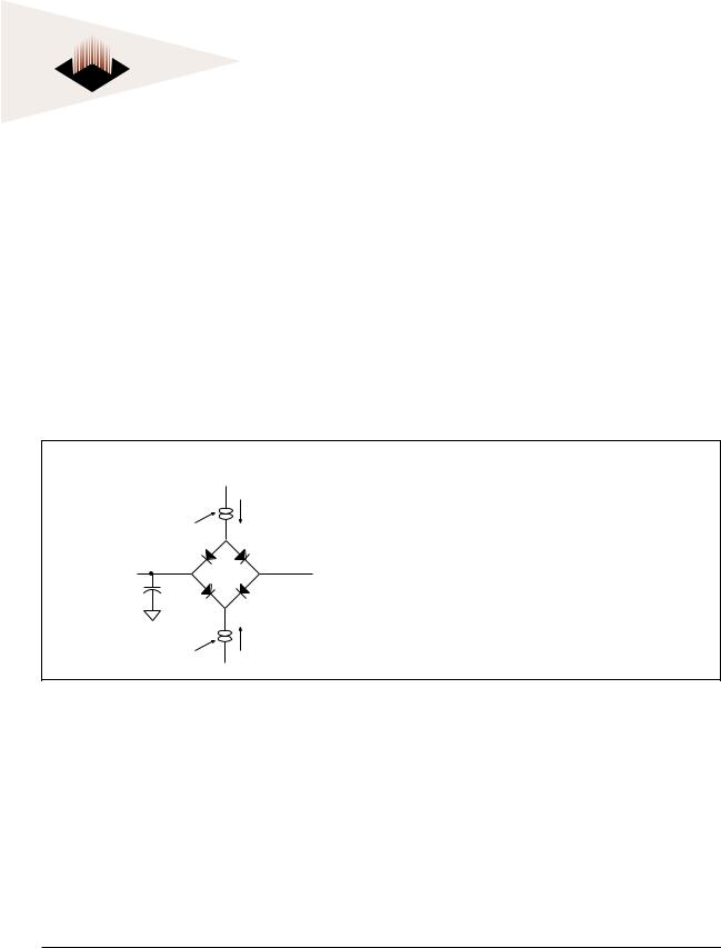
FIG. 2 AC TEST CIRCUIT
|
IOL |
|
Current Source |
D.U.T. |
VZ ≈ 1.5V |
Ceff = 50 pf |
(Bipolar Supply) |
|
|
|
IOH |
|
Current Source |
AC TEST CONDITIONS
Parameter |
Typ |
Unit |
|
|
|
Input Pulse Levels |
VIL = 0, VIH = 3.0 |
V |
|
|
|
Input Rise and Fall |
5 |
ns |
|
|
|
Input and Output Reference Level |
1.5 |
V |
|
|
|
Output Timing Reference Level |
1.5 |
V |
|
|
|
Notes:
VZ is programmable from -2V to +7V. IOL & IOH programmable from 0 to 16mA. Tester Impedance Z0 = 75 W.
VZ is typically the midpoint of VOH and VOL.
IOL & IOH are adjusted to simulate a typical resistive load circuit. ATE tester includes jig capacitance.
3White Electronic Designs Corporation • (602) 437-1520 • www.whiteedc.com

White Electronic Designs |
WSF128K32-XH2X |
FIG. 3 SRAM TIMING WAVEFORM - READ CYCLE |
|
|
|||
|
|
|
|
|
tRC |
|
|
|
ADDRESS |
|
|
|
|
|
|
tAA |
|
|
|
|
SCS |
|
|
|
|
tRC |
|
tACS |
tCHZ |
|
|
|
|
||
ADDRESS |
|
|
|
|
|
|
|
tAA |
|
tCLZ |
|
|
|
|
|
|
|
|
|
|
SOE |
|
|
|
tOH |
|
|
tOE |
tOHZ |
|
|
|
tOLZ |
||
|
|
|
|
||
|
|
|
|
|
|
DATA I/O |
PREVIOUS DATA VALID |
DATA VALID |
DATA I/O |
|
DATA VALID |
|
|
|
|
HIGH IMPEDANCE |
|
|
READ CYCLE 1, (SCS = OE = VIL, SWE = FCS = VIH) |
|
READ CYCLE 2, (SWE = FCS = VIH) |
||
FIG. 4 SRAM WRITE CYCLE - SWE CONTROLLED
|
tWC |
|
ADDRESS |
|
|
tAW |
|
tAH |
|
tCW |
|
|
|
|
SCS |
|
|
tAS |
tWP |
|
|
|
|
SWE |
|
tOW |
|
|
|
tWHZ |
tDW |
tDH |
DATA I/O |
DATA VALID |
|
WRITE CYCLE 1, SWE CONTROLLED (FCS = VIH)
FIG. 5 SRAM WRITE CYCLE - SCS CONTROLLED
|
tWC |
|
|
ADDRESS |
|
|
|
tAS |
tAW |
tAH |
|
tCW |
|||
|
|
||
SCS |
|
|
|
|
tWP |
|
|
SWE |
|
|
|
|
tDW |
tDH |
|
DATA I/O |
DATA VALID |
|
WRITE CYCLE 2, SCS CONTROLLED (FCS = VIH)
White Electronic Designs Corporation • Phoenix AZ • (602) 437-1520 |
4 |
 Loading...